WO2023135696A1 - 機器管理システムおよび冷媒量推定方法 - Google Patents
機器管理システムおよび冷媒量推定方法 Download PDFInfo
- Publication number
- WO2023135696A1 WO2023135696A1 PCT/JP2022/000849 JP2022000849W WO2023135696A1 WO 2023135696 A1 WO2023135696 A1 WO 2023135696A1 JP 2022000849 W JP2022000849 W JP 2022000849W WO 2023135696 A1 WO2023135696 A1 WO 2023135696A1
- Authority
- WO
- WIPO (PCT)
- Prior art keywords
- refrigerant
- amount
- information
- management system
- unit
- Prior art date
- Legal status (The legal status is an assumption and is not a legal conclusion. Google has not performed a legal analysis and makes no representation as to the accuracy of the status listed.)
- Ceased
Links
Images


Classifications
-
- F—MECHANICAL ENGINEERING; LIGHTING; HEATING; WEAPONS; BLASTING
- F24—HEATING; RANGES; VENTILATING
- F24F—AIR-CONDITIONING; AIR-HUMIDIFICATION; VENTILATION; USE OF AIR CURRENTS FOR SCREENING
- F24F11/00—Control or safety arrangements
- F24F11/62—Control or safety arrangements characterised by the type of control or by internal processing, e.g. using fuzzy logic, adaptive control or estimation of values
- F24F11/63—Electronic processing
-
- F—MECHANICAL ENGINEERING; LIGHTING; HEATING; WEAPONS; BLASTING
- F24—HEATING; RANGES; VENTILATING
- F24F—AIR-CONDITIONING; AIR-HUMIDIFICATION; VENTILATION; USE OF AIR CURRENTS FOR SCREENING
- F24F11/00—Control or safety arrangements
- F24F11/30—Control or safety arrangements for purposes related to the operation of the system, e.g. for safety or monitoring
- F24F11/32—Responding to malfunctions or emergencies
- F24F11/36—Responding to malfunctions or emergencies to leakage of heat-exchange fluid
-
- F—MECHANICAL ENGINEERING; LIGHTING; HEATING; WEAPONS; BLASTING
- F24—HEATING; RANGES; VENTILATING
- F24F—AIR-CONDITIONING; AIR-HUMIDIFICATION; VENTILATION; USE OF AIR CURRENTS FOR SCREENING
- F24F11/00—Control or safety arrangements
- F24F11/30—Control or safety arrangements for purposes related to the operation of the system, e.g. for safety or monitoring
- F24F11/32—Responding to malfunctions or emergencies
- F24F11/38—Failure diagnosis
-
- F—MECHANICAL ENGINEERING; LIGHTING; HEATING; WEAPONS; BLASTING
- F24—HEATING; RANGES; VENTILATING
- F24F—AIR-CONDITIONING; AIR-HUMIDIFICATION; VENTILATION; USE OF AIR CURRENTS FOR SCREENING
- F24F11/00—Control or safety arrangements
- F24F11/30—Control or safety arrangements for purposes related to the operation of the system, e.g. for safety or monitoring
- F24F11/48—Control or safety arrangements for purposes related to the operation of the system, e.g. for safety or monitoring prior to normal operation, e.g. pre-heating or pre-cooling
-
- F—MECHANICAL ENGINEERING; LIGHTING; HEATING; WEAPONS; BLASTING
- F24—HEATING; RANGES; VENTILATING
- F24F—AIR-CONDITIONING; AIR-HUMIDIFICATION; VENTILATION; USE OF AIR CURRENTS FOR SCREENING
- F24F11/00—Control or safety arrangements
- F24F11/50—Control or safety arrangements characterised by user interfaces or communication
- F24F11/52—Indication arrangements, e.g. displays
-
- F—MECHANICAL ENGINEERING; LIGHTING; HEATING; WEAPONS; BLASTING
- F25—REFRIGERATION OR COOLING; COMBINED HEATING AND REFRIGERATION SYSTEMS; HEAT PUMP SYSTEMS; MANUFACTURE OR STORAGE OF ICE; LIQUEFACTION SOLIDIFICATION OF GASES
- F25B—REFRIGERATION MACHINES, PLANTS OR SYSTEMS; COMBINED HEATING AND REFRIGERATION SYSTEMS; HEAT PUMP SYSTEMS
- F25B49/00—Arrangement or mounting of control or safety devices
- F25B49/02—Arrangement or mounting of control or safety devices for compression type machines, plants or systems
-
- F—MECHANICAL ENGINEERING; LIGHTING; HEATING; WEAPONS; BLASTING
- F24—HEATING; RANGES; VENTILATING
- F24F—AIR-CONDITIONING; AIR-HUMIDIFICATION; VENTILATION; USE OF AIR CURRENTS FOR SCREENING
- F24F2140/00—Control inputs relating to system states
- F24F2140/20—Heat-exchange fluid temperature
Definitions
- the present disclosure relates to an equipment management system and a refrigerant amount estimation method.
- an air conditioner that estimates the amount of refrigerant in the device by adjusting the temperature so that the temperature of the target space satisfies a predetermined judgment temperature condition and measuring the refrigerant temperature under stable conditions (for example, , see Patent Document 1).
- Patent Document 1 With the conventional technology disclosed in Patent Document 1, it is possible to estimate the amount of refrigerant when the air conditioning load of the outdoor unit and the indoor unit is constant, the compressor frequency is constant, and the refrigeration cycle is stable.
- the air conditioning load on the indoor unit changes depending on factors such as the outside temperature being constant throughout the day, the number of people in the room, and the activity level of the people in the room, an environment where the air conditioning load is constant is realistic. not in Therefore, in the prior art, it is difficult to estimate the amount of refrigerant in an actual use environment, and a special operation is required to estimate the amount of refrigerant.
- the present disclosure has been made in view of the above circumstances, and aims to provide a device management system and a refrigerant quantity estimation method that accurately estimate the refrigerant quantity in the device in an actual usage environment without requiring special operation. one of the purposes.
- a device management system includes a device having a refrigerant, an acquisition unit that acquires measurement information indicating the measurement results of the temperature of the refrigerant in the device, the electrical characteristics of the device, and the environmental information around the device. and an estimating unit for estimating the amount of refrigerant in the device based on the measurement information acquired by the acquiring unit, preset device information regarding the device, and device installation information regarding the installation environment of the device. Prepare.
- an obtaining unit obtains a refrigerant temperature in the device, an electrical characteristic of the device, and an environment around the device. a step of acquiring measurement information indicating a measurement result of information, and an estimation unit based on the measurement information acquired by the acquisition unit, preset device information related to the device, and device installation information related to the installation environment of the device. and estimating the amount of refrigerant in the equipment.
- FIG. 1 is a schematic configuration diagram showing an example of a device management system according to a first embodiment
- FIG. It is a figure which shows an example of the refrigerant circuit of the apparatus which concerns on 1st Embodiment.
- FIG. 3 is an explanatory diagram of measurement locations of temperature measurement points shown in FIG. 2 according to the first embodiment; The figure which shows an example of the refrigerant circuit of the multi-type air conditioner which concerns on 1st Embodiment.
- FIG. 4 is a diagram showing an example of a Mollier diagram immediately after activation according to the first embodiment; The figure which shows an example of the Mollier diagram at the time of the stability which concerns on 1st Embodiment. The figure which shows an example of the electric circuit of the apparatus which concerns on 1st Embodiment.
- FIG. 4 is a diagram showing an example of data items of device acquisition data according to the first embodiment
- FIG. FIG. 5 is a diagram showing an example of device acquisition data transmitted by the device according to the first embodiment
- 1 is a schematic block diagram showing an example configuration of a device management apparatus according to a first embodiment
- FIG. 4 is a flowchart showing an example of refrigerant amount estimation processing according to the first embodiment
- FIG. 4 is an explanatory diagram showing an example of a method for calculating an estimated amount of refrigerant according to the first embodiment
- the schematic block diagram which shows an example of the equipment management system which concerns on 2nd Embodiment.
- FIG. 11 is a diagram showing an example of time-series data of each of a plurality of devices held by a device management apparatus according to the third embodiment;
- the schematic block diagram which shows an example of the equipment management system which concerns on 5th Embodiment.
- FIG. 11 is a diagram showing a display example displayed on a general-purpose device according to the fifth embodiment
- FIG. 11 is a diagram showing a display example displayed on a general-purpose device according to the sixth embodiment
- FIG. 1 is a schematic configuration diagram showing an example of a device management system according to this embodiment.
- the device management system SYS shown in this figure includes a device 1 having a refrigerant and a device management device 2 capable of communicating with the device 1 .
- the device 1 is, for example, an air conditioner that includes an outdoor unit 100 and an indoor unit 200 .
- the device management device 2 is a data management destination that stores communication data from the device 1 and estimates the amount of refrigerant in the device 1 .
- the external terminal 3 and the cloud 4 are exemplified as the device management device 2 .
- the external terminal 3 is a terminal device such as a smartphone or a PC (Personal Computer). In addition to communicating with the device 1 , the external terminal 3 may communicate with the cloud 4 and transmit communication data from the device 1 to the cloud 4 .
- the cloud 4 is a group of arithmetic processing units connected via a communication network such as a public line.
- the device management device 2 may be the external terminal 3 or the cloud 4 .
- the device management system SYS communicates with the device 1 based on device acquisition data 10 acquired by the device 1, device information 20 regarding the device 1, and device installation information 30 regarding the installation environment in which the device 1 is installed.
- a connected external terminal 3 or a device management device 2 such as a cloud 4 estimates the amount of refrigerant in the device 1 .
- the device acquisition data 10 includes a measured value of the coolant temperature in the device 1 (hereinafter referred to as “refrigerant temperature 11”) and a measured value of the electrical characteristics in the device 1 (hereinafter referred to as “electrical input 12”). ) and measurement information such as a measured value of environmental information such as temperature or humidity around the device 1 (hereinafter referred to as “environmental information 13”).
- the device 1 transmits device acquisition data 10 to the device management apparatus 2 .
- the device management device 2 acquires the device acquisition data 10 transmitted from the device 1.
- the device management apparatus 2 also has preset device information 20 and device installation information 30 .
- the device information 20 includes inspection data before shipment.
- the device information 20 includes inspection data (stationary data or time-series data) of refrigerant temperature in the device 1 under specific inspection conditions, electrical characteristics in the device 1, or environmental information, inspection conditions, specifications (configuration) of the device 1 at the time of inspection.
- the device installation information 30 includes the environment or installation state of the place where the device is installed. Details of the device acquisition data 10, the device information 20, and the device installation information 30 will be described later.
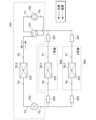
- FIG. 2 is a diagram showing an example of a refrigerant circuit of equipment according to the present embodiment.
- the outdoor unit 100 and the indoor unit 200 are connected by inside/outside connection pipes 301 and 302 .
- a refrigerant in a gaseous state passes through the internal/external connection pipe 301 .
- a coolant in a liquid state passes through the internal/external connection pipe 302 .
- the four-way valve 101 provided in the outdoor unit 100 to switch the circulation direction of the refrigerant, the heating operation and the cooling operation are switched.
- the direction of the solid line arrow indicates the direction of refrigerant flow during cooling operation, and the direction of the broken line arrow indicates the direction of refrigerant flow during heating operation.
- gaseous refrigerant compressed by the compressor 102 of the outdoor unit 100 flows through the four-way valve 101 and the internal/external connection pipe 301 to the indoor heat exchanger 201 of the indoor unit 200 .
- the refrigerant in the indoor heat exchanger 201 exchanges heat with the ambient air to warm the ambient air.
- the refrigerant that has become liquid due to heat exchange flows through the internal/external connection pipe 302 to the expansion valve 103 of the outdoor unit 100 , and flows through the expansion valve 103 into the outdoor heat exchanger 104 .
- the refrigerant in the outdoor heat exchanger 104 exchanges heat with the surrounding air.
- Refrigerant in a gaseous state through heat exchange passes through the four-way valve 101 and returns to the compressor 102 .
- gaseous refrigerant compressed by the compressor 102 of the outdoor unit 100 flows through the four-way valve 101 into the outdoor heat exchanger 104 .
- the refrigerant in the outdoor heat exchanger 104 exchanges heat with the surrounding air.
- the refrigerant that has become liquid due to heat exchange flows through the expansion valve 103 and the internal/external connecting pipe 302 into the indoor heat exchanger 201 of the indoor unit 200 .
- the refrigerant in the indoor heat exchanger 201 exchanges heat with the surrounding air to cool the surrounding air.
- the refrigerant that has become gaseous due to heat exchange returns to the compressor 102 of the outdoor unit 100 through the internal/external connection pipe 301 and the four-way valve 101 .
- FIG. 3 is an explanatory diagram of the temperature measurement points T1 to T8 shown in FIG.
- a temperature sensor is provided on each of the outlet side and the inlet side of the compressor 102, the outlet side measuring point T1 is the outlet side measuring point, and the inlet side measuring point T8 is the suction temperature measuring point.
- the expansion valve 103 and the outdoor heat exchanger 104 of the outdoor unit 100 and the indoor heat exchanger 201 of the indoor unit 200 are each provided with three points: the outlet side, the inlet side, and the middle point between the outlet and the inlet. is provided with a temperature sensor.
- the outdoor heat exchanger 104 functions as a condenser during cooling operation.
- Measurement points T2, T2-3, and T3 are measurement points for the inlet temperature, intermediate temperature, and outlet temperature of the condenser during cooling operation, respectively.
- the outdoor heat exchanger 104 functions as an evaporator during heating operation.
- Measurement points T2, T2-3, and T3 are measurement points for the outlet temperature, intermediate temperature, and inlet temperature of the evaporator during heating operation, respectively.
- the indoor heat exchanger 201 functions as an evaporator during cooling operation.
- Measurement points T6, T6-7, and T7 are measurement points for the inlet temperature, intermediate temperature, and outlet temperature of the evaporator during cooling operation, respectively.
- indoor heat exchanger 201 functions as a condenser during heating operation.
- Measurement points T6, T6-7, and T7 are measurement points for the outlet temperature, intermediate temperature, and inlet temperature of the condenser during heating operation, respectively.
- the measurement point T4 serves as a measurement point for the inlet temperature of the expansion valve 103 during cooling operation, and for the outlet temperature of the expansion valve 103 during heating operation.
- the measurement point T5 serves as a measurement point for the outlet temperature of the expansion valve 103 during cooling operation and for the inlet temperature of the expansion valve 103 during heating operation.
- the device 1 may be a multi-type air conditioner (a so-called package air conditioner) in which a plurality of indoor units 200 are connected to one outdoor unit 100.
- a multi-type air conditioner a so-called package air conditioner
- FIG. 4 is a diagram showing an example of a refrigerant circuit of a multi-type air conditioner.
- FIG. 4 shows an example of a refrigerant circuit when two indoor units 200 are connected to the outdoor unit 100.
- the same reference numerals are assigned to the components corresponding to those in FIG.
- the configuration of the illustrated refrigerant circuit is the same as the example of the refrigerant circuit illustrated in FIG. 2 except that the number of indoor units 200 is different. Note that the number of indoor units 200 is not limited to two.
- the indoor units 200 are set to No. 1, No. 2, and so on. Then, assign the unit number such as "discharge temperature of unit 1, inlet temperature of condenser, ", "discharge temperature of unit 2, inlet temperature of condenser, ", and the refrigerant temperature for each unit are treated separately.
- the number of devices 1 is basically one for one outdoor unit 100 regardless of whether there is one indoor unit 200 or a plurality of indoor units 200 .
- FIG. 5 is a diagram showing an example of a Mollier diagram immediately after startup (in the initial stage of operation).
- FIG. 6 is a diagram showing an example of a Mollier diagram at the time of stability.
- all measurement points T1 to T8 are within the gas-liquid two-phase region (two-phase region) (see FIG. 5).
- the pressure difference between the condenser and the evaporator increases, and at the discharge temperature measurement point T1, it is gasified and transitions into the gas phase region (see FIG. 6). ).
- the enthalpy decreases due to heat exchange with the air by the condenser. If the amount of refrigerant gas and the amount of heat exchange in the condenser are sufficient, the measurement point T3 transitions into the liquid phase region (see FIG. 6). On the other hand, if the amount of refrigerant gas is insufficient, heat exchange in the condenser and evaporator will be insufficient.
- FIG. 7 is a diagram showing an example of an electric circuit of the device 1 according to this embodiment.
- the same reference numerals are given to the components corresponding to the parts in FIG.
- the outdoor unit 100 includes an outdoor unit control section 110.
- the outdoor unit control unit 110 includes a microcomputer, controls each unit of the outdoor unit 100 and obtains measurement values of various sensors provided in the outdoor unit 100 .
- the outdoor unit control unit 110 acquires the measured values of the temperature sensors provided at the refrigerant temperature measurement points T1, T2, T2-3, T3, T4, T5, and T8 described in FIGS. do.
- the outdoor unit control unit 110 controls switching of the refrigerant flow direction in the four-way valve 101, controls the compressor 102, controls the opening degree of the expansion valve 103, and controls the outdoor fan 105 that blows air to the outdoor heat exchanger 104. Rotation control, etc.
- the compressor 102 includes a compression section 102a and a compressor motor 102b.
- Compression part 102a has a compression mechanism such as a rotary type or a scroll type, compresses the refrigerant sucked from the inlet side, and discharges it from the outlet side.
- Compressor motor 102b includes a three-phase motor whose rotation can be controlled by inverter 120, and drives the compression mechanism of compression section 102a. By controlling the inverter 120, the outdoor unit control section 110 controls the rotation of the compressor motor 102b to control the compression mechanism of the compression section 102a.
- the indoor unit 200 includes an indoor unit control section 210.
- the indoor unit control unit 210 includes a microcomputer, controls each unit of the indoor unit 200, and acquires measurement values of various sensors provided in the indoor unit 200. For example, the indoor unit control unit 210 acquires the measured values of the temperature sensors provided at the refrigerant temperature measurement points T6, T6-7, and T7 described with reference to FIGS. 2 and 3, respectively.
- the indoor unit control unit 210 also controls the rotation of the indoor fan 202 that blows air to the indoor heat exchanger 201, and the like.
- the indoor unit 200 includes a wireless device 220.
- the wireless device 220 is, for example, one of device-associated devices added to the indoor unit 200 as an option.
- the wireless device 220 connects to a communication network such as a wireless LAN (Local Area Network) or the Internet by wireless communication, and performs data communication with the device management device 2 (the external terminal 3 or the cloud 4).
- a communication network such as a wireless LAN (Local Area Network) or the Internet by wireless communication, and performs data communication with the device management device 2 (the external terminal 3 or the cloud 4).
- the indoor unit control section 210 is connected to the outdoor unit control section 110 via an internal/external communication line 310 .
- the indoor unit controller 210 generates device acquisition data 10 based on data acquired from the outdoor unit controller 110 via the indoor/outdoor communication line 310 and data acquired by the indoor unit controller 210 itself. Then, the indoor unit control section 210 transmits the device acquisition data 10 to the device management device 2 (the external terminal 3 or the cloud 4) via the wireless device 220.
- the air conditioning load of the outdoor and indoor units is constant like in a test room.
- the air conditioning load applied to the outdoor unit changes due to the outside temperature not being constant throughout the day.
- the air conditioning load applied to the indoor unit changes depending on the number of people in the room or their activity status.
- the device management device 2 (external The terminal 3 or the cloud 4) estimates the amount of refrigerant in the device 1.
- the equipment management system SYS can accurately estimate the amount of refrigerant in the equipment 1 in the actual use environment without requiring any special operation. A detailed description will be given below.
- FIG. 8 is a diagram showing an example of data items of the device acquisition data 10 according to this embodiment.
- the device acquisition data 10 includes coolant temperature 11, electrical input 12, and environment information 13.
- FIG. 8 is a diagram showing an example of data items of the device acquisition data 10 according to this embodiment.
- the device acquisition data 10 includes coolant temperature 11, electrical input 12, and environment information 13.
- FIG. 8 is a diagram showing an example of data items of the device acquisition data 10 according to this embodiment.
- the device acquisition data 10 includes coolant temperature 11, electrical input 12, and environment information 13.
- the refrigerant temperature 11 includes, for example, the discharge temperature, the temperature at any point from the inlet to the outlet of the condenser and evaporator (eg, inlet temperature, intermediate temperature, outlet temperature), the temperature of the expansion valve 103 (eg, inlet temperature , outlet temperature), inlet temperature, etc.
- the coolant temperature 11 may include the temperatures of all the locations described above, or may include some of them.
- the refrigerant temperature 11 includes part of the above, it preferably includes at least the discharge temperature.
- the refrigerant temperature 11 does not include all of the inlet temperature, intermediate temperature, and outlet temperature of the condenser and evaporator, it preferably includes at least the intermediate temperature.
- Temperature sensors may also be provided in the internal/external connection pipes 301 and 302, and the temperature of the internal/external connection pipe 301 (for example, inlet temperature and outlet temperature) may be included in the coolant temperature 11.
- the coolant temperature 11 is not limited to the temperature at the location described above, and may include the coolant temperature at any location that can be acquired by the device 1 .
- the refrigerant temperature 11 includes measured values of the refrigerant temperature at more points, the higher the refrigerant amount estimation accuracy.
- the electrical input 12 includes, for example, voltages (bus voltage, line voltage, phase voltage), currents (bus current, line current, phase current), rotation speeds (current rotation speed, command speed), power consumption, etc. Also, the electrical input 12 includes, for example, voltage (bus voltage, line voltage, phase voltage), current (bus current, line current, phase current), frequency (current frequency, command frequency), consumption of the compressor 102, Electricity, etc. are included. Further, the electrical input 12 includes, for example, the degree of opening of the expansion valve 103 (current degree of opening, commanded degree of opening), power consumption, and the like. The electrical input 12 also includes, for example, the voltage (primary voltage) and current (primary current) on the power supply side, and the power consumption of device-attached devices (eg, wireless device 220, heaters, air cleaning devices, etc.).
- device-attached devices eg, wireless device 220, heaters, air cleaning devices, etc.
- the power consumption of the device-attached device is determined by the voltage, current, or power that cannot be obtained by the device 1. It is used to estimate by the indirect method from the total sum of
- the electrical input 12 may include all of the above data items, or may include some of them.
- the electrical input 12 may include at least the number of revolutions (current number of revolutions) of the outdoor fan 105 and the indoor fan 202, the bus current and current frequency of the compressor 102, and the current opening of the expansion valve 103. preferable.
- the electrical input 12 may include arbitrary electrical characteristics within the device 1 that can be acquired by the device 1 . The more data items included in the electrical input 12, the more accurate the refrigerant quantity estimate.
- the environmental information 13 includes, for example, ambient temperature (outdoor temperature, indoor temperature) and humidity (outdoor humidity, indoor humidity) acquired by the outdoor unit 100 and the indoor unit 200 .
- the environment information 13 may include all of the above data items, or may include some of them.
- the environment information 13 preferably includes at least room temperature.
- the environment information 13 may include environment information that the device 1 can acquire. The more data items are included in the environmental information 13, the higher the refrigerant amount estimation accuracy.
- the device 1 transmits the device acquisition data 10 described with reference to FIG.
- FIG. 9 is a diagram showing an example of device acquisition data 10 transmitted by the device 1. As shown in FIG. For example, as shown in FIG. 9, the device 1 transmits time-series data of device acquired data 10 measured at regular time intervals. Note that the device 1 may transmit fixed point data under certain conditions when transmitting the device acquired data 10 .
- FIG. 10 is a diagram showing an example of data items of the device information 20 according to this embodiment.
- the device information 20 includes pre-shipment inspection data, inspection conditions, and specifications (configuration) of the device 1 at the time of inspection.
- the common items include the specifications (configuration) of the device 1 at the time of inspection.
- common items include date and time of inspection (No. 1), test room used for inspection (No. 2), manufacturing information and product specifications of the inspected device 1, and the like.
- the manufacturing information includes lot number (No. 3), manufacturing year (No. 6), and the like.
- the model No. 4
- capacity No.
- the product specifications include power supply specifications, refrigerant type and amount, type and amount of refrigerating machine oil, type of compressor 102, stroke volume, The specifications of the compressor motor 102b, the internal volume of the compressor 102, the internal volume of the outdoor heat exchanger 104, the internal volume of the indoor heat exchanger 201, the internal volume of the receiver (No. 7 to No. 18), etc. are included.
- the receiver is provided, for example, in the vicinity of the connecting portion between the expansion valve 103 of the outdoor unit 100 and the internal/external connection pipe 302 .
- This receiver is provided to store surplus refrigerant because the required amount of refrigerant differs between cooling operation and heating operation.
- the internal volume of the outdoor unit 100 is larger than that of the indoor unit 200, and the amount of refrigerant in the indoor unit 200 serving as a condenser during heating operation is smaller than that of the outdoor unit 100 during cooling operation.
- the pre-shipment inspection data includes the refrigerant temperature in the device 1 under specific inspection conditions, electrical characteristics in the device 1, or inspection data of environmental information (steady data or time-series data).
- No. of inspection data items 1 to No. Item 5 is a common inspection condition regardless of the type of equipment 1 .
- the common inspection conditions include test conditions (for example, cooling standard or heating standard), outdoor DB (Dry Bulb), outdoor WB (Wet Bulb), indoor DB, and indoor WB.
- the No. 8 to No. Item 11 is an inspection condition that differs for each device or for each performance band of the device, and includes the command frequency of the compressor 102, the command rotation speed of the indoor fan 202 and the outdoor fan 105, and the command opening of the expansion valve 103. such as instrument control settings for each individual examination.
- the No. 6 to No. 7 and no. 12 to No. Item 19 is inspection data (stationary data or time-series data) under the above inspection conditions.
- the inspection data includes the capacity of the indoor unit 200 (indoor capacity), power consumption, thermal characteristics of the outdoor heat exchanger 104 and the indoor heat exchanger 201, discharge temperature, inlet temperature and outlet temperature of the condenser and evaporator, Inhalation temperature etc. are included.
- the device information 20 may include all of the above data items, or may include some of them.
- the device information 20 preferably includes at least the refrigerant type and the volume of space through which the refrigerant can flow.
- the volume of the space through which the refrigerant can flow is the internal volume of the compressor 102, the internal volume of the outdoor heat exchanger 104, the internal volume of the indoor heat exchanger 201, the internal volume of the receiver, and the like.
- the volume of the space through which the refrigerant can flow may include part of the internal volume of the compressor 102, the internal volume of the outdoor heat exchanger 104, the internal volume of the indoor heat exchanger 201, and the internal volume of the receiver. and all may be included.
- the device information 20 may include any measurable information at the time of inspection. The more data items included in the device information 20, the higher the refrigerant amount estimation accuracy.
- sampling inspections are generally conducted at the time of product shipment. In sampling inspections, for example, the most recent lot is used as a representative value.
- FIG. 11 is a diagram showing an example of data items of the device installation information 30 according to this embodiment.
- the device installation information 30 includes information such as the installation location or installation environment of the device 1 .
- the device installation information 30 includes the position (latitude, longitude) of the installation location of the device 1, the building specifications, the installation direction (facing north, facing south, etc.), the installation method of the outdoor unit 100 (on the roof, on the ground, on the ceiling, etc.). hanging, wall surface, etc.), the height of the indoor unit 200 (height from the floor surface), the size of the indoor space, the length and diameter of the internal and external connection pipes 301 and 302 that connect the outdoor unit 100 and the indoor unit 200,
- the height difference (indoor/outdoor height difference) between the outdoor unit 100 and the indoor unit 200 is included as information such as the installation location or the installation environment.
- the indoor/outdoor height difference is the height difference between the position where the inside/outside connection pipes 301 and 302 are connected to the outdoor unit 100 and the position where the inside/outside connection pipes 301 and 302 are connected to the indoor unit 200 .
- the device installation information 30 may include all of the above data items, or may include some of them.
- the equipment installation information 30 preferably includes the length and diameter of the internal/external connection pipes 301 and 302, which are related to the volume of the space through which the refrigerant can flow.
- the device installation information 30 may include any information other than the above data items regarding the environment or installation state of the installation location. The more data items included in the equipment installation information 30, the higher the refrigerant amount estimation accuracy.
- the installation location or installation environment of the device 1 differs depending on the user. If the installation location or installation environment is different, the estimation of the refrigerant amount is also affected. For example, regarding the installation location of the device 1, when the outdoor unit 100 is installed on the first floor, when the indoor unit 200 is installed on the first floor and when the indoor unit 200 is installed on the third floor, the outdoor unit The height of the indoor unit 200 with respect to 100 is generally different by about 5 m. Therefore, even if the amount of refrigerant in the device 1 excluding the internal/external connection pipes 301 and 302 is the same, the lengths of the internal/external connection pipes 301 and 302 are different, so it is assumed that different behaviors will be exhibited in terms of the refrigeration cycle. . Therefore, it is conceivable that the installation location of the device 1 affects the estimation of the amount of refrigerant.
- the lengths of the internal/external connection pipes 301 and 302 may differ. In that case, since the refrigerant is distributed in the internal/external connection pipes 301 and 302, if the additional refrigerant is not charged for the length of the internal/external connection pipes 301 and 302, the amount of refrigerant in the device 1 excluding the internal/external connection pipes will be reduced. It is conceivable that it will decrease in general and cause a gas shortage. Regarding the installation environment of the device 1, the lengths of the internal/external connection pipes 301 and 302 differ depending on whether the outdoor unit 100 is suspended from the ceiling, placed on the ground, or placed on the roof.
- the air conditioning load differs depending on whether it is facing south and exposed to direct sunlight or facing north and is in the shade, which affects the refrigeration cycle. Therefore, it is conceivable that the installation environment of the device 1 similarly affects the estimation of the amount of refrigerant.
- the insulation performance differs depending on whether the building in which the device 1 is installed is made of wood or reinforced concrete. For example, if the building is made of wood and has low heat insulation, the air conditioning load will increase, which may affect the refrigeration cycle and affect the estimation of the amount of refrigerant.
- the device management apparatus 2 uses the device installation information 30 to estimate the amount of refrigerant according to the installation location or installation environment of the device 1 without fixing the installation location or installation environment of the device 1. be able to.
- FIG. 12 is a schematic block diagram showing an example of the configuration of the device management apparatus 2 according to this embodiment.
- the device management device 2 is the external terminal 3 or the cloud 4 as described above, and includes, for example, a storage unit 401 , a communication unit 402 and a processing unit 403 .
- the storage unit 401 stores control programs for controlling each unit of the device management apparatus 2 and various data.
- the storage unit 401 includes DRAM (Dynamic Random Access Memory), EEPROM (Electrically Erasable Programmable Read Only Memory), Flash ROM, HDD (Hard Disk Drive), SSD (Solid State Drive) ), etc.
- the device information 20 (see FIG. 10) and the device installation information 30 (see FIG. 11) are pre-stored in the storage unit 401 .
- the communication unit 402 performs data communication with the device 1 or other devices by wireless communication.
- the communication unit 402 connects to a communication network such as a wireless LAN (Local Area Network) or the Internet by wireless communication, and performs data communication with the device 1 or other devices. do.
- the communication unit 402 may also support wired communication.
- the processing unit 403 has a CPU (Central Processing Unit) executing a control program stored in the storage unit 401 to perform a refrigerant amount estimation process for estimating the amount of refrigerant. 405 and an output unit 406 .
- the acquisition unit 404 acquires the device acquisition data 10 (see FIG. 8) from the device 1 (for example, the indoor unit 200) via the communication unit 402 and stores it in the storage unit 401.
- FIG. Estimating unit 405 estimates the amount of refrigerant in device 1 .
- the estimated refrigerant amount is referred to as "estimated refrigerant amount 40".
- the estimation unit 405 calculates the estimated refrigerant amount 40 in the device 1 based on the device acquisition data 10 acquired by the acquisition unit 404 and the device information 20 and the device installation information 30 stored in the storage unit 401. calculate.
- the output unit 406 outputs the estimation result of the refrigerant amount by the estimation unit 405 .
- FIG. 13 is a flowchart showing an example of refrigerant amount estimation processing according to the present embodiment.
- the device 1 (for example, the indoor unit 200) sends the device acquired data 10 to the device management device 2, either voluntarily or passively by the user who operates the device 1, periodically (for example, every five minutes). Send.
- the device management apparatus 2 receives the device acquisition data 10 transmitted from the device 1 (step S101).
- the device management apparatus 2 Upon receiving the device acquisition data 10 transmitted from the device 1, the device management apparatus 2 acquires the device acquisition data 10 each time it is received, and stores and accumulates it in the storage unit 401 (step S103).
- the device management device 2 estimates the amount of refrigerant in the device 1 at any timing, in addition to internal periodic processing.
- the device management apparatus 2 determines whether or not it is time to estimate the amount of refrigerant (step S105). If it is not the refrigerant amount estimation timing (NO), the process returns to step S101, and the device management apparatus 2 periodically receives the device acquisition data 10 from the device 1 (step S103).
- the device management device 2 estimates the amount of refrigerant in the device 1 (step S107). Specifically, the equipment management apparatus 2 calculates the estimated refrigerant amount 40 based on the accumulated equipment acquisition data 10 and the equipment information 20 and the equipment installation information 30 held internally in advance. Then, the device management device 2 outputs the estimated refrigerant amount (estimated refrigerant amount 40) (step S109).
- FIG. 14 is an explanatory diagram showing an example of a method for calculating an estimated amount of refrigerant according to this embodiment.
- the equipment management apparatus 2 calculates an estimated refrigerant amount 40 by summing a converted refrigerant amount 41, a dissolved refrigerant amount 42, and a retained refrigerant amount 43, for example.
- the estimated refrigerant amount 40 may be set directly if it can be determined from the refrigerant charging operation or the like.
- the equivalent refrigerant amount 41 is the amount of refrigerant in the main refrigerant state in each part that constitutes the device 1 .
- the converted refrigerant amount 41 indicates the amount of refrigerant in the gas phase portion.
- the converted refrigerant amount 41 indicates the amount of refrigerant in the gas phase portion.
- the converted refrigerant amount 41 indicates the refrigerant amount using the two-phase average density.
- the equivalent refrigerant amount 41 is calculated by multiplying the internal volume of each part of the device 1 by the refrigerant density.
- a converted refrigerant amount 41 is included in the internal volume 31 of the internal/external connection pipes 301 and 302 determined from the equipment installation information 30 (the length and diameter of the internal/external connection pipes 301 and 302) and the equipment information 20. It is calculated by multiplying the internal volume 51 of each part in the equipment 1 and the refrigerant density 50 in each part.
- the refrigerant density in each component can be obtained from the relationship between pressure and density by converting the refrigerant temperature of the equipment acquisition data 10 into pressure.
- the relationship between pressure and density is determined by the type of refrigerant.
- the data of the refrigerant pressure can be directly acquired from the device 1, it can be obtained based on the acquired refrigerant pressure or pressure data.
- Each component described here is a component having a space in which a refrigerant can flow among the components constituting the device 1, and includes, for example, the compressor 102, the outdoor heat exchanger 104, the indoor heat exchanger 201, the receiver, the internal and external They are connecting pipes 301 and 302 and the like.
- the dissolved refrigerant amount 42 is the amount of refrigerant dissolved in the refrigerating machine oil used in the equipment 1 .
- the dissolved refrigerant amount 42 is calculated by summing up the product of the retained oil amount 52 of each part and the oil dissolution ratio 53 of each part for each part.
- the total amount of oil in the equipment 1 is the value of the oil amount in the equipment information 20 shown in FIG.
- a retained oil amount 52 remaining in each component out of the amount of oil in the equipment 1 is determined based on the equipment acquisition data 10, the equipment information 20, and the equipment installation information 30 according to the operating conditions (cooling, heating, etc.). obtained by experiments or numerical calculations.
- the device information 20 further includes a retained oil amount 52 for each component determined by this experiment or numerical calculation.
- the oil dissolution ratio 53 of each component can be calculated using a Daniel chart showing the amount of refrigerant dissolved in refrigerating machine oil according to temperature and pressure by an experimental method.
- the current oil dissolution ratio 53 of each part can be calculated using the measured value of the refrigerant temperature of each part included in the device acquisition data 10 and the Daniel chart. When obtaining using a Daniel chart, it may be calculated by an approximation formula.
- the retained oil amount 52 of each part may target only the parts that have a large internal volume and in which the refrigerating machine oil tends to stagnate, and may exclude the parts in which the refrigerating machine oil is less likely to stagnate.
- refrigerating machine oil tends to stay in the compressor 102, the outdoor heat exchanger 104, and the indoor heat exchanger 201 and is present in large amounts.
- the retained refrigerant amount 43 is the amount of liquid refrigerant retained in each component (receiver, internal/external connection pipes 301, 302, etc.) in the gas-liquid two-phase region. If the cross-sectional area of the coolant channel of each component is small, the flow velocity of the coolant becomes faster, making it difficult for the coolant to stagnate. Therefore, for example, as shown in FIG. 14, the amount of retained refrigerant 43 circulates through the cross-sectional area of the refrigerant flow path of each component and inside the device 1 based on the device acquisition data 10, the device information 20, and the device installation information 30. It can be obtained by experiments or numerical calculations depending on the refrigerant flow rate.
- the flow rate of refrigerant circulating in the device 1 is determined by the frequency of the compressor 102 and the density of the suctioned refrigerant.
- the suctioned refrigerant density can be uniquely obtained from the amount of heat exchange between the condenser and the evaporator in the equipment 1 . Note that it can also be obtained from the intake temperature or pressure acquired by the device 1 .
- the amount of heat exchanged between the condenser and the evaporator is determined by the outdoor or indoor environmental load, and can be obtained from the device acquisition data 10 and the device installation information 30 at this time.
- the device management device 2 controls the refrigerant temperature in the device 1, the electrical input (electrical characteristics) of the device 1, and the environmental information around the device 1. Acquires device acquisition data 10 (measurement information) indicating the measurement result of . Then, the equipment management apparatus 2 calculates an estimated refrigerant amount 40 based on the obtained equipment acquisition data 10 and preset equipment information 20 and equipment installation information 30 to estimate the amount of refrigerant in the equipment 1 . In addition, for example, the estimation of the refrigerant amount may be performed by the external terminal 3 , the cloud 4 , or the cloud 4 via the external terminal 3 .
- the equipment management system SYS can estimate the amount of refrigerant in the equipment 1 during normal operation, unlike the conventional method of estimating the amount of refrigerant. That is, the equipment management system SYS can accurately estimate the amount of refrigerant in the equipment in the actual use environment without requiring any special operation.
- the device information 20 includes at least information about the volume of the space through which the refrigerant can flow within the device 1 and the type of refrigerant possessed by the device 1 .
- the equipment management system SYS can estimate the amount of refrigerant in the space in which the refrigerant can flow in the equipment 1 according to the refrigerant type.
- the device management device 2 calculates the amount of refrigerant in the device 1 based on the volume of the space through which the refrigerant can flow in the device 1 and the refrigerant density determined based on the refrigerant temperature and refrigerant type in the device 1 .
- the device management system SYS can accurately estimate the amount of refrigerant in the device 1 .
- the equipment management device 2 further calculates the amount of refrigerant dissolved in the refrigerating machine oil used in the equipment 1 (dissolved refrigerant amount 42) and the amount of refrigerant in the liquid stagnant portion (accumulated refrigerant amount 43) in the equipment 1.
- the amount of refrigerant is calculated. That is, the equipment management apparatus 2 calculates the estimated refrigerant amount 40 by summing the converted refrigerant amount 41 , the dissolved refrigerant amount 42 , and the retained refrigerant amount 43 .
- the equipment management system SYS can accurately estimate the amount of refrigerant in the equipment 1 even in a transient phenomenon.
- an outdoor unit 100 including a compressor 102, an outdoor heat exchanger 104, and an expansion valve 103, and an indoor unit 200 including an indoor heat exchanger 201 use internal/external connection pipes 301 and 302 through which refrigerant flows.
- the device installation information 30 includes at least information about the volume of the internal/external connection pipes 301 and 302 (for example, the diameter and length of the internal/external connection pipes 301 and 302).
- the device management system SYS can accurately estimate the amount of refrigerant in the device 1, including the connecting portion between the outdoor unit 100 and the indoor unit 200.
- the environmental information around the device 1 includes at least information about the ambient temperature of the device 1 .
- the ambient temperature is the temperature (indoor temperature) of the environment (indoor) in which the indoor unit 200 is installed or the temperature (outdoor temperature) of the environment (outdoor) in which the outdoor unit 100 is installed.
- the device management system SYS can accurately estimate the amount of refrigerant in the device 1 in consideration of the ambient temperature of the device 1 .
- the device management system SYS is equipped with an external terminal 3 or a cloud 4 capable of communicating with the device 1 as the device management device 2 . Accordingly, the device management system SYS can be easily applied to various devices 1 because the device 1 does not need to have a function necessary for estimating the amount of refrigerant.
- the refrigerant amount estimation method for estimating the refrigerant amount in the device 1 having the refrigerant is such that the device management device 2 determines the refrigerant temperature in the device 1, the electrical input of the device 1 ( electrical characteristics), and device acquired data 10 (measurement information) indicating the measurement result of environmental information around the device 1; acquired device acquired data 10; and estimating the amount of refrigerant in the device 1 based on the installation information 30 .
- the equipment management system SYS can estimate the amount of refrigerant in the equipment 1 during normal operation, unlike the conventional method of estimating the amount of refrigerant. That is, the equipment management system SYS can accurately estimate the amount of refrigerant in the equipment in the actual use environment without requiring any special operation.
- FIG. 15 is a schematic configuration diagram showing an example of a device management system according to this embodiment.
- the device management system SYS shown in this figure includes a plurality of devices 1 having refrigerant and a device management device 2 capable of communicating with each device 1 .
- this figure shows an example in which there are three devices 1, the number may be two or four or more.
- the configuration and operation of the refrigerant amount estimation process in the equipment management system SYS are the same as in the first embodiment.
- the acquisition unit 404 acquires the device acquisition data 10 from each of the multiple devices 1 .
- the estimation unit 405 calculates the amount of refrigerant (total amount of refrigerant) in the plurality of devices 1 based on the device acquisition data 10 acquired by the acquisition unit 404 and the preset device information 20 and device installation information 30 .
- the device management system SYS collectively manages the device acquisition data 10, the device information 20, and the device installation information 30 of each of the plurality of devices 1, thereby controlling the total refrigerant amount (refrigerant amount) of the plurality of devices 1. total amount) can be estimated.
- the equipment management system SYS can also individually estimate the amount of refrigerant for each of the plurality of equipment 1 .
- the basic configuration of the equipment management system SYS according to this embodiment is the same as in the first and second embodiments. Also, the basic operation of the equipment management system SYS according to this embodiment is the same as in the first and second embodiments, but differs in that the refrigerant management value is used.
- refrigerants with a high global warming potential tend to gradually reduce their use in the market.
- GWP of R410a is 2090 and GWP of R32 is 675.
- R410a is a refrigerant that has three times as much global warming effect as R32. Therefore, when R410a is used, the impact on the global environment (global warming) is equalized by limiting the amount of refrigerant to one third of the amount of refrigerant when using R32.
- the amount of refrigerant whose use is restricted in the device 1 for each type of refrigerant is the above-mentioned refrigerant management value.
- the refrigerant management value is calculated as the sum of the charged refrigerant amount at the time of shipment of the device 1 and the additional charged refrigerant amount required for the device 1 .
- FIG. 16 is a schematic configuration diagram showing an example of a device management system according to this embodiment.
- the equipment management device 2 estimates the amount of refrigerant in the equipment 1 based on the equipment acquisition data 10, the equipment information 20, and the equipment installation information 30, and calculates the estimated refrigerant amount (estimated refrigerant amount 40) and the refrigerant management value. can be compared to determine whether the amount of refrigerant in the device 1 is excessive or insufficient.
- the configuration is such that the amount of refrigerant in the device 1 is estimated at an arbitrary timing, so time-series data as shown in FIG. 17 can be retained.
- the estimating unit 405 calculates the refrigerant management value of the device 1 based on the sum of the charging refrigerant amount at the time of shipment of the device 1 and the additional charging refrigerant amount required for the device 1 . Then, the estimating unit 405 compares the estimated refrigerant amount value in the device 1 with the refrigerant management value of the device 1, and determines whether the amount of refrigerant in the device is excessive or insufficient.
- FIG. 17 is a diagram showing an example of time-series data held by the device management apparatus. This figure shows time-series data of the refrigerant management value and the estimated refrigerant amount value at each time.
- the estimated refrigerant amount value from time t0 to t1 is an estimated value of the refrigerant amount filled in the device 1 at the time of installation, and corresponds to the charged refrigerant amount of the device 1 at the time of shipment.
- the estimated refrigerant amount value is close to the refrigerant management value at time t2.
- the estimated refrigerant amount after time t3 decreases, and then after time t4, the estimated refrigerant amount reaches a certain value. value stabilizes.
- the device management device 2 can determine whether the amount of refrigerant in the device 1 is excessive or insufficient by comparing the difference between the refrigerant management value and the estimated refrigerant amount value based on the time-series data shown in FIG.
- the equipment management device 2 can grasp that the refrigerant gas is leaking.
- the device management device 2 determines whether the amount of refrigerant in the device 1 is excessive or deficient at an arbitrary timing with high determination accuracy (for example, after 30 minutes have passed since the start of the device 1), or periodically (for example, (every one minute), and output as instantaneous values or time-series data.
- the equipment management device 2 simply determines whether the amount of refrigerant in the equipment 1 is excessive or insufficient when judging whether the amount of refrigerant is excessive or insufficient for one equipment 1 .
- the device management device 2 can also manage the amount of refrigerant used in the market when judging whether the amount of refrigerant is excessive or insufficient for a plurality of devices 1 .
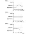
- FIG. 18 is a diagram showing an example of time-series data of each of a plurality of devices 1 (here, device A, device B, and device C) held by the device management apparatus 2. As shown in FIG.
- the device management apparatus 2 obtains the sum of the estimated refrigerant amount values at time t0 when each of the plurality of devices 1 is installed, so that the device management apparatus 2 can grasp the total refrigerant amount of the plurality of devices 1 at the time of installation. can.
- only device A is additionally charged with refrigerant between time t1 and time t2, and the refrigerant gas in device A decreases between time t3 and time t4, so refrigerant leakage occurs.
- device C has refrigerant leakage between time t2 and time t3.
- the devices A to C were removed at time t4, it can be seen that the rest of the refrigerant, excluding the refrigerant leaked from the devices A and C, could be recovered.
- the recovered refrigerant does not affect the environment even if it is replaced with a new device 1 having the same amount of refrigerant.
- the device 1 having the refrigerant can be used continuously.
- the new device 1 uses a different type of refrigerant, it can be replaced without affecting the environment by applying a refrigerant control value according to the type of refrigerant.
- the basic configuration of the equipment management system SYS according to this embodiment is the same as in the first and second embodiments. Further, the basic operation of the device management system SYS according to this embodiment is the same as in the first and second embodiments, but the performance of the device 1 is estimated based on the estimated refrigerant amount 40 and the estimated The difference is that the obtained operating performance is compared with the device information 20 of the device 1, published inspection data, catalog information, or the like.
- the catalog information is information described in the catalog of the manufacturer of the device 1 and includes, for example, numerical values regarding the specifications of the device 1 .
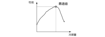
- FIG. 19 is a diagram showing an example of the relationship between the amount of refrigerant and the performance of equipment according to this embodiment.
- FIG. 20 is a diagram showing an example of comparison with catalog values for the relationship between the performance of the device and the air temperature according to this embodiment.
- the performance of the equipment 1 indicates, for example, operation performance such as cooling, heating, dehumidification, and freezing. Note that the power consumption of the device 1 may be used as the performance of the device 1 .
- the equipment management device 2 calculates the estimated refrigerant amount 40 of the equipment 1 having the characteristics as shown in FIG. Then, the device management apparatus 2 summarizes the calculated performance of the device 1 as characteristics as shown in FIG. 19 is determined by numerical calculation based on the device information 20 and the device installation information 30. FIG. Similarly, the example shown in FIG. 20 is also determined by numerical calculation based on the device information 20, published inspection data, or catalog information. The inspection data or catalog information to be published is included in the equipment information 20 .
- the device management system SYS estimates the performance of the device 1 based on the device information 20, the device installation information 30, and the estimated amount of refrigerant, thereby grasping the performance of the device 1. can do. Further, when the device management system SYS has a plurality of devices 1, the device management system SYS can grasp the performance of each device 1 as well as the performance of the plurality of devices 1 as a whole. Furthermore, the device management system SYS compares the estimated performance of each device 1 or the overall performance of a plurality of devices 1 with the device information 20, published inspection data, or catalog information, thereby Performance can be evaluated, and, for example, the adequacy of the performance of the device 1 can be grasped.
- the basic configuration of the equipment management system SYS according to this embodiment is similar to that of the first and second embodiments, but differs in that a general-purpose device is further provided.
- FIG. 21 is a schematic configuration diagram showing an example of a device management system according to this embodiment.
- the equipment management apparatus 2 is configured to be able to communicate with the general-purpose device 5 .
- the general-purpose device 5 is an example of an external device, such as a device having a display screen (eg, smart phone, PC) or a device that emits sound (eg, wireless earphones).
- the basic operation of the equipment management system SYS is the same as in the first to fourth embodiments, but the estimated refrigerant amount 40 of the equipment 1 calculated by the equipment management device 2 or information based on the performance is sent from the general-purpose device 5 The difference is that the output provides visual or auditory guidance or warning to the user.
- the device management device 2 transmits the estimated refrigerant amount 40 or performance information of the device 1 to the general-purpose device 5 to display it.
- the equipment management apparatus 2 transmits information about excess or deficiency of the amount of refrigerant in the equipment 1 determined based on the result of comparison between the value of the estimated refrigerant amount 40 of the equipment 1 and the refrigerant management value to the general-purpose device 5. It may be displayed on the general-purpose device 5 by doing so.
- the equipment management apparatus 2 transmits to the general-purpose device 5 the information of the judgment result based on the comparison between the performance of the equipment 1 and the equipment information 20, inspection data to be published, or catalog information. may be displayed.
- the output unit 406 of the device management device 2 outputs the estimated refrigerant amount 40 or performance information of the device 1 to the communication unit 402 to transmit it to the general-purpose device 5 .
- the general-purpose device 5 acquires the estimated refrigerant amount 40 or performance information of the equipment 1 transmitted from the equipment management apparatus 2 and displays it on the display screen of the general-purpose device 5 .
- the output unit 406 outputs information about the amount of refrigerant in the device 1 to the general-purpose device 5 by outputting the information to the communication unit 402 .
- the general-purpose device 5 acquires the information about the excess or deficiency of the amount of refrigerant in the equipment 1 transmitted from the equipment management apparatus 2 and displays it on the display screen of the general-purpose device 5 .
- the general-purpose device 5 may output the information transmitted from these device management apparatuses 2 by voice.
- FIG. 22 is a diagram showing a display example displayed on the general-purpose device 5 according to this embodiment.
- This figure shows a display example of information that guides or warns the value of the estimated refrigerant amount 40, the shortage of the amount of refrigerant in the device 1, the fact that the refrigerant is leaking, the performance determination result, and the like.
- the display example shown in this figure is only an example, and the present invention is not limited to this.
- the visual or auditory guidance or warning is provided, for example, when it is determined that the amount of refrigerant in the device 1 is continuously insufficient. In this case, the refrigerant gas is considered to be leaking. Therefore, the user is urged to contact the administrator or repairer of the device 1, or the device 1 is operated so as to minimize the effect of the refrigerant gas leakage. If it is in the middle, it is intended to prompt the user to perform an operation to stop or to switch to a mode for shutting off refrigerant leakage.
- the performance of the device 1 can be represented by a function with the amount of refrigerant as a parameter.
- the power consumption as an example of the performance of the device 1, if the amount of refrigerant is insufficient, the amount of heat exchanged in the heat exchanger will decrease according to the decrease, so the power consumption will decrease. .
- a similar trend is observed for cooling, heating, dehumidifying, or freezing performance.
- the device management device 2 can obtain the performance of the device 1 based on the estimated amount of refrigerant, and visually display the result to the user or administrator who uses the device 1 via the general-purpose device 5. Alternatively, an audible guidance or warning is provided. Further, even when a plurality of devices 1 are connected, the device management apparatus 2 can obtain the performance of each device 1 based on the refrigerant amount estimated for each device 1 . In addition, the device management apparatus 2 compares the obtained performance of each device 1 with the device information 20, published inspection data, or catalog information so that the performance of each device 1 can be objectively judged.
- the device management device 2 determines that the performance is reduced due to the insufficient amount of refrigerant gas. Visually or audibly guides or warns of the deterioration.
- the equipment management system SYS outputs visual or auditory guidance or warning information via the general-purpose device 5 based on the estimation result of the refrigerant amount or performance of the equipment 1 .
- the device management system SYS allows various people (for example, an unspecified number of people) such as a user who uses the device 1, a worker who maintains the device 1, a repairer, a manager, etc., to check the state of the device 1. can be easily grasped.
- the device management apparatus 2 transmits information regarding failure or maintenance of the device 1 to the general-purpose device 5 based on the calculated refrigerant amount or performance of the device 1, device acquisition data 10, device information 20, device installation information 30, and the like. is displayed on the general-purpose device 5.
- Information related to failure or maintenance is, for example, information that assists in failure or maintenance work and is information that is useful to the operator.
- the output unit 406 of the device management apparatus 2 outputs information regarding the failure or maintenance of the device 1 to the communication unit 402 to transmit the information to the general-purpose device 5 .
- the general-purpose device 5 acquires the information about the failure or maintenance transmitted from the equipment management apparatus 2 and displays it on the display screen of the general-purpose device 5 . Note that the general-purpose device 5 may output the information transmitted from these device management apparatuses 2 by voice.
- FIG. 23 is a diagram showing a display example displayed on the general-purpose device 5 according to this embodiment.
- the information of the device the start date of operation, the device name, and the model of the compressor are displayed.
- the installation information of the device information about the installation location of the outdoor unit and the height at which the indoor unit is installed is displayed.
- Graphs of time-series data of the estimated refrigerant amount value and performance of the device 1 and the estimated refrigerant amount value and refrigerant management value are also displayed. These pieces of display information are information that assists work in failure or maintenance.
- the display example shown in this figure is only an example, and the present invention is not limited to this.
- the equipment management system SYS outputs information regarding failure or maintenance of the equipment 1 via the general-purpose device 5 based on the estimation result of the refrigerant amount or performance of the equipment 1 .
- the equipment management system SYS can confirm information that assists work in the failure or maintenance of the equipment 1 . Therefore, according to the present embodiment, it is possible to reduce the burden on the operator when the equipment 1 fails or perform maintenance, and to improve the efficiency of the work.
- the equipment management device 2 estimates the performance of the equipment 1 based on the amount of refrigerant inside the equipment 1 .
- the device management apparatus 2 based on the estimated performance of the device 1, performs pre-cooling or pre-warming when there is a possibility that the environment in which the device 1 is used exceeds the capacity of the device 1. to operate the device 1.
- the performance of the device 1 with a reduced refrigerant amount is degraded, so the frequency of the compressor 102 is increased.
- the operation may stop intermittently due to protective operation.
- the device 1 takes longer to reach the set temperature in cooling operation, for example, and if the air conditioning load in the room increases beyond the capacity of the device 1, the room temperature does not decrease, but increases. It is conceivable to continue Therefore, the equipment management apparatus 2 reduces the air conditioning load in the room by causing the equipment 1 to perform pre-cooling so that even the equipment 1 whose performance is degraded does not enter the protection operation.
- the equipment management apparatus 2 acquires the reservation time from the equipment 1 via the communication unit 402, and the current environment (for example, , temperature) may exceed the cooling or heating capacity of the device 1 obtained based on the estimated refrigerant amount value. If the processing unit 403 determines that the current environment may exceed the cooling or heating capability of the device 1, it sends an instruction to the device 1 to operate the device 1 for cooling or heating before the reserved time. 402. The device 1 performs a precooling or prewarming operation in response to receiving this instruction.
- the equipment management system SYS controls the operation of precooling or preheating of the equipment 1 based on the performance of the equipment 1 .
- the device management system SYS can stably operate the device 1 compared to when precooling or preheating is not performed. can.
- the device 1 may take a protective action such as stopping or suppressing the operation to protect the device 1 itself because it cannot withstand the load. Since the device 1 cannot be used after the protective operation is performed, the user using the device 1 may feel uncomfortable.
- precooling or prewarming operation control is performed on the device 1 based on the performance of the device 1, so that the occurrence of such protective operation of the device 1 can be suppressed. . For example, even if the performance of the device 1 is degraded due to factors such as deterioration of the heat exchange performance of the heat exchanger due to contamination or air duct blockage, or lack of refrigerant gas, it is possible to minimize the impact on use. can.
- the device management system SYS is not limited to cooling or heating, and similarly in the case of dehumidification or freezing, if the environment in which the device 1 is used exceeds the capacity of the device 1, may be dehumidified or refrigerated.
- an example of an air conditioner capable of switching between cooling operation and heating operation has been described as an example of the device 1, but it may be a dedicated cooling device or a heating dedicated device.
- the refrigerant circuit is for cooling only, excluding the four-way valve 101 in FIG.
- the refrigerant circuit is for heating only, excluding the four-way valve 101 in FIG.
- the device 1 is not limited to an air conditioner as long as it has a refrigerant.
- the device 1 may be a refrigerator or a freezer in which a condenser and an evaporator are combined.
- the refrigerant circuit is for cooling only.
- the device 1 may be a water heater (ATW: Air To Water).
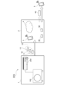
- FIG. 24 is a diagram showing an example of a refrigerant circuit when device 1 is a water heater.
- the same reference numerals are given to the components corresponding to the parts in FIG.
- the device 1 water heater
- the inlet and outlet temperatures T6' and T7' of the water circuit may be used.
- the examples of Mollier diagrams shown in FIGS. 5 and 6 differ depending on the type of refrigerant.
- the CO2 refrigerant used in water heaters becomes supercritical during operation, so there is no distinction between a liquid phase and a gas phase, but the relationship between pressure and enthalpy change is the same as the example shown in FIG.
- the refrigerant temperature in the gas cooler 205 portion cannot be measured, it can be converted from the refrigerant circulation amount, the water amount in the water circuit, the inlet/outlet temperatures T6' and T7' of the water circuit, and the heat exchange efficiency.
- the device management device 2 is the external terminal 3 or the cloud 4 , but it is not limited to this.
- the device management device 2 may be provided in the device 1 .
- a program for realizing the functions of the device management apparatus 2 is recorded in a computer-readable recording medium, and the program recorded in the recording medium is read by a computer system and executed. processing may be performed.
- the "computer system” here includes an OS and hardware such as peripheral devices.
- “computer-readable recording medium” refers to portable media such as flexible disks, magneto-optical disks, ROMs and CD-ROMs, and storage devices such as hard disks built into computer systems.
- “computer-readable recording medium” refers to a program that dynamically retains a program for a short period of time, like a communication line when transmitting a program via a network such as the Internet or a communication line such as a telephone line. volatile memory inside a computer system that is a server or a client in that case, which holds a program for a certain period of time.
- the program may be for realizing part of the functions described above, or may be capable of realizing the functions described above in combination with a program already recorded in the computer system.
- the above program may be stored in a predetermined server, and distributed (downloaded, etc.) via a communication line in response to a request from another device.
- part or all of the functions of the device management device 2 may be implemented as an integrated circuit such as an LSI (Large Scale Integration). Each function may be individually processorized, or part or all may be integrated and processorized. Also, the method of circuit integration is not limited to LSI, but may be realized by a dedicated circuit or a general-purpose processor. In addition, when an integration circuit technology that replaces LSI appears due to advances in semiconductor technology, an integrated circuit based on this technology may be used.
- LSI Large Scale Integration
Landscapes
- Engineering & Computer Science (AREA)
- General Engineering & Computer Science (AREA)
- Mechanical Engineering (AREA)
- Chemical & Material Sciences (AREA)
- Combustion & Propulsion (AREA)
- Signal Processing (AREA)
- Physics & Mathematics (AREA)
- Human Computer Interaction (AREA)
- Fuzzy Systems (AREA)
- Mathematical Physics (AREA)
- Health & Medical Sciences (AREA)
- Biomedical Technology (AREA)
- Thermal Sciences (AREA)
- Air Conditioning Control Device (AREA)
Priority Applications (6)
| Application Number | Priority Date | Filing Date | Title |
|---|---|---|---|
| DE112022006379.3T DE112022006379T5 (de) | 2022-01-13 | 2022-01-13 | Vorrichtungsmanagementsystem und Kältemittelmengeschätzverfahren |
| PCT/JP2022/000849 WO2023135696A1 (ja) | 2022-01-13 | 2022-01-13 | 機器管理システムおよび冷媒量推定方法 |
| JP2023573707A JP7601265B2 (ja) | 2022-01-13 | 2022-01-13 | 機器管理システムおよび冷媒量推定方法 |
| US18/573,537 US20240288190A1 (en) | 2022-01-13 | 2022-01-13 | Equipment management system and refrigerant amount estimation method |
| JP2024174366A JP7775958B2 (ja) | 2022-01-13 | 2024-10-03 | 機器管理システムおよび冷媒量推定方法 |
| JP2025127423A JP2025142332A (ja) | 2022-01-13 | 2025-07-30 | 機器管理システムおよび冷媒量推定方法 |
Applications Claiming Priority (1)
| Application Number | Priority Date | Filing Date | Title |
|---|---|---|---|
| PCT/JP2022/000849 WO2023135696A1 (ja) | 2022-01-13 | 2022-01-13 | 機器管理システムおよび冷媒量推定方法 |
Publications (1)
| Publication Number | Publication Date |
|---|---|
| WO2023135696A1 true WO2023135696A1 (ja) | 2023-07-20 |
Family
ID=87278654
Family Applications (1)
| Application Number | Title | Priority Date | Filing Date |
|---|---|---|---|
| PCT/JP2022/000849 Ceased WO2023135696A1 (ja) | 2022-01-13 | 2022-01-13 | 機器管理システムおよび冷媒量推定方法 |
Country Status (4)
| Country | Link |
|---|---|
| US (1) | US20240288190A1 (https=) |
| JP (3) | JP7601265B2 (https=) |
| DE (1) | DE112022006379T5 (https=) |
| WO (1) | WO2023135696A1 (https=) |
Citations (10)
| Publication number | Priority date | Publication date | Assignee | Title |
|---|---|---|---|---|
| JPS4635331Y1 (https=) * | 1969-02-28 | 1971-12-06 | ||
| JP2009079842A (ja) * | 2007-09-26 | 2009-04-16 | Mitsubishi Electric Corp | 冷凍サイクル装置およびその制御方法 |
| WO2010021101A1 (ja) * | 2008-08-19 | 2010-02-25 | ダイキン工業株式会社 | 診断支援装置 |
| JP2010048433A (ja) * | 2008-08-19 | 2010-03-04 | Daikin Ind Ltd | 診断支援装置 |
| WO2010113804A1 (ja) * | 2009-03-30 | 2010-10-07 | 三菱電機株式会社 | 冷凍サイクル装置 |
| WO2011111114A1 (ja) * | 2010-03-12 | 2011-09-15 | 三菱電機株式会社 | 冷凍空調装置 |
| JP2013250038A (ja) * | 2012-06-04 | 2013-12-12 | Daikin Industries Ltd | 冷凍装置管理システム |
| WO2014017161A1 (ja) * | 2012-07-23 | 2014-01-30 | 三菱電機株式会社 | 冷凍空調装置、冷媒漏洩検知装置及び冷媒漏洩検知方法 |
| WO2016174767A1 (ja) * | 2015-04-30 | 2016-11-03 | 三菱電機株式会社 | 冷凍サイクル装置及び冷凍サイクル装置の異常検知システム |
| JP2017026262A (ja) * | 2015-07-27 | 2017-02-02 | 東京電力ホールディングス株式会社 | 計測値処理装置及び計測方法 |
Family Cites Families (14)
| Publication number | Priority date | Publication date | Assignee | Title |
|---|---|---|---|---|
| JPH10176877A (ja) * | 1996-12-17 | 1998-06-30 | Hitachi Ltd | 冷媒封入量判定システム |
| JP3455046B2 (ja) * | 1997-01-22 | 2003-10-06 | シャープ株式会社 | 空気調和機の自動運転制御システム |
| JPH1163745A (ja) * | 1997-08-08 | 1999-03-05 | Hitachi Ltd | 空気調和機の冷媒封入量指示装置及び監視装置 |
| JP2005098642A (ja) | 2003-09-26 | 2005-04-14 | Hitachi Ltd | 冷凍空調機器及び冷凍空調システム |
| JP4110276B2 (ja) | 2003-10-03 | 2008-07-02 | 株式会社日立製作所 | 冷媒充填装置及び冷媒充填方法 |
| JP4075933B2 (ja) | 2006-01-30 | 2008-04-16 | ダイキン工業株式会社 | 空気調和装置 |
| JP2008025936A (ja) | 2006-07-24 | 2008-02-07 | Daikin Ind Ltd | 空気調和装置 |
| JP5058324B2 (ja) * | 2010-10-14 | 2012-10-24 | 三菱電機株式会社 | 冷凍サイクル装置 |
| JP5693328B2 (ja) | 2011-03-31 | 2015-04-01 | 中野冷機株式会社 | 冷凍装置及び冷凍装置の冷媒漏れ検知方法 |
| JP6147576B2 (ja) | 2013-06-05 | 2017-06-14 | 東北電力株式会社 | ヒートポンプ給湯装置の運転方法 |
| JP2019045035A (ja) | 2017-08-31 | 2019-03-22 | 株式会社富士通ゼネラル | 空気調和システム |
| US10782034B2 (en) * | 2017-12-13 | 2020-09-22 | RK Mechanical, Inc. | System for conditioning an airflow using a portable closed loop cooling system |
| JP2020153618A (ja) | 2019-03-22 | 2020-09-24 | Fptソフトウェアジャパン株式会社 | 空調制御サーバ装置、空調制御方法及び空調制御システム |
| JP7435156B2 (ja) | 2020-03-27 | 2024-02-21 | 株式会社富士通ゼネラル | 空気調和機 |
-
2022
- 2022-01-13 JP JP2023573707A patent/JP7601265B2/ja active Active
- 2022-01-13 DE DE112022006379.3T patent/DE112022006379T5/de active Pending
- 2022-01-13 US US18/573,537 patent/US20240288190A1/en active Pending
- 2022-01-13 WO PCT/JP2022/000849 patent/WO2023135696A1/ja not_active Ceased
-
2024
- 2024-10-03 JP JP2024174366A patent/JP7775958B2/ja active Active
-
2025
- 2025-07-30 JP JP2025127423A patent/JP2025142332A/ja active Pending
Patent Citations (10)
| Publication number | Priority date | Publication date | Assignee | Title |
|---|---|---|---|---|
| JPS4635331Y1 (https=) * | 1969-02-28 | 1971-12-06 | ||
| JP2009079842A (ja) * | 2007-09-26 | 2009-04-16 | Mitsubishi Electric Corp | 冷凍サイクル装置およびその制御方法 |
| WO2010021101A1 (ja) * | 2008-08-19 | 2010-02-25 | ダイキン工業株式会社 | 診断支援装置 |
| JP2010048433A (ja) * | 2008-08-19 | 2010-03-04 | Daikin Ind Ltd | 診断支援装置 |
| WO2010113804A1 (ja) * | 2009-03-30 | 2010-10-07 | 三菱電機株式会社 | 冷凍サイクル装置 |
| WO2011111114A1 (ja) * | 2010-03-12 | 2011-09-15 | 三菱電機株式会社 | 冷凍空調装置 |
| JP2013250038A (ja) * | 2012-06-04 | 2013-12-12 | Daikin Industries Ltd | 冷凍装置管理システム |
| WO2014017161A1 (ja) * | 2012-07-23 | 2014-01-30 | 三菱電機株式会社 | 冷凍空調装置、冷媒漏洩検知装置及び冷媒漏洩検知方法 |
| WO2016174767A1 (ja) * | 2015-04-30 | 2016-11-03 | 三菱電機株式会社 | 冷凍サイクル装置及び冷凍サイクル装置の異常検知システム |
| JP2017026262A (ja) * | 2015-07-27 | 2017-02-02 | 東京電力ホールディングス株式会社 | 計測値処理装置及び計測方法 |
Also Published As
| Publication number | Publication date |
|---|---|
| JP7601265B2 (ja) | 2024-12-17 |
| DE112022006379T5 (de) | 2024-10-24 |
| JP2025000974A (ja) | 2025-01-07 |
| US20240288190A1 (en) | 2024-08-29 |
| JP2025142332A (ja) | 2025-09-30 |
| JP7775958B2 (ja) | 2025-11-26 |
| JPWO2023135696A1 (https=) | 2023-07-20 |
Similar Documents
| Publication | Publication Date | Title |
|---|---|---|
| US20210207831A1 (en) | Refrigerant leak detection and mitigation | |
| US10775084B2 (en) | System for refrigerant charge verification | |
| US9310094B2 (en) | Portable method and apparatus for monitoring refrigerant-cycle systems | |
| JP4829147B2 (ja) | 空気調和設備 | |
| EP2071251A1 (en) | Air-conditioning control intermediate device, air-conditioning control system, air-conditioning control method, and air-conditioning control program | |
| EP2148147A2 (en) | Method of controlling air conditioner | |
| CN108758903B (zh) | 空调及其控制方法 | |
| JP7072398B2 (ja) | 一体型空気調和装置の管理装置および管理プログラム | |
| WO2010021101A1 (ja) | 診断支援装置 | |
| JP2010048433A (ja) | 診断支援装置 | |
| WO2020179088A1 (ja) | 空調管理装置、空調管理システム、空調管理方法及びプログラム | |
| Li et al. | Improving quick cooling performance of a R410A split air conditioner during startup by actively controlling refrigerant mass migration | |
| US20240310097A1 (en) | Equipment management system and management method | |
| JP2011214738A (ja) | ダクト循環方式空調システムにおけるエネルギー消費効率管理方法 | |
| JP6653588B2 (ja) | 冷房機、及び、空気調和機 | |
| JP2009041886A (ja) | 空調熱源設備の性能評価装置 | |
| JP5718629B2 (ja) | 冷媒量検知装置 | |
| US12578134B2 (en) | Air conditioner for removing foreign substances from indoor heat exchanger and method of operating the same | |
| WO2023135696A1 (ja) | 機器管理システムおよび冷媒量推定方法 | |
| JP4290705B2 (ja) | 空気調和機の診断方法及び診断システム | |
| JP7651016B2 (ja) | 機器管理システムおよび通知方法 | |
| KR102391331B1 (ko) | 공조 시스템 및 그 제어 방법 | |
| WO2015128899A1 (ja) | 空気調和装置 | |
| WO2019163042A1 (ja) | 空気調和装置およびエアハンドリングユニット | |
| CN114811743A (zh) | 一种空调系统及其室内机能力计算方法 |
Legal Events
| Date | Code | Title | Description |
|---|---|---|---|
| 121 | Ep: the epo has been informed by wipo that ep was designated in this application |
Ref document number: 22920221 Country of ref document: EP Kind code of ref document: A1 |
|
| WWE | Wipo information: entry into national phase |
Ref document number: 2023573707 Country of ref document: JP |
|
| WWE | Wipo information: entry into national phase |
Ref document number: 18573537 Country of ref document: US |
|
| WWE | Wipo information: entry into national phase |
Ref document number: 202427011647 Country of ref document: IN |
|
| WWE | Wipo information: entry into national phase |
Ref document number: 112022006379 Country of ref document: DE |
|
| 122 | Ep: pct application non-entry in european phase |
Ref document number: 22920221 Country of ref document: EP Kind code of ref document: A1 |