WO2023132244A1 - Joint soudé - Google Patents
Joint soudé Download PDFInfo
- Publication number
- WO2023132244A1 WO2023132244A1 PCT/JP2022/047151 JP2022047151W WO2023132244A1 WO 2023132244 A1 WO2023132244 A1 WO 2023132244A1 JP 2022047151 W JP2022047151 W JP 2022047151W WO 2023132244 A1 WO2023132244 A1 WO 2023132244A1
- Authority
- WO
- WIPO (PCT)
- Prior art keywords
- steel sheet
- phase
- plating layer
- concentration
- less
- Prior art date
Links
Images

Classifications
-
- B—PERFORMING OPERATIONS; TRANSPORTING
- B23—MACHINE TOOLS; METAL-WORKING NOT OTHERWISE PROVIDED FOR
- B23K—SOLDERING OR UNSOLDERING; WELDING; CLADDING OR PLATING BY SOLDERING OR WELDING; CUTTING BY APPLYING HEAT LOCALLY, e.g. FLAME CUTTING; WORKING BY LASER BEAM
- B23K11/00—Resistance welding; Severing by resistance heating
- B23K11/10—Spot welding; Stitch welding
- B23K11/11—Spot welding
-
- B—PERFORMING OPERATIONS; TRANSPORTING
- B23—MACHINE TOOLS; METAL-WORKING NOT OTHERWISE PROVIDED FOR
- B23K—SOLDERING OR UNSOLDERING; WELDING; CLADDING OR PLATING BY SOLDERING OR WELDING; CUTTING BY APPLYING HEAT LOCALLY, e.g. FLAME CUTTING; WORKING BY LASER BEAM
- B23K11/00—Resistance welding; Severing by resistance heating
- B23K11/16—Resistance welding; Severing by resistance heating taking account of the properties of the material to be welded
-
- C—CHEMISTRY; METALLURGY
- C21—METALLURGY OF IRON
- C21D—MODIFYING THE PHYSICAL STRUCTURE OF FERROUS METALS; GENERAL DEVICES FOR HEAT TREATMENT OF FERROUS OR NON-FERROUS METALS OR ALLOYS; MAKING METAL MALLEABLE, e.g. BY DECARBURISATION OR TEMPERING
- C21D8/00—Modifying the physical properties by deformation combined with, or followed by, heat treatment
- C21D8/02—Modifying the physical properties by deformation combined with, or followed by, heat treatment during manufacturing of plates or strips
-
- C—CHEMISTRY; METALLURGY
- C21—METALLURGY OF IRON
- C21D—MODIFYING THE PHYSICAL STRUCTURE OF FERROUS METALS; GENERAL DEVICES FOR HEAT TREATMENT OF FERROUS OR NON-FERROUS METALS OR ALLOYS; MAKING METAL MALLEABLE, e.g. BY DECARBURISATION OR TEMPERING
- C21D9/00—Heat treatment, e.g. annealing, hardening, quenching or tempering, adapted for particular articles; Furnaces therefor
- C21D9/46—Heat treatment, e.g. annealing, hardening, quenching or tempering, adapted for particular articles; Furnaces therefor for sheet metals
-
- C—CHEMISTRY; METALLURGY
- C22—METALLURGY; FERROUS OR NON-FERROUS ALLOYS; TREATMENT OF ALLOYS OR NON-FERROUS METALS
- C22C—ALLOYS
- C22C18/00—Alloys based on zinc
-
- C—CHEMISTRY; METALLURGY
- C22—METALLURGY; FERROUS OR NON-FERROUS ALLOYS; TREATMENT OF ALLOYS OR NON-FERROUS METALS
- C22C—ALLOYS
- C22C18/00—Alloys based on zinc
- C22C18/04—Alloys based on zinc with aluminium as the next major constituent
-
- C—CHEMISTRY; METALLURGY
- C22—METALLURGY; FERROUS OR NON-FERROUS ALLOYS; TREATMENT OF ALLOYS OR NON-FERROUS METALS
- C22C—ALLOYS
- C22C38/00—Ferrous alloys, e.g. steel alloys
-
- C—CHEMISTRY; METALLURGY
- C22—METALLURGY; FERROUS OR NON-FERROUS ALLOYS; TREATMENT OF ALLOYS OR NON-FERROUS METALS
- C22C—ALLOYS
- C22C38/00—Ferrous alloys, e.g. steel alloys
- C22C38/60—Ferrous alloys, e.g. steel alloys containing lead, selenium, tellurium, or antimony, or more than 0.04% by weight of sulfur
-
- C—CHEMISTRY; METALLURGY
- C23—COATING METALLIC MATERIAL; COATING MATERIAL WITH METALLIC MATERIAL; CHEMICAL SURFACE TREATMENT; DIFFUSION TREATMENT OF METALLIC MATERIAL; COATING BY VACUUM EVAPORATION, BY SPUTTERING, BY ION IMPLANTATION OR BY CHEMICAL VAPOUR DEPOSITION, IN GENERAL; INHIBITING CORROSION OF METALLIC MATERIAL OR INCRUSTATION IN GENERAL
- C23C—COATING METALLIC MATERIAL; COATING MATERIAL WITH METALLIC MATERIAL; SURFACE TREATMENT OF METALLIC MATERIAL BY DIFFUSION INTO THE SURFACE, BY CHEMICAL CONVERSION OR SUBSTITUTION; COATING BY VACUUM EVAPORATION, BY SPUTTERING, BY ION IMPLANTATION OR BY CHEMICAL VAPOUR DEPOSITION, IN GENERAL
- C23C2/00—Hot-dipping or immersion processes for applying the coating material in the molten state without affecting the shape; Apparatus therefor
- C23C2/04—Hot-dipping or immersion processes for applying the coating material in the molten state without affecting the shape; Apparatus therefor characterised by the coating material
- C23C2/06—Zinc or cadmium or alloys based thereon
-
- C—CHEMISTRY; METALLURGY
- C23—COATING METALLIC MATERIAL; COATING MATERIAL WITH METALLIC MATERIAL; CHEMICAL SURFACE TREATMENT; DIFFUSION TREATMENT OF METALLIC MATERIAL; COATING BY VACUUM EVAPORATION, BY SPUTTERING, BY ION IMPLANTATION OR BY CHEMICAL VAPOUR DEPOSITION, IN GENERAL; INHIBITING CORROSION OF METALLIC MATERIAL OR INCRUSTATION IN GENERAL
- C23C—COATING METALLIC MATERIAL; COATING MATERIAL WITH METALLIC MATERIAL; SURFACE TREATMENT OF METALLIC MATERIAL BY DIFFUSION INTO THE SURFACE, BY CHEMICAL CONVERSION OR SUBSTITUTION; COATING BY VACUUM EVAPORATION, BY SPUTTERING, BY ION IMPLANTATION OR BY CHEMICAL VAPOUR DEPOSITION, IN GENERAL
- C23C2/00—Hot-dipping or immersion processes for applying the coating material in the molten state without affecting the shape; Apparatus therefor
- C23C2/26—After-treatment
Definitions
- the present invention relates to a welded joint, and more particularly to a welded joint obtained by spot welding plated steel sheets.
- Patent Document 1 teaches addressing such LME cracking by improving the spot welding method. More specifically, in Patent Literature 1, after the energization between the welding electrodes is completed, the welding electrodes are kept under pressure (extending the post-welding holding time Ht), and the post-welding holding time Ht is Adjusting the thickness as a function of t allows the molten zinc-based coating to solidify before the electrode is opened, so that the molten zinc-based coating does not enter the grain boundaries of the steel sheet at locations where welding residual stress is high, preventing cracking. can be suppressed.
- Patent Document 2 teaches that cracks are suppressed by controlling the plating structure in the vicinity of spot welds after spot welding. More specifically, in Patent Document 2, a spot-welded member having a spot-welded portion formed by sandwiching and spot-welding a plate set in which a plurality of steel sheets are superimposed by a pair of electrodes, wherein the plurality of sheets At least one of the steel sheets is a high-strength zinc-based plated steel sheet having a tensile strength of 780 MPa or more, and the Al content in the coating of the high-strength zinc-based plated steel sheet is 0.5% by mass or more,
- the thermal shock region outside the corona bond end of the spot welded portion includes an FeAl alloy layer having an average thickness of 0.3 ⁇ m or more at the interface between the base steel plate of the high-strength zinc-based plated steel plate and the plating
- Patent Document 2 in order to suppress the penetration of Zn into the base steel sheet, the Al content in the coating is set to 0.5% by mass or more, so that the heat input during welding causes the separation of the steel sheet and the steel sheet. It is taught that it is important to form a high melting point FeAl alloy layer at the interface with the plating.
- Patent Documents 1 and 2 the suppression of LME cracking in welded joints is studied from the viewpoint of improving the spot welding method and controlling the plating structure in the vicinity of the spot welded portion after spot welding.
- Patent Literatures 1 and 2 do not necessarily conduct sufficient studies on suppressing the occurrence of LME cracks in welded joints in relation to the plating structure of the plated steel sheet before spot welding. Therefore, in the inventions described in these patent documents, there is still room for improvement regarding the improvement of LME resistance.
- an object of the present invention is to provide a welded joint capable of suppressing or reducing the occurrence of LME cracking during spot welding with a novel configuration.
- the present inventors focused particularly on the structure of the plating layer in the plated steel sheet used for welded joints. .
- the present inventors found that LME cracking occurs during spot welding by using a plated steel sheet having a coating layer in which the Al concentration distribution is appropriately controlled while containing a relatively small amount of Al.
- the inventors have found that it is possible to improve the structure of the plating layer in the part that is susceptible to corrosion, and in relation to this, it is possible to significantly improve the LME resistance of the welded joint, and have completed the present invention.
- the present invention that has achieved the above object is as follows. (1) a plurality of superimposed steel plates; A spot weld having a nugget for joining the plurality of steel plates, and a pressure weld zone and a heat affected zone formed around the nugget; A welded joint comprising a separation portion positioned around the pressure contact portion, At least one of the plurality of steel plates is a plated steel plate comprising a base steel plate and a plated layer formed on a surface of the base steel plate that corresponds to at least the overlapping surface of the plurality of steel plates.
- the plating layer in the separation portion outside the heat affected zone is, by mass%, Al: 0.10-1.50% and Fe: 0.01-2.00% and further Mg: 0-1.500%, Si: 0 to 1.000%, Ni: 0 to 1.000%, Ca: 0 to 4.000%, Sb: 0 to 0.500%, Pb: 0 to 0.500%, Cu: 0 to 1.000%, Sn: 0 to 1.000%, Ti: 0 to 1.000%, Cr: 0 to 1.000%, Nb: 0 to 1.000%, Zr: 0 to 1.000%, Mn: 0 to 1.000%, Mo: 0 to 1.000%, Ag: 0 to 1.000%, Li: 0 to 1.000%, La: 0 to 0.500%, Ce: 0 to 0.500%, B: 0 to 0.500%, Y: 0 to 0.500%, P: 0 to 0.500%, and Sr: 0 to 0.500% containing at least one of 5.000% or less
- the chemical composition contains 0.30 to 1.50% Al by mass, and the plated layer of the separation portion in a region of 500 ⁇ m from the end of the pressure contact portion contains ⁇ phase and ⁇
- the chemical composition contains 0.30 to 1.50% Al by mass, and the plated layer of the separation portion in a region of 500 ⁇ m from the end of the pressure contact portion contains ⁇ phase and ⁇
- the welded joint according to (1) above, wherein the ratio of the area ratio of the ⁇ phase to the total area ratio of the phases is 40 to 100%.
- a welded joint according to an embodiment of the present invention comprises a plurality of superimposed steel plates, A spot weld having a nugget for joining the plurality of steel plates, and a pressure weld zone and a heat affected zone formed around the nugget; A welded joint comprising a separation portion positioned around the pressure contact portion, At least one of the plurality of steel plates is a plated steel plate comprising a base steel plate and a plated layer formed on a surface of the base steel plate that corresponds to at least the overlapping surface of the plurality of steel plates.
- the plating layer in the separation portion outside the heat affected zone is, by mass%, Al: 0.10-1.50% and Fe: 0.01-2.00% and further Mg: 0-1.500%, Si: 0 to 1.000%, Ni: 0 to 1.000%, Ca: 0 to 4.000%, Sb: 0 to 0.500%, Pb: 0 to 0.500%, Cu: 0 to 1.000%, Sn: 0 to 1.000%, Ti: 0 to 1.000%, Cr: 0 to 1.000%, Nb: 0 to 1.000%, Zr: 0 to 1.000%, Mn: 0 to 1.000%, Mo: 0 to 1.000%, Ag: 0 to 1.000%, Li: 0 to 1.000%, La: 0 to 0.500%, Ce: 0 to 0.500%, B: 0 to 0.500%, Y: 0 to 0.500%, P: 0 to 0.500%, and Sr: 0 to 0.500% containing at least one of 5.000% or less
- LME cracking is caused by the tensile stress generated by welding, such as the pressure applied by the electrode or It is caused by tensile stress acting on the steel plate caused by many factors such as expansion and contraction of the weld zone and springback when the electrode is released. Therefore, the present inventors focused on the structure of the coating layer in the plated steel sheet in order to suppress or reduce the penetration of zinc into the steel sheet, and from the viewpoint of making the structure of the coating layer more appropriate. Study was carried out.
- the present inventors found that adding aluminum (Al) in a relatively small amount, ie, 0.10 to 1.50% by mass, in a coating layer mainly composed of zinc (Zn) is effective in reducing the amount of Zn inside the steel sheet. It was found that it is effective from the viewpoint of suppressing or reducing the invasion of When the amount of Al added increases, the composition of the plating layer approaches the Zn—Al eutectic composition, so the melting point of the plating layer decreases. Therefore, excessive addition of Al is highly likely to act disadvantageously from the viewpoint of suppressing or reducing the penetration of molten Zn into the steel sheet and improving the LME resistance.
- the present inventors have determined that the Al concentration distribution in the coating layer is such that the Al concentration at the center of the coating layer is the Al concentration near the interface between the base steel sheet and the coating layer, and more specifically, the Fe concentration is the base steel sheet.
- FIG. 1 is a view schematically showing a cross section of a welded joint according to an embodiment of the present invention, (a) is an overall view of the welded joint, and (b) is an end portion of a pressure contact portion and a separation immediately outside it. 2 is an enlarged view of the part;
- FIG. 1( a ) a welded joint 1 according to an embodiment of the present invention includes two superimposed steel plates 11 , a nugget 12 joining these steel plates 11 , and around the nugget 12
- a spot welded portion 16 having a pressure contact portion 13 and a heat affected zone 15 formed thereon, and a separation portion 17 positioned around the pressure contact portion 13 are provided.
- FIG. 1 is a view schematically showing a cross section of a welded joint according to an embodiment of the present invention, (a) is an overall view of the welded joint, and (b) is an end portion of a pressure contact portion and a separation immediately outside it. 2 is an enlarged view of the part;
- plated steel sheets provided with a coating layer mainly composed of Zn on both sides of a base steel sheet and having an Al concentration distribution controlled within a predetermined range are used.
- a plating layer 18 derived from the plating layer on the steel plate 11 before spot welding is formed in the separation portion 17 immediately outside the pressure contact portion end portion 14. .
- the structure of the initial plating layer changes due to the heat effect during spot welding, etc.
- a plated layer 18 having a relatively high ratio of ⁇ phase more specifically, a plated layer 18 having an area ratio of ⁇ phase with respect to the total area ratio of ⁇ phase and ⁇ phase is 10 to 100%.
- the ⁇ phase refers to a phase mainly composed of Zn and containing other elements such as Fe in a solid solution state.
- SEM-EPMA indicates a phase having a Zn concentration of 97 atomic % or more, an Fe concentration of 3 atomic % or less, and other elements of 3 atomic % or less.
- the ⁇ phase refers to a phase having a Zn concentration of 87 atomic % or more, an Fe concentration of 8 to 13 atomic %, and other impurities of 3 atomic % or less as measured by SEM-EPMA.
- Such changes in the structure of the coating layer are greatly affected by the chemical composition and structure of the initial coating layer before spot welding.
- the alloying of Zn in the coating layer progresses due to the heat input of welding, so that the proportion of ⁇ phase is generally high and the proportion of ⁇ phase is relatively low.
- the plating layer 18 having a relatively high proportion of the ⁇ phase is formed in the separation portion 17 immediately outside the pressure contact portion 13 as compared with the conventional spot welding of Zn-based plated steel sheets.
- the penetration of molten Zn into the steel sheet during spot welding is suppressed or reduced, and as a result, the LME resistance of the resulting welded joint can be significantly improved.
- FIG. 1 for ease of understanding, the case of a welded joint in which only two steel plates 11 are superimposed and a plating layer is formed on both steel plates 11 has been described, but welding according to the embodiment of the present invention
- the joint is not necessarily limited to such a welded joint, but may include various welded joints in which a plating layer 18 having a predetermined amount of ⁇ phase is formed at the separation 17 within the heat affected zone 15 .
- a plating layer 18 having a predetermined amount of ⁇ phase is formed at the separation 17 within the heat affected zone 15 .
- only one of the steel plates 11 may be a plated steel plate.
- the plating layer 18 only needs to be present in the separation portion 17 immediately outside the pressure contact portion 13 of at least the surface corresponding to the overlapping surface of the two surfaces of the plated steel sheet, and of course, the plating layer 18 is present on both surfaces. and/or there may be an initial plating layer associated with the plating layer 18 .
- the structure of the plating layer changes during spot welding, and a plating layer 18 having a relatively high proportion of ⁇ phase is formed. Therefore, it is possible to further improve the LME resistance as compared with the case where the plating layer 18 exists only on the surfaces corresponding to the overlapping surfaces of the steel sheets.
- welded joints of three or more steel plates may include various welded joints in which a plating layer 18 having a predetermined amount of ⁇ phase is formed at the separation portion 17 in the heat affected zone 15 .
- a plating layer 18 having a predetermined amount of ⁇ phase is formed at the separation portion 17 in the heat affected zone 15 .
- at least one of the three steel plates 11 has a plated separation portion 17 immediately outside the pressure contact portion 13 on the surface corresponding to the overlapping surface of one or more of the steel plates 11. It is sufficient if layer 18 is present.
- layer 18 is present.
- only the middle steel sheet 11 of the three superimposed steel sheets 11 is a plated steel sheet, only the separation portion 17 immediately outside the pressure contact portion 13 on one of the two surfaces of the plated steel sheet is plated.
- the layer 18 may be present, or the plating layer 18 may be present in the separation portion 17 immediately outside the pressure contact portion 13 on both surfaces.
- the plating layer 18 exists only in the separation portion 17 immediately outside the pressure contact portion 13 of some of the steel plates 11, and another Zn-based plating layer exists in the separation portion 17 immediately outside the pressure contact portion 13 of the other steel plates 11. You may have Such embodiments are also included in the present invention. In this case, compared to the case of welded joints in which the plating layer 18 exists in the separation portion 17 immediately outside the pressure contact portion 13 of all the steel plates 11, the risk of LME cracking increases on the surface where another Zn-based plating layer exists.
- the specific number and arrangement of the steel sheets 11 on which the plating layer 18 having a predetermined amount of ⁇ phase is formed in the welded joint although there is a possibility that the joint strength is somewhat reduced, the desired joint strength, etc. It may be determined appropriately in consideration of the above.
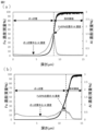
- FIG. 2 shows the results of GDS analysis of a plated steel sheet
- FIG. 2(a) shows the results of GDS analysis of an Al-containing plated steel sheet produced by a conventional method
- FIG. 4 shows GDS analysis results of plated steel sheets useful for use in welded joints according to embodiments.
- the Al concentration peak is relatively high, in the Al-containing plated steel sheet produced by the usual method, a larger amount of Al in the coating layer is consumed to form the Fe—Al barrier layer, resulting in a relatively high Al concentration peak. A thick Fe--Al barrier layer is formed. Therefore, in FIG. 2( a ), the Al concentration decreases greatly as it progresses from the vicinity of the interface between the base steel sheet and the coating layer to the coating surface side, and then becomes a substantially constant and very low value, and the Fe concentration decreases. It can be seen that the Al concentration shows a low value of about 0.1% at the plating layer center corresponding to the intermediate position between the plating layer position and the plating surface, which is 50% of .
- the Al phase present in the coating layer other than the Fe-Al barrier layer prevents molten Zn from penetrating into the steel sheet during spot welding. Considering that it plays a very important role in suppressing or reducing it, further investigation was carried out. As a result, the present inventors controlled the total amount of Al added to a relatively low amount of 1.50% by mass or less to suppress the deterioration of the LME resistance due to the decrease in the melting point of the plating layer.
- the ratio of "Al concentration at the center of the coating layer” / "Al concentration at the coating layer position where the Fe concentration is 50% of the base steel sheet” is controlled within the range of 0.10 to 1.50 by doing so, the inventors have found that the effect of adding Al to the plating layer can be sufficiently exhibited.
- the present inventors found that by using such a plated steel sheet, during spot welding, the separation portion in the heat-affected zone immediately outside the pressure contact portion, more specifically, 500 ⁇ m from the end of the pressure contact portion
- the structure of the initial plating layer changes in the separation part of the region, and a plating layer is formed in which the ratio of the area ratio of the ⁇ phase to the total area ratio of the ⁇ phase and the ⁇ phase is 10 to 100%.
- the present inventors have found that the corrosion resistance of the weld zone is significantly improved by increasing the ratio of the ⁇ phase, which is mainly composed of Zn, in the coating layer of the weld zone. I found that it can be done.
- Al in the initial plating layer acts as follows during spot welding. It is believed that this suppresses or reduces the intrusion of Zn, which has turned into a liquid phase due to the welding heat input, into the steel sheet along the grain boundaries.
- the Fe—Al barrier layer formed at the interface between the base steel sheet and the coating layer in the plated steel sheet is relatively fragile, the steel sheet may be damaged due to the pressure applied by the electrode during spot welding. It is considered that the material is relatively easily ruptured by the applied stress.
- the amount of Al in the entire plating layer is kept relatively low, while the amount of Al in the plating layer other than the Fe—Al barrier layer is increased.
- the plating structure of the plated steel sheet in the separation part of is changed to a structure with a relatively high proportion of ⁇ phase, and in relation to this, the penetration of molten Zn into the steel plate during spot welding can be suppressed or reduced.
- the corrosion resistance of the weld zone can also be improved has not been known in the past, and has been clarified for the first time by the inventors of the present invention.
- one or more of the plurality of superimposed steel plates correspond to the base material steel plate and, among the surfaces of the base material steel plate, at least the overlapping surfaces of the plurality of steel plates. It is a plated steel sheet provided with a plated layer formed on the surface.
- the plating layer of this plated steel sheet has the following chemical composition, which is the same as the initial chemical composition before spot welding, at the separation portion outside the heat affected zone.
- Al is an element that is effective in suppressing the intrusion of molten Zn into the steel sheet along the grain boundaries.
- the Al content is set to 0.10% or more.
- Al content is 0.12% or more, 0.15% or more, 0.18% or more, 0.20% or more, 0.25% or more, 0.30% or more, 0.35% or more, 0.40% 0.50% or more, 0.52% or more, 0.55% or more, 0.60% or more, 0.62% or more, 0.65% or more, or 0.70% or more.
- the Al content is set to 1.50% or less.
- Al content is 1.45% or less, 1.40% or less, 1.30% or less, 1.20% or less, 1.10% or less, 1.00% or less, 0.90% or less, or 0.80% It may be below.
- Fe for example, dissolves out of the base steel sheet into the plating bath, or reacts with Al during the plating process to form an Fe—Al barrier layer at the interface between the base steel sheet and the plating layer. It is an element that is unavoidably contained in the layer. Therefore, in the embodiment of the present invention, the Fe content in the plating layer is 0.01% or more. Fe content is 0.04% or more, 0.05% or more, 0.10% or more, 0.15% or more, 0.20% or more, 0.25% or more, 0.30% or more, 0.40% or more, or 0.50% or more.
- the Fe content in the plating layer is set to 2.00% or less.
- Fe content is 1.80% or less, 1.60% or less, 1.50% or less, 1.30% or less, 1.20% or less, 1.00% or less, 0.90% or less, 0.80% Below, it may be 0.70% or less or 0.60% or less.
- the basic chemical composition of the plating layer is as above. Furthermore, the plating layer is optionally Mg: 0 to 1.500%, Si: 0 to 1.000%, Ni: 0 to 1.000%, Ca: 0 to 4.000%, Sb: 0 to 0.500%, Pb: 0-0.500%, Cu: 0-1.000%, Sn: 0-1.000%, Ti: 0-1.000%, Cr: 0-1.000%, Nb: 0-1.000%, Zr: 0-1.000%, Mn: 0-1.000%, Mo: 0-1.000%, Ag: 0-1.000%, Li: 0-1 .000%, La: 0-0.500%, Ce: 0-0.500%, B: 0-0.500%, Y: 0-0.500%, P: 0-0.500%, and Sr: At least one of 0 to 0.500% may be contained.
- the total content of these optional elements is 5.000% or less from the viewpoint of sufficiently exhibiting the action and function of the above-mentioned basic components constituting the plating layer, especially Al.
- Optional elements totaling no more than 4.500%, no more than 4.000%, no more than 3.500%, no more than 3.000%, no more than 2.500%, no more than 2.000%, no more than 1.500% or 1 It may be 0.000% or less.
- Mg is an effective element for improving the corrosion resistance of the plating layer.
- the Mg content may be 0%, the Mg content is preferably 0.001% or more in order to obtain such effects.
- the Mg content may be 0.010% or more, 0.050% or more, or 0.100% or more.
- the Mg content is preferably 1.500% or less.
- the Mg content may be 1.200% or less, 1.000% or less, 0.800% or less, or 0.500% or less.
- Si is an effective element for improving the corrosion resistance of the plating layer.
- the Si content may be 0%, Si may be contained in the plating layer in an amount of 0.0001% or more or 0.001% or more, as required.
- excessive Si content may reduce the plating adhesion of the plating layer. Therefore, the Si content is preferably 1.000% or less.
- the Si content may be 0.800% or less, 0.500% or less, 0.100% or less, or 0.050% or less.
- Ni is an effective element for improving the corrosion resistance of the plating layer.
- the Ni content may be 0%, the Ni content is preferably 0.001% or more in order to obtain such effects.
- the Ni content may be 0.005% or more, 0.010% or more, or 0.020% or more.
- the Ni content is preferably 1.000% or less.
- the Ni content may be 0.800% or less, 0.600% or less, or 0.400% or less.
- Ca is an effective element for ensuring the wettability of the plating bath.
- the Ca content may be 0%, the Ca content is preferably 0.001% or more in order to obtain such effects.
- the Ca content may be 0.010% or more, 0.100% or more, or 1.000% or more.
- the Ca content is preferably 4.000% or less.
- the Ca content may be 3.000% or less, 2.000% or less, or 1.500% or less.
- the content of Sb, Pb, La, Ce, B, Y, P and Sr is preferably 0.500% or less, for example 0.300% or less, 0.100% or less or 0.050% or less may be Similarly, the content of Cu, Sn, Ti, Cr, Nb, Zr, Mn, Mo, Ag and Li is preferably 1.000% or less, for example 0.800% or less, 0.500% or less, or It may be 0.100% or less.
- the balance other than the above elements consists of Zn and impurities.
- Impurities in the plating layer are components and the like that are mixed due to various factors in the manufacturing process, including raw materials, when manufacturing the plating layer.
- the chemical composition of the plating layer is determined by dissolving the plating layer in an acid solution containing an inhibitor that suppresses the corrosion of the base steel sheet, and measuring the resulting solution by ICP (inductively coupled plasma) emission spectroscopy. be able to.
- the plating layer may be any plating layer having the chemical composition described above and is not particularly limited, but is preferably a hot-dip galvanized (GI) layer, for example.
- GI hot-dip galvanized
- the Fe content in the coating layer increases, and the final coating layer has the desired chemical composition and "Al concentration in the center of the coating layer" / "Fe concentration is the base material steel sheet In some cases, it may not be possible to obtain a ratio of "Al concentration at the plating layer position" that is 50% of.
- the thickness of the plating layer may be, for example, 3 to 50 ⁇ m.
- the coating weight of the plating layer is not particularly limited, but may be, for example, 10 to 170 g/m 2 per side.
- the adhesion amount of the plating layer is determined by dissolving the plating layer in an acid solution to which an inhibitor is added to suppress corrosion of the base steel sheet, and from the change in weight before and after pickling.
- the ratio of the area ratio of the ⁇ phase to the total area ratio of the ⁇ phase and the ⁇ phase is 10 to 100%. Since the region of 500 ⁇ m from the end of the press-contact portion corresponds to the region within the heat-affected zone, the heat input during spot welding generally facilitates the alloying of Zn in the coating layer in this region.
- the plating layer has a high proportion of the ⁇ phase and a relatively low proportion of the ⁇ phase, which is mainly composed of Zn (Zn concentration of 97 atomic % or more).
- the ⁇ phase A plating layer having a relatively high ratio of is formed, specifically, a plating layer having a ratio of the area ratio of the ⁇ phase to the total area ratio of the ⁇ phase and the ⁇ phase of 10% or more as described above.
- the fact that the proportion of ⁇ phase is relatively high suggests that Zn alloying does not proceed sufficiently even with the heat input of spot welding. It can be said that this suggests that direct contact is suppressed or reduced.
- the intrusion of molten Zn into the steel sheet during spot welding is suppressed or reduced, so that the LME resistance of the resulting welded joint can be improved. Therefore, from the viewpoint of improving the LME resistance of the welded joint and further the corrosion resistance of the weld zone, the higher the ratio of the ⁇ phase in the coating layer in the separation part immediately outside the pressure contact part, the better.
- the ratio of the area ratio of the ⁇ phase to the sum of the area ratios of the ⁇ phase and the ⁇ phase is preferably 15% or more, more preferably 25% or more, and most preferably 40% or more. % or more or 70% or more.
- the proportion of the ⁇ phase can be increased by increasing the Al content of the entire coating layer and applying a method for manufacturing a plated steel sheet, which will be described later in detail.
- the Al content of the entire plating layer should be 0.30% or more. is preferred.
- the upper limit can be appropriately set within a range of 100% or less.
- the ratio of the area ratio of the ⁇ phase to the sum of the area ratios of the ⁇ phase and the ⁇ phase may be 95% or less, 90% or less, 85% or less, or 80% or less.
- the structure of the plating layer in the separation portion immediately outside the pressure contact portion is mainly composed of the ⁇ phase and the ⁇ phase.
- the total area ratio of the ⁇ phase and the ⁇ phase may be 70% or more or 80% or more.
- the sum of the area ratios of ⁇ phase and ⁇ phase may be 100% or less, 95% or less, or 90% or less.
- the ratio of the ⁇ phase in the separation portion in the region of 500 ⁇ m from the end of the pressure contact portion is determined as follows. First, a cross-sectional sample of the spot welded portion is prepared, and then a backscattered electron image (BSE image) including the end of the pressure welded portion is obtained by a scanning electron microscope with an electron probe microanalyzer (SEM-EPMA). The end of the pressure contact portion of the welded portion and a region of 500 ⁇ m from the end of the pressure contact portion toward the separation portion (boundary portion between the pressure contact portion and the separation portion) are specified.
- BSE image backscattered electron image
- SEM-EPMA electron probe microanalyzer
- the ⁇ phase has a Zn concentration of 97 atomic % or more, an Fe concentration of 3 atomic % or less, and other impurities of 3 atomic % or less
- the ⁇ phase has a Zn concentration of 87 atomic % or more and an Fe concentration of A phase containing 8 to 13 atomic % and 3 atomic % or less of other impurities.
- the field of view of the SEM image is 100 ⁇ m ⁇ 100 ⁇ m, and the same elemental analysis is performed on five different points in the boundary, and the ratio of the area ratio of ⁇ phase to the total area ratio of ⁇ phase and ⁇ phase is obtained in each field of view. Finally, by averaging them, the ratio of the area ratio of the ⁇ phase to the sum of the area ratios of the ⁇ phase and the ⁇ phase is determined.
- the purpose of suppressing or reducing the occurrence of LME cracking during spot welding is to determine the chemical composition of the coating layer and the ratio of ⁇ phase in the coating layer in the separation portion immediately outside the pressure contact portion.
- the above GDS requirement is not an essential technical feature for achieving the object of the present invention, but is a preferred means for reliably controlling the ratio of the ⁇ phase in the plating layer of the separation portion within a desired range. It's just one of us.
- the ratio of "Al concentration at the center of the plating layer"/"Al concentration at the position of the plating layer where the Fe concentration is 50% of the base material steel sheet" is, for example, 0.15 or more, 0.20 or more, 0.20 or more. It may be 30 or more, 0.40 or more, or 0.50 or more.
- the ratio of "Al concentration at the center of the plating layer” / "Al concentration at the position of the plating layer where the Fe concentration is 50% of the base steel sheet” is 1.40 or less, 1.30 or less, 1.20 or less, It may be 1.10 or less or 1.00 or less.
- the Al concentration at a depth position where the Fe strength is 50% of the Fe strength of the base steel sheet (Fe strength at a depth of 100 ⁇ m from the surface of the plating layer of the sample) in GDS measurement is defined as "Fe concentration is The Al concentration at the coating layer position that is 50% of the base steel sheet", and the distance from this depth position to the surface is defined as the thickness of the coating layer.
- the Al concentration by GDS at the 1/2 position of the thickness of the plating layer is determined as the “Al concentration at the center of the plating layer”, and finally the “Al concentration at the center of the plating layer” / “Fe concentration is 50 of the base steel sheet.
- the ratio of the Al concentration at the plating layer position is determined.
- the base material steel sheet for forming the plating layer is not particularly limited and may be any suitable material, particularly cold-rolled steel sheet.
- the base steel sheet may be a material having a chemical composition such that the plated steel sheet has a tensile strength of 780 MPa or more.
- LME cracking becomes conspicuous when steel sheets having relatively high strength are spot-welded, and that the higher the strength of the steel sheet, the higher the susceptibility to LME cracking. Therefore, when a plated steel sheet having a high tensile strength of 780 MPa or more is used in welded joints, the effect of suppressing LME cracking is particularly remarkable.
- an object of the present invention is to provide a welded joint capable of suppressing or reducing the occurrence of LME cracking during spot welding, wherein at least one of a plurality of superimposed steel plates is a plated steel sheet having a plating layer on at least the surface corresponding to the overlapping surface, and the plating layer is controlled to have a predetermined chemical composition in the separation part outside the heat affected zone, and a distance of 500 ⁇ m from the end of the pressure contact part
- the object is achieved by controlling the ratio of the ⁇ phase area ratio of the plating layer in the separation part of the region within the range of 10 to 100% with respect to the total area ratio of the ⁇ phase and the ⁇ phase. be.
- the base material steel plate is mass %, C: 0.01 to 0.50%, Si: 0.01 to 3.50%, Mn: 0.10-5.00%, P: 0.100% or less, S: 0.0300% or less, N: 0.0100% or less, O: 0 to 0.020%, Al: 0 to 1.000%, B: 0 to 0.010%, Nb: 0 to 0.150%, Ti: 0 to 0.20%, Mo: 0-3.00%, Cr: 0 to 2.00%, V: 0 to 1.00%, Ni: 0 to 2.00%, W: 0 to 1.00%, Ta: 0 to 0.10%, Co: 0 to 3.00%, Sn: 0 to 1.00%, Sb: 0 to 0.50%, Cu: 0 to 2.00%, As: 0 to 0.050%, Mg: 0-0.100%, Ca: 0-0.100%, Zr: 0 to 0.100%, Hf: 0 to 0.100%, It
- C is an element that increases the tensile strength at low cost and is an important element for controlling the strength of steel.
- the C content is preferably 0.01% or more.
- C content may be 0.05% or more, 0.08% or more, 0.09% or more, 0.10% or more, 0.11% or more, 0.12% or more, or 0.15% or more .
- an excessive C content may lead to a decrease in elongation. Therefore, the C content is preferably 0.50% or less.
- the C content may be 0.40% or less, 0.35% or less, or 0.30% or less.
- Si is an element that acts as a deoxidizing agent and suppresses the precipitation of carbides during the cooling process during cold-rolled sheet annealing.
- the Si content is preferably 0.01% or more.
- the Si content may be 0.10% or more, 0.12% or more, 0.15% or more, 0.30% or more, or 0.80% or more.
- an excessive Si content may increase the strength of the steel and decrease the elongation. Therefore, the Si content is preferably 3.50% or less.
- the Si content may be 2.50% or less, 2.00% or less, or 1.50% or less.
- Mn is an element that affects the ferrite transformation of steel and is an element that is effective in increasing strength. In order to sufficiently obtain such effects, the Mn content is preferably 0.10% or more. The Mn content may be 0.50% or more, 1.00% or more, or 1.50% or more. On the other hand, an excessive Mn content may increase the strength of the steel and decrease the elongation. Therefore, the Mn content is preferably 5.00% or less. The Mn content may be 4.00% or less, 3.00% or less, or 2.50% or less.
- P is an element that segregates at grain boundaries and promotes embrittlement of steel. Since the P content is preferably as small as possible, it is ideally 0%. However, an excessive reduction in P content may lead to a significant increase in cost. Therefore, the P content may be 0.0001% or more, 0.001% or more, or 0.005% or more. On the other hand, an excessive P content may cause embrittlement of the steel due to grain boundary segregation as described above. Therefore, the P content is preferably 0.100% or less. The P content may be 0.050% or less, 0.030% or less, or 0.010% or less.
- S is an element that forms non-metallic inclusions such as MnS in steel and causes a decrease in ductility of steel parts.
- the S content is 0% because the smaller the S content, the better.
- the S content may be 0.0001% or more, 0.0002% or more, 0.0010% or more, or 0.0050% or more.
- an excessive S content may cause cracks starting from non-metallic inclusions during cold forming. Therefore, the S content is preferably 0.0300% or less.
- the S content may be 0.0200% or less, 0.0150% or less, or 0.0100% or less.
- N is an element that forms coarse nitrides in the steel sheet and reduces the workability of the steel sheet.
- the N content is 0% because the smaller the N content, the better.
- the N content may be 0.0001% or more, 0.0005% or more, or 0.0010% or more.
- the N content is preferably 0.0100% or less.
- the N content may be 0.0080% or less or 0.0050% or less.
- the preferred basic chemical composition of the base steel sheet is as described above. Furthermore, the base material steel plate, if necessary, replaces part of the remaining Fe with O: 0 to 0.020%, Al: 0 to 1.000%, B: 0 to 0.010%, Nb : 0-0.150%, Ti: 0-0.20%, Mo: 0-3.00%, Cr: 0-2.00%, V: 0-1.00%, Ni: 0-2.
- the balance other than the above elements consists of Fe and impurities.
- Impurities in the base steel sheet are components that are mixed due to various factors in the manufacturing process, including raw materials such as ores and scraps, when the base steel sheet is industrially manufactured.
- the chemical composition of the base steel sheet can be measured by a general analytical method.
- the chemical composition of the base steel sheet may be measured by first removing the plating layer by mechanical grinding and then using Inductively Coupled Plasma-Atomic Emission Spectrometry (ICP-AES).
- C and S can be measured using a combustion-infrared absorption method
- N can be measured using an inert gas fusion-thermal conductivity method
- O can be measured using an inert gas fusion-nondispersive infrared absorption method.
- the plate thickness of the base steel plate is not particularly limited, but is, for example, 0.2 mm or more, and may be 0.3 mm or more, 0.6 mm or more, 1.0 mm or more, or 2.0 mm or more.
- the plate thickness of the base steel plate is, for example, 6.0 mm or less, and may be 5.0 mm or less or 4.0 mm or less.
- Galvanized steel sheets useful for use in welded joints according to embodiments of the present invention may have any suitable tensile strength, and preferably have a tensile strength of, for example, 780 MPa or greater, but are not particularly limited. .
- LME cracking becomes conspicuous when steel sheets having relatively high strength are spot-welded. Therefore, when the plated steel sheet has a high tensile strength of 780 MPa or more, the effect of suppressing LME cracking is particularly remarkable as compared with conventional plated steel sheets having the same tensile strength.
- the plated steel sheet may have a tensile strength of 980 MPa or higher, 1080 MPa or higher, or 1180 MPa or higher.
- the upper limit is not particularly limited, for example, the tensile strength of the plated steel sheet may be 2300 MPa or less, 2000 MPa or less, 1800 MPa or less, or 1500 MPa or less.
- Tensile strength is measured by taking a JIS No. 5 test piece from a direction in which the longitudinal direction of the test piece is parallel to the rolling direction of the plated steel sheet, and performing a tensile test in accordance with JIS Z 2241:2011.
- the plated steel sheet useful for use in the welded joint according to the embodiment of the present invention more specifically, when measured by glow discharge optical emission spectroscopy (GDS), the "Al concentration at the center of the plating layer"
- GDS glow discharge optical emission spectroscopy
- a preferred method for producing a plated steel sheet provided with a plating layer having a ratio of 0.10 to 1.50 of /"Al concentration at the position of the plating layer where the Fe concentration is 50% of the base steel sheet" will be described.
- the following description is intended to exemplify a characteristic method for manufacturing the plated steel sheet, and is intended to limit the plated steel sheet to those manufactured by the manufacturing method described below. not something to do.
- a plated steel sheet is produced by, for example, a casting process in which molten steel with an adjusted chemical composition is cast to form a billet, a hot rolling process in which the steel billet is hot rolled to obtain a hot rolled steel sheet, and a coiling process in which the hot rolled steel sheet is coiled. , a cold-rolling step of cold-rolling the coiled hot-rolled steel sheet to obtain a cold-rolled steel sheet, a pretreatment step, an annealing step of annealing the pre-treated cold-rolled steel sheet, and forming a coating layer on the obtained base steel sheet. It can be manufactured by performing a plating process to do. Alternatively, the cold rolling process may be performed as it is after pickling without winding after the hot rolling process. Each step will be described in detail below.
- Conditions for the casting process are not particularly limited. For example, following smelting using a blast furnace, an electric furnace, etc., various secondary smelting may be performed, and then casting may be performed by a method such as ordinary continuous casting or casting by an ingot method.
- a hot-rolled steel sheet can be obtained by hot-rolling the cast steel slab.
- the hot-rolling process is performed by hot-rolling a cast steel slab directly or by reheating it after cooling it once.
- the heating temperature of the billet may be, for example, 1100-1250.degree.
- rough rolling and finish rolling are usually performed.
- the temperature and rolling reduction for each rolling can be appropriately determined according to the desired metal structure and plate thickness.
- the finishing temperature of finish rolling may be 900 to 1050° C., and the rolling reduction of finish rolling may be 10 to 50%.
- a hot-rolled steel sheet can be coiled at a predetermined temperature.
- the coiling temperature can be appropriately determined depending on the desired metal structure and the like, and may be, for example, 500 to 800.degree.
- the hot-rolled steel sheet may be subjected to a predetermined heat treatment by unwinding before or after winding. Alternatively, the coiling process may not be performed, and after the hot rolling process, pickling may be performed and the cold rolling process described below may be performed.
- the hot-rolled steel sheet After subjecting the hot-rolled steel sheet to pickling or the like, the hot-rolled steel sheet can be cold-rolled to obtain a cold-rolled steel sheet.
- the rolling reduction of cold rolling can be appropriately determined according to the desired metal structure and plate thickness, and may be, for example, 20 to 80%.
- air cooling may be performed to cool to room temperature.
- Pretreatment process it is effective to perform a predetermined pretreatment process before annealing the cold-rolled steel sheet.
- pretreatment steps may include degreasing and optional grinding.
- the degreasing treatment may include, for example, electrifying the cold-rolled steel sheet in a solution of pH 8.0 or higher (electrolytic treatment).
- the current density during energization may be 1.0 to 8.0 A/dm 2 and the energization time may be 5 to 10 seconds.
- the optional grinding process is preferably carried out with heavy grinding brushes.
- the nucleation of the Fe-Al barrier layer is promoted during the plating process after the annealing process, and the Fe-Al barrier layer is densified. and the associated slow growth rate of the Fe—Al barrier layer, which allows its thickness to be reduced.
- the amount of Al consumed for forming the Fe--Al barrier layer can be reduced. Therefore, since the amount of Al in the plating layers other than the Fe—Al barrier layer can be increased, the finally obtained plated steel sheet has the ratio of "Al concentration at the center of the plating layer"/"Fe concentration of 50% of the base material steel sheet".
- the ratio of "Al concentration at the plating layer position" can be increased.
- the grinding treatment is not particularly limited, but can be performed, for example, by grinding the surface of the cold-rolled steel sheet with a heavy grinding brush under conditions of a grinding amount of 10 to 200 g/m 2 .
- the amount of grinding by the heavy grinding brush can be adjusted by any appropriate method known to those skilled in the art, and is not particularly limited. can be adjusted by appropriately selecting
- Annealing is performed on the cold-rolled steel sheet that has undergone the pretreatment process.
- the holding temperature in the annealing step is preferably 700-900°C. If the holding temperature in the annealing step is higher than 900°C, an external oxide layer may form on the surface of the steel sheet, degrading the plateability.
- the rate of temperature increase to the holding temperature is not particularly limited, but may be 1 to 10° C./sec.
- the retention time at the above retention temperature is preferably 10 to 300 seconds, more preferably 80 to 120 seconds. If the holding time is longer than 300 seconds, the external oxide may grow excessively and the plating properties may deteriorate.
- the dew point of the atmosphere in the annealing step is preferably -20 to 10°C, more preferably -10 to 5°C. If the dew point is too low, an external oxide layer may be formed on the surface of the steel sheet, degrading the platability. On the other hand, if the dew point is too high, Fe oxide may be similarly generated as an external oxide on the surface of the steel sheet, resulting in deterioration of the plateability.
- the atmosphere in the annealing step may be a reducing atmosphere, more specifically a reducing atmosphere containing nitrogen and hydrogen, such as a reducing atmosphere containing 1-10% hydrogen (eg, 4% hydrogen and nitrogen balance).
- a plating layer having the chemical composition and structure described above is formed on at least one, preferably both surfaces of the cold-rolled steel sheet (base material steel sheet). More specifically, the plating step is performed by hot-dip plating using a plating bath whose composition is adjusted so that the chemical composition of the plating layer is within the range described above.
- the time from immersing the steel sheet in the plating bath to the start of cooling is controlled to 6 seconds or less, and then the average cooling rate from the bath temperature (eg, 420 to 480 ° C.) to 370 ° C. is 20 ° C. /sec or more is extremely important.
- the Fe—Al barrier layer can be made thinner and the amount of Al consumed to form the Fe—Al barrier layer can be reduced. It becomes possible to sufficiently secure the amount of Al present in the.
- the ratio of "Al concentration at the center of the plating layer" / "Al concentration at the position of the plating layer where the Fe concentration is 50% of the base steel sheet” is set to 0.10 or more. be able to.
- the time from the start of immersion of the steel sheet in the plating bath to the start of cooling exceeds 6 seconds and/or the average cooling rate from the bath temperature to 370 ° C.
- the time from the start of immersion of the steel sheet in the plating bath to the start of cooling be shorter and the average cooling rate from the bath temperature to 370° C. be faster.
- the Al content of the entire plating layer is 0.30% or more
- the time from the start of immersion of the steel sheet in the plating bath to the start of cooling is 4 seconds or less
- the average cooling rate from the bath temperature to 370 ° C. is 40. C./sec or higher can further improve the LME resistance of the welded joint.
- the time from the start of immersion of the steel sheet in the plating bath to the start of cooling is 6 seconds or less, and the average cooling rate from the bath temperature to 370 ° C.
- the Al content of the entire plating layer is set to 0.30% or more, grinding treatment is performed with a heavy grinding brush as the pretreatment step described above, and cooling is started from the start of immersion of the steel sheet in the plating bath.
- the lower limit of the time from the start of immersion of the steel sheet in the plating bath to the start of cooling is not particularly limited, but for example, the time from the start of immersion of the steel sheet in the plating bath to the start of cooling may be 2 seconds or more.
- the upper limit of the average cooling rate from the bath temperature to 370°C is not particularly limited, but for example, the average cooling rate from the bath temperature to 370°C may be 80°C/sec or less.
- Other conditions of the plating process may be appropriately set in consideration of the thickness and adhesion amount of the plating layer.
- the coating amount of the coating layer is within a predetermined range, such as , can be adjusted within the range of 10 to 170 g/m 2 per side.
- the ratio of "Al concentration at the center of the plating layer” / "Al concentration at the position of the plating layer where the Fe concentration is 50% of the base steel sheet” is 0.10 to 1.50. Since it is controlled within the range, when used in spot welding, the structure of the initial plating layer changes in the separation part in the region of 500 ⁇ m from the end of the pressure contact part, and the total area ratio of ⁇ phase and ⁇ phase A coating layer having an area ratio of ⁇ phase of 10 to 100% is formed, and in relation to this, it is possible to remarkably suppress or reduce penetration of molten Zn into the steel sheet during spot welding.
- any appropriate steel sheet or plated steel sheet can be used as the steel sheet other than the plated steel sheet described above among the plurality of steel sheets used in the welded joint according to the embodiment of the present invention.
- Such a steel sheet may have, for example, a tensile strength of 780 MPa or more like the preferred embodiment of the plated steel sheet, or may have a tensile strength of less than 780 MPa. Therefore, as for steel sheets other than the plated steel sheets described above, an appropriate steel sheet or plated steel sheet may be appropriately selected according to the use of the welded joint and desired properties, such as desired joint strength.
- the welded joint according to the embodiment of the present invention uses the above-described plated steel sheet in all steel sheets, and uses the above-described plated steel sheet in a plurality of steel sheets that are superimposed or one or more steel sheets, and the plated steel sheet is used. It can be manufactured by applying any suitable spot welding method known to those skilled in the art to a plurality of steel sheets stacked with other steel sheets or other plated steel sheets. For example, a plurality of steel plates stacked as described above are pressurized using a pair of electrodes facing each other, and an electric current is passed between the electrodes under normal conditions to form a nugget and a press-contact portion around it.
- the spot welding conditions may be any suitable conditions known to those skilled in the art.
- the welding electrode may be a dome radius type welding electrode with a tip diameter of 6 to 8 mm, a pressure of 1.5 to 6.0 kN, an energization time of 0.1 to 1.0 s (5 to 50 cycles, power supply frequency of 50 Hz), an applied current of 4 to 15 kA, and a striking angle (the angle between the axial direction of the electrode and the direction perpendicular to the surface of the steel sheet) of 0 to 10°.
- the effect of adding Al to the coating layer is fully exhibited, and the ratio of the ⁇ phase in the coating layer in the separation portion immediately outside the pressure contact portion is adjusted to the desired value. It can be controlled within the range, and in relation to this, it becomes possible to suppress or reduce the intrusion of molten Zn into the inside of the steel sheet during spot welding. Therefore, such a welded joint is more advantageous than using a conventional plated steel sheet with a coating layer having a similar chemical composition, more specifically a Zn-based coating layer having a similar Al content. This makes it possible to achieve better LME resistance, and contributes to the development of industry through improved crash safety and longer life, particularly in the automotive field.
- the obtained cold-rolled steel sheet is subjected to a pretreatment in which a current density of 5.0 A/dm 2 is applied for 8 seconds in a pH 9.2 solution.
- a heavy grinding brush (D-100 manufactured by Hotani Co., Ltd.) was used to grind the cold-rolled steel sheet with a grinding amount of 10 to 200 g / m 2 , a brush reduction of 2.0 mm, and a rotation speed of 600 rpm.
- the surface was ground to introduce strain into the surface of the cold-rolled steel sheet.
- Table 1 shows whether or not each cold-rolled steel sheet was ground with a heavy grinding brush.
- each cold-rolled steel sheet was cut into a size of 100 mm ⁇ 200 mm, and then subjected to annealing treatment (annealing atmosphere: hydrogen 4% and nitrogen balance) under the conditions of a dew point of 0 ° C., a holding temperature of 870 ° C., and a holding time of 100 seconds. rice field. All the steel plate samples were annealed at a heating rate of 5° C./sec.
- the cut steel plate sample was treated with a hot dip galvanizing bath having a predetermined bath composition, and the bath temperature shown in Table 1, the time from immersion in the plating bath to the start of cooling, and the average cooling rate from the bath temperature to 370 ° C.
- a plated steel plate sample having a plated layer formed on both surfaces of the steel plate sample was obtained. After immersion in the plating bath, the steel plate sample was pulled up and adjusted to 50 g/m 2 per side by N 2 gas wiping before starting cooling. In Comparative Example 28, an alloying heat treatment was performed at 520° C. for 10 seconds after the hot-dip galvanizing treatment.
- a plated steel sheet sample was cut into a size of 50 mm ⁇ 50 mm, and then the GDS measurement was performed on the cut plated steel sheet sample to obtain an Al concentration distribution from the surface of the coating layer to a depth of 100 ⁇ m.
- the Al concentration at a depth position where the Fe strength is 50% of the Fe strength of the base steel sheet (Fe strength at a depth of 100 ⁇ m from the surface of the plating layer of the sample) in GDS measurement is defined as "Fe concentration is Al concentration at the coating layer position which is 50% of the base material steel plate", and the distance from this depth position to the surface was defined as the thickness of the coating layer.
- the Al concentration by GDS at the 1/2 position of the thickness of the plating layer is determined as the “Al concentration at the center of the plating layer”, and finally the “Al concentration at the center of the plating layer” / “Fe concentration is 50 of the base steel sheet. %, the ratio of the Al concentration at the plating layer position was determined. As a result, in the plated steel sheet samples of all examples (invention examples), the ratio of "Al concentration at the center of the plating layer"/"Al concentration at the position of the plating layer where the Fe concentration is 50% of the base material steel sheet" was 0. It was controlled within the range of 10 to 1.50.
- a plated steel plate sample with a size of 100 ⁇ 100 mm was subjected to spot welding.
- Two sheets of 50 mm ⁇ 100 mm were cut to a size of 50 mm ⁇ 100 mm, and a dome radius welding electrode with a tip diameter of 8 mm was used for these two plated steel sheets, with a striking angle of 5 ° and a pressure of 4.0 kN.
- the chemical composition of the plating layer was determined by immersing a 30 mm ⁇ 30 mm sample taken from the separation part outside the heat-affected zone of the welded joint in a 10% HCl aqueous solution containing an inhibitor (IBIT manufactured by Asahi Chemical Industry Co., Ltd.) and pickling the plating layer. After stripping, the plating components dissolved in the aqueous solution were determined by measuring by ICP emission spectroscopy. Table 1 shows the results.
- the ratio of the ⁇ phase in the separation portion in the region of 500 ⁇ m from the end of the pressure contact portion was determined as follows. First, a cross-sectional sample of the spot welded portion is prepared, and then a BSE image including the end of the pressure contact portion is obtained by SEM-EPMA. A 500 ⁇ m region (boundary portion between the pressure contact portion and the separation portion) was specified from the . Next, an elemental analysis was performed on the identified boundary to identify the area ratio of the ⁇ phase and the area ratio of the ⁇ phase at the boundary.
- the ⁇ phase has a Zn concentration of 97 atomic % or more, an Fe concentration of 3 atomic % or less, and other impurities of 3 atomic % or less, and the ⁇ phase has a Zn concentration of 87 atomic % or more and an Fe concentration of A phase containing 8 to 13 atomic % and 3 atomic % or less of other impurities was used.
- the field of view of the SEM image was 100 ⁇ m ⁇ 100 ⁇ m, and the same elemental analysis was performed on five different points in the boundary, and the ratio of the area ratio of the ⁇ phase to the total area ratio of the ⁇ phase and the ⁇ phase was obtained in each field of view. .
- the ratio of the area ratio of the ⁇ phase to the sum of the area ratios of the ⁇ phase and the ⁇ phase was determined.
- the total area ratio of the ⁇ phase and the ⁇ phase in the separation portion in the region of 500 ⁇ m from the end of the pressure contact portion was 80% or more.
- Comparative Example 26 since the Al content of the entire plating layer was low, the effect of suppressing LME cracking due to the addition of Al could not be sufficiently exhibited, and the LME resistance decreased.
- Comparative Example 27 it is considered that the melting point of the plating layer was lowered because the Al content of the entire plating layer was high. As a result, Zn in the coating layer was likely to melt during spot welding, and the LME resistance decreased.
- Comparative Example 28 the Fe content in the coating layer increased due to the alloying heat treatment, and the desired chemical composition of the coating could not be obtained.
- the ratio of "Al concentration at the plating layer position" was also less than 0.10.
- the ratio of "Al concentration at the center of the plating layer” / "Al concentration at the position of the plating layer where the Fe concentration is 50% of the base steel sheet" is less than 0.10, which is the same as in Comparative Examples 28 and 29. For this reason, the ratio of the area ratio of the ⁇ phase in the plating layer immediately outside the pressure contact portion decreased, and the LME resistance decreased.
- the welded joints according to all the examples have a predetermined plating chemical composition, and the area ratio of the ⁇ phase in the plating layer immediately outside the pressure contact part is controlled within the range of 10 to 100%.
- the effect of adding Al to the coating layer can be fully exhibited and LME cracking can be reliably suppressed or reduced.
- Corrosion resistance was also improved.
- Example 16 no grinding with a heavy grinding brush in which the time from to the start of cooling was 4 seconds and the average cooling rate from the bath temperature to 370 ° C. was 40 ° C./sec, the ⁇ phase in the plating layer immediately outside the pressure contact part area ratio became 25% or more, and as a result, the evaluation of LME resistance and weld zone corrosion resistance also became AA, and the LME resistance and weld zone corrosion resistance were further improved.
- the Al content of the entire plating layer is set to 0.30% or more, grinding with a heavy grinding brush is performed as a pretreatment for the annealing process, and the time from the start of immersion of the steel sheet in the plating bath to the start of cooling. 4 seconds and the average cooling rate from the bath temperature to 370° C. was 40° C./second. 40% or more, and as a result, the evaluation of LME resistance and weld zone corrosion resistance also became AAA, and the LME resistance and weld zone corrosion resistance were further improved.
Landscapes
- Chemical & Material Sciences (AREA)
- Engineering & Computer Science (AREA)
- Mechanical Engineering (AREA)
- Materials Engineering (AREA)
- Metallurgy (AREA)
- Organic Chemistry (AREA)
- Physics & Mathematics (AREA)
- Thermal Sciences (AREA)
- Crystallography & Structural Chemistry (AREA)
- Chemical Kinetics & Catalysis (AREA)
- Coating With Molten Metal (AREA)
Abstract
L'invention concerne un joint soudé comprenant de multiples plaques d'acier empilées, une section soudée par points comportant un noyau de soudure permettant de joindre ensemble les multiples plaques d'acier ainsi qu'une partie de contact par pression et une zone affectée par la chaleur qui sont formées autour du noyau de soudure, et une section de séparation positionnée autour de la partie de contact par pression, ledit joint soudé étant caractérisé en ce que : au moins l'une des multiples plaques d'acier est une plaque d'acier plaquée qui comprend une plaque d'acier de base et une couche de placage formée sur l'une des surfaces de la plaque d'acier de base qui correspond au moins à une surface de chevauchement pour les multiples plaques d'acier ; une partie de couche de placage dans la section de séparation disposée à l'extérieur de la zone affectée par la chaleur possède une composition chimique prédéfinie ; et dans la partie de couche de placage dans une région de 500 µm de la section de séparation depuis une partie d'extrémité de la partie de contact par pression, le rapport du rapport de surface de la phase η au rapport de surface totale de la phase η et de la phase Γ vaut de 10 à 100 %.
Applications Claiming Priority (2)
| Application Number | Priority Date | Filing Date | Title |
|---|---|---|---|
| JP2022-001139 | 2022-01-06 | ||
| JP2022001139 | 2022-01-06 |
Publications (1)
| Publication Number | Publication Date |
|---|---|
| WO2023132244A1 true WO2023132244A1 (fr) | 2023-07-13 |
Family
ID=87073615
Family Applications (1)
| Application Number | Title | Priority Date | Filing Date |
|---|---|---|---|
| PCT/JP2022/047151 WO2023132244A1 (fr) | 2022-01-06 | 2022-12-21 | Joint soudé |
Country Status (1)
| Country | Link |
|---|---|
| WO (1) | WO2023132244A1 (fr) |
Citations (5)
| Publication number | Priority date | Publication date | Assignee | Title |
|---|---|---|---|---|
| JP2000119832A (ja) * | 1998-10-16 | 2000-04-25 | Nippon Steel Corp | めっき密着性に優れた溶融亜鉛めっき鋼板 |
| JP2005248236A (ja) * | 2004-03-03 | 2005-09-15 | Jfe Steel Kk | 純亜鉛層を有する合金化溶融亜鉛めっき鋼板の製造方法 |
| JP2010043296A (ja) * | 2008-08-08 | 2010-02-25 | Nippon Steel Corp | めっき密着性に優れた合金化溶融亜鉛めっき鋼板 |
| JP2010222674A (ja) * | 2009-03-25 | 2010-10-07 | Sumitomo Metal Ind Ltd | 合金化溶融亜鉛めっき鋼板及びその製造方法 |
| JP2017510702A (ja) * | 2013-12-25 | 2017-04-13 | ポスコPosco | 耐液体金属脆化割れ性に優れた溶融亜鉛めっき鋼板 |
-
2022
- 2022-12-21 WO PCT/JP2022/047151 patent/WO2023132244A1/fr unknown
Patent Citations (5)
| Publication number | Priority date | Publication date | Assignee | Title |
|---|---|---|---|---|
| JP2000119832A (ja) * | 1998-10-16 | 2000-04-25 | Nippon Steel Corp | めっき密着性に優れた溶融亜鉛めっき鋼板 |
| JP2005248236A (ja) * | 2004-03-03 | 2005-09-15 | Jfe Steel Kk | 純亜鉛層を有する合金化溶融亜鉛めっき鋼板の製造方法 |
| JP2010043296A (ja) * | 2008-08-08 | 2010-02-25 | Nippon Steel Corp | めっき密着性に優れた合金化溶融亜鉛めっき鋼板 |
| JP2010222674A (ja) * | 2009-03-25 | 2010-10-07 | Sumitomo Metal Ind Ltd | 合金化溶融亜鉛めっき鋼板及びその製造方法 |
| JP2017510702A (ja) * | 2013-12-25 | 2017-04-13 | ポスコPosco | 耐液体金属脆化割れ性に優れた溶融亜鉛めっき鋼板 |
Similar Documents
| Publication | Publication Date | Title |
|---|---|---|
| TWI500780B (zh) | 熔融鍍鋅鋼板及其製造方法 | |
| KR101812556B1 (ko) | 고강도 강판 및 그의 제조 방법 | |
| JP6777173B2 (ja) | スポット溶接用高強度亜鉛めっき鋼板 | |
| KR100928860B1 (ko) | 표면 처리 강판 및 그 제조 방법 | |
| JP6009438B2 (ja) | オーステナイト鋼の製造方法 | |
| JP7124991B1 (ja) | 溶接継手及び自動車部品 | |
| JP7124992B1 (ja) | 溶接継手及び自動車部品 | |
| JP7124990B1 (ja) | 溶接継手及び自動車部品 | |
| JP6950826B2 (ja) | 高強度鋼板、熱延鋼板の製造方法、冷延フルハード鋼板の製造方法および高強度鋼板の製造方法 | |
| JP7311041B2 (ja) | Fe系電気めっき鋼板,電着塗装鋼板,自動車部品,電着塗装鋼板の製造方法,及びFe系電気めっき鋼板の製造方法 | |
| WO2021162101A1 (fr) | Composant lié et son procédé de production | |
| KR20180087435A (ko) | 도금성 및 용접성이 우수한 오스테나이트계 용융 알루미늄 도금강판 및 그 제조방법 | |
| JP7311043B2 (ja) | 合金化亜鉛めっき鋼板,電着塗装鋼板,自動車部品,電着塗装鋼板の製造方法,及び合金化亜鉛めっき鋼板の製造方法 | |
| JP5264234B2 (ja) | 耐溶融金属脆化割れ性に優れたZn−Al−Mg系めっき鋼板およびその製造方法 | |
| JP5516380B2 (ja) | 抵抗溶接用冷延鋼板およびその製造方法 | |
| JP5732741B2 (ja) | 耐食性に優れたプレス加工用Sn−Znめっき高強度鋼板およびその製造方法 | |
| WO2023054717A1 (fr) | Élément soudé en acier | |
| WO2022230071A1 (fr) | Élément soudé en acier | |
| WO2023132244A1 (fr) | Joint soudé | |
| WO2023132241A1 (fr) | Joint soudé | |
| WO2023132237A1 (fr) | Tôle d'acier plaquée | |
| JP6893989B2 (ja) | 犠牲防食性及びめっき性に優れた高マンガン溶融アルミニウムめっき鋼板及びその製造方法 | |
| JP7327676B2 (ja) | 抵抗スポット溶接部材およびその抵抗スポット溶接方法 | |
| KR102453011B1 (ko) | 실러 접착성이 우수한 도금 강판 및 이의 제조방법 | |
| WO2024053669A1 (fr) | Joint soudé |
Legal Events
| Date | Code | Title | Description |
|---|---|---|---|
| 121 | Ep: the epo has been informed by wipo that ep was designated in this application |
Ref document number: 22918828 Country of ref document: EP Kind code of ref document: A1 |