WO2023132244A1 - Welded joint - Google Patents
Welded joint Download PDFInfo
- Publication number
- WO2023132244A1 WO2023132244A1 PCT/JP2022/047151 JP2022047151W WO2023132244A1 WO 2023132244 A1 WO2023132244 A1 WO 2023132244A1 JP 2022047151 W JP2022047151 W JP 2022047151W WO 2023132244 A1 WO2023132244 A1 WO 2023132244A1
- Authority
- WO
- WIPO (PCT)
- Prior art keywords
- steel sheet
- phase
- plating layer
- concentration
- less
- Prior art date
Links
Images

Classifications
-
- B—PERFORMING OPERATIONS; TRANSPORTING
- B23—MACHINE TOOLS; METAL-WORKING NOT OTHERWISE PROVIDED FOR
- B23K—SOLDERING OR UNSOLDERING; WELDING; CLADDING OR PLATING BY SOLDERING OR WELDING; CUTTING BY APPLYING HEAT LOCALLY, e.g. FLAME CUTTING; WORKING BY LASER BEAM
- B23K11/00—Resistance welding; Severing by resistance heating
- B23K11/10—Spot welding; Stitch welding
- B23K11/11—Spot welding
-
- B—PERFORMING OPERATIONS; TRANSPORTING
- B23—MACHINE TOOLS; METAL-WORKING NOT OTHERWISE PROVIDED FOR
- B23K—SOLDERING OR UNSOLDERING; WELDING; CLADDING OR PLATING BY SOLDERING OR WELDING; CUTTING BY APPLYING HEAT LOCALLY, e.g. FLAME CUTTING; WORKING BY LASER BEAM
- B23K11/00—Resistance welding; Severing by resistance heating
- B23K11/16—Resistance welding; Severing by resistance heating taking account of the properties of the material to be welded
-
- C—CHEMISTRY; METALLURGY
- C21—METALLURGY OF IRON
- C21D—MODIFYING THE PHYSICAL STRUCTURE OF FERROUS METALS; GENERAL DEVICES FOR HEAT TREATMENT OF FERROUS OR NON-FERROUS METALS OR ALLOYS; MAKING METAL MALLEABLE, e.g. BY DECARBURISATION OR TEMPERING
- C21D8/00—Modifying the physical properties by deformation combined with, or followed by, heat treatment
- C21D8/02—Modifying the physical properties by deformation combined with, or followed by, heat treatment during manufacturing of plates or strips
-
- C—CHEMISTRY; METALLURGY
- C21—METALLURGY OF IRON
- C21D—MODIFYING THE PHYSICAL STRUCTURE OF FERROUS METALS; GENERAL DEVICES FOR HEAT TREATMENT OF FERROUS OR NON-FERROUS METALS OR ALLOYS; MAKING METAL MALLEABLE, e.g. BY DECARBURISATION OR TEMPERING
- C21D9/00—Heat treatment, e.g. annealing, hardening, quenching or tempering, adapted for particular articles; Furnaces therefor
- C21D9/46—Heat treatment, e.g. annealing, hardening, quenching or tempering, adapted for particular articles; Furnaces therefor for sheet metals
-
- C—CHEMISTRY; METALLURGY
- C22—METALLURGY; FERROUS OR NON-FERROUS ALLOYS; TREATMENT OF ALLOYS OR NON-FERROUS METALS
- C22C—ALLOYS
- C22C18/00—Alloys based on zinc
-
- C—CHEMISTRY; METALLURGY
- C22—METALLURGY; FERROUS OR NON-FERROUS ALLOYS; TREATMENT OF ALLOYS OR NON-FERROUS METALS
- C22C—ALLOYS
- C22C18/00—Alloys based on zinc
- C22C18/04—Alloys based on zinc with aluminium as the next major constituent
-
- C—CHEMISTRY; METALLURGY
- C22—METALLURGY; FERROUS OR NON-FERROUS ALLOYS; TREATMENT OF ALLOYS OR NON-FERROUS METALS
- C22C—ALLOYS
- C22C38/00—Ferrous alloys, e.g. steel alloys
-
- C—CHEMISTRY; METALLURGY
- C22—METALLURGY; FERROUS OR NON-FERROUS ALLOYS; TREATMENT OF ALLOYS OR NON-FERROUS METALS
- C22C—ALLOYS
- C22C38/00—Ferrous alloys, e.g. steel alloys
- C22C38/60—Ferrous alloys, e.g. steel alloys containing lead, selenium, tellurium, or antimony, or more than 0.04% by weight of sulfur
-
- C—CHEMISTRY; METALLURGY
- C23—COATING METALLIC MATERIAL; COATING MATERIAL WITH METALLIC MATERIAL; CHEMICAL SURFACE TREATMENT; DIFFUSION TREATMENT OF METALLIC MATERIAL; COATING BY VACUUM EVAPORATION, BY SPUTTERING, BY ION IMPLANTATION OR BY CHEMICAL VAPOUR DEPOSITION, IN GENERAL; INHIBITING CORROSION OF METALLIC MATERIAL OR INCRUSTATION IN GENERAL
- C23C—COATING METALLIC MATERIAL; COATING MATERIAL WITH METALLIC MATERIAL; SURFACE TREATMENT OF METALLIC MATERIAL BY DIFFUSION INTO THE SURFACE, BY CHEMICAL CONVERSION OR SUBSTITUTION; COATING BY VACUUM EVAPORATION, BY SPUTTERING, BY ION IMPLANTATION OR BY CHEMICAL VAPOUR DEPOSITION, IN GENERAL
- C23C2/00—Hot-dipping or immersion processes for applying the coating material in the molten state without affecting the shape; Apparatus therefor
- C23C2/04—Hot-dipping or immersion processes for applying the coating material in the molten state without affecting the shape; Apparatus therefor characterised by the coating material
- C23C2/06—Zinc or cadmium or alloys based thereon
-
- C—CHEMISTRY; METALLURGY
- C23—COATING METALLIC MATERIAL; COATING MATERIAL WITH METALLIC MATERIAL; CHEMICAL SURFACE TREATMENT; DIFFUSION TREATMENT OF METALLIC MATERIAL; COATING BY VACUUM EVAPORATION, BY SPUTTERING, BY ION IMPLANTATION OR BY CHEMICAL VAPOUR DEPOSITION, IN GENERAL; INHIBITING CORROSION OF METALLIC MATERIAL OR INCRUSTATION IN GENERAL
- C23C—COATING METALLIC MATERIAL; COATING MATERIAL WITH METALLIC MATERIAL; SURFACE TREATMENT OF METALLIC MATERIAL BY DIFFUSION INTO THE SURFACE, BY CHEMICAL CONVERSION OR SUBSTITUTION; COATING BY VACUUM EVAPORATION, BY SPUTTERING, BY ION IMPLANTATION OR BY CHEMICAL VAPOUR DEPOSITION, IN GENERAL
- C23C2/00—Hot-dipping or immersion processes for applying the coating material in the molten state without affecting the shape; Apparatus therefor
- C23C2/26—After-treatment
Definitions
- the present invention relates to a welded joint, and more particularly to a welded joint obtained by spot welding plated steel sheets.
- Patent Document 1 teaches addressing such LME cracking by improving the spot welding method. More specifically, in Patent Literature 1, after the energization between the welding electrodes is completed, the welding electrodes are kept under pressure (extending the post-welding holding time Ht), and the post-welding holding time Ht is Adjusting the thickness as a function of t allows the molten zinc-based coating to solidify before the electrode is opened, so that the molten zinc-based coating does not enter the grain boundaries of the steel sheet at locations where welding residual stress is high, preventing cracking. can be suppressed.
- Patent Document 2 teaches that cracks are suppressed by controlling the plating structure in the vicinity of spot welds after spot welding. More specifically, in Patent Document 2, a spot-welded member having a spot-welded portion formed by sandwiching and spot-welding a plate set in which a plurality of steel sheets are superimposed by a pair of electrodes, wherein the plurality of sheets At least one of the steel sheets is a high-strength zinc-based plated steel sheet having a tensile strength of 780 MPa or more, and the Al content in the coating of the high-strength zinc-based plated steel sheet is 0.5% by mass or more,
- the thermal shock region outside the corona bond end of the spot welded portion includes an FeAl alloy layer having an average thickness of 0.3 ⁇ m or more at the interface between the base steel plate of the high-strength zinc-based plated steel plate and the plating
- Patent Document 2 in order to suppress the penetration of Zn into the base steel sheet, the Al content in the coating is set to 0.5% by mass or more, so that the heat input during welding causes the separation of the steel sheet and the steel sheet. It is taught that it is important to form a high melting point FeAl alloy layer at the interface with the plating.
- Patent Documents 1 and 2 the suppression of LME cracking in welded joints is studied from the viewpoint of improving the spot welding method and controlling the plating structure in the vicinity of the spot welded portion after spot welding.
- Patent Literatures 1 and 2 do not necessarily conduct sufficient studies on suppressing the occurrence of LME cracks in welded joints in relation to the plating structure of the plated steel sheet before spot welding. Therefore, in the inventions described in these patent documents, there is still room for improvement regarding the improvement of LME resistance.
- an object of the present invention is to provide a welded joint capable of suppressing or reducing the occurrence of LME cracking during spot welding with a novel configuration.
- the present inventors focused particularly on the structure of the plating layer in the plated steel sheet used for welded joints. .
- the present inventors found that LME cracking occurs during spot welding by using a plated steel sheet having a coating layer in which the Al concentration distribution is appropriately controlled while containing a relatively small amount of Al.
- the inventors have found that it is possible to improve the structure of the plating layer in the part that is susceptible to corrosion, and in relation to this, it is possible to significantly improve the LME resistance of the welded joint, and have completed the present invention.
- the present invention that has achieved the above object is as follows. (1) a plurality of superimposed steel plates; A spot weld having a nugget for joining the plurality of steel plates, and a pressure weld zone and a heat affected zone formed around the nugget; A welded joint comprising a separation portion positioned around the pressure contact portion, At least one of the plurality of steel plates is a plated steel plate comprising a base steel plate and a plated layer formed on a surface of the base steel plate that corresponds to at least the overlapping surface of the plurality of steel plates.
- the plating layer in the separation portion outside the heat affected zone is, by mass%, Al: 0.10-1.50% and Fe: 0.01-2.00% and further Mg: 0-1.500%, Si: 0 to 1.000%, Ni: 0 to 1.000%, Ca: 0 to 4.000%, Sb: 0 to 0.500%, Pb: 0 to 0.500%, Cu: 0 to 1.000%, Sn: 0 to 1.000%, Ti: 0 to 1.000%, Cr: 0 to 1.000%, Nb: 0 to 1.000%, Zr: 0 to 1.000%, Mn: 0 to 1.000%, Mo: 0 to 1.000%, Ag: 0 to 1.000%, Li: 0 to 1.000%, La: 0 to 0.500%, Ce: 0 to 0.500%, B: 0 to 0.500%, Y: 0 to 0.500%, P: 0 to 0.500%, and Sr: 0 to 0.500% containing at least one of 5.000% or less
- the chemical composition contains 0.30 to 1.50% Al by mass, and the plated layer of the separation portion in a region of 500 ⁇ m from the end of the pressure contact portion contains ⁇ phase and ⁇
- the chemical composition contains 0.30 to 1.50% Al by mass, and the plated layer of the separation portion in a region of 500 ⁇ m from the end of the pressure contact portion contains ⁇ phase and ⁇
- the welded joint according to (1) above, wherein the ratio of the area ratio of the ⁇ phase to the total area ratio of the phases is 40 to 100%.
- a welded joint according to an embodiment of the present invention comprises a plurality of superimposed steel plates, A spot weld having a nugget for joining the plurality of steel plates, and a pressure weld zone and a heat affected zone formed around the nugget; A welded joint comprising a separation portion positioned around the pressure contact portion, At least one of the plurality of steel plates is a plated steel plate comprising a base steel plate and a plated layer formed on a surface of the base steel plate that corresponds to at least the overlapping surface of the plurality of steel plates.
- the plating layer in the separation portion outside the heat affected zone is, by mass%, Al: 0.10-1.50% and Fe: 0.01-2.00% and further Mg: 0-1.500%, Si: 0 to 1.000%, Ni: 0 to 1.000%, Ca: 0 to 4.000%, Sb: 0 to 0.500%, Pb: 0 to 0.500%, Cu: 0 to 1.000%, Sn: 0 to 1.000%, Ti: 0 to 1.000%, Cr: 0 to 1.000%, Nb: 0 to 1.000%, Zr: 0 to 1.000%, Mn: 0 to 1.000%, Mo: 0 to 1.000%, Ag: 0 to 1.000%, Li: 0 to 1.000%, La: 0 to 0.500%, Ce: 0 to 0.500%, B: 0 to 0.500%, Y: 0 to 0.500%, P: 0 to 0.500%, and Sr: 0 to 0.500% containing at least one of 5.000% or less
- LME cracking is caused by the tensile stress generated by welding, such as the pressure applied by the electrode or It is caused by tensile stress acting on the steel plate caused by many factors such as expansion and contraction of the weld zone and springback when the electrode is released. Therefore, the present inventors focused on the structure of the coating layer in the plated steel sheet in order to suppress or reduce the penetration of zinc into the steel sheet, and from the viewpoint of making the structure of the coating layer more appropriate. Study was carried out.
- the present inventors found that adding aluminum (Al) in a relatively small amount, ie, 0.10 to 1.50% by mass, in a coating layer mainly composed of zinc (Zn) is effective in reducing the amount of Zn inside the steel sheet. It was found that it is effective from the viewpoint of suppressing or reducing the invasion of When the amount of Al added increases, the composition of the plating layer approaches the Zn—Al eutectic composition, so the melting point of the plating layer decreases. Therefore, excessive addition of Al is highly likely to act disadvantageously from the viewpoint of suppressing or reducing the penetration of molten Zn into the steel sheet and improving the LME resistance.
- the present inventors have determined that the Al concentration distribution in the coating layer is such that the Al concentration at the center of the coating layer is the Al concentration near the interface between the base steel sheet and the coating layer, and more specifically, the Fe concentration is the base steel sheet.
- FIG. 1 is a view schematically showing a cross section of a welded joint according to an embodiment of the present invention, (a) is an overall view of the welded joint, and (b) is an end portion of a pressure contact portion and a separation immediately outside it. 2 is an enlarged view of the part;
- FIG. 1( a ) a welded joint 1 according to an embodiment of the present invention includes two superimposed steel plates 11 , a nugget 12 joining these steel plates 11 , and around the nugget 12
- a spot welded portion 16 having a pressure contact portion 13 and a heat affected zone 15 formed thereon, and a separation portion 17 positioned around the pressure contact portion 13 are provided.
- FIG. 1 is a view schematically showing a cross section of a welded joint according to an embodiment of the present invention, (a) is an overall view of the welded joint, and (b) is an end portion of a pressure contact portion and a separation immediately outside it. 2 is an enlarged view of the part;
- plated steel sheets provided with a coating layer mainly composed of Zn on both sides of a base steel sheet and having an Al concentration distribution controlled within a predetermined range are used.
- a plating layer 18 derived from the plating layer on the steel plate 11 before spot welding is formed in the separation portion 17 immediately outside the pressure contact portion end portion 14. .
- the structure of the initial plating layer changes due to the heat effect during spot welding, etc.
- a plated layer 18 having a relatively high ratio of ⁇ phase more specifically, a plated layer 18 having an area ratio of ⁇ phase with respect to the total area ratio of ⁇ phase and ⁇ phase is 10 to 100%.
- the ⁇ phase refers to a phase mainly composed of Zn and containing other elements such as Fe in a solid solution state.
- SEM-EPMA indicates a phase having a Zn concentration of 97 atomic % or more, an Fe concentration of 3 atomic % or less, and other elements of 3 atomic % or less.
- the ⁇ phase refers to a phase having a Zn concentration of 87 atomic % or more, an Fe concentration of 8 to 13 atomic %, and other impurities of 3 atomic % or less as measured by SEM-EPMA.
- Such changes in the structure of the coating layer are greatly affected by the chemical composition and structure of the initial coating layer before spot welding.
- the alloying of Zn in the coating layer progresses due to the heat input of welding, so that the proportion of ⁇ phase is generally high and the proportion of ⁇ phase is relatively low.
- the plating layer 18 having a relatively high proportion of the ⁇ phase is formed in the separation portion 17 immediately outside the pressure contact portion 13 as compared with the conventional spot welding of Zn-based plated steel sheets.
- the penetration of molten Zn into the steel sheet during spot welding is suppressed or reduced, and as a result, the LME resistance of the resulting welded joint can be significantly improved.
- FIG. 1 for ease of understanding, the case of a welded joint in which only two steel plates 11 are superimposed and a plating layer is formed on both steel plates 11 has been described, but welding according to the embodiment of the present invention
- the joint is not necessarily limited to such a welded joint, but may include various welded joints in which a plating layer 18 having a predetermined amount of ⁇ phase is formed at the separation 17 within the heat affected zone 15 .
- a plating layer 18 having a predetermined amount of ⁇ phase is formed at the separation 17 within the heat affected zone 15 .
- only one of the steel plates 11 may be a plated steel plate.
- the plating layer 18 only needs to be present in the separation portion 17 immediately outside the pressure contact portion 13 of at least the surface corresponding to the overlapping surface of the two surfaces of the plated steel sheet, and of course, the plating layer 18 is present on both surfaces. and/or there may be an initial plating layer associated with the plating layer 18 .
- the structure of the plating layer changes during spot welding, and a plating layer 18 having a relatively high proportion of ⁇ phase is formed. Therefore, it is possible to further improve the LME resistance as compared with the case where the plating layer 18 exists only on the surfaces corresponding to the overlapping surfaces of the steel sheets.
- welded joints of three or more steel plates may include various welded joints in which a plating layer 18 having a predetermined amount of ⁇ phase is formed at the separation portion 17 in the heat affected zone 15 .
- a plating layer 18 having a predetermined amount of ⁇ phase is formed at the separation portion 17 in the heat affected zone 15 .
- at least one of the three steel plates 11 has a plated separation portion 17 immediately outside the pressure contact portion 13 on the surface corresponding to the overlapping surface of one or more of the steel plates 11. It is sufficient if layer 18 is present.
- layer 18 is present.
- only the middle steel sheet 11 of the three superimposed steel sheets 11 is a plated steel sheet, only the separation portion 17 immediately outside the pressure contact portion 13 on one of the two surfaces of the plated steel sheet is plated.
- the layer 18 may be present, or the plating layer 18 may be present in the separation portion 17 immediately outside the pressure contact portion 13 on both surfaces.
- the plating layer 18 exists only in the separation portion 17 immediately outside the pressure contact portion 13 of some of the steel plates 11, and another Zn-based plating layer exists in the separation portion 17 immediately outside the pressure contact portion 13 of the other steel plates 11. You may have Such embodiments are also included in the present invention. In this case, compared to the case of welded joints in which the plating layer 18 exists in the separation portion 17 immediately outside the pressure contact portion 13 of all the steel plates 11, the risk of LME cracking increases on the surface where another Zn-based plating layer exists.
- the specific number and arrangement of the steel sheets 11 on which the plating layer 18 having a predetermined amount of ⁇ phase is formed in the welded joint although there is a possibility that the joint strength is somewhat reduced, the desired joint strength, etc. It may be determined appropriately in consideration of the above.
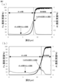
- FIG. 2 shows the results of GDS analysis of a plated steel sheet
- FIG. 2(a) shows the results of GDS analysis of an Al-containing plated steel sheet produced by a conventional method
- FIG. 4 shows GDS analysis results of plated steel sheets useful for use in welded joints according to embodiments.
- the Al concentration peak is relatively high, in the Al-containing plated steel sheet produced by the usual method, a larger amount of Al in the coating layer is consumed to form the Fe—Al barrier layer, resulting in a relatively high Al concentration peak. A thick Fe--Al barrier layer is formed. Therefore, in FIG. 2( a ), the Al concentration decreases greatly as it progresses from the vicinity of the interface between the base steel sheet and the coating layer to the coating surface side, and then becomes a substantially constant and very low value, and the Fe concentration decreases. It can be seen that the Al concentration shows a low value of about 0.1% at the plating layer center corresponding to the intermediate position between the plating layer position and the plating surface, which is 50% of .
- the Al phase present in the coating layer other than the Fe-Al barrier layer prevents molten Zn from penetrating into the steel sheet during spot welding. Considering that it plays a very important role in suppressing or reducing it, further investigation was carried out. As a result, the present inventors controlled the total amount of Al added to a relatively low amount of 1.50% by mass or less to suppress the deterioration of the LME resistance due to the decrease in the melting point of the plating layer.
- the ratio of "Al concentration at the center of the coating layer” / "Al concentration at the coating layer position where the Fe concentration is 50% of the base steel sheet” is controlled within the range of 0.10 to 1.50 by doing so, the inventors have found that the effect of adding Al to the plating layer can be sufficiently exhibited.
- the present inventors found that by using such a plated steel sheet, during spot welding, the separation portion in the heat-affected zone immediately outside the pressure contact portion, more specifically, 500 ⁇ m from the end of the pressure contact portion
- the structure of the initial plating layer changes in the separation part of the region, and a plating layer is formed in which the ratio of the area ratio of the ⁇ phase to the total area ratio of the ⁇ phase and the ⁇ phase is 10 to 100%.
- the present inventors have found that the corrosion resistance of the weld zone is significantly improved by increasing the ratio of the ⁇ phase, which is mainly composed of Zn, in the coating layer of the weld zone. I found that it can be done.
- Al in the initial plating layer acts as follows during spot welding. It is believed that this suppresses or reduces the intrusion of Zn, which has turned into a liquid phase due to the welding heat input, into the steel sheet along the grain boundaries.
- the Fe—Al barrier layer formed at the interface between the base steel sheet and the coating layer in the plated steel sheet is relatively fragile, the steel sheet may be damaged due to the pressure applied by the electrode during spot welding. It is considered that the material is relatively easily ruptured by the applied stress.
- the amount of Al in the entire plating layer is kept relatively low, while the amount of Al in the plating layer other than the Fe—Al barrier layer is increased.
- the plating structure of the plated steel sheet in the separation part of is changed to a structure with a relatively high proportion of ⁇ phase, and in relation to this, the penetration of molten Zn into the steel plate during spot welding can be suppressed or reduced.
- the corrosion resistance of the weld zone can also be improved has not been known in the past, and has been clarified for the first time by the inventors of the present invention.
- one or more of the plurality of superimposed steel plates correspond to the base material steel plate and, among the surfaces of the base material steel plate, at least the overlapping surfaces of the plurality of steel plates. It is a plated steel sheet provided with a plated layer formed on the surface.
- the plating layer of this plated steel sheet has the following chemical composition, which is the same as the initial chemical composition before spot welding, at the separation portion outside the heat affected zone.
- Al is an element that is effective in suppressing the intrusion of molten Zn into the steel sheet along the grain boundaries.
- the Al content is set to 0.10% or more.
- Al content is 0.12% or more, 0.15% or more, 0.18% or more, 0.20% or more, 0.25% or more, 0.30% or more, 0.35% or more, 0.40% 0.50% or more, 0.52% or more, 0.55% or more, 0.60% or more, 0.62% or more, 0.65% or more, or 0.70% or more.
- the Al content is set to 1.50% or less.
- Al content is 1.45% or less, 1.40% or less, 1.30% or less, 1.20% or less, 1.10% or less, 1.00% or less, 0.90% or less, or 0.80% It may be below.
- Fe for example, dissolves out of the base steel sheet into the plating bath, or reacts with Al during the plating process to form an Fe—Al barrier layer at the interface between the base steel sheet and the plating layer. It is an element that is unavoidably contained in the layer. Therefore, in the embodiment of the present invention, the Fe content in the plating layer is 0.01% or more. Fe content is 0.04% or more, 0.05% or more, 0.10% or more, 0.15% or more, 0.20% or more, 0.25% or more, 0.30% or more, 0.40% or more, or 0.50% or more.
- the Fe content in the plating layer is set to 2.00% or less.
- Fe content is 1.80% or less, 1.60% or less, 1.50% or less, 1.30% or less, 1.20% or less, 1.00% or less, 0.90% or less, 0.80% Below, it may be 0.70% or less or 0.60% or less.
- the basic chemical composition of the plating layer is as above. Furthermore, the plating layer is optionally Mg: 0 to 1.500%, Si: 0 to 1.000%, Ni: 0 to 1.000%, Ca: 0 to 4.000%, Sb: 0 to 0.500%, Pb: 0-0.500%, Cu: 0-1.000%, Sn: 0-1.000%, Ti: 0-1.000%, Cr: 0-1.000%, Nb: 0-1.000%, Zr: 0-1.000%, Mn: 0-1.000%, Mo: 0-1.000%, Ag: 0-1.000%, Li: 0-1 .000%, La: 0-0.500%, Ce: 0-0.500%, B: 0-0.500%, Y: 0-0.500%, P: 0-0.500%, and Sr: At least one of 0 to 0.500% may be contained.
- the total content of these optional elements is 5.000% or less from the viewpoint of sufficiently exhibiting the action and function of the above-mentioned basic components constituting the plating layer, especially Al.
- Optional elements totaling no more than 4.500%, no more than 4.000%, no more than 3.500%, no more than 3.000%, no more than 2.500%, no more than 2.000%, no more than 1.500% or 1 It may be 0.000% or less.
- Mg is an effective element for improving the corrosion resistance of the plating layer.
- the Mg content may be 0%, the Mg content is preferably 0.001% or more in order to obtain such effects.
- the Mg content may be 0.010% or more, 0.050% or more, or 0.100% or more.
- the Mg content is preferably 1.500% or less.
- the Mg content may be 1.200% or less, 1.000% or less, 0.800% or less, or 0.500% or less.
- Si is an effective element for improving the corrosion resistance of the plating layer.
- the Si content may be 0%, Si may be contained in the plating layer in an amount of 0.0001% or more or 0.001% or more, as required.
- excessive Si content may reduce the plating adhesion of the plating layer. Therefore, the Si content is preferably 1.000% or less.
- the Si content may be 0.800% or less, 0.500% or less, 0.100% or less, or 0.050% or less.
- Ni is an effective element for improving the corrosion resistance of the plating layer.
- the Ni content may be 0%, the Ni content is preferably 0.001% or more in order to obtain such effects.
- the Ni content may be 0.005% or more, 0.010% or more, or 0.020% or more.
- the Ni content is preferably 1.000% or less.
- the Ni content may be 0.800% or less, 0.600% or less, or 0.400% or less.
- Ca is an effective element for ensuring the wettability of the plating bath.
- the Ca content may be 0%, the Ca content is preferably 0.001% or more in order to obtain such effects.
- the Ca content may be 0.010% or more, 0.100% or more, or 1.000% or more.
- the Ca content is preferably 4.000% or less.
- the Ca content may be 3.000% or less, 2.000% or less, or 1.500% or less.
- the content of Sb, Pb, La, Ce, B, Y, P and Sr is preferably 0.500% or less, for example 0.300% or less, 0.100% or less or 0.050% or less may be Similarly, the content of Cu, Sn, Ti, Cr, Nb, Zr, Mn, Mo, Ag and Li is preferably 1.000% or less, for example 0.800% or less, 0.500% or less, or It may be 0.100% or less.
- the balance other than the above elements consists of Zn and impurities.
- Impurities in the plating layer are components and the like that are mixed due to various factors in the manufacturing process, including raw materials, when manufacturing the plating layer.
- the chemical composition of the plating layer is determined by dissolving the plating layer in an acid solution containing an inhibitor that suppresses the corrosion of the base steel sheet, and measuring the resulting solution by ICP (inductively coupled plasma) emission spectroscopy. be able to.
- the plating layer may be any plating layer having the chemical composition described above and is not particularly limited, but is preferably a hot-dip galvanized (GI) layer, for example.
- GI hot-dip galvanized
- the Fe content in the coating layer increases, and the final coating layer has the desired chemical composition and "Al concentration in the center of the coating layer" / "Fe concentration is the base material steel sheet In some cases, it may not be possible to obtain a ratio of "Al concentration at the plating layer position" that is 50% of.
- the thickness of the plating layer may be, for example, 3 to 50 ⁇ m.
- the coating weight of the plating layer is not particularly limited, but may be, for example, 10 to 170 g/m 2 per side.
- the adhesion amount of the plating layer is determined by dissolving the plating layer in an acid solution to which an inhibitor is added to suppress corrosion of the base steel sheet, and from the change in weight before and after pickling.
- the ratio of the area ratio of the ⁇ phase to the total area ratio of the ⁇ phase and the ⁇ phase is 10 to 100%. Since the region of 500 ⁇ m from the end of the press-contact portion corresponds to the region within the heat-affected zone, the heat input during spot welding generally facilitates the alloying of Zn in the coating layer in this region.
- the plating layer has a high proportion of the ⁇ phase and a relatively low proportion of the ⁇ phase, which is mainly composed of Zn (Zn concentration of 97 atomic % or more).
- the ⁇ phase A plating layer having a relatively high ratio of is formed, specifically, a plating layer having a ratio of the area ratio of the ⁇ phase to the total area ratio of the ⁇ phase and the ⁇ phase of 10% or more as described above.
- the fact that the proportion of ⁇ phase is relatively high suggests that Zn alloying does not proceed sufficiently even with the heat input of spot welding. It can be said that this suggests that direct contact is suppressed or reduced.
- the intrusion of molten Zn into the steel sheet during spot welding is suppressed or reduced, so that the LME resistance of the resulting welded joint can be improved. Therefore, from the viewpoint of improving the LME resistance of the welded joint and further the corrosion resistance of the weld zone, the higher the ratio of the ⁇ phase in the coating layer in the separation part immediately outside the pressure contact part, the better.
- the ratio of the area ratio of the ⁇ phase to the sum of the area ratios of the ⁇ phase and the ⁇ phase is preferably 15% or more, more preferably 25% or more, and most preferably 40% or more. % or more or 70% or more.
- the proportion of the ⁇ phase can be increased by increasing the Al content of the entire coating layer and applying a method for manufacturing a plated steel sheet, which will be described later in detail.
- the Al content of the entire plating layer should be 0.30% or more. is preferred.
- the upper limit can be appropriately set within a range of 100% or less.
- the ratio of the area ratio of the ⁇ phase to the sum of the area ratios of the ⁇ phase and the ⁇ phase may be 95% or less, 90% or less, 85% or less, or 80% or less.
- the structure of the plating layer in the separation portion immediately outside the pressure contact portion is mainly composed of the ⁇ phase and the ⁇ phase.
- the total area ratio of the ⁇ phase and the ⁇ phase may be 70% or more or 80% or more.
- the sum of the area ratios of ⁇ phase and ⁇ phase may be 100% or less, 95% or less, or 90% or less.
- the ratio of the ⁇ phase in the separation portion in the region of 500 ⁇ m from the end of the pressure contact portion is determined as follows. First, a cross-sectional sample of the spot welded portion is prepared, and then a backscattered electron image (BSE image) including the end of the pressure welded portion is obtained by a scanning electron microscope with an electron probe microanalyzer (SEM-EPMA). The end of the pressure contact portion of the welded portion and a region of 500 ⁇ m from the end of the pressure contact portion toward the separation portion (boundary portion between the pressure contact portion and the separation portion) are specified.
- BSE image backscattered electron image
- SEM-EPMA electron probe microanalyzer
- the ⁇ phase has a Zn concentration of 97 atomic % or more, an Fe concentration of 3 atomic % or less, and other impurities of 3 atomic % or less
- the ⁇ phase has a Zn concentration of 87 atomic % or more and an Fe concentration of A phase containing 8 to 13 atomic % and 3 atomic % or less of other impurities.
- the field of view of the SEM image is 100 ⁇ m ⁇ 100 ⁇ m, and the same elemental analysis is performed on five different points in the boundary, and the ratio of the area ratio of ⁇ phase to the total area ratio of ⁇ phase and ⁇ phase is obtained in each field of view. Finally, by averaging them, the ratio of the area ratio of the ⁇ phase to the sum of the area ratios of the ⁇ phase and the ⁇ phase is determined.
- the purpose of suppressing or reducing the occurrence of LME cracking during spot welding is to determine the chemical composition of the coating layer and the ratio of ⁇ phase in the coating layer in the separation portion immediately outside the pressure contact portion.
- the above GDS requirement is not an essential technical feature for achieving the object of the present invention, but is a preferred means for reliably controlling the ratio of the ⁇ phase in the plating layer of the separation portion within a desired range. It's just one of us.
- the ratio of "Al concentration at the center of the plating layer"/"Al concentration at the position of the plating layer where the Fe concentration is 50% of the base material steel sheet" is, for example, 0.15 or more, 0.20 or more, 0.20 or more. It may be 30 or more, 0.40 or more, or 0.50 or more.
- the ratio of "Al concentration at the center of the plating layer” / "Al concentration at the position of the plating layer where the Fe concentration is 50% of the base steel sheet” is 1.40 or less, 1.30 or less, 1.20 or less, It may be 1.10 or less or 1.00 or less.
- the Al concentration at a depth position where the Fe strength is 50% of the Fe strength of the base steel sheet (Fe strength at a depth of 100 ⁇ m from the surface of the plating layer of the sample) in GDS measurement is defined as "Fe concentration is The Al concentration at the coating layer position that is 50% of the base steel sheet", and the distance from this depth position to the surface is defined as the thickness of the coating layer.
- the Al concentration by GDS at the 1/2 position of the thickness of the plating layer is determined as the “Al concentration at the center of the plating layer”, and finally the “Al concentration at the center of the plating layer” / “Fe concentration is 50 of the base steel sheet.
- the ratio of the Al concentration at the plating layer position is determined.
- the base material steel sheet for forming the plating layer is not particularly limited and may be any suitable material, particularly cold-rolled steel sheet.
- the base steel sheet may be a material having a chemical composition such that the plated steel sheet has a tensile strength of 780 MPa or more.
- LME cracking becomes conspicuous when steel sheets having relatively high strength are spot-welded, and that the higher the strength of the steel sheet, the higher the susceptibility to LME cracking. Therefore, when a plated steel sheet having a high tensile strength of 780 MPa or more is used in welded joints, the effect of suppressing LME cracking is particularly remarkable.
- an object of the present invention is to provide a welded joint capable of suppressing or reducing the occurrence of LME cracking during spot welding, wherein at least one of a plurality of superimposed steel plates is a plated steel sheet having a plating layer on at least the surface corresponding to the overlapping surface, and the plating layer is controlled to have a predetermined chemical composition in the separation part outside the heat affected zone, and a distance of 500 ⁇ m from the end of the pressure contact part
- the object is achieved by controlling the ratio of the ⁇ phase area ratio of the plating layer in the separation part of the region within the range of 10 to 100% with respect to the total area ratio of the ⁇ phase and the ⁇ phase. be.
- the base material steel plate is mass %, C: 0.01 to 0.50%, Si: 0.01 to 3.50%, Mn: 0.10-5.00%, P: 0.100% or less, S: 0.0300% or less, N: 0.0100% or less, O: 0 to 0.020%, Al: 0 to 1.000%, B: 0 to 0.010%, Nb: 0 to 0.150%, Ti: 0 to 0.20%, Mo: 0-3.00%, Cr: 0 to 2.00%, V: 0 to 1.00%, Ni: 0 to 2.00%, W: 0 to 1.00%, Ta: 0 to 0.10%, Co: 0 to 3.00%, Sn: 0 to 1.00%, Sb: 0 to 0.50%, Cu: 0 to 2.00%, As: 0 to 0.050%, Mg: 0-0.100%, Ca: 0-0.100%, Zr: 0 to 0.100%, Hf: 0 to 0.100%, It
- C is an element that increases the tensile strength at low cost and is an important element for controlling the strength of steel.
- the C content is preferably 0.01% or more.
- C content may be 0.05% or more, 0.08% or more, 0.09% or more, 0.10% or more, 0.11% or more, 0.12% or more, or 0.15% or more .
- an excessive C content may lead to a decrease in elongation. Therefore, the C content is preferably 0.50% or less.
- the C content may be 0.40% or less, 0.35% or less, or 0.30% or less.
- Si is an element that acts as a deoxidizing agent and suppresses the precipitation of carbides during the cooling process during cold-rolled sheet annealing.
- the Si content is preferably 0.01% or more.
- the Si content may be 0.10% or more, 0.12% or more, 0.15% or more, 0.30% or more, or 0.80% or more.
- an excessive Si content may increase the strength of the steel and decrease the elongation. Therefore, the Si content is preferably 3.50% or less.
- the Si content may be 2.50% or less, 2.00% or less, or 1.50% or less.
- Mn is an element that affects the ferrite transformation of steel and is an element that is effective in increasing strength. In order to sufficiently obtain such effects, the Mn content is preferably 0.10% or more. The Mn content may be 0.50% or more, 1.00% or more, or 1.50% or more. On the other hand, an excessive Mn content may increase the strength of the steel and decrease the elongation. Therefore, the Mn content is preferably 5.00% or less. The Mn content may be 4.00% or less, 3.00% or less, or 2.50% or less.
- P is an element that segregates at grain boundaries and promotes embrittlement of steel. Since the P content is preferably as small as possible, it is ideally 0%. However, an excessive reduction in P content may lead to a significant increase in cost. Therefore, the P content may be 0.0001% or more, 0.001% or more, or 0.005% or more. On the other hand, an excessive P content may cause embrittlement of the steel due to grain boundary segregation as described above. Therefore, the P content is preferably 0.100% or less. The P content may be 0.050% or less, 0.030% or less, or 0.010% or less.
- S is an element that forms non-metallic inclusions such as MnS in steel and causes a decrease in ductility of steel parts.
- the S content is 0% because the smaller the S content, the better.
- the S content may be 0.0001% or more, 0.0002% or more, 0.0010% or more, or 0.0050% or more.
- an excessive S content may cause cracks starting from non-metallic inclusions during cold forming. Therefore, the S content is preferably 0.0300% or less.
- the S content may be 0.0200% or less, 0.0150% or less, or 0.0100% or less.
- N is an element that forms coarse nitrides in the steel sheet and reduces the workability of the steel sheet.
- the N content is 0% because the smaller the N content, the better.
- the N content may be 0.0001% or more, 0.0005% or more, or 0.0010% or more.
- the N content is preferably 0.0100% or less.
- the N content may be 0.0080% or less or 0.0050% or less.
- the preferred basic chemical composition of the base steel sheet is as described above. Furthermore, the base material steel plate, if necessary, replaces part of the remaining Fe with O: 0 to 0.020%, Al: 0 to 1.000%, B: 0 to 0.010%, Nb : 0-0.150%, Ti: 0-0.20%, Mo: 0-3.00%, Cr: 0-2.00%, V: 0-1.00%, Ni: 0-2.
- the balance other than the above elements consists of Fe and impurities.
- Impurities in the base steel sheet are components that are mixed due to various factors in the manufacturing process, including raw materials such as ores and scraps, when the base steel sheet is industrially manufactured.
- the chemical composition of the base steel sheet can be measured by a general analytical method.
- the chemical composition of the base steel sheet may be measured by first removing the plating layer by mechanical grinding and then using Inductively Coupled Plasma-Atomic Emission Spectrometry (ICP-AES).
- C and S can be measured using a combustion-infrared absorption method
- N can be measured using an inert gas fusion-thermal conductivity method
- O can be measured using an inert gas fusion-nondispersive infrared absorption method.
- the plate thickness of the base steel plate is not particularly limited, but is, for example, 0.2 mm or more, and may be 0.3 mm or more, 0.6 mm or more, 1.0 mm or more, or 2.0 mm or more.
- the plate thickness of the base steel plate is, for example, 6.0 mm or less, and may be 5.0 mm or less or 4.0 mm or less.
- Galvanized steel sheets useful for use in welded joints according to embodiments of the present invention may have any suitable tensile strength, and preferably have a tensile strength of, for example, 780 MPa or greater, but are not particularly limited. .
- LME cracking becomes conspicuous when steel sheets having relatively high strength are spot-welded. Therefore, when the plated steel sheet has a high tensile strength of 780 MPa or more, the effect of suppressing LME cracking is particularly remarkable as compared with conventional plated steel sheets having the same tensile strength.
- the plated steel sheet may have a tensile strength of 980 MPa or higher, 1080 MPa or higher, or 1180 MPa or higher.
- the upper limit is not particularly limited, for example, the tensile strength of the plated steel sheet may be 2300 MPa or less, 2000 MPa or less, 1800 MPa or less, or 1500 MPa or less.
- Tensile strength is measured by taking a JIS No. 5 test piece from a direction in which the longitudinal direction of the test piece is parallel to the rolling direction of the plated steel sheet, and performing a tensile test in accordance with JIS Z 2241:2011.
- the plated steel sheet useful for use in the welded joint according to the embodiment of the present invention more specifically, when measured by glow discharge optical emission spectroscopy (GDS), the "Al concentration at the center of the plating layer"
- GDS glow discharge optical emission spectroscopy
- a preferred method for producing a plated steel sheet provided with a plating layer having a ratio of 0.10 to 1.50 of /"Al concentration at the position of the plating layer where the Fe concentration is 50% of the base steel sheet" will be described.
- the following description is intended to exemplify a characteristic method for manufacturing the plated steel sheet, and is intended to limit the plated steel sheet to those manufactured by the manufacturing method described below. not something to do.
- a plated steel sheet is produced by, for example, a casting process in which molten steel with an adjusted chemical composition is cast to form a billet, a hot rolling process in which the steel billet is hot rolled to obtain a hot rolled steel sheet, and a coiling process in which the hot rolled steel sheet is coiled. , a cold-rolling step of cold-rolling the coiled hot-rolled steel sheet to obtain a cold-rolled steel sheet, a pretreatment step, an annealing step of annealing the pre-treated cold-rolled steel sheet, and forming a coating layer on the obtained base steel sheet. It can be manufactured by performing a plating process to do. Alternatively, the cold rolling process may be performed as it is after pickling without winding after the hot rolling process. Each step will be described in detail below.
- Conditions for the casting process are not particularly limited. For example, following smelting using a blast furnace, an electric furnace, etc., various secondary smelting may be performed, and then casting may be performed by a method such as ordinary continuous casting or casting by an ingot method.
- a hot-rolled steel sheet can be obtained by hot-rolling the cast steel slab.
- the hot-rolling process is performed by hot-rolling a cast steel slab directly or by reheating it after cooling it once.
- the heating temperature of the billet may be, for example, 1100-1250.degree.
- rough rolling and finish rolling are usually performed.
- the temperature and rolling reduction for each rolling can be appropriately determined according to the desired metal structure and plate thickness.
- the finishing temperature of finish rolling may be 900 to 1050° C., and the rolling reduction of finish rolling may be 10 to 50%.
- a hot-rolled steel sheet can be coiled at a predetermined temperature.
- the coiling temperature can be appropriately determined depending on the desired metal structure and the like, and may be, for example, 500 to 800.degree.
- the hot-rolled steel sheet may be subjected to a predetermined heat treatment by unwinding before or after winding. Alternatively, the coiling process may not be performed, and after the hot rolling process, pickling may be performed and the cold rolling process described below may be performed.
- the hot-rolled steel sheet After subjecting the hot-rolled steel sheet to pickling or the like, the hot-rolled steel sheet can be cold-rolled to obtain a cold-rolled steel sheet.
- the rolling reduction of cold rolling can be appropriately determined according to the desired metal structure and plate thickness, and may be, for example, 20 to 80%.
- air cooling may be performed to cool to room temperature.
- Pretreatment process it is effective to perform a predetermined pretreatment process before annealing the cold-rolled steel sheet.
- pretreatment steps may include degreasing and optional grinding.
- the degreasing treatment may include, for example, electrifying the cold-rolled steel sheet in a solution of pH 8.0 or higher (electrolytic treatment).
- the current density during energization may be 1.0 to 8.0 A/dm 2 and the energization time may be 5 to 10 seconds.
- the optional grinding process is preferably carried out with heavy grinding brushes.
- the nucleation of the Fe-Al barrier layer is promoted during the plating process after the annealing process, and the Fe-Al barrier layer is densified. and the associated slow growth rate of the Fe—Al barrier layer, which allows its thickness to be reduced.
- the amount of Al consumed for forming the Fe--Al barrier layer can be reduced. Therefore, since the amount of Al in the plating layers other than the Fe—Al barrier layer can be increased, the finally obtained plated steel sheet has the ratio of "Al concentration at the center of the plating layer"/"Fe concentration of 50% of the base material steel sheet".
- the ratio of "Al concentration at the plating layer position" can be increased.
- the grinding treatment is not particularly limited, but can be performed, for example, by grinding the surface of the cold-rolled steel sheet with a heavy grinding brush under conditions of a grinding amount of 10 to 200 g/m 2 .
- the amount of grinding by the heavy grinding brush can be adjusted by any appropriate method known to those skilled in the art, and is not particularly limited. can be adjusted by appropriately selecting
- Annealing is performed on the cold-rolled steel sheet that has undergone the pretreatment process.
- the holding temperature in the annealing step is preferably 700-900°C. If the holding temperature in the annealing step is higher than 900°C, an external oxide layer may form on the surface of the steel sheet, degrading the plateability.
- the rate of temperature increase to the holding temperature is not particularly limited, but may be 1 to 10° C./sec.
- the retention time at the above retention temperature is preferably 10 to 300 seconds, more preferably 80 to 120 seconds. If the holding time is longer than 300 seconds, the external oxide may grow excessively and the plating properties may deteriorate.
- the dew point of the atmosphere in the annealing step is preferably -20 to 10°C, more preferably -10 to 5°C. If the dew point is too low, an external oxide layer may be formed on the surface of the steel sheet, degrading the platability. On the other hand, if the dew point is too high, Fe oxide may be similarly generated as an external oxide on the surface of the steel sheet, resulting in deterioration of the plateability.
- the atmosphere in the annealing step may be a reducing atmosphere, more specifically a reducing atmosphere containing nitrogen and hydrogen, such as a reducing atmosphere containing 1-10% hydrogen (eg, 4% hydrogen and nitrogen balance).
- a plating layer having the chemical composition and structure described above is formed on at least one, preferably both surfaces of the cold-rolled steel sheet (base material steel sheet). More specifically, the plating step is performed by hot-dip plating using a plating bath whose composition is adjusted so that the chemical composition of the plating layer is within the range described above.
- the time from immersing the steel sheet in the plating bath to the start of cooling is controlled to 6 seconds or less, and then the average cooling rate from the bath temperature (eg, 420 to 480 ° C.) to 370 ° C. is 20 ° C. /sec or more is extremely important.
- the Fe—Al barrier layer can be made thinner and the amount of Al consumed to form the Fe—Al barrier layer can be reduced. It becomes possible to sufficiently secure the amount of Al present in the.
- the ratio of "Al concentration at the center of the plating layer" / "Al concentration at the position of the plating layer where the Fe concentration is 50% of the base steel sheet” is set to 0.10 or more. be able to.
- the time from the start of immersion of the steel sheet in the plating bath to the start of cooling exceeds 6 seconds and/or the average cooling rate from the bath temperature to 370 ° C.
- the time from the start of immersion of the steel sheet in the plating bath to the start of cooling be shorter and the average cooling rate from the bath temperature to 370° C. be faster.
- the Al content of the entire plating layer is 0.30% or more
- the time from the start of immersion of the steel sheet in the plating bath to the start of cooling is 4 seconds or less
- the average cooling rate from the bath temperature to 370 ° C. is 40. C./sec or higher can further improve the LME resistance of the welded joint.
- the time from the start of immersion of the steel sheet in the plating bath to the start of cooling is 6 seconds or less, and the average cooling rate from the bath temperature to 370 ° C.
- the Al content of the entire plating layer is set to 0.30% or more, grinding treatment is performed with a heavy grinding brush as the pretreatment step described above, and cooling is started from the start of immersion of the steel sheet in the plating bath.
- the lower limit of the time from the start of immersion of the steel sheet in the plating bath to the start of cooling is not particularly limited, but for example, the time from the start of immersion of the steel sheet in the plating bath to the start of cooling may be 2 seconds or more.
- the upper limit of the average cooling rate from the bath temperature to 370°C is not particularly limited, but for example, the average cooling rate from the bath temperature to 370°C may be 80°C/sec or less.
- Other conditions of the plating process may be appropriately set in consideration of the thickness and adhesion amount of the plating layer.
- the coating amount of the coating layer is within a predetermined range, such as , can be adjusted within the range of 10 to 170 g/m 2 per side.
- the ratio of "Al concentration at the center of the plating layer” / "Al concentration at the position of the plating layer where the Fe concentration is 50% of the base steel sheet” is 0.10 to 1.50. Since it is controlled within the range, when used in spot welding, the structure of the initial plating layer changes in the separation part in the region of 500 ⁇ m from the end of the pressure contact part, and the total area ratio of ⁇ phase and ⁇ phase A coating layer having an area ratio of ⁇ phase of 10 to 100% is formed, and in relation to this, it is possible to remarkably suppress or reduce penetration of molten Zn into the steel sheet during spot welding.
- any appropriate steel sheet or plated steel sheet can be used as the steel sheet other than the plated steel sheet described above among the plurality of steel sheets used in the welded joint according to the embodiment of the present invention.
- Such a steel sheet may have, for example, a tensile strength of 780 MPa or more like the preferred embodiment of the plated steel sheet, or may have a tensile strength of less than 780 MPa. Therefore, as for steel sheets other than the plated steel sheets described above, an appropriate steel sheet or plated steel sheet may be appropriately selected according to the use of the welded joint and desired properties, such as desired joint strength.
- the welded joint according to the embodiment of the present invention uses the above-described plated steel sheet in all steel sheets, and uses the above-described plated steel sheet in a plurality of steel sheets that are superimposed or one or more steel sheets, and the plated steel sheet is used. It can be manufactured by applying any suitable spot welding method known to those skilled in the art to a plurality of steel sheets stacked with other steel sheets or other plated steel sheets. For example, a plurality of steel plates stacked as described above are pressurized using a pair of electrodes facing each other, and an electric current is passed between the electrodes under normal conditions to form a nugget and a press-contact portion around it.
- the spot welding conditions may be any suitable conditions known to those skilled in the art.
- the welding electrode may be a dome radius type welding electrode with a tip diameter of 6 to 8 mm, a pressure of 1.5 to 6.0 kN, an energization time of 0.1 to 1.0 s (5 to 50 cycles, power supply frequency of 50 Hz), an applied current of 4 to 15 kA, and a striking angle (the angle between the axial direction of the electrode and the direction perpendicular to the surface of the steel sheet) of 0 to 10°.
- the effect of adding Al to the coating layer is fully exhibited, and the ratio of the ⁇ phase in the coating layer in the separation portion immediately outside the pressure contact portion is adjusted to the desired value. It can be controlled within the range, and in relation to this, it becomes possible to suppress or reduce the intrusion of molten Zn into the inside of the steel sheet during spot welding. Therefore, such a welded joint is more advantageous than using a conventional plated steel sheet with a coating layer having a similar chemical composition, more specifically a Zn-based coating layer having a similar Al content. This makes it possible to achieve better LME resistance, and contributes to the development of industry through improved crash safety and longer life, particularly in the automotive field.
- the obtained cold-rolled steel sheet is subjected to a pretreatment in which a current density of 5.0 A/dm 2 is applied for 8 seconds in a pH 9.2 solution.
- a heavy grinding brush (D-100 manufactured by Hotani Co., Ltd.) was used to grind the cold-rolled steel sheet with a grinding amount of 10 to 200 g / m 2 , a brush reduction of 2.0 mm, and a rotation speed of 600 rpm.
- the surface was ground to introduce strain into the surface of the cold-rolled steel sheet.
- Table 1 shows whether or not each cold-rolled steel sheet was ground with a heavy grinding brush.
- each cold-rolled steel sheet was cut into a size of 100 mm ⁇ 200 mm, and then subjected to annealing treatment (annealing atmosphere: hydrogen 4% and nitrogen balance) under the conditions of a dew point of 0 ° C., a holding temperature of 870 ° C., and a holding time of 100 seconds. rice field. All the steel plate samples were annealed at a heating rate of 5° C./sec.
- the cut steel plate sample was treated with a hot dip galvanizing bath having a predetermined bath composition, and the bath temperature shown in Table 1, the time from immersion in the plating bath to the start of cooling, and the average cooling rate from the bath temperature to 370 ° C.
- a plated steel plate sample having a plated layer formed on both surfaces of the steel plate sample was obtained. After immersion in the plating bath, the steel plate sample was pulled up and adjusted to 50 g/m 2 per side by N 2 gas wiping before starting cooling. In Comparative Example 28, an alloying heat treatment was performed at 520° C. for 10 seconds after the hot-dip galvanizing treatment.
- a plated steel sheet sample was cut into a size of 50 mm ⁇ 50 mm, and then the GDS measurement was performed on the cut plated steel sheet sample to obtain an Al concentration distribution from the surface of the coating layer to a depth of 100 ⁇ m.
- the Al concentration at a depth position where the Fe strength is 50% of the Fe strength of the base steel sheet (Fe strength at a depth of 100 ⁇ m from the surface of the plating layer of the sample) in GDS measurement is defined as "Fe concentration is Al concentration at the coating layer position which is 50% of the base material steel plate", and the distance from this depth position to the surface was defined as the thickness of the coating layer.
- the Al concentration by GDS at the 1/2 position of the thickness of the plating layer is determined as the “Al concentration at the center of the plating layer”, and finally the “Al concentration at the center of the plating layer” / “Fe concentration is 50 of the base steel sheet. %, the ratio of the Al concentration at the plating layer position was determined. As a result, in the plated steel sheet samples of all examples (invention examples), the ratio of "Al concentration at the center of the plating layer"/"Al concentration at the position of the plating layer where the Fe concentration is 50% of the base material steel sheet" was 0. It was controlled within the range of 10 to 1.50.
- a plated steel plate sample with a size of 100 ⁇ 100 mm was subjected to spot welding.
- Two sheets of 50 mm ⁇ 100 mm were cut to a size of 50 mm ⁇ 100 mm, and a dome radius welding electrode with a tip diameter of 8 mm was used for these two plated steel sheets, with a striking angle of 5 ° and a pressure of 4.0 kN.
- the chemical composition of the plating layer was determined by immersing a 30 mm ⁇ 30 mm sample taken from the separation part outside the heat-affected zone of the welded joint in a 10% HCl aqueous solution containing an inhibitor (IBIT manufactured by Asahi Chemical Industry Co., Ltd.) and pickling the plating layer. After stripping, the plating components dissolved in the aqueous solution were determined by measuring by ICP emission spectroscopy. Table 1 shows the results.
- the ratio of the ⁇ phase in the separation portion in the region of 500 ⁇ m from the end of the pressure contact portion was determined as follows. First, a cross-sectional sample of the spot welded portion is prepared, and then a BSE image including the end of the pressure contact portion is obtained by SEM-EPMA. A 500 ⁇ m region (boundary portion between the pressure contact portion and the separation portion) was specified from the . Next, an elemental analysis was performed on the identified boundary to identify the area ratio of the ⁇ phase and the area ratio of the ⁇ phase at the boundary.
- the ⁇ phase has a Zn concentration of 97 atomic % or more, an Fe concentration of 3 atomic % or less, and other impurities of 3 atomic % or less, and the ⁇ phase has a Zn concentration of 87 atomic % or more and an Fe concentration of A phase containing 8 to 13 atomic % and 3 atomic % or less of other impurities was used.
- the field of view of the SEM image was 100 ⁇ m ⁇ 100 ⁇ m, and the same elemental analysis was performed on five different points in the boundary, and the ratio of the area ratio of the ⁇ phase to the total area ratio of the ⁇ phase and the ⁇ phase was obtained in each field of view. .
- the ratio of the area ratio of the ⁇ phase to the sum of the area ratios of the ⁇ phase and the ⁇ phase was determined.
- the total area ratio of the ⁇ phase and the ⁇ phase in the separation portion in the region of 500 ⁇ m from the end of the pressure contact portion was 80% or more.
- Comparative Example 26 since the Al content of the entire plating layer was low, the effect of suppressing LME cracking due to the addition of Al could not be sufficiently exhibited, and the LME resistance decreased.
- Comparative Example 27 it is considered that the melting point of the plating layer was lowered because the Al content of the entire plating layer was high. As a result, Zn in the coating layer was likely to melt during spot welding, and the LME resistance decreased.
- Comparative Example 28 the Fe content in the coating layer increased due to the alloying heat treatment, and the desired chemical composition of the coating could not be obtained.
- the ratio of "Al concentration at the plating layer position" was also less than 0.10.
- the ratio of "Al concentration at the center of the plating layer” / "Al concentration at the position of the plating layer where the Fe concentration is 50% of the base steel sheet" is less than 0.10, which is the same as in Comparative Examples 28 and 29. For this reason, the ratio of the area ratio of the ⁇ phase in the plating layer immediately outside the pressure contact portion decreased, and the LME resistance decreased.
- the welded joints according to all the examples have a predetermined plating chemical composition, and the area ratio of the ⁇ phase in the plating layer immediately outside the pressure contact part is controlled within the range of 10 to 100%.
- the effect of adding Al to the coating layer can be fully exhibited and LME cracking can be reliably suppressed or reduced.
- Corrosion resistance was also improved.
- Example 16 no grinding with a heavy grinding brush in which the time from to the start of cooling was 4 seconds and the average cooling rate from the bath temperature to 370 ° C. was 40 ° C./sec, the ⁇ phase in the plating layer immediately outside the pressure contact part area ratio became 25% or more, and as a result, the evaluation of LME resistance and weld zone corrosion resistance also became AA, and the LME resistance and weld zone corrosion resistance were further improved.
- the Al content of the entire plating layer is set to 0.30% or more, grinding with a heavy grinding brush is performed as a pretreatment for the annealing process, and the time from the start of immersion of the steel sheet in the plating bath to the start of cooling. 4 seconds and the average cooling rate from the bath temperature to 370° C. was 40° C./second. 40% or more, and as a result, the evaluation of LME resistance and weld zone corrosion resistance also became AAA, and the LME resistance and weld zone corrosion resistance were further improved.
Abstract
Provided is a welded joint comprising stacked multiple steel plates, a spot-welded section having a nugget for joining the multiple steel plates together as well as a press-contact portion and a heat-affected zone which are formed around the nugget, and a separation section positioned around the press-contact portion, said welded joint being characterized in that: at least one of the multiple steel plates is a plated steel plate which comprises a base steel plate and a plating layer formed on one of the surfaces of the base steel plate that corresponds at least to an overlapping surface for the multiple steel plates; a plating layer portion in the separation section disposed outside the heat-affected zone has a predetermined chemical composition; and in the plating layer portion in a 500 µm region of the separation section from an end part of the press-contact portion, the ratio of the area ratio of η-phase to the total area ratio of η-phase and Γ-phase is 10 to 100%.
Description
本発明は、溶接継手に関し、より詳しくはめっき鋼板をスポット溶接して得られる溶接継手に関する。
The present invention relates to a welded joint, and more particularly to a welded joint obtained by spot welding plated steel sheets.
自動車等で用いられる鋼板は良好な溶接施工性が求められる。自動車車体の組立及び部品の取付けなどの工程では、主としてスポット溶接が利用されているが、特に亜鉛めっき鋼板同士のスポット溶接又は亜鉛めっき鋼板と非めっき鋼板のスポット溶接においては、液体金属脆化(Liquid Metal Embrittle:LME)割れを抑制する必要がある。この現象は、溶接入熱により液相化した亜鉛が結晶粒界に沿って鋼板内部に侵入して脆化したところに、溶接により発生する引張応力が作用することで生じる割れである。スポット溶接において、このようなLME割れが生じると、溶接継手の強度が確保できなくなるため、亜鉛めっき鋼板の使用が阻害される場合がある。
Good weldability is required for steel plates used in automobiles and the like. Spot welding is mainly used in processes such as assembly of automobile bodies and attachment of parts. In particular, spot welding of galvanized steel sheets or spot welding of galvanized steel sheets and non-galvanized steel sheets is susceptible to liquid metal embrittlement ( Liquid Metal Embrittle: LME) It is necessary to suppress cracking. This phenomenon is cracking that occurs when tensile stress generated by welding acts on the embrittled part of the steel sheet where zinc, which has been liquefied by welding heat input, penetrates along the grain boundaries into the steel sheet. If such LME cracking occurs in spot welding, the strength of the welded joint cannot be ensured, which may hinder the use of the galvanized steel sheet.
これに関連して、特許文献1では、スポット溶接方法を改良することでこのようなLME割れに対処することが教示されている。より具体的には、特許文献1では、溶接電極間の通電終了後に溶接電極の加圧保持を継続(溶接後保持時間Htを延長)し、当該溶接後保持時間Htを被溶接部材の総板厚tの関数として調整することで、電極開放前に溶融した亜鉛系めっきを凝固させ、その結果として溶融した亜鉛系めっきが溶接残留応力の高い箇所の鋼板の結晶粒界に侵入せず、割れを抑制できることが教示されている。
In this regard, Patent Document 1 teaches addressing such LME cracking by improving the spot welding method. More specifically, in Patent Literature 1, after the energization between the welding electrodes is completed, the welding electrodes are kept under pressure (extending the post-welding holding time Ht), and the post-welding holding time Ht is Adjusting the thickness as a function of t allows the molten zinc-based coating to solidify before the electrode is opened, so that the molten zinc-based coating does not enter the grain boundaries of the steel sheet at locations where welding residual stress is high, preventing cracking. can be suppressed.
特許文献2では、スポット溶接後のスポット溶接部近傍のめっき組織を制御することで割れを抑止することが教示されている。より具体的には、特許文献2では、複数枚の鋼板を重ね合わせた板組を、一対の電極によって挟持しスポット溶接して形成したスポット溶接部を有するスポット溶接部材であって、前記複数枚の鋼板のうち少なくとも1枚は、引張強度780MPa以上の高強度亜鉛系めっき鋼板であり、且つ、該高強度亜鉛系めっき鋼板のめっき中のAl含有量は0.5質量%以上であり、前記スポット溶接部のコロナボンド端部の外側の熱衝撃領域は、前記高強度亜鉛系めっき鋼板の母材鋼板と前記めっきとの界面に、平均厚さが0.3μm以上のFeAl合金層と、該FeAl合金層の上に平均厚さが2.0μm以上の亜鉛系めっき層を形成しためっき層を有するスポット溶接部材が記載されている。また、特許文献2では、母材鋼板へのZn侵入を抑制するためには、めっき中のAl含有量を0.5質量%以上とすることで、溶接時の入熱によって鋼板と該鋼板のめっきとの界面に高融点のFeAl合金層を形成することが重要であると教示されている。
Patent Document 2 teaches that cracks are suppressed by controlling the plating structure in the vicinity of spot welds after spot welding. More specifically, in Patent Document 2, a spot-welded member having a spot-welded portion formed by sandwiching and spot-welding a plate set in which a plurality of steel sheets are superimposed by a pair of electrodes, wherein the plurality of sheets At least one of the steel sheets is a high-strength zinc-based plated steel sheet having a tensile strength of 780 MPa or more, and the Al content in the coating of the high-strength zinc-based plated steel sheet is 0.5% by mass or more, The thermal shock region outside the corona bond end of the spot welded portion includes an FeAl alloy layer having an average thickness of 0.3 μm or more at the interface between the base steel plate of the high-strength zinc-based plated steel plate and the plating A spot-welded member having a plating layer in which a zinc-based plating layer having an average thickness of 2.0 μm or more is formed on an FeAl alloy layer is described. In addition, in Patent Document 2, in order to suppress the penetration of Zn into the base steel sheet, the Al content in the coating is set to 0.5% by mass or more, so that the heat input during welding causes the separation of the steel sheet and the steel sheet. It is taught that it is important to form a high melting point FeAl alloy layer at the interface with the plating.
特許文献1及び2では、スポット溶接方法を改良したり、スポット溶接後のスポット溶接部近傍のめっき組織を制御したりといった観点から、溶接継手におけるLME割れの抑制について検討がされている。しかしながら、特許文献1及び2では、スポット溶接前のめっき鋼板におけるめっき組織との関連で溶接継手におけるLME割れの発生を抑制することについては必ずしも十分な検討はなされていない。したがって、これらの特許文献に記載の発明では、耐LME性の向上に関して依然として改善の余地があった。
In Patent Documents 1 and 2, the suppression of LME cracking in welded joints is studied from the viewpoint of improving the spot welding method and controlling the plating structure in the vicinity of the spot welded portion after spot welding. However, Patent Literatures 1 and 2 do not necessarily conduct sufficient studies on suppressing the occurrence of LME cracks in welded joints in relation to the plating structure of the plated steel sheet before spot welding. Therefore, in the inventions described in these patent documents, there is still room for improvement regarding the improvement of LME resistance.
そこで、本発明は、新規な構成により、スポット溶接時のLME割れの発生を抑制又は低減することができる溶接継手を提供することを目的とする。
Therefore, an object of the present invention is to provide a welded joint capable of suppressing or reducing the occurrence of LME cracking during spot welding with a novel configuration.
本発明者らは、スポット溶接により溶接継手を製造する際のLME割れの発生を抑制又は低減するために、特に溶接継手に使用されるめっき鋼板におけるめっき層の組織に着目して検討を行った。その結果、本発明者らは、Alを比較的少ない量で含有しつつ、Al濃度分布を適切に制御しためっき層を備えためっき鋼板を使用することで、スポット溶接の際にLME割れが発生しやすい部分のめっき層組織を改善することができ、これに関連して溶接継手の耐LME性を顕著に改善することができることを見出し、本発明を完成させた。
In order to suppress or reduce the occurrence of LME cracks when producing welded joints by spot welding, the present inventors focused particularly on the structure of the plating layer in the plated steel sheet used for welded joints. . As a result, the present inventors found that LME cracking occurs during spot welding by using a plated steel sheet having a coating layer in which the Al concentration distribution is appropriately controlled while containing a relatively small amount of Al. The inventors have found that it is possible to improve the structure of the plating layer in the part that is susceptible to corrosion, and in relation to this, it is possible to significantly improve the LME resistance of the welded joint, and have completed the present invention.
上記目的を達成し得た本発明は下記のとおりである。
(1)重ね合わされた複数の鋼板と、
前記複数の鋼板を接合するナゲット、並びに、前記ナゲットの周囲に形成された圧接部及び熱影響部を有するスポット溶接部と、
前記圧接部の周囲に位置するセパレーション部と
を備える溶接継手であって、
前記複数の鋼板のうち1枚以上が、母材鋼板と、前記母材鋼板の表面のうち、少なくとも前記複数の鋼板の重ね面に相当する表面に形成されためっき層とを備えるめっき鋼板であり、
前記熱影響部の外側の前記セパレーション部における前記めっき層が、質量%で、
Al:0.10~1.50%、及び
Fe:0.01~2.00%
を含有し、さらに、
Mg:0~1.500%、
Si:0~1.000%、
Ni:0~1.000%、
Ca:0~4.000%、
Sb:0~0.500%、
Pb:0~0.500%、
Cu:0~1.000%、
Sn:0~1.000%、
Ti:0~1.000%、
Cr:0~1.000%、
Nb:0~1.000%、
Zr:0~1.000%、
Mn:0~1.000%、
Mo:0~1.000%、
Ag:0~1.000%、
Li:0~1.000%、
La:0~0.500%、
Ce:0~0.500%、
B :0~0.500%、
Y :0~0.500%、
P :0~0.500%、及び
Sr:0~0.500%
の少なくとも1種を合計で5.000%以下含有し、
残部がZn及び不純物からなる化学組成を有し、
前記圧接部の端部から500μmの領域の前記セパレーション部の前記めっき層において、η相及びΓ相の面積率の合計に対するη相の面積率の割合が10~100%であることを特徴とする、溶接継手。
(2)前記化学組成が、質量%で、Al:0.30~1.50%を含有し、前記圧接部の端部から500μmの領域の前記セパレーション部の前記めっき層において、η相及びΓ相の面積率の合計に対するη相の面積率の割合が25~100%であることを特徴とする、上記(1)に記載の溶接継手。
(3)前記化学組成が、質量%で、Al:0.30~1.50%を含有し、前記圧接部の端部から500μmの領域の前記セパレーション部の前記めっき層において、η相及びΓ相の面積率の合計に対するη相の面積率の割合が40~100%であることを特徴とする、上記(1)に記載の溶接継手。
(4)前記めっき層が溶融亜鉛めっき(GI)層であることを特徴とする、上記(1)~(3)のいずれか1項に記載の溶接継手。
(5)前記めっき鋼板が780MPa以上の引張強さを有することを特徴とする、上記(1)~(4)のいずれか1項に記載の溶接継手。 The present invention that has achieved the above object is as follows.
(1) a plurality of superimposed steel plates;
A spot weld having a nugget for joining the plurality of steel plates, and a pressure weld zone and a heat affected zone formed around the nugget;
A welded joint comprising a separation portion positioned around the pressure contact portion,
At least one of the plurality of steel plates is a plated steel plate comprising a base steel plate and a plated layer formed on a surface of the base steel plate that corresponds to at least the overlapping surface of the plurality of steel plates. ,
The plating layer in the separation portion outside the heat affected zone is, by mass%,
Al: 0.10-1.50% and Fe: 0.01-2.00%
and further
Mg: 0-1.500%,
Si: 0 to 1.000%,
Ni: 0 to 1.000%,
Ca: 0 to 4.000%,
Sb: 0 to 0.500%,
Pb: 0 to 0.500%,
Cu: 0 to 1.000%,
Sn: 0 to 1.000%,
Ti: 0 to 1.000%,
Cr: 0 to 1.000%,
Nb: 0 to 1.000%,
Zr: 0 to 1.000%,
Mn: 0 to 1.000%,
Mo: 0 to 1.000%,
Ag: 0 to 1.000%,
Li: 0 to 1.000%,
La: 0 to 0.500%,
Ce: 0 to 0.500%,
B: 0 to 0.500%,
Y: 0 to 0.500%,
P: 0 to 0.500%, and Sr: 0 to 0.500%
containing at least one of 5.000% or less in total,
having a chemical composition with the balance being Zn and impurities,
In the plated layer of the separation part in a region of 500 μm from the end of the pressure contact part, the ratio of the area ratio of the η phase to the total area ratio of the η phase and the Γ phase is 10 to 100%. , welded joints.
(2) The chemical composition contains 0.30 to 1.50% Al by mass, and the plated layer of the separation portion in a region of 500 μm from the end of the pressure contact portion contains η phase and Γ The welded joint according to (1) above, wherein the ratio of the area ratio of the η phase to the total area ratio of the phases is 25 to 100%.
(3) The chemical composition contains 0.30 to 1.50% Al by mass, and the plated layer of the separation portion in a region of 500 μm from the end of the pressure contact portion contains η phase and Γ The welded joint according to (1) above, wherein the ratio of the area ratio of the η phase to the total area ratio of the phases is 40 to 100%.
(4) The welded joint according to any one of (1) to (3) above, wherein the coating layer is a hot-dip galvanized (GI) layer.
(5) The welded joint according to any one of (1) to (4) above, wherein the plated steel sheet has a tensile strength of 780 MPa or more.
本発明によれば、スポット溶接時のLME割れの発生を抑制又は低減することができる溶接継手を提供することができる。
According to the present invention, it is possible to provide a welded joint that can suppress or reduce the occurrence of LME cracking during spot welding.
<溶接継手>
本発明の実施形態に係る溶接継手は、重ね合わされた複数の鋼板と、
前記複数の鋼板を接合するナゲット、並びに、前記ナゲットの周囲に形成された圧接部及び熱影響部を有するスポット溶接部と、
前記圧接部の周囲に位置するセパレーション部と
を備える溶接継手であって、
前記複数の鋼板のうち1枚以上が、母材鋼板と、前記母材鋼板の表面のうち、少なくとも前記複数の鋼板の重ね面に相当する表面に形成されためっき層とを備えるめっき鋼板であり、
前記熱影響部の外側の前記セパレーション部における前記めっき層が、質量%で、
Al:0.10~1.50%、及び
Fe:0.01~2.00%
を含有し、さらに、
Mg:0~1.500%、
Si:0~1.000%、
Ni:0~1.000%、
Ca:0~4.000%、
Sb:0~0.500%、
Pb:0~0.500%、
Cu:0~1.000%、
Sn:0~1.000%、
Ti:0~1.000%、
Cr:0~1.000%、
Nb:0~1.000%、
Zr:0~1.000%、
Mn:0~1.000%、
Mo:0~1.000%、
Ag:0~1.000%、
Li:0~1.000%、
La:0~0.500%、
Ce:0~0.500%、
B :0~0.500%、
Y :0~0.500%、
P :0~0.500%、及び
Sr:0~0.500%
の少なくとも1種を合計で5.000%以下含有し、
残部がZn及び不純物からなる化学組成を有し、
前記圧接部の端部から500μmの領域の前記セパレーション部の前記めっき層において、η相及びΓ相の面積率の合計に対するη相の面積率の割合が10~100%であることを特徴としている。 <Weld joint>
A welded joint according to an embodiment of the present invention comprises a plurality of superimposed steel plates,
A spot weld having a nugget for joining the plurality of steel plates, and a pressure weld zone and a heat affected zone formed around the nugget;
A welded joint comprising a separation portion positioned around the pressure contact portion,
At least one of the plurality of steel plates is a plated steel plate comprising a base steel plate and a plated layer formed on a surface of the base steel plate that corresponds to at least the overlapping surface of the plurality of steel plates. ,
The plating layer in the separation portion outside the heat affected zone is, by mass%,
Al: 0.10-1.50% and Fe: 0.01-2.00%
and further
Mg: 0-1.500%,
Si: 0 to 1.000%,
Ni: 0 to 1.000%,
Ca: 0 to 4.000%,
Sb: 0 to 0.500%,
Pb: 0 to 0.500%,
Cu: 0 to 1.000%,
Sn: 0 to 1.000%,
Ti: 0 to 1.000%,
Cr: 0 to 1.000%,
Nb: 0 to 1.000%,
Zr: 0 to 1.000%,
Mn: 0 to 1.000%,
Mo: 0 to 1.000%,
Ag: 0 to 1.000%,
Li: 0 to 1.000%,
La: 0 to 0.500%,
Ce: 0 to 0.500%,
B: 0 to 0.500%,
Y: 0 to 0.500%,
P: 0 to 0.500%, and Sr: 0 to 0.500%
containing at least one of 5.000% or less in total,
having a chemical composition with the balance being Zn and impurities,
In the plated layer of the separation portion in a region of 500 μm from the end of the pressure contact portion, the ratio of the area ratio of the η phase to the total area ratio of the η phase and the Γ phase is 10 to 100%. .
先に述べたとおり、亜鉛めっき鋼板同士のスポット溶接又は亜鉛めっき鋼板と非めっき鋼板のスポット溶接においては、LME割れを抑制する必要がある。例えば、亜鉛めっき鋼板を少なくとも1枚以上含む2枚以上の鋼板を重ねてスポット溶接して継手を作製する際、溶接金属(ナゲット)の外側に形成される圧接部(コロナボンド)の内部又はそのすぐ外側例えば圧接部の周囲に位置するセパレーション部(鋼板が接合されていない領域)でLME割れが発生する場合がある。LME割れは、スポット溶接の際に溶接入熱により液相化した亜鉛が結晶粒界に沿って鋼板内部に侵入して脆化したところに、溶接により発生する引張応力、例えば電極による加圧力や溶接部の膨張収縮、電極解放時のスプリングバックなど多くの要因によって発生する引張応力が鋼板に作用することで生じる。そこで、本発明者らは、このような鋼板内部への亜鉛の侵入を抑制又は低減すべく、めっき鋼板におけるめっき層の組織に着目し、当該めっき層の組織をより適切なものとする観点から検討を行った。
As mentioned above, it is necessary to suppress LME cracking in spot welding of galvanized steel sheets or spot welding of galvanized steel sheets and non-galvanized steel sheets. For example, when two or more steel sheets containing at least one galvanized steel sheet are superimposed and spot-welded to produce a joint, the pressure contact portion (corona bond) formed on the outside of the weld metal (nugget) An LME crack may occur in the separation portion (area where steel plates are not joined) positioned immediately outside, for example, around the pressure contact portion. LME cracking is caused by the tensile stress generated by welding, such as the pressure applied by the electrode or It is caused by tensile stress acting on the steel plate caused by many factors such as expansion and contraction of the weld zone and springback when the electrode is released. Therefore, the present inventors focused on the structure of the coating layer in the plated steel sheet in order to suppress or reduce the penetration of zinc into the steel sheet, and from the viewpoint of making the structure of the coating layer more appropriate. Study was carried out.
まず、本発明者らは、亜鉛(Zn)を主体とするめっき層においてアルミニウム(Al)を比較的少ない量すなわち0.10~1.50質量%の量で添加することが鋼板内部へのZnの侵入を抑制又は低減する観点から有効であることを見出した。Alの添加量が多くなると、Zn-Al共晶組成にめっき層の組成が近づくため、めっき層の融点が低下する。このため、Alの過剰な添加は、溶融Znの鋼板内部への侵入を抑制又は低減して耐LME性を向上させるという観点からは不利に作用する可能性が高く、特に1.50質量%を大きく超えてAlを添加した場合には、Alの過剰な添加に基づくマイナスの効果が顕著となり、Al添加によるLME割れの抑制効果を十分に発揮することができなくなるものと考えられる。加えて、本発明者らは、めっき層中のAl濃度分布を、めっき層中心のAl濃度が母材鋼板とめっき層との界面付近のAl濃度、より具体的にはFe濃度が母材鋼板の50%となるめっき層位置のAl濃度に対して0.10~1.50の比率となるように制御しためっき鋼板を使用することで、スポット溶接時の熱影響等により圧接部直外のセパレーション部におけるめっき組織が変化して、圧接部周辺におけるLME割れの発生が顕著に抑制又は低減されることを見出した。以下、図面を参照してより詳しく説明する。
First, the present inventors found that adding aluminum (Al) in a relatively small amount, ie, 0.10 to 1.50% by mass, in a coating layer mainly composed of zinc (Zn) is effective in reducing the amount of Zn inside the steel sheet. It was found that it is effective from the viewpoint of suppressing or reducing the invasion of When the amount of Al added increases, the composition of the plating layer approaches the Zn—Al eutectic composition, so the melting point of the plating layer decreases. Therefore, excessive addition of Al is highly likely to act disadvantageously from the viewpoint of suppressing or reducing the penetration of molten Zn into the steel sheet and improving the LME resistance. If Al is added in a large amount, the negative effect due to the excessive addition of Al becomes significant, and it is considered that the effect of suppressing LME cracking due to Al addition cannot be sufficiently exhibited. In addition, the present inventors have determined that the Al concentration distribution in the coating layer is such that the Al concentration at the center of the coating layer is the Al concentration near the interface between the base steel sheet and the coating layer, and more specifically, the Fe concentration is the base steel sheet. By using a plated steel sheet that is controlled to have a ratio of 0.10 to 1.50 with respect to the Al concentration at the plating layer position, which is 50% of It has been found that the plating structure in the separation portion is changed, and the occurrence of LME cracking around the pressure contact portion is remarkably suppressed or reduced. A more detailed description will be given below with reference to the drawings.
図1は、本発明の実施形態に係る溶接継手の断面を模式的に示す図であり、(a)は溶接継手の全体図であり、(b)は圧接部端部及びそのすぐ外側のセパレーション部の拡大図である。まず、図1(a)を参照すると、本発明の実施形態に係る溶接継手1は、重ね合わされた2枚の鋼板11、これらの鋼板11を接合するナゲット12、並びに、当該ナゲット12の周囲に形成された圧接部13及び熱影響部15を有するスポット溶接部16と、圧接部13の周囲に位置するセパレーション部17とを備えている。図1では、2枚の鋼板11として、母材鋼板の両面にZnを主体とし、Al濃度分布が所定の範囲内に制御されためっき層を備えためっき鋼板が使用されている。これに関連して、図1(b)を参照すると、圧接部端部14の直外のセパレーション部17において、スポット溶接前の鋼板11上のめっき層に由来するめっき層18が形成されている。本発明の実施形態によれば、圧接部端部14の直外に位置する熱影響部15内のセパレーション部17においては、スポット溶接時の熱影響等により初期のめっき層の組織が変化し、η相の割合が比較的高いめっき層18、より具体的にはη相及びΓ相の面積率の合計に対するη相の面積率の割合が10~100%であるめっき層18が形成されている。本発明において、η相とは、Znを主体とし、Feなどの他の元素が固溶状態で含まれている相をいうものであり、より具体的には電子プローブマイクロアナライザー付き走査電子顕微鏡(SEM-EPMA)による測定でZn濃度が97原子%以上、Fe濃度が3原子%以下、他の元素が3原子%以下の相をいうものである。同様に、Γ相とは、SEM-EPMAによる測定でZn濃度が87原子%以上、Fe濃度が8~13原子%、他の不純物が3原子%以下の相をいうものである。このようなめっき層の組織変化は、スポット溶接前の初期のめっき層における化学組成及び組織によって大きく影響を受ける。Zn系めっきにおいては、溶接の入熱によってめっき層中のZnの合金化が進行するため、Γ相の割合が一般的に高くなり、η相の割合は相対的に低いものとなる。しかしながら、本発明の実施形態によれば、従来のZn系めっき鋼板のスポット溶接の場合と比較して、圧接部13の直外のセパレーション部17においてη相の割合が比較的高いめっき層18が形成され、これに関連して、スポット溶接時における溶融Znの鋼板内部への侵入が抑制又は低減され、その結果として、得られる溶接継手の耐LME性を顕著に向上させることが可能となる。
FIG. 1 is a view schematically showing a cross section of a welded joint according to an embodiment of the present invention, (a) is an overall view of the welded joint, and (b) is an end portion of a pressure contact portion and a separation immediately outside it. 2 is an enlarged view of the part; FIG. First, referring to FIG. 1( a ), a welded joint 1 according to an embodiment of the present invention includes two superimposed steel plates 11 , a nugget 12 joining these steel plates 11 , and around the nugget 12 A spot welded portion 16 having a pressure contact portion 13 and a heat affected zone 15 formed thereon, and a separation portion 17 positioned around the pressure contact portion 13 are provided. In FIG. 1, as the two steel sheets 11, plated steel sheets provided with a coating layer mainly composed of Zn on both sides of a base steel sheet and having an Al concentration distribution controlled within a predetermined range are used. In this regard, referring to FIG. 1(b), a plating layer 18 derived from the plating layer on the steel plate 11 before spot welding is formed in the separation portion 17 immediately outside the pressure contact portion end portion 14. . According to the embodiment of the present invention, in the separation part 17 in the heat-affected zone 15 located immediately outside the pressure contact part end 14, the structure of the initial plating layer changes due to the heat effect during spot welding, etc. A plated layer 18 having a relatively high ratio of η phase, more specifically, a plated layer 18 having an area ratio of η phase with respect to the total area ratio of η phase and Γ phase is 10 to 100%. . In the present invention, the η phase refers to a phase mainly composed of Zn and containing other elements such as Fe in a solid solution state. SEM-EPMA) indicates a phase having a Zn concentration of 97 atomic % or more, an Fe concentration of 3 atomic % or less, and other elements of 3 atomic % or less. Similarly, the Γ phase refers to a phase having a Zn concentration of 87 atomic % or more, an Fe concentration of 8 to 13 atomic %, and other impurities of 3 atomic % or less as measured by SEM-EPMA. Such changes in the structure of the coating layer are greatly affected by the chemical composition and structure of the initial coating layer before spot welding. In Zn-based plating, the alloying of Zn in the coating layer progresses due to the heat input of welding, so that the proportion of Γ phase is generally high and the proportion of η phase is relatively low. However, according to the embodiment of the present invention, the plating layer 18 having a relatively high proportion of the η phase is formed in the separation portion 17 immediately outside the pressure contact portion 13 as compared with the conventional spot welding of Zn-based plated steel sheets. In relation to this, the penetration of molten Zn into the steel sheet during spot welding is suppressed or reduced, and as a result, the LME resistance of the resulting welded joint can be significantly improved.
図1では、理解を容易にするため、2枚の鋼板11のみを重ね合わせて、しかも両方の鋼板11にめっき層を形成した溶接継手の場合について説明したが、本発明の実施形態に係る溶接継手は、必ずしもこのような溶接継手には限定されず、熱影響部15内のセパレーション部17において所定量のη相を有するめっき層18が形成された種々の溶接継手を包含し得る。例えば、図1に記載されるような2枚組の鋼板11をスポット溶接した溶接継手においては、一方の鋼板11のみをめっき鋼板としてもよい。この場合、当該めっき鋼板の2つの表面のうち少なくとも重ね面に相当する表面の圧接部13直外のセパレーション部17にめっき層18が存在していればよく、当然ながら両方の表面にめっき層18及び/又は当該めっき層18に関連する初期のめっき層が存在していてもよい。例えば、鋼板の重ね面側とは反対側すなわち電極側の表面にめっき層18に関連する初期のめっき層が存在する場合、電極側の当該初期のめっき層においても、熱影響部内の領域(例えば電極と鋼板の接触部及びその周辺)ではスポット溶接時にめっき層の組織が変化し、η相の割合が比較的高いめっき層18が形成されることになる。このため、単に鋼板の重ね面に相当する表面のみにめっき層18が存在する場合と比較して耐LME性をさらに向上させることが可能となる。3枚以上の鋼板による溶接継手の場合も同様に、熱影響部15内のセパレーション部17において所定量のη相を有するめっき層18が形成された種々の溶接継手を包含し得る。例えば、3枚組の鋼板11をスポット溶接した溶接継手においては、3枚の鋼板11のうち1枚以上の鋼板11の少なくとも重ね面に相当する表面の圧接部13直外のセパレーション部17にめっき層18が存在していればよい。例えば、重ね合わされた3枚の鋼板11のうち中間の鋼板11のみがめっき鋼板の場合には、当該めっき鋼板の2つの表面のうち一方の表面の圧接部13直外のセパレーション部17のみにめっき層18が存在していてもよいし又は両方の表面の圧接部13直外のセパレーション部17にめっき層18が存在していてもよい。例えば、一部の鋼板11の圧接部13直外のセパレーション部17のみにめっき層18が存在し、他の鋼板11の圧接部13直外のセパレーション部17には別のZn系めっき層が存在していてもよい。このような実施形態も本発明に包含される。この場合、全ての鋼板11の圧接部13直外のセパレーション部17にめっき層18が存在する溶接継手の場合と比較して、別のZn系めっき層が存在する表面においてLME割れのリスクが高まることから、継手強度が幾分低下する可能性はあるものの、溶接継手において所定量のη相を有するめっき層18が形成される鋼板11の具体的な枚数及び配置は、所望の継手強度等を考慮して適宜決定すればよい。
In FIG. 1, for ease of understanding, the case of a welded joint in which only two steel plates 11 are superimposed and a plating layer is formed on both steel plates 11 has been described, but welding according to the embodiment of the present invention The joint is not necessarily limited to such a welded joint, but may include various welded joints in which a plating layer 18 having a predetermined amount of η phase is formed at the separation 17 within the heat affected zone 15 . For example, in a welded joint formed by spot-welding a set of two steel plates 11 as shown in FIG. 1, only one of the steel plates 11 may be a plated steel plate. In this case, the plating layer 18 only needs to be present in the separation portion 17 immediately outside the pressure contact portion 13 of at least the surface corresponding to the overlapping surface of the two surfaces of the plated steel sheet, and of course, the plating layer 18 is present on both surfaces. and/or there may be an initial plating layer associated with the plating layer 18 . For example, when there is an initial plating layer related to the plating layer 18 on the side opposite to the overlapping surface side of the steel plate, that is, on the surface on the electrode side, even in the initial plating layer on the electrode side, the area in the heat affected zone (for example, At the contact portion between the electrode and the steel plate and its periphery), the structure of the plating layer changes during spot welding, and a plating layer 18 having a relatively high proportion of η phase is formed. Therefore, it is possible to further improve the LME resistance as compared with the case where the plating layer 18 exists only on the surfaces corresponding to the overlapping surfaces of the steel sheets. Similarly, welded joints of three or more steel plates may include various welded joints in which a plating layer 18 having a predetermined amount of η phase is formed at the separation portion 17 in the heat affected zone 15 . For example, in a welded joint obtained by spot-welding a set of three steel plates 11, at least one of the three steel plates 11 has a plated separation portion 17 immediately outside the pressure contact portion 13 on the surface corresponding to the overlapping surface of one or more of the steel plates 11. It is sufficient if layer 18 is present. For example, when only the middle steel sheet 11 of the three superimposed steel sheets 11 is a plated steel sheet, only the separation portion 17 immediately outside the pressure contact portion 13 on one of the two surfaces of the plated steel sheet is plated. The layer 18 may be present, or the plating layer 18 may be present in the separation portion 17 immediately outside the pressure contact portion 13 on both surfaces. For example, the plating layer 18 exists only in the separation portion 17 immediately outside the pressure contact portion 13 of some of the steel plates 11, and another Zn-based plating layer exists in the separation portion 17 immediately outside the pressure contact portion 13 of the other steel plates 11. You may have Such embodiments are also included in the present invention. In this case, compared to the case of welded joints in which the plating layer 18 exists in the separation portion 17 immediately outside the pressure contact portion 13 of all the steel plates 11, the risk of LME cracking increases on the surface where another Zn-based plating layer exists. Therefore, the specific number and arrangement of the steel sheets 11 on which the plating layer 18 having a predetermined amount of η phase is formed in the welded joint, although there is a possibility that the joint strength is somewhat reduced, the desired joint strength, etc. It may be determined appropriately in consideration of the above.
次に、本発明の実施形態に係る溶接継手において使用するのに有用なめっき鋼板について説明する。図2は、めっき鋼板のGDSによる分析結果を示す図であり、図2(a)は通常の方法で製造したAl含有めっき鋼板のGDSによる分析結果を示し、図2(b)は本発明の実施形態に係る溶接継手において使用するのに有用なめっき鋼板のGDSによる分析結果を示している。まず、図2(a)を参照すると、通常の方法でZnを主体とするめっき層にAlを0.20%含有させたAl含有めっき鋼板では、めっき表面に相当する深さ位置0μmからの深さが深くなるにつれて、Al濃度が次第に上昇し、母材鋼板とめっき層との界面付近、すなわちFe濃度が母材鋼板の50%となるめっき層位置付近においてAl濃度が比較的高いピークを有することがわかる。このAl濃度のピークは、母材鋼板とめっき層との界面においてFeとAlの合金を含むFe-Alバリア層が形成されていることを示唆するものである。Al濃度のピークが比較的高いことからも明らかなように、通常の方法で製造したAl含有めっき鋼板では、めっき層中のより多くのAlがFe-Alバリア層の形成に消費されて比較的厚いFe-Alバリア層が形成されている。それゆえ、図2(a)では、母材鋼板とめっき層との界面付近からめっき表面側に進むにつれてAl濃度が大きく減少し、その後ほぼ一定の非常に低い値となり、Fe濃度が母材鋼板の50%となるめっき層位置とめっき表面との中間位置に相当するめっき層中心においてAl濃度が約0.1%程度の低い値を示していることがわかる。
Next, a plated steel sheet useful for use in welded joints according to embodiments of the present invention will be described. FIG. 2 shows the results of GDS analysis of a plated steel sheet, FIG. 2(a) shows the results of GDS analysis of an Al-containing plated steel sheet produced by a conventional method, and FIG. 4 shows GDS analysis results of plated steel sheets useful for use in welded joints according to embodiments. First, referring to FIG. 2( a ), in an Al-containing plated steel sheet in which 0.20% Al is contained in a plating layer mainly composed of Zn by a normal method, the depth from the depth position 0 μm corresponding to the plating surface As the depth increases, the Al concentration gradually increases, and near the interface between the base steel sheet and the coating layer, that is, near the coating layer position where the Fe concentration is 50% of the base steel sheet, the Al concentration has a relatively high peak. I understand. This Al concentration peak suggests that an Fe—Al barrier layer containing an alloy of Fe and Al is formed at the interface between the base steel sheet and the plating layer. As is clear from the fact that the Al concentration peak is relatively high, in the Al-containing plated steel sheet produced by the usual method, a larger amount of Al in the coating layer is consumed to form the Fe—Al barrier layer, resulting in a relatively high Al concentration peak. A thick Fe--Al barrier layer is formed. Therefore, in FIG. 2( a ), the Al concentration decreases greatly as it progresses from the vicinity of the interface between the base steel sheet and the coating layer to the coating surface side, and then becomes a substantially constant and very low value, and the Fe concentration decreases. It can be seen that the Al concentration shows a low value of about 0.1% at the plating layer center corresponding to the intermediate position between the plating layer position and the plating surface, which is 50% of .
これとは対照的に、図2(b)を参照すると、図2(b)のめっき鋼板では、めっき層が図2(a)の場合と同様のAl含有量を有するにもかかわらず、母材鋼板とめっき層との界面付近のAl濃度が図2(a)の場合と比較して非常に低いことがわかる。したがって、図2(b)のめっき鋼板では、図2(a)の場合と比較して薄いFe-Alバリア層が形成されている。これに関連して、図2(b)では、母材鋼板とめっき層との界面付近からめっき表面側に進んでも、めっき層中のAl濃度は大きく減少することなく、比較的緩やかに減少し、その後ほぼ一定の値となり、めっき層中心においてAl濃度が約0.2%を超え、図2(a)の場合と比較して約2倍以上の非常に高い値を示していることがわかる。図2(a)及び(b)のGDSによる分析結果から、図2(b)のめっき鋼板では、めっき層中のAlの多くはFe-Alバリア層の形成に消費されることなく、当該Fe-Alバリア層以外のめっき層中にAl相として、例えば固溶状態において存在していると考えられる。本発明者らは、これらのめっき鋼板のGDSによる分析結果と、図2(b)のめっき鋼板をスポット溶接して得られた溶接継手が図2(a)のめっき鋼板をスポット溶接して得られた溶接継手に比べて高い耐LME性を実験的に示した事実とから、Fe-Alバリア層以外のめっき層中に存在するAl相がスポット溶接時における溶融Znの鋼板内部への侵入を抑制又は低減する上で非常に重要な役割を果たすものと考えてさらに検討を行った。その結果、本発明者らは、Al全体の添加量を1.50質量%以下の比較的低い量に制御してめっき層における融点の低下に基づく耐LME性の劣化を抑制しつつ、めっき層をGDSで測定した場合の「めっき層中心のAl濃度」/「Fe濃度が母材鋼板の50%となるめっき層位置のAl濃度」の比を0.10~1.50の範囲内に制御することで、めっき層にAlを添加したことによる効果を十分に発揮させることができることを見出した。さらに、本発明者らは、このようなめっき鋼板を使用することで、スポット溶接の際に、圧接部直外の熱影響部内にあるセパレーション部、より具体的には圧接部の端部から500μmの領域のセパレーション部において初期のめっき層の組織が変化し、η相及びΓ相の面積率の合計に対するη相の面積率の割合が10~100%のめっき層が形成され、これに関連して、スポット溶接時における溶融Znの鋼板内部への侵入を顕著に抑制又は低減することができることを見出した。このような耐LME性の向上に加えて、本発明者らは、溶接部のめっき層においてZnを主体とするη相の割合が比較的高くなることで、溶接部の耐食性についても顕著に向上させることができることを見出した。
In contrast, referring to FIG. 2(b), in the plated steel sheet of FIG. 2(b), although the plated layer has the same Al content as in FIG. It can be seen that the Al concentration in the vicinity of the interface between the material steel sheet and the plating layer is much lower than in the case of FIG. 2(a). Therefore, in the plated steel sheet of FIG. 2(b), a thinner Fe—Al barrier layer is formed as compared with the case of FIG. 2(a). In relation to this, in FIG. 2(b), even when proceeding from the vicinity of the interface between the base steel sheet and the coating layer to the coating surface side, the Al concentration in the coating layer does not decrease significantly, and decreases relatively slowly. , and after that, the value becomes almost constant, and the Al concentration exceeds about 0.2% at the center of the plating layer, which is a very high value about twice or more compared to the case of Fig. 2(a). . From the GDS analysis results of FIGS. 2(a) and (b), in the plated steel sheet of FIG. - It is considered that Al exists as an Al phase in the plating layer other than the Al barrier layer, for example, in a solid solution state. The inventors of the present invention have found the analysis results of these plated steel sheets by GDS and the weld joint obtained by spot welding the plated steel sheet in FIG. From the fact that experimentally demonstrated high LME resistance compared to welded joints, the Al phase present in the coating layer other than the Fe-Al barrier layer prevents molten Zn from penetrating into the steel sheet during spot welding. Considering that it plays a very important role in suppressing or reducing it, further investigation was carried out. As a result, the present inventors controlled the total amount of Al added to a relatively low amount of 1.50% by mass or less to suppress the deterioration of the LME resistance due to the decrease in the melting point of the plating layer. When measured by GDS, the ratio of "Al concentration at the center of the coating layer" / "Al concentration at the coating layer position where the Fe concentration is 50% of the base steel sheet" is controlled within the range of 0.10 to 1.50 By doing so, the inventors have found that the effect of adding Al to the plating layer can be sufficiently exhibited. Furthermore, the present inventors found that by using such a plated steel sheet, during spot welding, the separation portion in the heat-affected zone immediately outside the pressure contact portion, more specifically, 500 μm from the end of the pressure contact portion The structure of the initial plating layer changes in the separation part of the region, and a plating layer is formed in which the ratio of the area ratio of the η phase to the total area ratio of the η phase and the Γ phase is 10 to 100%. As a result, it was found that the intrusion of molten Zn into the steel plate during spot welding can be remarkably suppressed or reduced. In addition to such an improvement in LME resistance, the present inventors have found that the corrosion resistance of the weld zone is significantly improved by increasing the ratio of the η phase, which is mainly composed of Zn, in the coating layer of the weld zone. I found that it can be done.
何ら特定の理論に束縛されることを意図するものではないが、本発明の実施形態に係る溶接継手においては、初期のめっき層中のAlが以下のように作用して、スポット溶接の際に溶接入熱により液相化したZnが結晶粒界に沿って鋼板内部に侵入するのを抑制又は低減しているものと考えられる。より詳しく説明すると、まず、めっき鋼板において母材鋼板とめっき層との界面に形成されるFe-Alバリア層は比較的脆いため、スポット溶接の際に電極による加圧力等に起因して鋼板に負荷される応力によって比較的容易に破断するものと考えられる。スポット溶接の際に溶融したZnは、このようなFe-Alバリア層の破断によって母材鋼板と直接的に接触することになるため、溶融したZnが結晶粒界に沿って鋼板内部に侵入するリスクが高まる。しかしながら、図2に示すようなAl濃度分布を有するめっき層を備えためっき鋼板を使用した場合には、めっき層中のFe-Alバリア層以外の部分において比較的多く存在するAlがFe-Alバリア層の破断によってZnとともに母材鋼板と直接的に接触することになる。この場合、スポット溶接時の入熱によりめっき層中のAlが母材鋼板中のFeと反応して、新たにFe-Alバリア層を形成し、結果として破断したFe-Alバリア層が補修されることになると考えられる。すなわち、Fe-Alバリア層以外のめっき層中にAlが多く存在することで、スポット溶接時にZnがFe-Alバリア層の破断等によって母材鋼板と直接的に接触することになっても、すぐ近くに存在するAlによって直ちに破断部に新たなFe-Alバリア層が形成されることになる。このため、溶融Znが母材鋼板と直接的に接触する頻度及び時間が低減されることになり、スポット溶接時の入熱によってもめっき層中のZnの合金化が抑制されるか又はこのような合金化反応の遅延を生じさせ、従来のZn系めっき鋼板のスポット溶接の場合と比較して、圧接部直外の領域においてη相の割合が比較的高いめっき層が形成されるものと考えられる。また、このような新たなFe-Alバリア層の形成に関連して、スポット溶接時における溶融Znの鋼板内部への侵入を顕著に抑制又は低減することができるため、LME割れの発生を確実に抑制又は低減することが可能になるものと考えられる。従来、Zn系めっき層にAlを添加しためっき鋼板は知られている。しかしながら、めっき層の融点の低下を考慮してめっき層全体のAl量を比較的低く抑えつつ、一方でFe-Alバリア層以外のめっき層中のAl量を増加させることによって、圧接部直外のセパレーション部におけるめっき鋼板のめっき組織をη相の割合が比較的高い組織に変化させるとともに、これに関連してスポット溶接時における溶融Znの鋼板内部への侵入を抑制又は低減することができ、さらには溶接部耐食性も向上させることができるという事実は従来知られておらず、今回、本発明者らによって初めて明らかにされたことである。
Although it is not intended to be bound by any particular theory, in the welded joint according to the embodiment of the present invention, Al in the initial plating layer acts as follows during spot welding. It is believed that this suppresses or reduces the intrusion of Zn, which has turned into a liquid phase due to the welding heat input, into the steel sheet along the grain boundaries. To explain in more detail, first, since the Fe—Al barrier layer formed at the interface between the base steel sheet and the coating layer in the plated steel sheet is relatively fragile, the steel sheet may be damaged due to the pressure applied by the electrode during spot welding. It is considered that the material is relatively easily ruptured by the applied stress. Zn melted during spot welding comes into direct contact with the base steel sheet due to such breakage of the Fe—Al barrier layer, so the melted Zn penetrates into the steel sheet along the grain boundaries. Increased risk. However, when using a plated steel sheet provided with a plating layer having an Al concentration distribution as shown in FIG. Breakage of the barrier layer results in direct contact with the base steel sheet together with Zn. In this case, due to heat input during spot welding, Al in the coating layer reacts with Fe in the base steel sheet to form a new Fe—Al barrier layer, and as a result, the broken Fe—Al barrier layer is repaired. It is thought that That is, due to the presence of a large amount of Al in the plating layers other than the Fe—Al barrier layer, even if Zn comes into direct contact with the base steel plate due to breakage of the Fe—Al barrier layer during spot welding, etc., A new Fe--Al barrier layer will be immediately formed at the break by Al existing in the immediate vicinity. Therefore, the frequency and duration of direct contact between the molten Zn and the base steel sheet are reduced, and the heat input during spot welding also suppresses the alloying of Zn in the coating layer. It is thought that this causes a delay in the alloying reaction, and that a coating layer with a relatively high proportion of the η phase is formed in the region immediately outside the pressure contact area, compared to conventional spot welding of Zn-based plated steel sheets. be done. In addition, in relation to the formation of such a new Fe-Al barrier layer, it is possible to significantly suppress or reduce the penetration of molten Zn into the steel plate during spot welding, so that the occurrence of LME cracks can be reliably prevented. It is thought that it becomes possible to suppress or reduce. Conventionally, a plated steel sheet in which Al is added to a Zn-based plating layer is known. However, considering the lowering of the melting point of the plating layer, the amount of Al in the entire plating layer is kept relatively low, while the amount of Al in the plating layer other than the Fe—Al barrier layer is increased. The plating structure of the plated steel sheet in the separation part of is changed to a structure with a relatively high proportion of η phase, and in relation to this, the penetration of molten Zn into the steel plate during spot welding can be suppressed or reduced. Furthermore, the fact that the corrosion resistance of the weld zone can also be improved has not been known in the past, and has been clarified for the first time by the inventors of the present invention.
以下、本発明の実施形態に係る溶接継手の各構成要素についてより詳しく説明する。以下の説明において、各元素の含有量の単位である「%」は、特に断りがない限り「質量%」を意味するものである。また、本明細書において、数値範囲を示す「~」とは、特に断りがない場合、その前後に記載される数値を下限値及び上限値として含む意味で使用される。
Each component of the welded joint according to the embodiment of the present invention will be described in more detail below. In the following description, the unit of content of each element, "%", means "% by mass" unless otherwise specified. In addition, in this specification, the term "to" indicating a numerical range is used to include the numerical values before and after it as a lower limit and an upper limit, unless otherwise specified.
[めっき鋼板]
本発明の実施形態に係る溶接継手においては、重ね合わされた複数の鋼板のうち1枚以上が、母材鋼板と、当該母材鋼板の表面のうち、少なくとも上記複数の鋼板の重ね面に相当する表面に形成されためっき層とを備えるめっき鋼板である。このめっき鋼板のめっき層は、熱影響部の外側のセパレーション部において、スポット溶接前の初期の化学組成と同じ下記の化学組成を有する。 [Plated steel sheet]
In the welded joint according to the embodiment of the present invention, one or more of the plurality of superimposed steel plates correspond to the base material steel plate and, among the surfaces of the base material steel plate, at least the overlapping surfaces of the plurality of steel plates. It is a plated steel sheet provided with a plated layer formed on the surface. The plating layer of this plated steel sheet has the following chemical composition, which is the same as the initial chemical composition before spot welding, at the separation portion outside the heat affected zone.
[めっき層の化学組成]
[Al:0.10~1.50%]
Alは、溶融したZnが結晶粒界に沿って鋼板内部に侵入するのを抑制するのに有効な元素である。このような効果を十分に得るために、Al含有量は0.10%以上とする。Al含有量は0.12%以上、0.15%以上、0.18%以上、0.20%以上、0.25%以上、0.30%以上、0.35%以上、0.40%以上、0.50%超、0.52%以上、0.55%以上、0.60%超、0.62%以上、0.65%以上又は0.70%以上であってもよい。一方で、Alを過度に含有すると、Zn-Al共晶組成にめっき層の組成が近づくため、めっき層の融点が低下する。このため、スポット溶接の際にめっき層中のZnが溶融しやすくなり、LME割れを促進させてしまう場合がある。したがって、Al含有量は1.50%以下とする。Al含有量は1.45%以下、1.40%以下、1.30%以下、1.20%以下、1.10%以下、1.00%以下、0.90%以下又は0.80%以下であってもよい。 [Chemical Composition of Plating Layer]
[Al: 0.10 to 1.50%]
Al is an element that is effective in suppressing the intrusion of molten Zn into the steel sheet along the grain boundaries. In order to sufficiently obtain such effects, the Al content is set to 0.10% or more. Al content is 0.12% or more, 0.15% or more, 0.18% or more, 0.20% or more, 0.25% or more, 0.30% or more, 0.35% or more, 0.40% 0.50% or more, 0.52% or more, 0.55% or more, 0.60% or more, 0.62% or more, 0.65% or more, or 0.70% or more. On the other hand, if Al is contained excessively, the composition of the plating layer approaches the Zn—Al eutectic composition, so that the melting point of the plating layer decreases. Therefore, Zn in the coating layer tends to melt during spot welding, which may promote LME cracking. Therefore, the Al content is set to 1.50% or less. Al content is 1.45% or less, 1.40% or less, 1.30% or less, 1.20% or less, 1.10% or less, 1.00% or less, 0.90% or less, or 0.80% It may be below.
[Fe:0.01~2.00%]
Feは、例えば、母材鋼板からめっき浴中に溶け出したり、めっき処理の際にAlと反応して母材鋼板とめっき層との界面にFe-Alバリア層を形成したりして、めっき層中に不可避的に含まれる元素である。このため、本発明の実施形態では、めっき層中のFe含有量は0.01%以上となる。Fe含有量は0.04%以上、0.05%以上、0.10%以上、0.15%以上、0.20%以上、0.25%以上、0.30%以上、0.40%以上又は0.50%以上であってもよい。一方で、めっき層中のFe含有量が高すぎると、めっき層中のAlがFeと化合したり、あるいはFe-Alバリア層の形成に多くのAlが消費されたりすることがある。その結果として、Alの添加効果、すなわちめっき層中のAlによってスポット溶接の際に溶融Znと母材鋼板との直接的な接触を抑制又は低減して、当該めっき層中のZnの合金化を抑制するとともに、LME割れの発生を抑制又は低減するというAlの添加効果を十分に発揮することができなくなる場合がある。したがって、Fe含有量は2.00%以下とする。Fe含有量は1.80%以下、1.60%以下、1.50%以下、1.30%以下、1.20%以下、1.00%以下、0.90%以下、0.80%以下、0.70%以下又は0.60%以下であってもよい。 [Fe: 0.01 to 2.00%]
Fe, for example, dissolves out of the base steel sheet into the plating bath, or reacts with Al during the plating process to form an Fe—Al barrier layer at the interface between the base steel sheet and the plating layer. It is an element that is unavoidably contained in the layer. Therefore, in the embodiment of the present invention, the Fe content in the plating layer is 0.01% or more. Fe content is 0.04% or more, 0.05% or more, 0.10% or more, 0.15% or more, 0.20% or more, 0.25% or more, 0.30% or more, 0.40% or more, or 0.50% or more. On the other hand, if the Fe content in the plating layer is too high, Al in the plating layer may combine with Fe, or a large amount of Al may be consumed to form the Fe—Al barrier layer. As a result, the effect of adding Al, that is, the Al in the coating layer suppresses or reduces the direct contact between the molten Zn and the base steel sheet during spot welding, thereby preventing the alloying of Zn in the coating layer. In some cases, the Al addition effect of suppressing and suppressing or reducing the occurrence of LME cracks cannot be sufficiently exhibited. Therefore, the Fe content is set to 2.00% or less. Fe content is 1.80% or less, 1.60% or less, 1.50% or less, 1.30% or less, 1.20% or less, 1.00% or less, 0.90% or less, 0.80% Below, it may be 0.70% or less or 0.60% or less.
めっき層の基本化学組成は上記のとおりである。さらに、めっき層は、任意選択で、Mg:0~1.500%、Si:0~1.000%、Ni:0~1.000%、Ca:0~4.000%、Sb:0~0.500%、Pb:0~0.500%、Cu:0~1.000%、Sn:0~1.000%、Ti:0~1.000%、Cr:0~1.000%、Nb:0~1.000%、Zr:0~1.000%、Mn:0~1.000%、Mo:0~1.000%、Ag:0~1.000%、Li:0~1.000%、La:0~0.500%、Ce:0~0.500%、B:0~0.500%、Y:0~0.500%、P:0~0.500%、及びSr:0~0.500%の少なくとも1種を含有してもよい。これらの任意選択元素は、めっき層を構成する上記基本成分、とりわけAlの作用及び機能を十分に発揮させる観点から、合計で5.000%以下とする。任意選択元素は、合計で4.500%以下、4.000%以下、3.500%以下、3.000%以下、2.500%以下、2.000%以下、1.500%以下又は1.000%以下であってもよい。以下、これらの任意選択元素について詳しく説明する。
The basic chemical composition of the plating layer is as above. Furthermore, the plating layer is optionally Mg: 0 to 1.500%, Si: 0 to 1.000%, Ni: 0 to 1.000%, Ca: 0 to 4.000%, Sb: 0 to 0.500%, Pb: 0-0.500%, Cu: 0-1.000%, Sn: 0-1.000%, Ti: 0-1.000%, Cr: 0-1.000%, Nb: 0-1.000%, Zr: 0-1.000%, Mn: 0-1.000%, Mo: 0-1.000%, Ag: 0-1.000%, Li: 0-1 .000%, La: 0-0.500%, Ce: 0-0.500%, B: 0-0.500%, Y: 0-0.500%, P: 0-0.500%, and Sr: At least one of 0 to 0.500% may be contained. The total content of these optional elements is 5.000% or less from the viewpoint of sufficiently exhibiting the action and function of the above-mentioned basic components constituting the plating layer, especially Al. Optional elements totaling no more than 4.500%, no more than 4.000%, no more than 3.500%, no more than 3.000%, no more than 2.500%, no more than 2.000%, no more than 1.500% or 1 It may be 0.000% or less. These optional elements are described in detail below.
[Mg:0~1.500%]
Mgは、めっき層の耐食性を向上させるのに有効な元素である。Mg含有量は0%であってもよいが、このような効果を得るためには、Mg含有量は0.001%以上であることが好ましい。Mg含有量は0.010%以上、0.050%以上又は0.100%以上であってもよい。一方で、Mgを過度に含有すると、めっき層中に脆性な化合物であるMgZn系化合物が多く生成する場合があり、加工性低下の原因となり得る。したがって、Mg含有量は1.500%以下であることが好ましい。Mg含有量は1.200%以下、1.000%以下、0.800%以下又は0.500%以下であってもよい。 [Mg: 0 to 1.500%]
Mg is an effective element for improving the corrosion resistance of the plating layer. Although the Mg content may be 0%, the Mg content is preferably 0.001% or more in order to obtain such effects. The Mg content may be 0.010% or more, 0.050% or more, or 0.100% or more. On the other hand, when Mg is contained excessively, a large amount of MgZn-based compounds, which are brittle compounds, may be generated in the plating layer, which may cause deterioration of workability. Therefore, the Mg content is preferably 1.500% or less. The Mg content may be 1.200% or less, 1.000% or less, 0.800% or less, or 0.500% or less.
[Si:0~1.000%]
Siは、めっき層の耐食性を向上させるのに有効な元素である。Si含有量は0%であってもよいが、必要に応じて、Siは0.0001%以上又は0.001%以上の量でめっき層中に含有されていてもよい。一方で、Siを過度に含有すると、めっき層のめっき密着性が低下する場合がある。したがって、Si含有量は1.000%以下であることが好ましい。Si含有量は0.800%以下、0.500%以下、0.100%以下又は0.050%以下であってもよい。 [Si: 0 to 1.000%]
Si is an effective element for improving the corrosion resistance of the plating layer. Although the Si content may be 0%, Si may be contained in the plating layer in an amount of 0.0001% or more or 0.001% or more, as required. On the other hand, excessive Si content may reduce the plating adhesion of the plating layer. Therefore, the Si content is preferably 1.000% or less. The Si content may be 0.800% or less, 0.500% or less, 0.100% or less, or 0.050% or less.
[Ni:0~1.000%]
Niは、めっき層の耐食性を向上させるのに有効な元素である。Ni含有量は0%であってもよいが、このような効果を得るためには、Ni含有量は0.001%以上であることが好ましい。Ni含有量は0.005%以上、0.010%以上又は0.020%以上であってもよい。一方で、Niを過度に含有すると、金属間化合物が多く形成し、耐食性を低下させる場合がある。したがって、Ni含有量は1.000%以下であることが好ましい。Ni含有量は0.800%以下、0.600%以下又は0.400%以下であってもよい。 [Ni: 0 to 1.000%]
Ni is an effective element for improving the corrosion resistance of the plating layer. Although the Ni content may be 0%, the Ni content is preferably 0.001% or more in order to obtain such effects. The Ni content may be 0.005% or more, 0.010% or more, or 0.020% or more. On the other hand, when Ni is contained excessively, a large amount of intermetallic compounds is formed, which may lower the corrosion resistance. Therefore, the Ni content is preferably 1.000% or less. The Ni content may be 0.800% or less, 0.600% or less, or 0.400% or less.
[Ca:0~4.000%]
Caは、めっき浴の濡れ性を確保するのに有効な元素である。Ca含有量は0%であってもよいが、このような効果を得るためには、Ca含有量は0.001%以上であることが好ましい。Ca含有量は0.010%以上、0.100%以上又は1.000%以上であってもよい。一方で、Caを過度に含有すると、めっき層中に硬い金属間化合物を多量に形成して、めっき層が脆くなり、鋼板との密着性を低下させる場合がある。したがって、Ca含有量は4.000%以下であることが好ましい。Ca含有量は3.000%以下、2.000%以下又は1.500%以下であってもよい。 [Ca: 0 to 4.000%]
Ca is an effective element for ensuring the wettability of the plating bath. Although the Ca content may be 0%, the Ca content is preferably 0.001% or more in order to obtain such effects. The Ca content may be 0.010% or more, 0.100% or more, or 1.000% or more. On the other hand, if Ca is contained excessively, a large amount of hard intermetallic compounds may be formed in the coating layer, making the coating layer brittle and reducing adhesion to the steel sheet. Therefore, the Ca content is preferably 4.000% or less. The Ca content may be 3.000% or less, 2.000% or less, or 1.500% or less.
[Sb:0~0.500%、Pb:0~0.500%、Cu:0~1.000%、Sn:0~1.000%、Ti:0~1.000%、Cr:0~1.000%、Nb:0~1.000%、Zr:0~1.000%、Mn:0~1.000%、Mo:0~1.000%、Ag:0~1.000%、Li:0~1.000%、La:0~0.500%、Ce:0~0.500%、B:0~0.500%、Y:0~0.500%、P:0~0.500%及びSr:0~0.500%]
Sb、Pb、Cu、Sn、Ti、Cr、Nb、Zr、Mn、Mo、Ag、Li、La、Ce、B、Y、P及びSrは、めっき層中に含まれなくてもよいが、0.0001%以上又は0.001%以上の量においてめっき層中に存在し得る。これらの元素は、所定の含有量の範囲内であれば、めっき鋼板としての性能に悪影響は及ぼさない。しかしながら、各元素の含有量が過剰な場合には耐食性を低下させる場合がある。したがって、Sb、Pb、La、Ce、B、Y、P及びSrの含有量は0.500%以下であることが好ましく、例えば0.300%以下、0.100%以下又は0.050%以下であってもよい。同様に、Cu、Sn、Ti、Cr、Nb、Zr、Mn、Mo、Ag及びLiの含有量は1.000%以下であることが好ましく、例えば0.800%以下、0.500%以下又は0.100%以下であってもよい。 [Sb: 0-0.500%, Pb: 0-0.500%, Cu: 0-1.000%, Sn: 0-1.000%, Ti: 0-1.000%, Cr: 0- 1.000%, Nb: 0-1.000%, Zr: 0-1.000%, Mn: 0-1.000%, Mo: 0-1.000%, Ag: 0-1.000%, Li: 0-1.000%, La: 0-0.500%, Ce: 0-0.500%, B: 0-0.500%, Y: 0-0.500%, P: 0-0 .500% and Sr: 0-0.500%]
Sb, Pb, Cu, Sn, Ti, Cr, Nb, Zr, Mn, Mo, Ag, Li, La, Ce, B, Y, P and Sr may not be contained in the plating layer, but 0 It can be present in the plating layer in an amount of 0.0001% or more, or 0.001% or more. These elements do not adversely affect the performance as a plated steel sheet as long as the content is within a predetermined range. However, when the content of each element is excessive, the corrosion resistance may be lowered. Therefore, the content of Sb, Pb, La, Ce, B, Y, P and Sr is preferably 0.500% or less, for example 0.300% or less, 0.100% or less or 0.050% or less may be Similarly, the content of Cu, Sn, Ti, Cr, Nb, Zr, Mn, Mo, Ag and Li is preferably 1.000% or less, for example 0.800% or less, 0.500% or less, or It may be 0.100% or less.
めっき層において、上記の元素以外の残部はZn及び不純物からなる。めっき層における不純物とは、めっき層を製造する際に、原料を始めとして、製造工程の種々の要因によって混入する成分等である。
In the plating layer, the balance other than the above elements consists of Zn and impurities. Impurities in the plating layer are components and the like that are mixed due to various factors in the manufacturing process, including raw materials, when manufacturing the plating layer.
めっき層の化学組成は、母材鋼板の腐食を抑制するインヒビターを加えた酸溶液にめっき層を溶解し、得られた溶液をICP(高周波誘導結合プラズマ)発光分光法によって測定することにより決定することができる。
The chemical composition of the plating layer is determined by dissolving the plating layer in an acid solution containing an inhibitor that suppresses the corrosion of the base steel sheet, and measuring the resulting solution by ICP (inductively coupled plasma) emission spectroscopy. be able to.
めっき層としては、上記の化学組成を有する任意のめっき層であってよく特に限定されないが、例えば溶融亜鉛めっき(GI)層であることが好ましい。例えば、合金化熱処理を施した場合には、めっき層中のFe含有量が高くなり、最終的なめっき層において所望の化学組成及び「めっき層中心のAl濃度」/「Fe濃度が母材鋼板の50%となるめっき層位置のAl濃度」の比を得ることができない場合がある。また、めっき層の厚さは、例えば3~50μmであってよい。めっき層の付着量は、特に限定されないが、例えば、片面当たり10~170g/m2であってよい。めっき層の付着量は、母材鋼板の腐食を抑制するインヒビターを加えた酸溶液にめっき層を溶解し、酸洗前後の重量変化から決定される。
The plating layer may be any plating layer having the chemical composition described above and is not particularly limited, but is preferably a hot-dip galvanized (GI) layer, for example. For example, when an alloying heat treatment is performed, the Fe content in the coating layer increases, and the final coating layer has the desired chemical composition and "Al concentration in the center of the coating layer" / "Fe concentration is the base material steel sheet In some cases, it may not be possible to obtain a ratio of "Al concentration at the plating layer position" that is 50% of. Also, the thickness of the plating layer may be, for example, 3 to 50 μm. The coating weight of the plating layer is not particularly limited, but may be, for example, 10 to 170 g/m 2 per side. The adhesion amount of the plating layer is determined by dissolving the plating layer in an acid solution to which an inhibitor is added to suppress corrosion of the base steel sheet, and from the change in weight before and after pickling.
[セパレーション部のめっき層におけるη相の面積率の割合:10~100%]
本発明の実施形態では、圧接部の端部から500μmの領域のセパレーション部のめっき層において、η相及びΓ相の面積率の合計に対するη相の面積率の割合が10~100%である。圧接部の端部から500μmの領域は熱影響部内の領域に相当することから、一般的にはスポット溶接時の入熱によってこの領域中のめっき層ではZnの合金化が進行しやすい。これに関連して、当該めっき層ではΓ相の割合が高くなり、Znを主体(Zn濃度97原子%以上)とするη相の割合は相対的に低いものとなる。しかしながら、本発明の実施形態によれば、従来のZn系めっき鋼板のスポット溶接の場合と比較して、圧接部直外のセパレーション部すなわち圧接部の端部から500μmの領域のセパレーション部においてη相の割合が比較的高いめっき層、具体的には上記のとおりη相及びΓ相の面積率の合計に対するη相の面積率の割合が10%以上のめっき層が形成される。η相の割合が比較的高いという事実は、スポット溶接の入熱によってもZnの合金化が十分には進行していないことを示唆するものであり、すなわち溶融Znと母材鋼板との直接的な接触が抑制又は低減されていることを示唆するものと言える。これに関連して、スポット溶接時における溶融Znの鋼板内部への侵入が抑制又は低減されることになるため、得られる溶接継手の耐LME性を向上させることが可能となる。したがって、溶接継手の耐LME性、さらには溶接部耐食性を向上させる観点からは、圧接部直外のセパレーション部におけるめっき層中のη相の割合は高いほどよい。例えば、η相及びΓ相の面積率の合計に対するη相の面積率の割合は、好ましくは15%以上、より好ましくは25%以上、最も好ましくは40%以上であり、例えば50%以上、60%以上又は70%以上であってもよい。η相の割合は、めっき層全体のAl含有量を増加させつつ、後で詳しく説明するめっき鋼板の製造方法を適用することで増加させることが可能である。例えば、η相及びΓ相の面積率の合計に対するη相の面積率の割合を25%以上又は40%以上とするためには、めっき層全体のAl含有量は0.30%以上とすることが好ましい。一方で、上限は100%以下の範囲で適切に設定することができる。例えば、η相及びΓ相の面積率の合計に対するη相の面積率の割合は95%以下、90%以下、85%以下又は80%以下であってもよい。また、圧接部直外のセパレーション部におけるめっき層の組織は、主としてη相及びΓ相から構成される。特に限定されないが、η相及びΓ相の面積率の合計は70%以上又は80%以上であってよい。同様に、η相及びΓ相の面積率の合計は100%以下、95%以下又は90%以下であってよい。 [Proportion of area ratio of η phase in the plating layer of the separation part: 10 to 100%]
In the embodiment of the present invention, in the plating layer of the separation portion in the region of 500 μm from the end of the pressure contact portion, the ratio of the area ratio of the η phase to the total area ratio of the η phase and the Γ phase is 10 to 100%. Since the region of 500 μm from the end of the press-contact portion corresponds to the region within the heat-affected zone, the heat input during spot welding generally facilitates the alloying of Zn in the coating layer in this region. In relation to this, the plating layer has a high proportion of the Γ phase and a relatively low proportion of the η phase, which is mainly composed of Zn (Zn concentration of 97 atomic % or more). However, according to the embodiment of the present invention, compared with the conventional spot welding of Zn-plated steel sheets, the η phase A plating layer having a relatively high ratio of is formed, specifically, a plating layer having a ratio of the area ratio of the η phase to the total area ratio of the η phase and the Γ phase of 10% or more as described above. The fact that the proportion of η phase is relatively high suggests that Zn alloying does not proceed sufficiently even with the heat input of spot welding. It can be said that this suggests that direct contact is suppressed or reduced. In relation to this, the intrusion of molten Zn into the steel sheet during spot welding is suppressed or reduced, so that the LME resistance of the resulting welded joint can be improved. Therefore, from the viewpoint of improving the LME resistance of the welded joint and further the corrosion resistance of the weld zone, the higher the ratio of the η phase in the coating layer in the separation part immediately outside the pressure contact part, the better. For example, the ratio of the area ratio of the η phase to the sum of the area ratios of the η phase and the Γ phase is preferably 15% or more, more preferably 25% or more, and most preferably 40% or more. % or more or 70% or more. The proportion of the η phase can be increased by increasing the Al content of the entire coating layer and applying a method for manufacturing a plated steel sheet, which will be described later in detail. For example, in order to set the ratio of the area ratio of the η phase to the total area ratio of the η phase and the Γ phase to 25% or more or 40% or more, the Al content of the entire plating layer should be 0.30% or more. is preferred. On the other hand, the upper limit can be appropriately set within a range of 100% or less. For example, the ratio of the area ratio of the η phase to the sum of the area ratios of the η phase and the Γ phase may be 95% or less, 90% or less, 85% or less, or 80% or less. Also, the structure of the plating layer in the separation portion immediately outside the pressure contact portion is mainly composed of the η phase and the Γ phase. Although not particularly limited, the total area ratio of the η phase and the Γ phase may be 70% or more or 80% or more. Similarly, the sum of the area ratios of η phase and Γ phase may be 100% or less, 95% or less, or 90% or less.
[セパレーション部のめっき層におけるη相の面積率の割合の測定方法]
圧接部の端部から500μmの領域のセパレーション部におけるη相の割合は、以下のようにして決定される。まず、スポット溶接部の断面試料を作製し、次いで電子プローブマイクロアナライザー付き走査電子顕微鏡(SEM-EPMA)により圧接部の端部を含む反射電子像(BSE像)を得て、当該BSE像からスポット溶接部の圧接部の端部及び当該圧接部の端部からセパレーション部に向かって500μmの領域(圧接部とセパレーション部との境界部)を特定する。次に、特定した境界部において元素分析を行い、当該境界部におけるη相の面積率とΓ相の面積率を特定する。具体的には、η相はZn濃度が97原子%以上、Fe濃度が3原子%以下、他の不純物が3原子%以下の相とし、Γ相はZn濃度が87原子%以上、Fe濃度が8~13原子%、他の不純物が3原子%以下の相とする。SEM画像の視野は100μm×100μmであり、境界部のうち異なる5箇所について同様の元素分析を行い、各視野においてη相及びΓ相の面積率の合計に対するη相の面積率の割合を求める。最後に、それらを平均することでη相及びΓ相の面積率の合計に対するη相の面積率の割合を決定する。 [Method for measuring area ratio of η phase in plating layer of separation part]
The ratio of the η phase in the separation portion in the region of 500 μm from the end of the pressure contact portion is determined as follows. First, a cross-sectional sample of the spot welded portion is prepared, and then a backscattered electron image (BSE image) including the end of the pressure welded portion is obtained by a scanning electron microscope with an electron probe microanalyzer (SEM-EPMA). The end of the pressure contact portion of the welded portion and a region of 500 μm from the end of the pressure contact portion toward the separation portion (boundary portion between the pressure contact portion and the separation portion) are specified. Next, an elemental analysis is performed on the identified boundary to identify the area ratio of the η phase and the area ratio of the Γ phase at the boundary. Specifically, the η phase has a Zn concentration of 97 atomic % or more, an Fe concentration of 3 atomic % or less, and other impurities of 3 atomic % or less, and the Γ phase has a Zn concentration of 87 atomic % or more and an Fe concentration of A phase containing 8 to 13 atomic % and 3 atomic % or less of other impurities. The field of view of the SEM image is 100 μm×100 μm, and the same elemental analysis is performed on five different points in the boundary, and the ratio of the area ratio of η phase to the total area ratio of η phase and Γ phase is obtained in each field of view. Finally, by averaging them, the ratio of the area ratio of the η phase to the sum of the area ratios of the η phase and the Γ phase is determined.
[「めっき層中心のAl濃度」/「Fe濃度が母材鋼板の50%となるめっき層位置のAl濃度」の比:0.10~1.50]
本発明の実施形態では、熱影響部の外側のセパレーション部におけるめっき層をグロー放電発光分析法(GDS)で測定した場合に、「めっき層中心のAl濃度」/「Fe濃度が母材鋼板の50%となるめっき層位置のAl濃度」の比が0.10~1.50であることが好ましい。GDSで測定した場合の「めっき層中心のAl濃度」と「Fe濃度が母材鋼板の50%となるめっき層位置のAl濃度」の比をこのような範囲内に制御することで、めっき層にAlを添加したことによる効果を十分に発揮して、スポット溶接の際に、圧接部の端部から500μmの領域のセパレーション部のめっき層において、η相及びΓ相の面積率の合計に対するη相の面積率の割合が10~100%の範囲内に制御されることを確実にすることができる。本発明の実施形態に係る溶接継手において、スポット溶接時のLME割れの発生を抑制又は低減するという目的は、めっき層の化学組成と圧接部直外のセパレーション部におけるめっき層中のη相の割合を上で説明した範囲内に制御することで達成することが可能である。したがって、GDSによる上記要件は、本発明の目的を達成する上で必須の技術的特徴ではなく、セパレーション部のめっき層におけるη相の割合を所望の範囲内に確実に制御するための好ましい手段のうちの1つに過ぎない。特に限定されないが、「めっき層中心のAl濃度」/「Fe濃度が母材鋼板の50%となるめっき層位置のAl濃度」の比は、例えば0.15以上、0.20以上、0.30以上、0.40以上又は0.50以上であってもよい。同様に、「めっき層中心のAl濃度」/「Fe濃度が母材鋼板の50%となるめっき層位置のAl濃度」の比は、1.40以下、1.30以下、1.20以下、1.10以下又は1.00以下であってもよい。 [Ratio of “Al concentration at the center of the coating layer” / “Al concentration at the position of the coating layer where the Fe concentration is 50% of the base steel sheet”: 0.10 to 1.50]
In the embodiment of the present invention, when the coating layer in the separation part outside the heat affected zone is measured by glow discharge optical emission spectrometry (GDS), the "Al concentration at the center of the coating layer" / "Fe concentration of the base steel sheet It is preferable that the ratio of the Al concentration at the position of the plated layer at 50% is 0.10 to 1.50. By controlling the ratio of the "Al concentration at the center of the coating layer" and the "Al concentration at the position of the coating layer where the Fe concentration is 50% of the base steel sheet" measured by GDS within such a range, the coating layer η to the total area ratio of η phase and Γ phase in the plating layer of the separation part in the region of 500 μm from the end of the pressure contact part during spot welding. It can be ensured that the proportion of the phase area fraction is controlled within the range of 10-100%. In the welded joint according to the embodiment of the present invention, the purpose of suppressing or reducing the occurrence of LME cracking during spot welding is to determine the chemical composition of the coating layer and the ratio of η phase in the coating layer in the separation portion immediately outside the pressure contact portion. can be achieved by controlling within the range described above. Therefore, the above GDS requirement is not an essential technical feature for achieving the object of the present invention, but is a preferred means for reliably controlling the ratio of the η phase in the plating layer of the separation portion within a desired range. It's just one of us. Although not particularly limited, the ratio of "Al concentration at the center of the plating layer"/"Al concentration at the position of the plating layer where the Fe concentration is 50% of the base material steel sheet" is, for example, 0.15 or more, 0.20 or more, 0.20 or more. It may be 30 or more, 0.40 or more, or 0.50 or more. Similarly, the ratio of "Al concentration at the center of the plating layer" / "Al concentration at the position of the plating layer where the Fe concentration is 50% of the base steel sheet" is 1.40 or less, 1.30 or less, 1.20 or less, It may be 1.10 or less or 1.00 or less.
[「めっき層中心のAl濃度」/「Fe濃度が母材鋼板の50%となるめっき層位置のAl濃度」の比の測定方法]
「めっき層中心のAl濃度」/「Fe濃度が母材鋼板の50%となるめっき層位置のAl濃度」の比は、以下のようにして決定される。まず、溶接継手の熱影響部の外側のセパレーション部から50mm×50mmのサイズに切断しためっき鋼板試料を得、次いで当該めっき鋼板試料をグロー放電発光分析(GDS)測定することにより、めっき層の表面から深さ方向100μmまでのAl濃度分布を得る。次に、GDS測定にてFe強度が母材鋼板のFe強度(試料のめっき層の表面から深さ100μm位置でのFe強度)の50%となる深さ位置でのAl濃度を「Fe濃度が母材鋼板の50%となるめっき層位置のAl濃度」として決定し、この深さ位置から表面までの距離をめっき層の厚さと定義する。当該めっき層の厚さの1/2位置におけるGDSによるAl濃度を「めっき層中心のAl濃度」として決定し、最終的に「めっき層中心のAl濃度」/「Fe濃度が母材鋼板の50%となるめっき層位置のAl濃度」の比を決定する。 [Method of measuring the ratio of “Al concentration at the center of the coating layer” / “Al concentration at the position of the coating layer where the Fe concentration is 50% of the base steel sheet”]
The ratio of "Al concentration at the center of the coating layer"/"Al concentration at the position of the coating layer where the Fe concentration is 50% of the base steel sheet" is determined as follows. First, a plated steel plate sample cut to a size of 50 mm × 50 mm is obtained from the separation part outside the heat-affected zone of the welded joint, and then the plated steel plate sample is measured by glow discharge optical emission spectroscopy (GDS) to determine the surface of the coating layer. to 100 μm in the depth direction to obtain the Al concentration distribution. Next, the Al concentration at a depth position where the Fe strength is 50% of the Fe strength of the base steel sheet (Fe strength at a depth of 100 μm from the surface of the plating layer of the sample) in GDS measurement is defined as "Fe concentration is The Al concentration at the coating layer position that is 50% of the base steel sheet", and the distance from this depth position to the surface is defined as the thickness of the coating layer. The Al concentration by GDS at the 1/2 position of the thickness of the plating layer is determined as the “Al concentration at the center of the plating layer”, and finally the “Al concentration at the center of the plating layer” / “Fe concentration is 50 of the base steel sheet. %, the ratio of the Al concentration at the plating layer position is determined.
[母材鋼板]
本発明の実施形態において、上記のめっき層を形成するための母材鋼板は、特に限定されず任意の適切な材料、特には冷延鋼板であってよい。例えば、母材鋼板は、めっき鋼板の引張強さが780MPa以上となるような化学組成を有する材料であってよい。一般に、LME割れは、比較的高い強度を有する鋼板をスポット溶接した場合にその発生が顕著となり、鋼板を高強度化するほどLME割れの感受性が高まる傾向にあることが知られている。したがって、溶接継手において780MPa以上の高い引張強さを有するめっき鋼板を用いた場合には、LME割れの抑制効果が特に顕著なものとなる。 [Base material steel plate]
In the embodiment of the present invention, the base material steel sheet for forming the plating layer is not particularly limited and may be any suitable material, particularly cold-rolled steel sheet. For example, the base steel sheet may be a material having a chemical composition such that the plated steel sheet has a tensile strength of 780 MPa or more. Generally, it is known that LME cracking becomes conspicuous when steel sheets having relatively high strength are spot-welded, and that the higher the strength of the steel sheet, the higher the susceptibility to LME cracking. Therefore, when a plated steel sheet having a high tensile strength of 780 MPa or more is used in welded joints, the effect of suppressing LME cracking is particularly remarkable.
[母材鋼板の好ましい化学組成]
本発明は、上記のとおり、スポット溶接時のLME割れの発生を抑制又は低減することができる溶接継手を提供することを目的とするものであって、重ね合わされた複数の鋼板のうち1枚以上を少なくとも重ね面に相当する表面にめっき層を備えためっき鋼板とし、当該めっき層が熱影響部の外側のセパレーション部において所定の化学組成を有するよう制御するとともに、圧接部の端部から500μmの領域のセパレーション部において、当該めっき層のη相の面積率の割合をη相及びΓ相の面積率の合計に対して10~100%の範囲内に制御することによって当該目的を達成するものである。したがって、上記のめっき層を備えた母材鋼板の化学組成自体は、本発明の目的を達成する上で必須の技術的特徴でないことは明らかである。以下、本発明の実施形態に係る溶接継手において使用するのに有用なめっき鋼板に関する母材鋼板の好ましい化学組成について詳しく説明するが、これらの説明は、スポット溶接した場合にLMEの発生が顕著となる780MPa以上の引張強さを有するめっき鋼板であって、すなわち、LME割れの抑制効果が特に顕著なめっき鋼板に関する母材鋼板の好ましい化学組成の単なる例示を意図するものであり、本発明をこのような特定の化学組成を有する母材鋼板を使用したものに限定することを意図するものではない。 [Preferred chemical composition of base steel plate]
As described above, an object of the present invention is to provide a welded joint capable of suppressing or reducing the occurrence of LME cracking during spot welding, wherein at least one of a plurality of superimposed steel plates is a plated steel sheet having a plating layer on at least the surface corresponding to the overlapping surface, and the plating layer is controlled to have a predetermined chemical composition in the separation part outside the heat affected zone, and a distance of 500 μm from the end of the pressure contact part The object is achieved by controlling the ratio of the η phase area ratio of the plating layer in the separation part of the region within the range of 10 to 100% with respect to the total area ratio of the η phase and the Γ phase. be. Therefore, it is clear that the chemical composition itself of the base material steel sheet provided with the plating layer described above is not an essential technical feature for achieving the object of the present invention. Hereinafter, preferred chemical compositions of base material steel sheets for plated steel sheets useful for use in welded joints according to embodiments of the present invention will be described in detail. A plated steel sheet having a tensile strength of 780 MPa or more, that is, a plated steel sheet having a particularly remarkable effect of suppressing LME cracking. It is not intended to be limited to those using a base material steel plate having a specific chemical composition such as.
本発明の実施形態において、例えば、母材鋼板は、質量%で、
C:0.01~0.50%、
Si:0.01~3.50%、
Mn:0.10~5.00%、
P:0.100%以下、
S:0.0300%以下、
N:0.0100%以下、
O:0~0.020%、
Al:0~1.000%、
B:0~0.010%、
Nb:0~0.150%、
Ti:0~0.20%、
Mo:0~3.00%、
Cr:0~2.00%、
V:0~1.00%、
Ni:0~2.00%、
W:0~1.00%、
Ta:0~0.10%、
Co:0~3.00%、
Sn:0~1.00%、
Sb:0~0.50%、
Cu:0~2.00%、
As:0~0.050%、
Mg:0~0.100%、
Ca:0~0.100%、
Zr:0~0.100%、
Hf:0~0.100%、
REM:0~0.10、並びに
残部:Fe及び不純物
からなる化学組成を有することが好ましい。以下、各元素についてより詳しく説明する。 In an embodiment of the present invention, for example, the base material steel plate is mass %,
C: 0.01 to 0.50%,
Si: 0.01 to 3.50%,
Mn: 0.10-5.00%,
P: 0.100% or less,
S: 0.0300% or less,
N: 0.0100% or less,
O: 0 to 0.020%,
Al: 0 to 1.000%,
B: 0 to 0.010%,
Nb: 0 to 0.150%,
Ti: 0 to 0.20%,
Mo: 0-3.00%,
Cr: 0 to 2.00%,
V: 0 to 1.00%,
Ni: 0 to 2.00%,
W: 0 to 1.00%,
Ta: 0 to 0.10%,
Co: 0 to 3.00%,
Sn: 0 to 1.00%,
Sb: 0 to 0.50%,
Cu: 0 to 2.00%,
As: 0 to 0.050%,
Mg: 0-0.100%,
Ca: 0-0.100%,
Zr: 0 to 0.100%,
Hf: 0 to 0.100%,
It is preferred to have a chemical composition of REM: 0 to 0.10 and the balance: Fe and impurities. Each element will be described in more detail below.
[C:0.01~0.50%]
Cは、安価に引張強さを増加させる元素であり、鋼の強度を制御するために重要な元素である。このような効果を十分に得るために、C含有量は0.01%以上とすることが好ましい。C含有量は0.05%以上、0.08%以上、0.09%以上、0.10%以上、0.11%以上、0.12%以上又は0.15%以上であってもよい。一方で、Cを過度に含有すると、伸びの低下を招く場合がある。このため、C含有量は0.50%以下とすることが好ましい。C含有量は0.40%以下、0.35%以下又は0.30%以下であってもよい。 [C: 0.01 to 0.50%]
C is an element that increases the tensile strength at low cost and is an important element for controlling the strength of steel. In order to sufficiently obtain such effects, the C content is preferably 0.01% or more. C content may be 0.05% or more, 0.08% or more, 0.09% or more, 0.10% or more, 0.11% or more, 0.12% or more, or 0.15% or more . On the other hand, an excessive C content may lead to a decrease in elongation. Therefore, the C content is preferably 0.50% or less. The C content may be 0.40% or less, 0.35% or less, or 0.30% or less.
[Si:0.01~3.50%]
Siは、脱酸剤として作用し、冷延板焼鈍中の冷却過程における炭化物の析出を抑制する元素である。このような効果を十分に得るために、Si含有量は0.01%以上とすることが好ましい。Si含有量は0.10%以上、0.12%以上、0.15%以上、0.30%以上又は0.80%以上であってもよい。一方で、Siを過度に含有すると、鋼強度の増加とともに伸びの低下を招く場合がある。このため、Si含有量は3.50%以下とすることが好ましい。Si含有量は2.50%以下、2.00%以下又は1.50%以下であってもよい。 [Si: 0.01 to 3.50%]
Si is an element that acts as a deoxidizing agent and suppresses the precipitation of carbides during the cooling process during cold-rolled sheet annealing. In order to sufficiently obtain such effects, the Si content is preferably 0.01% or more. The Si content may be 0.10% or more, 0.12% or more, 0.15% or more, 0.30% or more, or 0.80% or more. On the other hand, an excessive Si content may increase the strength of the steel and decrease the elongation. Therefore, the Si content is preferably 3.50% or less. The Si content may be 2.50% or less, 2.00% or less, or 1.50% or less.
[Mn:0.10~5.00%]
Mnは、鋼のフェライト変態に影響を与える元素であり、強度上昇に有効な元素である。このような効果を十分に得るために、Mn含有量は0.10%以上とすることが好ましい。Mn含有量は0.50%以上、1.00%以上又は1.50%以上であってもよい。一方で、Mnを過度に含有すると、鋼強度の増加とともに伸びの低下を招く場合がある。このため、Mn含有量は5.00%以下とすることが好ましい。Mn含有量は4.00%以下、3.00%以下又は2.50%以下であってもよい。 [Mn: 0.10 to 5.00%]
Mn is an element that affects the ferrite transformation of steel and is an element that is effective in increasing strength. In order to sufficiently obtain such effects, the Mn content is preferably 0.10% or more. The Mn content may be 0.50% or more, 1.00% or more, or 1.50% or more. On the other hand, an excessive Mn content may increase the strength of the steel and decrease the elongation. Therefore, the Mn content is preferably 5.00% or less. The Mn content may be 4.00% or less, 3.00% or less, or 2.50% or less.
[P:0.100%以下]
Pは、粒界に偏析して鋼の脆化を促す元素である。P含有量は少ないほど好ましいため、理想的には0%である。しかしながら、P含有量の過度な低減はコストの大幅な増加を招く場合がある。このため、P含有量は0.0001%以上としてもよく、0.001%以上又は0.005%以上であってもよい。一方で、Pを過度に含有すると、上記のとおり粒界偏析により鋼の脆化を招く場合がある。したがって、P含有量は0.100%以下とすることが好ましい。P含有量は0.050%以下、0.030%以下又は0.010%以下であってもよい。 [P: 0.100% or less]
P is an element that segregates at grain boundaries and promotes embrittlement of steel. Since the P content is preferably as small as possible, it is ideally 0%. However, an excessive reduction in P content may lead to a significant increase in cost. Therefore, the P content may be 0.0001% or more, 0.001% or more, or 0.005% or more. On the other hand, an excessive P content may cause embrittlement of the steel due to grain boundary segregation as described above. Therefore, the P content is preferably 0.100% or less. The P content may be 0.050% or less, 0.030% or less, or 0.010% or less.
[S:0.0300%以下]
Sは、鋼中でMnS等の非金属介在物を生成し、鋼材部品の延性の低下を招く元素である。S含有量は少ないほど好ましいため、理想的には0%である。しかしながら、S含有量の過度な低減はコストの大幅な増加を招く場合がある。このため、S含有量は0.0001%以上としてもよく、0.0002%以上、0.0010%以上又は0.0050%以上であってもよい。一方で、Sを過度に含有すると、冷間成形時に非金属介在物を起点とした割れの発生を招く場合がある。したがって、S含有量は0.0300%以下とすることが好ましい。S含有量は0.0200%以下、0.0150%以下又は0.0100%以下であってもよい。 [S: 0.0300% or less]
S is an element that forms non-metallic inclusions such as MnS in steel and causes a decrease in ductility of steel parts. Ideally, the S content is 0% because the smaller the S content, the better. However, excessive reduction of the S content may lead to a significant increase in cost. Therefore, the S content may be 0.0001% or more, 0.0002% or more, 0.0010% or more, or 0.0050% or more. On the other hand, an excessive S content may cause cracks starting from non-metallic inclusions during cold forming. Therefore, the S content is preferably 0.0300% or less. The S content may be 0.0200% or less, 0.0150% or less, or 0.0100% or less.
[N:0.0100%以下]
Nは、鋼板中で粗大な窒化物を形成し、鋼板の加工性を低下させる元素である。N含有量は少ないほど好ましいため、理想的には0%である。しかしながら、N含有量の過度な低減は製造コストの大幅な増加を招く場合がある。このため、N含有量は0.0001%以上としてもよく、0.0005%以上又は0.0010%以上であってもよい。一方で、Nを過度に含有すると、上記のとおり粗大な窒化物を形成して鋼板の加工性を低下させる場合がある。したがって、N含有量は0.0100%以下とすることが好ましい。N含有量は0.0080%以下又は0.0050%以下であってもよい。 [N: 0.0100% or less]
N is an element that forms coarse nitrides in the steel sheet and reduces the workability of the steel sheet. Ideally, the N content is 0% because the smaller the N content, the better. However, an excessive reduction in the N content may result in a significant increase in manufacturing costs. Therefore, the N content may be 0.0001% or more, 0.0005% or more, or 0.0010% or more. On the other hand, when N is contained excessively, coarse nitrides are formed as described above, which may reduce the workability of the steel sheet. Therefore, the N content is preferably 0.0100% or less. The N content may be 0.0080% or less or 0.0050% or less.
母材鋼板の好ましい基本化学組成は上記のとおりである。さらに、母材鋼板は、必要に応じて、残部のFeの一部に代えて、O:0~0.020%、Al:0~1.000%、B:0~0.010%、Nb:0~0.150%、Ti:0~0.20%、Mo:0~3.00%、Cr:0~2.00%、V:0~1.00%、Ni:0~2.00%、W:0~1.00%、Ta:0~0.10%、Co:0~3.00%、Sn:0~1.00%、Sb:0~0.50%、Cu:0~2.00%、As:0~0.050%、Mg:0~0.100%、Ca:0~0.100%、Zr:0~0.100%、Hf:0~0.100%、及びREM:0~0.100%からなる群より選択される1種又は2種以上を含有してもよい。各元素は0.0001%以上、0.0005%以上又は0.001%以上であってもよい。
The preferred basic chemical composition of the base steel sheet is as described above. Furthermore, the base material steel plate, if necessary, replaces part of the remaining Fe with O: 0 to 0.020%, Al: 0 to 1.000%, B: 0 to 0.010%, Nb : 0-0.150%, Ti: 0-0.20%, Mo: 0-3.00%, Cr: 0-2.00%, V: 0-1.00%, Ni: 0-2. 00%, W: 0-1.00%, Ta: 0-0.10%, Co: 0-3.00%, Sn: 0-1.00%, Sb: 0-0.50%, Cu: 0-2.00%, As: 0-0.050%, Mg: 0-0.100%, Ca: 0-0.100%, Zr: 0-0.100%, Hf: 0-0.100 %, and REM: 1 or 2 or more selected from the group consisting of 0 to 0.100%. Each element may be 0.0001% or more, 0.0005% or more, or 0.001% or more.
母材鋼板において、上記の元素以外の残部はFe及び不純物からなる。母材鋼板における不純物とは、母材鋼板を工業的に製造する際に、鉱石やスクラップ等のような原料を始めとして、製造工程の種々の要因によって混入する成分等である。
In the base material steel sheet, the balance other than the above elements consists of Fe and impurities. Impurities in the base steel sheet are components that are mixed due to various factors in the manufacturing process, including raw materials such as ores and scraps, when the base steel sheet is industrially manufactured.
母材鋼板の化学組成は、一般的な分析方法によって測定すればよい。例えば、母材鋼板の化学組成は、まず機械研削によりめっき層を除去し、次いで誘導結合プラズマ発光分光分析(ICP-AES:Inductively Coupled Plasma-Atomic Emission Spectrometry)を用いて測定すればよい。C及びSは燃焼-赤外線吸収法を用い、Nは不活性ガス融解-熱伝導度法を用い、Oは不活性ガス融解-非分散型赤外線吸収法を用いて測定すればよい。
The chemical composition of the base steel sheet can be measured by a general analytical method. For example, the chemical composition of the base steel sheet may be measured by first removing the plating layer by mechanical grinding and then using Inductively Coupled Plasma-Atomic Emission Spectrometry (ICP-AES). C and S can be measured using a combustion-infrared absorption method, N can be measured using an inert gas fusion-thermal conductivity method, and O can be measured using an inert gas fusion-nondispersive infrared absorption method.
[母材鋼板の板厚]
母材鋼板の板厚は、特に限定されないが、例えば0.2mm以上であり、0.3mm以上、0.6mm以上、1.0mm以上又は2.0mm以上であってもよい。同様に、母材鋼板の板厚は、例えば6.0mm以下であり、5.0mm以下又は4.0mm以下であってもよい。 [Thickness of base material steel plate]
The plate thickness of the base steel plate is not particularly limited, but is, for example, 0.2 mm or more, and may be 0.3 mm or more, 0.6 mm or more, 1.0 mm or more, or 2.0 mm or more. Similarly, the plate thickness of the base steel plate is, for example, 6.0 mm or less, and may be 5.0 mm or less or 4.0 mm or less.
[めっき鋼板の機械特性]
本発明の実施形態に係る溶接継手において使用するのに有用なめっき鋼板は、任意の適切な引張強さを有することができ、特に限定されないが、例えば780MPa以上の引張強さを有することが好ましい。上記のとおり、LME割れは、比較的高い強度を有する鋼板をスポット溶接した場合にその発生が顕著となる。このため、めっき鋼板が780MPa以上の高い引張強さを有する場合には、同じ引張強さを有する従来のめっき鋼板の場合と比較して、LME割れの抑制効果が特に顕著なものとなる。例えば、本発明の実施形態においては、めっき鋼板の引張強さは980MPa以上、1080MPa以上又は1180MPa以上であってもよい。上限は特に限定されないが、例えば、めっき鋼板の引張強さは2300MPa以下、2000MPa以下、1800MPa以下又は1500MPa以下であってもよい。引張強さは、試験片の長手方向がめっき鋼板の圧延直角方向と平行になる向きからJIS5号試験片を採取し、JIS Z 2241:2011に準拠して引張試験を行うことで測定される。 [Mechanical properties of plated steel sheet]
Galvanized steel sheets useful for use in welded joints according to embodiments of the present invention may have any suitable tensile strength, and preferably have a tensile strength of, for example, 780 MPa or greater, but are not particularly limited. . As described above, LME cracking becomes conspicuous when steel sheets having relatively high strength are spot-welded. Therefore, when the plated steel sheet has a high tensile strength of 780 MPa or more, the effect of suppressing LME cracking is particularly remarkable as compared with conventional plated steel sheets having the same tensile strength. For example, in an embodiment of the present invention, the plated steel sheet may have a tensile strength of 980 MPa or higher, 1080 MPa or higher, or 1180 MPa or higher. Although the upper limit is not particularly limited, for example, the tensile strength of the plated steel sheet may be 2300 MPa or less, 2000 MPa or less, 1800 MPa or less, or 1500 MPa or less. Tensile strength is measured by taking a JIS No. 5 test piece from a direction in which the longitudinal direction of the test piece is parallel to the rolling direction of the plated steel sheet, and performing a tensile test in accordance with JIS Z 2241:2011.
<めっき鋼板の製造方法>
次に、本発明の実施形態に係る溶接継手において使用するのに有用なめっき鋼板、より具体的には、グロー放電発光分析法(GDS)で測定した場合に、「めっき層中心のAl濃度」/「Fe濃度が母材鋼板の50%となるめっき層位置のAl濃度」の比が0.10~1.50であるめっき層を備えためっき鋼板の好ましい製造方法について説明する。以下の説明は、当該めっき鋼板を製造するための特徴的な方法の例示を意図するものであって、当該めっき鋼板を以下に説明するような製造方法によって製造されるものに限定することを意図するものではない。 <Manufacturing method of plated steel sheet>
Next, the plated steel sheet useful for use in the welded joint according to the embodiment of the present invention, more specifically, when measured by glow discharge optical emission spectroscopy (GDS), the "Al concentration at the center of the plating layer" A preferred method for producing a plated steel sheet provided with a plating layer having a ratio of 0.10 to 1.50 of /"Al concentration at the position of the plating layer where the Fe concentration is 50% of the base steel sheet" will be described. The following description is intended to exemplify a characteristic method for manufacturing the plated steel sheet, and is intended to limit the plated steel sheet to those manufactured by the manufacturing method described below. not something to do.
めっき鋼板は、例えば、化学組成を調整した溶鋼を鋳造して鋼片を形成する鋳造工程、鋼片を熱間圧延して熱延鋼板を得る熱延工程、熱延鋼板を巻取る巻取工程、巻取った熱延鋼板を冷間圧延して冷延鋼板を得る冷延工程、前処理工程、前処理した冷延鋼板を焼鈍する焼鈍工程、及び得られた母材鋼板にめっき層を形成するめっき工程を行うことで製造することができる。代替的に、熱延工程後に巻き取らず、酸洗してそのまま冷延工程を行ってもよい。以下、各工程について詳しく説明する。
A plated steel sheet is produced by, for example, a casting process in which molten steel with an adjusted chemical composition is cast to form a billet, a hot rolling process in which the steel billet is hot rolled to obtain a hot rolled steel sheet, and a coiling process in which the hot rolled steel sheet is coiled. , a cold-rolling step of cold-rolling the coiled hot-rolled steel sheet to obtain a cold-rolled steel sheet, a pretreatment step, an annealing step of annealing the pre-treated cold-rolled steel sheet, and forming a coating layer on the obtained base steel sheet. It can be manufactured by performing a plating process to do. Alternatively, the cold rolling process may be performed as it is after pickling without winding after the hot rolling process. Each step will be described in detail below.
[鋳造工程]
鋳造工程の条件は特に限定されない。例えば、高炉や電炉等による溶製に引き続き、各種の二次製錬を行い、次いで、通常の連続鋳造、インゴット法による鋳造などの方法で鋳造すればよい。 [Casting process]
Conditions for the casting process are not particularly limited. For example, following smelting using a blast furnace, an electric furnace, etc., various secondary smelting may be performed, and then casting may be performed by a method such as ordinary continuous casting or casting by an ingot method.
[熱延工程]
鋳造した鋼片を熱間圧延して熱延鋼板を得ることができる。熱延工程は、鋳造した鋼片を直接又は一旦冷却した後に再加熱して熱間圧延することにより行われる。再加熱を行う場合には、鋼片の加熱温度は、例えば1100~1250℃であってよい。熱延工程においては、通常、粗圧延と仕上げ圧延とが行われる。各圧延の温度や圧下率は、所望の金属組織や板厚に応じて適宜決定することができる。例えば仕上げ圧延の終了温度は900~1050℃であってよく、仕上げ圧延の圧下率は10~50%であってよい。 [Hot rolling process]
A hot-rolled steel sheet can be obtained by hot-rolling the cast steel slab. The hot-rolling process is performed by hot-rolling a cast steel slab directly or by reheating it after cooling it once. When reheating, the heating temperature of the billet may be, for example, 1100-1250.degree. In the hot rolling process, rough rolling and finish rolling are usually performed. The temperature and rolling reduction for each rolling can be appropriately determined according to the desired metal structure and plate thickness. For example, the finishing temperature of finish rolling may be 900 to 1050° C., and the rolling reduction of finish rolling may be 10 to 50%.
[巻取工程]
熱延鋼板は所定の温度で巻取ることができる。巻取温度は、所望の金属組織等に応じて適宜決定することができ、例えば500~800℃であってよい。巻取る前又は巻取った後に巻き戻して、熱延鋼板に所定の熱処理を与えてもよい。代替的に、巻取工程は行わずに熱延工程後に酸洗して後述する冷延工程を行うこともできる。 [Winding process]
A hot-rolled steel sheet can be coiled at a predetermined temperature. The coiling temperature can be appropriately determined depending on the desired metal structure and the like, and may be, for example, 500 to 800.degree. The hot-rolled steel sheet may be subjected to a predetermined heat treatment by unwinding before or after winding. Alternatively, the coiling process may not be performed, and after the hot rolling process, pickling may be performed and the cold rolling process described below may be performed.
[冷延工程]
熱延鋼板に酸洗等を行った後、熱延鋼板を冷間圧延して冷延鋼板を得ることができる。冷間圧延の圧下率は、所望の金属組織や板厚に応じて適宜決定することができ、例えば20~80%であってよい。冷延工程後は、例えば空冷して室温まで冷却してもよい。 [Cold rolling process]
After subjecting the hot-rolled steel sheet to pickling or the like, the hot-rolled steel sheet can be cold-rolled to obtain a cold-rolled steel sheet. The rolling reduction of cold rolling can be appropriately determined according to the desired metal structure and plate thickness, and may be, for example, 20 to 80%. After the cold-rolling process, for example, air cooling may be performed to cool to room temperature.
[前処理工程]
次に、冷延鋼板を焼鈍する前に所定の前処理工程を行うことが有効である。このような前処理工程としては、脱脂処理及び任意選択の研削処理を含むことができる。脱脂処理は、例えばpH8.0以上の溶液中で冷延鋼板を通電すること(電解処理)を含むものであってよい。通電の際の電流密度は1.0~8.0A/dm2であってよく、通電時間は5~10秒間であってよい。一方、任意選択の研削処理は、重研削ブラシを用いて実施することが好ましい。重研削ブラシを用いた研削により冷延鋼板の表面に歪みを導入することで、焼鈍工程後のめっき工程の際にFe-Alバリア層の核生成が促進され、Fe-Alバリア層を緻密化することができ、これに関連してFe-Alバリア層の成長速度が遅くなるため、厚さを薄くすることができる。その結果として、Fe-Alバリア層の形成に消費されるAl量を低減することができる。したがって、Fe-Alバリア層以外のめっき層中のAl量を増加させることができるので、最終的に得られるめっき鋼板において、「めっき層中心のAl濃度」/「Fe濃度が母材鋼板の50%となるめっき層位置のAl濃度」の比を高めることができる。研削処理は、特に限定されないが、例えば、重研削ブラシを用いて研削量10~200g/m2の条件下で冷延鋼板の表面を研削することにより実施することができる。重研削ブラシによる研削量は、当業者に公知の任意の適切な方法によって調整することができ、特に限定されないが、例えば、重研削ブラシの本数、回転数、ブラシ圧下量、及び使用する塗布液などを適切に選択することによって調整することができる。 [Pretreatment process]
Next, it is effective to perform a predetermined pretreatment process before annealing the cold-rolled steel sheet. Such pretreatment steps may include degreasing and optional grinding. The degreasing treatment may include, for example, electrifying the cold-rolled steel sheet in a solution of pH 8.0 or higher (electrolytic treatment). The current density during energization may be 1.0 to 8.0 A/dm 2 and the energization time may be 5 to 10 seconds. On the other hand, the optional grinding process is preferably carried out with heavy grinding brushes. By introducing strain on the surface of the cold-rolled steel sheet by grinding with a heavy grinding brush, the nucleation of the Fe-Al barrier layer is promoted during the plating process after the annealing process, and the Fe-Al barrier layer is densified. and the associated slow growth rate of the Fe—Al barrier layer, which allows its thickness to be reduced. As a result, the amount of Al consumed for forming the Fe--Al barrier layer can be reduced. Therefore, since the amount of Al in the plating layers other than the Fe—Al barrier layer can be increased, the finally obtained plated steel sheet has the ratio of "Al concentration at the center of the plating layer"/"Fe concentration of 50% of the base material steel sheet". %, the ratio of "Al concentration at the plating layer position" can be increased. The grinding treatment is not particularly limited, but can be performed, for example, by grinding the surface of the cold-rolled steel sheet with a heavy grinding brush under conditions of a grinding amount of 10 to 200 g/m 2 . The amount of grinding by the heavy grinding brush can be adjusted by any appropriate method known to those skilled in the art, and is not particularly limited. can be adjusted by appropriately selecting
[焼鈍工程]
前処理工程を行った冷延鋼板に焼鈍を行う。焼鈍工程の保持温度は700~900℃であることが好ましい。焼鈍工程の保持温度が900℃超であると、鋼板表面に外部酸化層が生成し、めっき性が低下するおそれがある。上記保持温度までの昇温速度は、特に限定されないが1~10℃/秒であってよい。上記保持温度での保持時間は、10~300秒であることが好ましく、80~120秒であることがより好ましい。保持時間が300秒超であると、外部酸化物が過剰に成長し、めっき性が低下するおそれがある。焼鈍工程における雰囲気の露点は、好ましくは-20~10℃であり、より好ましくは-10~5℃である。露点が低すぎると、鋼板の表面上に外部酸化層が形成され、めっき性が低下する場合がある。一方で、露点が高すぎても、同様に鋼板表面に外部酸化物としてFe酸化物が生成し、めっき性が低下する場合がある。また、焼鈍工程における雰囲気は、還元雰囲気、より具体的には窒素及び水素を含む還元雰囲気、例えば水素1~10%の還元雰囲気(例えば、水素4%及び窒素バランス)であってよい。 [Annealing process]
Annealing is performed on the cold-rolled steel sheet that has undergone the pretreatment process. The holding temperature in the annealing step is preferably 700-900°C. If the holding temperature in the annealing step is higher than 900°C, an external oxide layer may form on the surface of the steel sheet, degrading the plateability. The rate of temperature increase to the holding temperature is not particularly limited, but may be 1 to 10° C./sec. The retention time at the above retention temperature is preferably 10 to 300 seconds, more preferably 80 to 120 seconds. If the holding time is longer than 300 seconds, the external oxide may grow excessively and the plating properties may deteriorate. The dew point of the atmosphere in the annealing step is preferably -20 to 10°C, more preferably -10 to 5°C. If the dew point is too low, an external oxide layer may be formed on the surface of the steel sheet, degrading the platability. On the other hand, if the dew point is too high, Fe oxide may be similarly generated as an external oxide on the surface of the steel sheet, resulting in deterioration of the plateability. Also, the atmosphere in the annealing step may be a reducing atmosphere, more specifically a reducing atmosphere containing nitrogen and hydrogen, such as a reducing atmosphere containing 1-10% hydrogen (eg, 4% hydrogen and nitrogen balance).
[めっき工程]
次に、めっき工程において、冷延鋼板(母材鋼板)の少なくとも一方、好ましくは両方の表面に、上で説明した化学組成及び組織を有するめっき層が形成される。より具体的には、めっき工程は、例えば、めっき層の化学組成が上で説明した範囲内となるように成分調整しためっき浴を用いて溶融めっきにより行われる。めっき工程では、まず、鋼板をめっき浴に浸漬してから冷却開始までの時間を6秒以下に制御すること、次いで浴温(例えば420~480℃)から370℃までの平均冷却速度を20℃/秒以上に制御することが極めて重要である。これらの要件を満足させることで、Fe-Alバリア層を薄くして、当該Fe-Alバリア層の形成に消費されるAl量を低減することができ、Fe-Alバリア層以外のめっき層中に存在するAl量を十分に確保することが可能となる。その結果として、最終的に得られるめっき鋼板において、「めっき層中心のAl濃度」/「Fe濃度が母材鋼板の50%となるめっき層位置のAl濃度」の比を0.10以上とすることができる。一方で、これらの要件のうち一方でも満足しないと、すなわちめっき浴への鋼板の浸漬開始から冷却開始までの時間が6秒を超えるか及び/又は浴温から370℃までの平均冷却速度が20℃/秒未満になると、Fe-Alバリア層の形成に多くのAlが消費されてしまい、Fe-Alバリア層以外のめっき層中のAl量が低下してしまう。その結果として、最終的に得られるめっき鋼板において、所望の「めっき層中心のAl濃度」/「Fe濃度が母材鋼板の50%となるめっき層位置のAl濃度」の比を得ることができなくなる。 [Plating process]
Next, in the plating step, a plating layer having the chemical composition and structure described above is formed on at least one, preferably both surfaces of the cold-rolled steel sheet (base material steel sheet). More specifically, the plating step is performed by hot-dip plating using a plating bath whose composition is adjusted so that the chemical composition of the plating layer is within the range described above. In the plating process, first, the time from immersing the steel sheet in the plating bath to the start of cooling is controlled to 6 seconds or less, and then the average cooling rate from the bath temperature (eg, 420 to 480 ° C.) to 370 ° C. is 20 ° C. /sec or more is extremely important. By satisfying these requirements, the Fe—Al barrier layer can be made thinner and the amount of Al consumed to form the Fe—Al barrier layer can be reduced. It becomes possible to sufficiently secure the amount of Al present in the. As a result, in the finally obtained plated steel sheet, the ratio of "Al concentration at the center of the plating layer" / "Al concentration at the position of the plating layer where the Fe concentration is 50% of the base steel sheet" is set to 0.10 or more. be able to. On the other hand, if either one of these requirements is not satisfied, that is, the time from the start of immersion of the steel sheet in the plating bath to the start of cooling exceeds 6 seconds and/or the average cooling rate from the bath temperature to 370 ° C. is 20 C./sec., a large amount of Al is consumed to form the Fe--Al barrier layer, and the amount of Al in the plating layers other than the Fe--Al barrier layer is reduced. As a result, in the finally obtained plated steel sheet, the desired ratio of "Al concentration at the center of the plating layer" / "Al concentration at the position of the plating layer where the Fe concentration is 50% of the base steel sheet" can be obtained. Gone.
溶接継手の耐LME性をより向上させる観点からは、めっき浴への鋼板の浸漬開始から冷却開始までの時間はより短く、浴温から370℃までの平均冷却速度はより速いことが好ましい。例えば、めっき層全体のAl含有量を0.30%以上とするとともに、めっき浴への鋼板の浸漬開始から冷却開始までの時間を4秒以下及び浴温から370℃までの平均冷却速度を40℃/秒以上とすることで、溶接継手の耐LME性をより向上させることが可能である。先に説明した前処理工程として重研削ブラシによる研削処理を実施する場合には、めっき浴への鋼板の浸漬開始から冷却開始までの時間が6秒以下及び浴温から370℃までの平均冷却速度を20℃/秒以上の条件であっても、めっき層全体のAl含有量が0.30%以上の条件と組み合わせることにより、同様のより高い耐LME性を達成することができる。あるいはまた、めっき層全体のAl含有量を0.30%以上とするとともに、先に説明した前処理工程として重研削ブラシによる研削処理を実施し、さらにめっき浴への鋼板の浸漬開始から冷却開始までの時間を4秒以下及び浴温から370℃までの平均冷却速度を40℃/秒以上とすることで、溶接継手の耐LME性をより顕著に向上させることが可能である。めっき浴への鋼板の浸漬開始から冷却開始までの時間の下限は特に限定されないが、例えばめっき浴への鋼板の浸漬開始から冷却開始までの時間は2秒以上であってもよい。同様に浴温から370℃までの平均冷却速度の上限は特に限定されないが、例えば浴温から370℃までの平均冷却速度は80℃/秒以下であってもよい。めっき工程の他の条件は、めっき層の厚さ及び付着量等を考慮して適宜設定すればよい。例えば、冷延鋼板をめっき浴に浸漬した後、これを引き上げ、ガスワイピング法により直ちにN2ガス又は空気を吹き付け、その後冷却するようにすることでめっき層の付着量を所定の範囲内、例えば、片面当たり10~170g/m2の範囲内に調整することができる。
From the viewpoint of further improving the LME resistance of welded joints, it is preferable that the time from the start of immersion of the steel sheet in the plating bath to the start of cooling be shorter and the average cooling rate from the bath temperature to 370° C. be faster. For example, the Al content of the entire plating layer is 0.30% or more, the time from the start of immersion of the steel sheet in the plating bath to the start of cooling is 4 seconds or less, and the average cooling rate from the bath temperature to 370 ° C. is 40. C./sec or higher can further improve the LME resistance of the welded joint. When performing grinding treatment with a heavy grinding brush as the pretreatment step described above, the time from the start of immersion of the steel sheet in the plating bath to the start of cooling is 6 seconds or less, and the average cooling rate from the bath temperature to 370 ° C. Even under the condition of 20° C./sec or higher, a similar higher LME resistance can be achieved by combining with the condition that the Al content of the entire plating layer is 0.30% or higher. Alternatively, the Al content of the entire plating layer is set to 0.30% or more, grinding treatment is performed with a heavy grinding brush as the pretreatment step described above, and cooling is started from the start of immersion of the steel sheet in the plating bath. By setting the time to 4 seconds or less and the average cooling rate from the bath temperature to 370° C. to 40° C./second or more, it is possible to significantly improve the LME resistance of the welded joint. The lower limit of the time from the start of immersion of the steel sheet in the plating bath to the start of cooling is not particularly limited, but for example, the time from the start of immersion of the steel sheet in the plating bath to the start of cooling may be 2 seconds or more. Similarly, the upper limit of the average cooling rate from the bath temperature to 370°C is not particularly limited, but for example, the average cooling rate from the bath temperature to 370°C may be 80°C/sec or less. Other conditions of the plating process may be appropriately set in consideration of the thickness and adhesion amount of the plating layer. For example, after immersing the cold-rolled steel sheet in the plating bath, pull it up, immediately blow N2 gas or air by the gas wiping method, and then cool it so that the coating amount of the coating layer is within a predetermined range, such as , can be adjusted within the range of 10 to 170 g/m 2 per side.
本製造方法によって製造されためっき鋼板は、「めっき層中心のAl濃度」/「Fe濃度が母材鋼板の50%となるめっき層位置のAl濃度」の比が0.10~1.50の範囲内に制御されるため、スポット溶接において使用した際に、圧接部の端部から500μmの領域のセパレーション部において初期のめっき層の組織が変化し、η相及びΓ相の面積率の合計に対するη相の面積率の割合が10~100%のめっき層が形成され、これに関連して、スポット溶接時における溶融Znの鋼板内部への侵入を顕著に抑制又は低減することが可能となる。
In the plated steel sheet manufactured by this manufacturing method, the ratio of "Al concentration at the center of the plating layer" / "Al concentration at the position of the plating layer where the Fe concentration is 50% of the base steel sheet" is 0.10 to 1.50. Since it is controlled within the range, when used in spot welding, the structure of the initial plating layer changes in the separation part in the region of 500 μm from the end of the pressure contact part, and the total area ratio of η phase and Γ phase A coating layer having an area ratio of η phase of 10 to 100% is formed, and in relation to this, it is possible to remarkably suppress or reduce penetration of molten Zn into the steel sheet during spot welding.
[他の鋼板]
本発明の実施形態に係る溶接継手において使用される複数の鋼板のうち上で説明しためっき鋼板以外の鋼板としては、任意の適切な鋼板又はめっき鋼板を使用することが可能である。このような鋼板としては、例えば、めっき鋼板の好ましい実施形態と同様に780MPa以上の引張強強さを有していてもよいし又は780MPa未満の引張強さを有していてもよい。したがって、上で説明しためっき鋼板以外の鋼板については、溶接継手の用途や所望の特性、例えば所望の継手強度などに応じて、適切な鋼板又はめっき鋼板を適宜選択すればよい。 [Other steel plates]
Any appropriate steel sheet or plated steel sheet can be used as the steel sheet other than the plated steel sheet described above among the plurality of steel sheets used in the welded joint according to the embodiment of the present invention. Such a steel sheet may have, for example, a tensile strength of 780 MPa or more like the preferred embodiment of the plated steel sheet, or may have a tensile strength of less than 780 MPa. Therefore, as for steel sheets other than the plated steel sheets described above, an appropriate steel sheet or plated steel sheet may be appropriately selected according to the use of the welded joint and desired properties, such as desired joint strength.
<溶接継手の製造方法>
本発明の実施形態に係る溶接継手は、全ての鋼板において上記のめっき鋼板を使用し、それらを重ね合わせた複数の鋼板、又は1以上の鋼板において上記のめっき鋼板を使用し、当該めっき鋼板を他の鋼板又は他のめっき鋼板と重ね合わせた複数の鋼板に対し、当業者に公知の任意の適切なスポット溶接方法を適用することによって製造することが可能である。例えば、上記のようにして重ね合わされた複数の鋼板を、対向する一対の電極を用いて加圧しながら通常の条件下で電極間に通電することによりナゲット及びその周囲に圧接部を形成することで本発明の実施形態に係る溶接継手を製造することが可能である。スポット溶接の条件は、当業者に公知の任意の適切な条件であってよい。例えば、溶接電極はドームラジアス型の先端直径6~8mmの溶接電極であってよく、加圧力は1.5~6.0kN、通電時間は0.1~1.0s(5~50サイクル、電源周波数50Hz)、通電電流は4~15kA、打角(電極の軸方向と、鋼板の表面に垂直な方向とがなす角度)は0~10°であってよい。 <Method for manufacturing welded joint>
The welded joint according to the embodiment of the present invention uses the above-described plated steel sheet in all steel sheets, and uses the above-described plated steel sheet in a plurality of steel sheets that are superimposed or one or more steel sheets, and the plated steel sheet is used. It can be manufactured by applying any suitable spot welding method known to those skilled in the art to a plurality of steel sheets stacked with other steel sheets or other plated steel sheets. For example, a plurality of steel plates stacked as described above are pressurized using a pair of electrodes facing each other, and an electric current is passed between the electrodes under normal conditions to form a nugget and a press-contact portion around it. It is possible to manufacture welded joints according to embodiments of the present invention. The spot welding conditions may be any suitable conditions known to those skilled in the art. For example, the welding electrode may be a dome radius type welding electrode with a tip diameter of 6 to 8 mm, a pressure of 1.5 to 6.0 kN, an energization time of 0.1 to 1.0 s (5 to 50 cycles, power supply frequency of 50 Hz), an applied current of 4 to 15 kA, and a striking angle (the angle between the axial direction of the electrode and the direction perpendicular to the surface of the steel sheet) of 0 to 10°.
上記のようにして製造された溶接継手によれば、めっき層にAlを添加したことによる効果を十分に発揮して、圧接部直外のセパレーション部におけるめっき層中のη相の割合を所望の範囲内に制御することができ、これに関連してスポット溶接の際の溶融Znの鋼板内部への侵入を抑制又は低減することが可能となる。したがって、このような溶接継手によれば、同様の化学組成を有するめっき層、より具体的には同様のAl含有量を有するZn系めっき層を備えた従来のめっき鋼板を使用した場合と比較して、より優れた耐LME性を実現することが可能となり、特に自動車分野の使用において衝突安全性の向上と長寿命化を通して、産業の発展に貢献することができる。
According to the welded joint manufactured as described above, the effect of adding Al to the coating layer is fully exhibited, and the ratio of the η phase in the coating layer in the separation portion immediately outside the pressure contact portion is adjusted to the desired value. It can be controlled within the range, and in relation to this, it becomes possible to suppress or reduce the intrusion of molten Zn into the inside of the steel sheet during spot welding. Therefore, such a welded joint is more advantageous than using a conventional plated steel sheet with a coating layer having a similar chemical composition, more specifically a Zn-based coating layer having a similar Al content. This makes it possible to achieve better LME resistance, and contributes to the development of industry through improved crash safety and longer life, particularly in the automotive field.
以下、実施例によって本発明をより詳細に説明するが、本発明はこれらの実施例に何ら限定されるものではない。
The present invention will be described in more detail below with reference to examples, but the present invention is not limited to these examples.
以下の実施例では、めっき鋼板を種々の条件下で製造し、製造されためっき鋼板をスポット溶接することによって製造された溶接継手の耐LME性について調べた。
In the following examples, the LME resistance of welded joints manufactured by manufacturing plated steel sheets under various conditions and spot welding the manufactured plated steel sheets was investigated.
[めっき鋼板の製造]
まず、質量%で、C:0.15%、Si:1.00%、Mn:2.60%、P:0.010%、S:0.0020%、N:0.0100%、Al:0.020並びに残部:Fe及び不純物からなる化学組成を有する溶鋼を連続鋳造法にて鋳造して鋼片を形成し、当該鋼片を一旦冷却した後、1200℃に再加熱して熱間圧延し、次いで600℃で巻き取った。熱間圧延は、粗圧延と仕上げ圧延を行うことにより実施し、仕上げ圧延の終了温度は950℃、仕上げ圧延の圧下率は30%であった。次に、得られた熱延鋼板に酸洗を施し、次いで圧下率50%で冷間圧延して、1.6mmの板厚を有する冷延鋼板を得た。次に、得られた冷延鋼板について、pH9.2の溶液中で5.0A/dm2の電流密度で8秒間通電する前処理を行い、次いで、必要に応じて、冷延鋼板に2.0%のNaOH水溶液を塗布した後、重研削ブラシ(ホタニ社製D-100)を用いて10~200g/m2の研削量、ブラシ圧下量2.0mm及び回転数600rpmにて冷延鋼板の表面を研削し、当該冷延鋼板の表面に歪みを導入した。各冷延鋼板に関する重研削ブラシによる研削の有無は表1に示すとおりである。 [Manufacturing of plated steel sheets]
First, in mass %, C: 0.15%, Si: 1.00%, Mn: 2.60%, P: 0.010%, S: 0.0020%, N: 0.0100%, Al: A molten steel having a chemical composition of 0.020 and the balance: Fe and impurities is cast by a continuous casting method to form a steel slab. and then coiled at 600°C. Hot rolling was carried out by performing rough rolling and finish rolling, the finishing temperature of finish rolling was 950° C., and the rolling reduction of finish rolling was 30%. Next, the obtained hot-rolled steel sheet was pickled and then cold-rolled at a rolling reduction of 50% to obtain a cold-rolled steel sheet having a thickness of 1.6 mm. Next, the obtained cold-rolled steel sheet is subjected to a pretreatment in which a current density of 5.0 A/dm 2 is applied for 8 seconds in a pH 9.2 solution. After applying a 0% NaOH aqueous solution, a heavy grinding brush (D-100 manufactured by Hotani Co., Ltd.) was used to grind the cold-rolled steel sheet with a grinding amount of 10 to 200 g / m 2 , a brush reduction of 2.0 mm, and a rotation speed of 600 rpm. The surface was ground to introduce strain into the surface of the cold-rolled steel sheet. Table 1 shows whether or not each cold-rolled steel sheet was ground with a heavy grinding brush.
次に、各冷延鋼板を100mm×200mmのサイズに切断し、次いで露点0℃、保持温度870℃及び保持時間100秒の条件下で焼鈍処理(焼鈍雰囲気:水素4%及び窒素バランス)を行った。全ての鋼板試料において、焼鈍時の昇温速度は5℃/秒とした。次に、切断した鋼板試料を所定の浴組成を有する溶融亜鉛めっき浴を用いて、表1に示す浴温、めっき浴浸漬から冷却開始までの時間、及び浴温~370℃の平均冷却速度の条件下でめっき処理を行うことにより、鋼板試料の両方の表面にめっき層が形成されためっき鋼板試料を得た。めっき付着量は、めっき浴への浸漬後、鋼板試料を引き上げ、冷却開始前にN2ガスワイピングにより片面当たり50g/m2に調整した。比較例28では、溶融亜鉛めっき処理後に520℃×10秒の合金化熱処理を行った。
Next, each cold-rolled steel sheet was cut into a size of 100 mm × 200 mm, and then subjected to annealing treatment (annealing atmosphere: hydrogen 4% and nitrogen balance) under the conditions of a dew point of 0 ° C., a holding temperature of 870 ° C., and a holding time of 100 seconds. rice field. All the steel plate samples were annealed at a heating rate of 5° C./sec. Next, the cut steel plate sample was treated with a hot dip galvanizing bath having a predetermined bath composition, and the bath temperature shown in Table 1, the time from immersion in the plating bath to the start of cooling, and the average cooling rate from the bath temperature to 370 ° C. By performing the plating treatment under the conditions, a plated steel plate sample having a plated layer formed on both surfaces of the steel plate sample was obtained. After immersion in the plating bath, the steel plate sample was pulled up and adjusted to 50 g/m 2 per side by N 2 gas wiping before starting cooling. In Comparative Example 28, an alloying heat treatment was performed at 520° C. for 10 seconds after the hot-dip galvanizing treatment.
[めっき鋼板の引張強さ]
引張強さは、試験片の長手方向がめっき鋼板試料の圧延直角方向と平行になる向きからJIS5号試験片を採取し、JIS Z 2241:2011に準拠して引張試験を行うことで測定した。その結果、全てのめっき鋼板試料において引張強さは780MPa以上であった。 [Tensile strength of plated steel sheet]
The tensile strength was measured by taking a JIS No. 5 test piece from a direction in which the longitudinal direction of the test piece is parallel to the rolling direction of the plated steel sheet sample, and performing a tensile test in accordance with JIS Z 2241:2011. As a result, all the plated steel sheet samples had a tensile strength of 780 MPa or more.
[めっき層中のAl濃度分布の測定]
まず、めっき鋼板試料を50mm×50mmのサイズに切断し、次いで切断しためっき鋼板試料をGDS測定することにより、めっき層の表面から深さ方向100μmまでのAl濃度分布を得た。次に、GDS測定にてFe強度が母材鋼板のFe強度(試料のめっき層の表面から深さ100μm位置でのFe強度)の50%となる深さ位置でのAl濃度を「Fe濃度が母材鋼板の50%となるめっき層位置のAl濃度」として決定し、この深さ位置から表面までの距離をめっき層の厚さと定義した。当該めっき層の厚さの1/2位置におけるGDSによるAl濃度を「めっき層中心のAl濃度」として決定し、最終的に「めっき層中心のAl濃度」/「Fe濃度が母材鋼板の50%となるめっき層位置のAl濃度」の比を決定した。その結果、全ての実施例(発明例)のめっき鋼板試料において、「めっき層中心のAl濃度」/「Fe濃度が母材鋼板の50%となるめっき層位置のAl濃度」の比は0.10~1.50の範囲内に制御されていた。 [Measurement of Al concentration distribution in plating layer]
First, a plated steel sheet sample was cut into a size of 50 mm×50 mm, and then the GDS measurement was performed on the cut plated steel sheet sample to obtain an Al concentration distribution from the surface of the coating layer to a depth of 100 μm. Next, the Al concentration at a depth position where the Fe strength is 50% of the Fe strength of the base steel sheet (Fe strength at a depth of 100 μm from the surface of the plating layer of the sample) in GDS measurement is defined as "Fe concentration is Al concentration at the coating layer position which is 50% of the base material steel plate", and the distance from this depth position to the surface was defined as the thickness of the coating layer. The Al concentration by GDS at the 1/2 position of the thickness of the plating layer is determined as the “Al concentration at the center of the plating layer”, and finally the “Al concentration at the center of the plating layer” / “Fe concentration is 50 of the base steel sheet. %, the ratio of the Al concentration at the plating layer position was determined. As a result, in the plated steel sheet samples of all examples (invention examples), the ratio of "Al concentration at the center of the plating layer"/"Al concentration at the position of the plating layer where the Fe concentration is 50% of the base material steel sheet" was 0. It was controlled within the range of 10 to 1.50.
[溶接継手の製造]
得られためっき鋼板試料うち、100×100mmのサイズのめっき鋼板試料をスポット溶接に供した。50mm×100mmのサイズに切断したものを2枚準備し、これら2枚のめっき鋼板試料に対して、ドームラジアス型の先端直径8mmの溶接電極を用いて、打角5°、加圧力4.0kN、通電時間0.5秒、及び通電電流9kAにてスポット溶接を行うことで、溶接継手を製造した。 [Manufacture of welded joints]
Among the obtained plated steel plate samples, a plated steel plate sample with a size of 100×100 mm was subjected to spot welding. Two sheets of 50 mm × 100 mm were cut to a size of 50 mm × 100 mm, and a dome radius welding electrode with a tip diameter of 8 mm was used for these two plated steel sheets, with a striking angle of 5 ° and a pressure of 4.0 kN. , an energization time of 0.5 seconds and an energization current of 9 kA to perform spot welding to produce a welded joint.
[めっき層の化学組成分析]
めっき層の化学組成は、溶接継手の熱影響部の外側のセパレーション部から採取した30mm×30mmのサンプルをインヒビター(朝日化学工業製イビット)入りの10%HCl水溶液に浸漬し、めっき層を酸洗剥離した後、水溶液中に溶解しためっき成分をICP発光分光法によって測定することにより決定した。その結果を表1に示す。 [Chemical Composition Analysis of Plating Layer]
The chemical composition of the plating layer was determined by immersing a 30 mm × 30 mm sample taken from the separation part outside the heat-affected zone of the welded joint in a 10% HCl aqueous solution containing an inhibitor (IBIT manufactured by Asahi Chemical Industry Co., Ltd.) and pickling the plating layer. After stripping, the plating components dissolved in the aqueous solution were determined by measuring by ICP emission spectroscopy. Table 1 shows the results.
[セパレーション部のめっき層におけるη相の面積率の割合の測定]
圧接部の端部から500μmの領域のセパレーション部におけるη相の割合は、以下のようにして決定した。まず、スポット溶接部の断面試料を作製し、次いでSEM-EPMAにより圧接部の端部を含むBSE像を得て、当該BSE像からスポット溶接部の圧接部の端部及び当該圧接部の端部からセパレーション部に向かって500μmの領域(圧接部とセパレーション部との境界部)を特定した。次に、特定した境界部において元素分析を行い、境界部におけるη相の面積率とΓ相の面積率を特定した。具体的には、η相はZn濃度が97原子%以上、Fe濃度が3原子%以下、他の不純物が3原子%以下の相とし、Γ相はZn濃度が87原子%以上、Fe濃度が8~13原子%、他の不純物が3原子%以下の相とした。SEM画像の視野は100μm×100μmであり、境界部のうち異なる5箇所について同様の元素分析を行い、各視野においてη相及びΓ相の面積率の合計に対するη相の面積率の割合を求めた。最後に、それらを平均することでη相及びΓ相の面積率の合計に対するη相の面積率の割合を決定した。これに関連して、全ての実施例(発明例)の溶接継手において、圧接部の端部から500μmの領域のセパレーション部におけるη相及びΓ相の面積率の合計は80%以上であった。 [Measurement of Area Ratio of η Phase in Plating Layer of Separation Portion]
The ratio of the η phase in the separation portion in the region of 500 μm from the end of the pressure contact portion was determined as follows. First, a cross-sectional sample of the spot welded portion is prepared, and then a BSE image including the end of the pressure contact portion is obtained by SEM-EPMA. A 500 μm region (boundary portion between the pressure contact portion and the separation portion) was specified from the . Next, an elemental analysis was performed on the identified boundary to identify the area ratio of the η phase and the area ratio of the Γ phase at the boundary. Specifically, the η phase has a Zn concentration of 97 atomic % or more, an Fe concentration of 3 atomic % or less, and other impurities of 3 atomic % or less, and the Γ phase has a Zn concentration of 87 atomic % or more and an Fe concentration of A phase containing 8 to 13 atomic % and 3 atomic % or less of other impurities was used. The field of view of the SEM image was 100 μm×100 μm, and the same elemental analysis was performed on five different points in the boundary, and the ratio of the area ratio of the η phase to the total area ratio of the η phase and the Γ phase was obtained in each field of view. . Finally, by averaging them, the ratio of the area ratio of the η phase to the sum of the area ratios of the η phase and the Γ phase was determined. In relation to this, in the welded joints of all the examples (invention examples), the total area ratio of the η phase and the Γ phase in the separation portion in the region of 500 µm from the end of the pressure contact portion was 80% or more.
[耐LME性の評価]
製造した溶接継手の溶接部を断面研磨した後、光学顕微鏡で観察し、圧接部周辺のセパレーション部の断面に生じたLME割れの長さを測定し、以下のようにして耐LME性を評価した。
AAA:LME割れなし、
AA :LME割れ長さ0μm超~100μm、
A :LME割れ長さ100μm超~500μm、
B :LME割れ長さ500μm超 [Evaluation of LME resistance]
After polishing the cross section of the welded joint of the manufactured welded joint, it was observed with an optical microscope, the length of the LME crack generated in the cross section of the separation part around the pressure contact part was measured, and the LME resistance was evaluated as follows. .
AAA: no LME cracks,
AA: LME crack length over 0 μm to 100 μm,
A: LME crack length over 100 μm to 500 μm,
B: LME crack length over 500 μm
[溶接部耐食性の評価]
製造した溶接継手に化成・電着塗装を施し、JASO(M609-91)に従って複合サイクル腐食試験に供して、鋼材の腐食状況により、スポット溶接部の耐食性を評価した。各評価用サンプルについて、上記腐食試験の完了後、スポット溶接部の発錆状況に応じ、赤錆が生じるそれぞれのサイクルを基に、以下の評価基準で溶接部耐食性を評価した。
AAA:240超~360サイクルで赤錆発生なし
AA :180超~240サイクルで赤錆発生なし
A :90超~180サイクルで赤錆発生なし
B :90サイクルで赤錆発生あり [Evaluation of Corrosion Resistance of Weld Zones]
The produced welded joint was subjected to chemical conversion/electrodeposition coating, subjected to a combined cycle corrosion test according to JASO (M609-91), and the corrosion resistance of the spot weld was evaluated from the corrosion state of the steel material. For each evaluation sample, after the corrosion test was completed, the corrosion resistance of the weld zone was evaluated according to the following evaluation criteria, based on each cycle in which red rust occurs in accordance with the rusting state of the spot weld zone.
AAA: No red rust at over 240 to 360 cycles AA: No red rust at over 180 to 240 cycles A: No red rust at over 90 to 180 cycles B: Red rust at 90 cycles
耐LME性の評価がAAA、AA及びAの場合を、スポット溶接時のLME割れの発生を抑制又は低減することができる溶接継手として評価した。その結果を下表1に示す。
The cases of LME resistance evaluation of AAA, AA and A were evaluated as welded joints capable of suppressing or reducing the occurrence of LME cracking during spot welding. The results are shown in Table 1 below.

表1を参照すると、比較例26では、めっき層全体のAl含有量が低かったために、Al添加によるLME割れの抑制効果を十分に発揮することができず、耐LME性が低下した。比較例27では、めっき層全体のAl含有量が高かったために、めっき層の融点が低下したものと考えられる。その結果として、スポット溶接の際にめっき層中のZnが溶融しやすくなり、耐LME性が低下した。比較例28では、合金化熱処理によりめっき層中のFe含有量が高くなり、所望のめっき化学組成が得られず、また「めっき層中心のAl濃度」/「Fe濃度が母材鋼板の50%となるめっき層位置のAl濃度」の比も0.10未満となった。これに関連して、圧接部直外のめっき層におけるη相の面積率の割合が0%となった。比較例28では、所望の「めっき層中心のAl濃度」/「Fe濃度が母材鋼板の50%となるめっき層位置のAl濃度」の比が得られなかったために、めっき層中のAlによってスポット溶接の際に溶融Znと母材鋼板との直接的な接触を抑制又は低減することができず、当該めっき層中のZnの合金化が促進されたものと考えられる。また、その結果として耐LME性が低下した。比較例29では、めっき浴浸漬から冷却開始までの時間が長かったために、Fe-Alバリア層の形成に多くのAlが消費されてしまい、Fe-Alバリア層以外のめっき層中のAl量が低下してしまったと考えられる。その結果として、「めっき層中心のAl濃度」/「Fe濃度が母材鋼板の50%となるめっき層位置のAl濃度」の比が0.10未満となり、比較例28の場合と同様の理由から、圧接部直外のめっき層におけるη相の面積率の割合が低下し、耐LME性が低下した。比較例30では、浴温~370℃の平均冷却速度が遅かったために、Fe-Alバリア層の形成に多くのAlが消費されてしまい、Fe-Alバリア層以外のめっき層中のAl量が低下してしまったと考えられる。その結果として、「めっき層中心のAl濃度」/「Fe濃度が母材鋼板の50%となるめっき層位置のAl濃度」の比が0.10未満となり、比較例28及び29の場合と同様の理由から、圧接部直外のめっき層におけるη相の面積率の割合が低下し、耐LME性が低下した。また、圧接部直外のめっき層におけるη相の面積率の割合が低い比較例26及び28~30では、Znを主体とするη相の割合が低かったために、溶接部耐食性も低下した。
Referring to Table 1, in Comparative Example 26, since the Al content of the entire plating layer was low, the effect of suppressing LME cracking due to the addition of Al could not be sufficiently exhibited, and the LME resistance decreased. In Comparative Example 27, it is considered that the melting point of the plating layer was lowered because the Al content of the entire plating layer was high. As a result, Zn in the coating layer was likely to melt during spot welding, and the LME resistance decreased. In Comparative Example 28, the Fe content in the coating layer increased due to the alloying heat treatment, and the desired chemical composition of the coating could not be obtained. The ratio of "Al concentration at the plating layer position" was also less than 0.10. In relation to this, the area ratio of the η phase in the plating layer immediately outside the pressure contact portion became 0%. In Comparative Example 28, the desired ratio of "Al concentration at the center of the plating layer" / "Al concentration at the position of the plating layer where the Fe concentration is 50% of the base steel sheet" was not obtained. It is considered that the direct contact between the molten Zn and the base steel sheet could not be suppressed or reduced during spot welding, and the alloying of Zn in the coating layer was promoted. Moreover, as a result, LME resistance fell. In Comparative Example 29, since the time from immersion in the plating bath to the start of cooling was long, a large amount of Al was consumed to form the Fe—Al barrier layer, and the amount of Al in the plating layers other than the Fe—Al barrier layer decreased. presumably decreased. As a result, the ratio of "Al concentration at the center of the plating layer" / "Al concentration at the position of the plating layer where the Fe concentration is 50% of the base steel sheet" is less than 0.10, for the same reason as in Comparative Example 28. Therefore, the ratio of the area ratio of the η phase in the plating layer immediately outside the pressure contact portion decreased, and the LME resistance decreased. In Comparative Example 30, since the average cooling rate from the bath temperature to 370° C. was slow, a large amount of Al was consumed to form the Fe—Al barrier layer, and the amount of Al in the plating layers other than the Fe—Al barrier layer was low. presumably decreased. As a result, the ratio of "Al concentration at the center of the plating layer" / "Al concentration at the position of the plating layer where the Fe concentration is 50% of the base steel sheet" is less than 0.10, which is the same as in Comparative Examples 28 and 29. For this reason, the ratio of the area ratio of the η phase in the plating layer immediately outside the pressure contact portion decreased, and the LME resistance decreased. In addition, in Comparative Examples 26 and 28 to 30, in which the area ratio of the η phase in the coating layer immediately outside the pressure contact portion was low, the corrosion resistance of the weld zone was also lowered because the ratio of the η phase mainly composed of Zn was low.
これとは対照的に、全ての実施例に係る溶接継手において所定のめっき化学組成を有し、圧接部直外のめっき層におけるη相の面積率の割合を10~100%の範囲内に制御することで、めっき層にAlを添加したことによる効果を十分に発揮してLME割れを確実に抑制又は低減することができ、さらにはZnを主体とするη相の割合が高かったために溶接部耐食性も向上した。とりわけ、めっき層全体のAl含有量を0.30%以上とするとともに、焼鈍工程の前処理として重研削ブラシによる研削を実施した実施例3~5(ただしめっき浴への鋼板の浸漬開始から冷却開始までの時間は6秒及び浴温から370℃までの平均冷却速度は20℃/秒)並びにめっき層全体のAl含有量を0.30%以上とするとともに、めっき浴への鋼板の浸漬開始から冷却開始までの時間を4秒及び浴温から370℃までの平均冷却速度を40℃/秒とした実施例16(重研削ブラシによる研削なし)では、圧接部直外のめっき層におけるη相の面積率の割合が25%以上となり、その結果として耐LME性及び溶接部耐食性の評価もAAとなり、さらに耐LME性及び溶接部耐食性が向上した。加えて、めっき層全体のAl含有量を0.30%以上とするとともに、焼鈍工程の前処理として重研削ブラシによる研削を実施し、さらにめっき浴への鋼板の浸漬開始から冷却開始までの時間を4秒及び浴温から370℃までの平均冷却速度を40℃/秒とした実施例6~15、17及び19~25では、圧接部直外のめっき層におけるη相の面積率の割合が40%以上となり、その結果として耐LME性及び溶接部耐食性の評価もAAAとなり、耐LME性及び溶接部耐食性がより一層向上した。
In contrast, the welded joints according to all the examples have a predetermined plating chemical composition, and the area ratio of the η phase in the plating layer immediately outside the pressure contact part is controlled within the range of 10 to 100%. By doing so, the effect of adding Al to the coating layer can be fully exhibited and LME cracking can be reliably suppressed or reduced. Corrosion resistance was also improved. In particular, Examples 3 to 5 in which the Al content of the entire plating layer was 0.30% or more and grinding with a heavy grinding brush was performed as a pretreatment for the annealing process (however, the steel sheet was cooled from the start of immersion in the plating bath The time to start is 6 seconds and the average cooling rate from the bath temperature to 370 ° C. is 20 ° C./sec) and the Al content of the entire coating layer is 0.30% or more, and the steel plate is immersed in the coating bath. In Example 16 (no grinding with a heavy grinding brush) in which the time from to the start of cooling was 4 seconds and the average cooling rate from the bath temperature to 370 ° C. was 40 ° C./sec, the η phase in the plating layer immediately outside the pressure contact part area ratio became 25% or more, and as a result, the evaluation of LME resistance and weld zone corrosion resistance also became AA, and the LME resistance and weld zone corrosion resistance were further improved. In addition, the Al content of the entire plating layer is set to 0.30% or more, grinding with a heavy grinding brush is performed as a pretreatment for the annealing process, and the time from the start of immersion of the steel sheet in the plating bath to the start of cooling. 4 seconds and the average cooling rate from the bath temperature to 370° C. was 40° C./second. 40% or more, and as a result, the evaluation of LME resistance and weld zone corrosion resistance also became AAA, and the LME resistance and weld zone corrosion resistance were further improved.
1 溶接継手
11 鋼板
12 ナゲット
13 圧接部
14 圧接部端部
15 熱影響部
16 スポット溶接部
17 セパレーション部
18 めっき層 REFERENCE SIGNSLIST 1 welded joint 11 steel plate 12 nugget 13 pressure contact portion 14 pressure contact portion end portion 15 heat affected zone 16 spot weld portion 17 separation portion 18 coating layer
11 鋼板
12 ナゲット
13 圧接部
14 圧接部端部
15 熱影響部
16 スポット溶接部
17 セパレーション部
18 めっき層 REFERENCE SIGNS
Claims (5)
- 重ね合わされた複数の鋼板と、
前記複数の鋼板を接合するナゲット、並びに、前記ナゲットの周囲に形成された圧接部及び熱影響部を有するスポット溶接部と、
前記圧接部の周囲に位置するセパレーション部と
を備える溶接継手であって、
前記複数の鋼板のうち1枚以上が、母材鋼板と、前記母材鋼板の表面のうち、少なくとも前記複数の鋼板の重ね面に相当する表面に形成されためっき層とを備えるめっき鋼板であり、
前記熱影響部の外側の前記セパレーション部における前記めっき層が、質量%で、
Al:0.10~1.50%、及び
Fe:0.01~2.00%
を含有し、さらに、
Mg:0~1.500%、
Si:0~1.000%、
Ni:0~1.000%、
Ca:0~4.000%、
Sb:0~0.500%、
Pb:0~0.500%、
Cu:0~1.000%、
Sn:0~1.000%、
Ti:0~1.000%、
Cr:0~1.000%、
Nb:0~1.000%、
Zr:0~1.000%、
Mn:0~1.000%、
Mo:0~1.000%、
Ag:0~1.000%、
Li:0~1.000%、
La:0~0.500%、
Ce:0~0.500%、
B :0~0.500%、
Y :0~0.500%、
P :0~0.500%、及び
Sr:0~0.500%
の少なくとも1種を合計で5.000%以下含有し、
残部がZn及び不純物からなる化学組成を有し、
前記圧接部の端部から500μmの領域の前記セパレーション部の前記めっき層において、η相及びΓ相の面積率の合計に対するη相の面積率の割合が10~100%であることを特徴とする、溶接継手。 a plurality of superimposed steel plates;
A spot weld having a nugget for joining the plurality of steel plates, and a pressure weld zone and a heat affected zone formed around the nugget;
A welded joint comprising a separation portion positioned around the pressure contact portion,
At least one of the plurality of steel plates is a plated steel plate comprising a base steel plate and a plated layer formed on a surface of the base steel plate that corresponds to at least the overlapping surface of the plurality of steel plates. ,
The plating layer in the separation portion outside the heat affected zone is, by mass%,
Al: 0.10-1.50% and Fe: 0.01-2.00%
and further
Mg: 0-1.500%,
Si: 0 to 1.000%,
Ni: 0 to 1.000%,
Ca: 0 to 4.000%,
Sb: 0 to 0.500%,
Pb: 0 to 0.500%,
Cu: 0 to 1.000%,
Sn: 0 to 1.000%,
Ti: 0 to 1.000%,
Cr: 0 to 1.000%,
Nb: 0 to 1.000%,
Zr: 0 to 1.000%,
Mn: 0 to 1.000%,
Mo: 0 to 1.000%,
Ag: 0 to 1.000%,
Li: 0 to 1.000%,
La: 0 to 0.500%,
Ce: 0 to 0.500%,
B: 0 to 0.500%,
Y: 0 to 0.500%,
P: 0 to 0.500%, and Sr: 0 to 0.500%
containing at least one of 5.000% or less in total,
having a chemical composition with the balance being Zn and impurities,
In the plated layer of the separation part in a region of 500 μm from the end of the pressure contact part, the ratio of the area ratio of the η phase to the total area ratio of the η phase and the Γ phase is 10 to 100%. , welded joints. - 前記化学組成が、質量%で、Al:0.30~1.50%を含有し、前記圧接部の端部から500μmの領域の前記セパレーション部の前記めっき層において、η相及びΓ相の面積率の合計に対するη相の面積率の割合が25~100%であることを特徴とする、請求項1に記載の溶接継手。 The chemical composition contains 0.30 to 1.50% Al by mass, and the area of η phase and Γ phase in the plating layer of the separation portion in a region 500 μm from the end of the pressure contact portion. Welded joint according to claim 1, characterized in that the ratio of the area fraction of the η phase to the total fraction is between 25 and 100%.
- 前記化学組成が、質量%で、Al:0.30~1.50%を含有し、前記圧接部の端部から500μmの領域の前記セパレーション部の前記めっき層において、η相及びΓ相の面積率の合計に対するη相の面積率の割合が40~100%であることを特徴とする、請求項1に記載の溶接継手。 The chemical composition contains 0.30 to 1.50% Al by mass, and the area of η phase and Γ phase in the plating layer of the separation portion in a region 500 μm from the end of the pressure contact portion. Welded joint according to claim 1, characterized in that the ratio of the area fraction of the η phase to the sum of the fractions is between 40 and 100%.
- 前記めっき層が溶融亜鉛めっき(GI)層であることを特徴とする、請求項1~3のいずれか1項に記載の溶接継手。 The welded joint according to any one of claims 1 to 3, characterized in that the coating layer is a hot-dip galvanized (GI) layer.
- 前記めっき鋼板が780MPa以上の引張強さを有することを特徴とする、請求項1~4のいずれか1項に記載の溶接継手。 The welded joint according to any one of claims 1 to 4, characterized in that the plated steel sheet has a tensile strength of 780 MPa or more.
Applications Claiming Priority (2)
| Application Number | Priority Date | Filing Date | Title |
|---|---|---|---|
| JP2022-001139 | 2022-01-06 | ||
| JP2022001139 | 2022-01-06 |
Publications (1)
| Publication Number | Publication Date |
|---|---|
| WO2023132244A1 true WO2023132244A1 (en) | 2023-07-13 |
Family
ID=87073615
Family Applications (1)
| Application Number | Title | Priority Date | Filing Date |
|---|---|---|---|
| PCT/JP2022/047151 WO2023132244A1 (en) | 2022-01-06 | 2022-12-21 | Welded joint |
Country Status (1)
| Country | Link |
|---|---|
| WO (1) | WO2023132244A1 (en) |
Citations (5)
| Publication number | Priority date | Publication date | Assignee | Title |
|---|---|---|---|---|
| JP2000119832A (en) * | 1998-10-16 | 2000-04-25 | Nippon Steel Corp | Hot dip galvanized steel sheet excellent in plating adhesion |
| JP2005248236A (en) * | 2004-03-03 | 2005-09-15 | Jfe Steel Kk | Method for producing hot dip galvannealed steel sheet having pure zinc layer |
| JP2010043296A (en) * | 2008-08-08 | 2010-02-25 | Nippon Steel Corp | Hot-dip galvannealed steel sheet having excellent plating adhesion |
| JP2010222674A (en) * | 2009-03-25 | 2010-10-07 | Sumitomo Metal Ind Ltd | Hot dip galvannealed steel sheet and method for producing the same |
| JP2017510702A (en) * | 2013-12-25 | 2017-04-13 | ポスコPosco | Hot-dip galvanized steel sheet with excellent liquid metal embrittlement cracking resistance |
-
2022
- 2022-12-21 WO PCT/JP2022/047151 patent/WO2023132244A1/en unknown
Patent Citations (5)
| Publication number | Priority date | Publication date | Assignee | Title |
|---|---|---|---|---|
| JP2000119832A (en) * | 1998-10-16 | 2000-04-25 | Nippon Steel Corp | Hot dip galvanized steel sheet excellent in plating adhesion |
| JP2005248236A (en) * | 2004-03-03 | 2005-09-15 | Jfe Steel Kk | Method for producing hot dip galvannealed steel sheet having pure zinc layer |
| JP2010043296A (en) * | 2008-08-08 | 2010-02-25 | Nippon Steel Corp | Hot-dip galvannealed steel sheet having excellent plating adhesion |
| JP2010222674A (en) * | 2009-03-25 | 2010-10-07 | Sumitomo Metal Ind Ltd | Hot dip galvannealed steel sheet and method for producing the same |
| JP2017510702A (en) * | 2013-12-25 | 2017-04-13 | ポスコPosco | Hot-dip galvanized steel sheet with excellent liquid metal embrittlement cracking resistance |
Similar Documents
| Publication | Publication Date | Title |
|---|---|---|
| TWI500780B (en) | Galvanized steel sheet and manufacturing method thereof | |
| KR101812556B1 (en) | High-strength steel sheet and method for producing the same | |
| JP6777173B2 (en) | High-strength galvanized steel sheet for spot welding | |
| KR100928860B1 (en) | Surface treated steel plate and method for production thereof | |
| JP6009438B2 (en) | Method for producing austenitic steel | |
| JP7124991B1 (en) | Welded joints and auto parts | |
| JP7124992B1 (en) | Welded joints and auto parts | |
| JP7124990B1 (en) | Welded joints and auto parts | |
| JP6950826B2 (en) | High-strength steel sheet, hot-rolled steel sheet manufacturing method, cold-rolled full-hard steel sheet manufacturing method, and high-strength steel sheet manufacturing method | |
| KR20180087435A (en) | Austenitic molten aluminum-plated steel sheet excellent in plating property and weldability and method for manufacturing the same | |
| JP7311041B2 (en) | Fe-based electroplated steel sheet, electrodeposition coated steel sheet, automobile parts, method for manufacturing electrodeposition coated steel sheet, and method for manufacturing Fe-based electroplated steel sheet | |
| JP5264234B2 (en) | Zn-Al-Mg-based plated steel sheet having excellent resistance to molten metal embrittlement cracking and method for producing the same | |
| WO2021162101A1 (en) | Bonded component and method for producing same | |
| JP5516380B2 (en) | Cold-rolled steel sheet for resistance welding and method for producing the same | |
| JP5732741B2 (en) | Sn-Zn plated high-strength steel sheet for press working with excellent corrosion resistance and method for producing the same | |
| WO2023054717A1 (en) | Steel welded member | |
| JP7311043B2 (en) | Galvannealed steel sheet, electrodeposition coated steel sheet, automobile parts, method for manufacturing electrodeposition coated steel sheet, and method for manufacturing galvannealed steel sheet | |
| WO2022230071A1 (en) | Steel welded member | |
| WO2023132244A1 (en) | Welded joint | |
| WO2023132241A1 (en) | Welded joint | |
| WO2023132237A1 (en) | Plated steel sheet | |
| JP6893989B2 (en) | High manganese molten aluminum plated steel sheet with excellent sacrificial corrosion resistance and plating properties and its manufacturing method | |
| JP7327676B2 (en) | Resistance spot welding member and its resistance spot welding method | |
| KR102453011B1 (en) | Plated steel sheet having excellent sealer adhesion and method for manufacturing the same | |
| WO2024053669A1 (en) | Welded joint |
Legal Events
| Date | Code | Title | Description |
|---|---|---|---|
| 121 | Ep: the epo has been informed by wipo that ep was designated in this application |
Ref document number: 22918828 Country of ref document: EP Kind code of ref document: A1 |