WO2023132101A1 - 搬送システム - Google Patents
搬送システム Download PDFInfo
- Publication number
- WO2023132101A1 WO2023132101A1 PCT/JP2022/032986 JP2022032986W WO2023132101A1 WO 2023132101 A1 WO2023132101 A1 WO 2023132101A1 JP 2022032986 W JP2022032986 W JP 2022032986W WO 2023132101 A1 WO2023132101 A1 WO 2023132101A1
- Authority
- WO
- WIPO (PCT)
- Prior art keywords
- area
- processing
- transport
- route
- line
- Prior art date
- Legal status (The legal status is an assumption and is not a legal conclusion. Google has not performed a legal analysis and makes no representation as to the accuracy of the status listed.)
- Ceased
Links
Images


Classifications
-
- H—ELECTRICITY
- H10—SEMICONDUCTOR DEVICES; ELECTRIC SOLID-STATE DEVICES NOT OTHERWISE PROVIDED FOR
- H10P—GENERIC PROCESSES OR APPARATUS FOR THE MANUFACTURE OR TREATMENT OF DEVICES COVERED BY CLASS H10
- H10P72/00—Handling or holding of wafers, substrates or devices during manufacture or treatment thereof
- H10P72/30—Handling or holding of wafers, substrates or devices during manufacture or treatment thereof for conveying, e.g. between different workstations
- H10P72/32—Handling or holding of wafers, substrates or devices during manufacture or treatment thereof for conveying, e.g. between different workstations between different workstations
- H10P72/3221—Overhead conveying
-
- B—PERFORMING OPERATIONS; TRANSPORTING
- B61—RAILWAYS
- B61B—RAILWAY SYSTEMS; EQUIPMENT THEREFOR NOT OTHERWISE PROVIDED FOR
- B61B3/00—Elevated railway systems with suspended vehicles
- B61B3/02—Elevated railway systems with suspended vehicles with self-propelled vehicles
-
- B—PERFORMING OPERATIONS; TRANSPORTING
- B65—CONVEYING; PACKING; STORING; HANDLING THIN OR FILAMENTARY MATERIAL
- B65G—TRANSPORT OR STORAGE DEVICES, e.g. CONVEYORS FOR LOADING OR TIPPING, SHOP CONVEYOR SYSTEMS OR PNEUMATIC TUBE CONVEYORS
- B65G1/00—Storing articles, individually or in orderly arrangement, in warehouses or magazines
- B65G1/02—Storage devices
- B65G1/04—Storage devices mechanical
-
- G—PHYSICS
- G05—CONTROLLING; REGULATING
- G05D—SYSTEMS FOR CONTROLLING OR REGULATING NON-ELECTRIC VARIABLES
- G05D1/00—Control of position, course, altitude or attitude of land, water, air or space vehicles, e.g. using automatic pilots
- G05D1/60—Intended control result
- G05D1/644—Optimisation of travel parameters, e.g. of energy consumption, journey time or distance
-
- G—PHYSICS
- G05—CONTROLLING; REGULATING
- G05D—SYSTEMS FOR CONTROLLING OR REGULATING NON-ELECTRIC VARIABLES
- G05D1/00—Control of position, course, altitude or attitude of land, water, air or space vehicles, e.g. using automatic pilots
- G05D1/60—Intended control result
- G05D1/646—Following a predefined trajectory, e.g. a line marked on the floor or a flight path
-
- G—PHYSICS
- G05—CONTROLLING; REGULATING
- G05D—SYSTEMS FOR CONTROLLING OR REGULATING NON-ELECTRIC VARIABLES
- G05D1/00—Control of position, course, altitude or attitude of land, water, air or space vehicles, e.g. using automatic pilots
- G05D1/60—Intended control result
- G05D1/69—Coordinated control of the position or course of two or more vehicles
-
- G—PHYSICS
- G06—COMPUTING OR CALCULATING; COUNTING
- G06Q—INFORMATION AND COMMUNICATION TECHNOLOGY [ICT] SPECIALLY ADAPTED FOR ADMINISTRATIVE, COMMERCIAL, FINANCIAL, MANAGERIAL OR SUPERVISORY PURPOSES; SYSTEMS OR METHODS SPECIALLY ADAPTED FOR ADMINISTRATIVE, COMMERCIAL, FINANCIAL, MANAGERIAL OR SUPERVISORY PURPOSES, NOT OTHERWISE PROVIDED FOR
- G06Q10/00—Administration; Management
- G06Q10/04—Forecasting or optimisation specially adapted for administrative or management purposes, e.g. linear programming or "cutting stock problem"
- G06Q10/047—Optimisation of routes or paths, e.g. travelling salesman problem
-
- G—PHYSICS
- G06—COMPUTING OR CALCULATING; COUNTING
- G06Q—INFORMATION AND COMMUNICATION TECHNOLOGY [ICT] SPECIALLY ADAPTED FOR ADMINISTRATIVE, COMMERCIAL, FINANCIAL, MANAGERIAL OR SUPERVISORY PURPOSES; SYSTEMS OR METHODS SPECIALLY ADAPTED FOR ADMINISTRATIVE, COMMERCIAL, FINANCIAL, MANAGERIAL OR SUPERVISORY PURPOSES, NOT OTHERWISE PROVIDED FOR
- G06Q10/00—Administration; Management
- G06Q10/08—Logistics, e.g. warehousing, loading or distribution; Inventory or stock management
-
- G—PHYSICS
- G06—COMPUTING OR CALCULATING; COUNTING
- G06Q—INFORMATION AND COMMUNICATION TECHNOLOGY [ICT] SPECIALLY ADAPTED FOR ADMINISTRATIVE, COMMERCIAL, FINANCIAL, MANAGERIAL OR SUPERVISORY PURPOSES; SYSTEMS OR METHODS SPECIALLY ADAPTED FOR ADMINISTRATIVE, COMMERCIAL, FINANCIAL, MANAGERIAL OR SUPERVISORY PURPOSES, NOT OTHERWISE PROVIDED FOR
- G06Q10/00—Administration; Management
- G06Q10/08—Logistics, e.g. warehousing, loading or distribution; Inventory or stock management
- G06Q10/083—Shipping
-
- H—ELECTRICITY
- H10—SEMICONDUCTOR DEVICES; ELECTRIC SOLID-STATE DEVICES NOT OTHERWISE PROVIDED FOR
- H10P—GENERIC PROCESSES OR APPARATUS FOR THE MANUFACTURE OR TREATMENT OF DEVICES COVERED BY CLASS H10
- H10P72/00—Handling or holding of wafers, substrates or devices during manufacture or treatment thereof
- H10P72/06—Apparatus for monitoring, sorting, marking, testing or measuring
- H10P72/0612—Production flow monitoring, e.g. for increasing throughput
-
- H—ELECTRICITY
- H10—SEMICONDUCTOR DEVICES; ELECTRIC SOLID-STATE DEVICES NOT OTHERWISE PROVIDED FOR
- H10P—GENERIC PROCESSES OR APPARATUS FOR THE MANUFACTURE OR TREATMENT OF DEVICES COVERED BY CLASS H10
- H10P72/00—Handling or holding of wafers, substrates or devices during manufacture or treatment thereof
- H10P72/30—Handling or holding of wafers, substrates or devices during manufacture or treatment thereof for conveying, e.g. between different workstations
- H10P72/32—Handling or holding of wafers, substrates or devices during manufacture or treatment thereof for conveying, e.g. between different workstations between different workstations
- H10P72/3208—Changing the direction of the conveying path
-
- H—ELECTRICITY
- H10—SEMICONDUCTOR DEVICES; ELECTRIC SOLID-STATE DEVICES NOT OTHERWISE PROVIDED FOR
- H10P—GENERIC PROCESSES OR APPARATUS FOR THE MANUFACTURE OR TREATMENT OF DEVICES COVERED BY CLASS H10
- H10P72/00—Handling or holding of wafers, substrates or devices during manufacture or treatment thereof
- H10P72/30—Handling or holding of wafers, substrates or devices during manufacture or treatment thereof for conveying, e.g. between different workstations
- H10P72/32—Handling or holding of wafers, substrates or devices during manufacture or treatment thereof for conveying, e.g. between different workstations between different workstations
- H10P72/3216—Handling or holding of wafers, substrates or devices during manufacture or treatment thereof for conveying, e.g. between different workstations between different workstations using a general scheme of a conveying path within a factory
-
- H—ELECTRICITY
- H10—SEMICONDUCTOR DEVICES; ELECTRIC SOLID-STATE DEVICES NOT OTHERWISE PROVIDED FOR
- H10P—GENERIC PROCESSES OR APPARATUS FOR THE MANUFACTURE OR TREATMENT OF DEVICES COVERED BY CLASS H10
- H10P72/00—Handling or holding of wafers, substrates or devices during manufacture or treatment thereof
- H10P72/30—Handling or holding of wafers, substrates or devices during manufacture or treatment thereof for conveying, e.g. between different workstations
- H10P72/32—Handling or holding of wafers, substrates or devices during manufacture or treatment thereof for conveying, e.g. between different workstations between different workstations
- H10P72/3218—Conveying cassettes, containers or carriers
-
- G—PHYSICS
- G05—CONTROLLING; REGULATING
- G05D—SYSTEMS FOR CONTROLLING OR REGULATING NON-ELECTRIC VARIABLES
- G05D2107/00—Specific environments of the controlled vehicles
- G05D2107/70—Industrial sites, e.g. warehouses or factories
Definitions
- the present invention mainly relates to a transport system including a transport vehicle and a control device.
- Patent Document 1 discloses an article transport facility.
- An article transport facility includes an article transport vehicle that transports an item, and a control device that controls the article transport vehicle.
- the article transport vehicle can travel along the travel path.
- the control device determines the travel route of the article transport vehicle based on the link cost.
- a link cost is a cost set for each link that constitutes a travel route.
- the control device selects a link and sets the traveling route of the article transport vehicle so that the link cost is low. Further, Patent Literature 1 describes that the link cost is increased according to the number of other article transport vehicles existing on the link.
- the article transport facility of Patent Document 1 determines whether or not to increase the link cost based on the congestion status of each link only at the time of setting the route.
- the congestion state of the link cannot be estimated sufficiently based only on information at one point in time. For example, even if the link in question is congested at a certain point in time, the congestion may resolve naturally. In such a situation, if the link cost is increased, a roundabout route will be set and the transportation efficiency will be lowered.
- the present invention has been made in view of the above circumstances, and its main purpose is to provide a transportation system that accurately determines the congestion situation and performs processing to alleviate the congestion.
- the transport system includes a transport vehicle and a management control device.
- the transport vehicle transports the article by running along the track.
- the management control device assigns a transport command for the article to the transport vehicle.
- the transport system includes a route selector, a counter, and an adjuster.
- the route selection unit selects a route along which the transport vehicle travels based on the transport command so as to minimize the cost of the route from the departure point to the destination.
- the counting unit counts the number of the guided vehicles that enter the set area set on the track.
- the adjuster increases the cost of the route passing through the set area when a total count value obtained by totaling the count numbers of the count unit in the total period exceeds a first threshold.
- the aggregate count value is data related to congestion from the past to the time of aggregation, so it is an effective indicator of the occurrence of carrier vehicle congestion. Therefore, by increasing the cost of passing through the route based on the total count value, it is possible to accurately determine the congestion situation and alleviate the congestion of the transport vehicles.
- the transport system described above preferably has the following configuration. That is, the adjustment unit determines whether the count total value in the second total period exceeds the threshold after determining whether the count total value in the first total period exceeds the first threshold. . A portion of the first aggregation period and a portion of the second aggregation period temporally overlap.
- the adjustment unit when the total count value exceeds the first threshold value and when the number of the transportation vehicles located in the set area exceeds the second threshold value, It is preferable to increase the cost of routes passing through the set area.
- the transport system described above preferably has the following configuration. That is, a plurality of setting areas are set.
- the counting unit counts the number of the guided vehicles entering the set area for each set area.
- the transport system described above preferably has the following configuration. That is, the processing devices are arranged along the track.
- the processing device processes the article transported by the transport vehicle.
- the area formed by the trajectory includes a processing area and a connection area.
- the processing area is an area in which the processing device is arranged.
- the connection area connects the processing areas.
- the setting area includes at least part of the processing area.
- the counting unit counts the number of the guided vehicles that enter the set area from the connection area.
- connection area includes a first line, a second line, a connection path, and a shortcut.
- the second line is arranged parallel to the first line.
- the connection path connects end portions on the same side of the first line and the second line.
- the shortcut is provided separately from the connection path and connects the middle portion of the first line and the middle portion of the second line.
- the set area includes at least part of the processing area closest to the shortcut among the plurality of processing areas.
- connection area includes an intermediate connection area, a first connection area, and a second connection area.
- the intermediate connection area includes the first line, the second line, the connection path and the shortcut.
- the first connection region is arranged on the first side in plan view across the intermediate connection region.
- the second connection region is arranged on the second side opposite to the first side in plan view across the intermediate connection region.
- the processing regions include a plurality of first processing regions and a plurality of second processing regions.
- the first processing area is connected to the first connection area and to the first line of the intermediate connection area.
- the second processing area is connected to the second connection area and to the second line of the intermediate connection area.
- the set regions include at least one first processing region closest to the shortcut and at least one second processing region closest to the shortcut.
- Transport vehicles heading from the first connection area to the second connection area mainly pass through shortcuts and through processing areas near the shortcuts, so congestion is likely to occur in these processing areas. Therefore, by including these processing areas in the set area, the congestion can be appropriately alleviated.
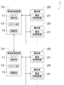
- FIG. 1 is a block diagram of a transport system according to one embodiment of the present invention
- FIG. The schematic side view which shows the structure of a conveyance vehicle.
- FIG. 2 is a schematic plan view showing each region configured by tracks;
- FIG. 2 is a schematic plan view showing lines forming an intermediate connection area and a processing area where congestion is likely to occur; 4 is a flowchart showing a process of judging congestion and alleviating congestion; A time chart showing the counting time of the number of counts.
- FIG. 11 is a schematic plan view showing a route along which the transport vehicle travels after processing for alleviating congestion is performed;
- the transport system 1 shown in FIG. 1 is installed in a facility such as a semiconductor manufacturing factory or distribution warehouse, and transports goods.
- An article transported by the transport system 1 is a container for storing wafers (semiconductor wafers).
- the container is a FOUP (Front-Opening Unified Pod) or a wafer cassette.
- the article may be a reticle pod that houses a reticle.
- the transport system 1 is provided in a distribution warehouse, the articles are products, parts, or the like stored in the distribution warehouse.
- the transportation system 1 includes a management control device 10, a transportation vehicle 20, and a track 30.
- the management control device 10 is a computer having an arithmetic device such as a CPU, a storage device such as an HDD, SSD, or flash memory, and a communication device.
- the management control device 10 can perform various controls related to the transportation and processing of articles by reading and executing programs stored in the storage device.
- the computer can be operated as the route selection section 11, the counting section 12, and the adjustment section 13 by cooperation of the hardware and software described above. Note that these operations will be described later.
- the management control device 10 can transmit a transport command to the transport vehicle 20 using a communication device.
- a transport command is a command that requests the transport vehicle 20 to transport an article.
- the transport command includes, for example, the recipient of the goods and the delivery destination of the goods.
- the transport system 1 includes multiple management control devices 10 .
- Each management control device 10 manages a plurality of transport vehicles 20 .
- the management control device 10 can wirelessly communicate with the transport vehicle 20 that it manages.
- the number of the management control apparatus 10 which comprises the conveyance system 1 may be one.
- the transport vehicle 20 is an OHT (Overhead Hoist Transfer).
- the transport vehicle 20 is a vehicle that unmannedly travels along a track 30 suspended from the ceiling 100 to transport articles.
- the transport system 1 includes a plurality of transport vehicles 20 .
- a plurality of processing equipments 91 are installed in a semiconductor manufacturing factory.
- the processing equipment 91 is located near the track 30 and is accessible by the transport vehicle 20 traveling along the track 30 .
- the processing device 91 has a placement section 92 that receives the article 40 from the carrier 20 .
- the processing apparatus 91 takes in the article 40 placed on the placing section 92 and performs processing (for example, one process for manufacturing a semiconductor device) on the wafer accommodated in the article 40 .
- processing for example, one process for manufacturing a semiconductor device
- a storage shelf or the like for storing the articles 40 is provided instead of the processing device 91 .
- the transport vehicle 20 includes a transport control device 21 , a travel section 22 , a transport section 23 and a housing 28 .
- the transport control device 21 is a computer having an arithmetic device such as a CPU, a storage device such as an HDD, SSD, or flash memory, and a communication device.
- the transport control device 21 controls each part of the transport vehicle 20 by reading and executing a program stored in the storage device.
- the communication device can communicate with the management control device 10 by wire or wirelessly.
- the travel unit 22 includes a travel motor and wheels.
- the travel motor generates rotational driving force under the control of the transport control device 21 .
- the transport vehicle 20 travels along the track 30 by rotating the wheels by the rotational driving force generated by the traveling motor.
- the transport section 23 includes a winding mechanism 24, a suspension belt 25, and a grip section 26.
- the winding mechanism 24 has an elevating motor.
- the winding mechanism 24 can wind and unwind the suspension belt 25 using the driving force generated by the lifting motor.
- a grip portion 26 is connected to the lower end of the suspension belt 25 .
- the gripping section 26 can switch between a state of gripping the article 40 and a state of releasing the grip of the article 40 .
- the article 40 can be received by lowering the article 40 with the hanging belt 25 and gripping the article 40 with the gripping portion 26 .
- the article 40 is lowered by the suspension belt 25 and the article 40 is released from the gripping of the gripping section 26, thereby delivering the article 40 to the placement section 92. can be done.
- the gripping portion 26 may grip the side surface or the bottom surface of the article 40 .
- the transport unit 23 is not limited to a configuration that grips and transports the article 40 , and may have a configuration that includes a transport table on which the article 40 is placed and transported.
- the track 30 of this embodiment is one-way, and the traveling direction of the transport vehicle 20 is predetermined.
- the arrows shown in FIG. 3 indicate the running direction of each track 30 .
- the track 30 is not limited to one-way traffic, and may be bi-directional.
- the area configured by the trajectory 30 can be divided into a processing area and a connection area.
- the processing area is an area mainly for processing the articles 40 , and is an area in which the processing devices 91 are arranged along the track 30 .
- the main purpose of the processing area may be to process the article 40, and the processing area may be used to convey the article 40 as a supplement.
- the processing area includes multiple intrabays.
- An intrabay is an area provided so that load ports in a plurality of processing units 91 face each other.
- the connection area is an area that connects the processing areas and is mainly used for transporting the article 40 . It is sufficient that the main purpose of the connection area is to transport the article 40, and a small number of processing devices 91 may be arranged in the connection area.
- the connection area includes multiple interbays.
- An interbay is an orbital orbit connected to multiple intrabays.
- the transport system 1 includes a first connection area 41, a second connection area 42, and an intermediate connection area 43 as connection areas.
- the first connection area 41, the second connection area 42, and the intermediate connection area 43 each correspond to an interbay.
- the first connection region 41 is arranged on the first side (upper side in the drawing) with the intermediate connection region 43 interposed therebetween, and the second side (lower side in the drawing) opposite to the first side with the intermediate connection region 43 interposed therebetween is arranged. ) is arranged with the second connection region 42 .
- the distance from the first connection region 41 to the intermediate connection region 43 and the distance from the second connection region 42 to the intermediate connection region 43 are the same, but may be different.
- connection regions may be one, two, or four or more.
- the longitudinal directions of the first connection region 41, the second connection region 42, and the intermediate connection region 43 are parallel to each other.
- at least two longitudinal directions of the plurality of connection regions may be perpendicular in plan view.
- the transport system 1 includes a plurality of first processing areas 45 and a plurality of second processing areas 46 as processing areas.
- the first processing area 45 and the second processing area 46 each correspond to an intrabay.
- the first processing area 45 is arranged between the first connection area 41 and the intermediate connection area 43 in plan view, and is connected to both the first connection area 41 and the intermediate connection area 43 .
- the first processing regions 45 are arranged side by side in one direction (longitudinal direction of the first connection region 41 and the like).
- the second processing area 46 is arranged between the second connection area 42 and the intermediate connection area 43 in plan view, and is connected to both the second connection area 42 and the intermediate connection area 43 .
- the second processing regions 46 are arranged side by side in one direction (longitudinal direction of the first connection region 41 and the like). Moreover, the longitudinal direction of the first processing region 45 and the second processing region 46 is perpendicular to the longitudinal direction of the first connection region 41 and the like.
- the intermediate connection region 43 includes a first line 43a, a second line 43b, a connection line 43c, and a shortcut 43d.
- the first track 43 a is the track 30 arranged along the longitudinal direction of the intermediate connection region 43 .
- the first line 43 a may include a path that is inclined or curved with respect to the longitudinal direction of the intermediate connection region 43 .
- the first lines 43a of the present embodiment are arranged so that two lines form one set.
- the article 40 can be efficiently conveyed.
- the transportation vehicle 20 avoids the congestion via the second first track 43a, thereby shortening the transportation time of the article 40.
- the second track 43b is the track 30 arranged parallel to the first track 43a.
- the description regarding the first line 43a is also applied to the second line 43b unless contradictory.
- connection paths 43c are arranged on one side and the other side (left side and right side in FIG. 4) in the longitudinal direction of the first line 43a and the second line 43b, respectively.
- One connection path 43c is a track 30 that connects the ends of the first line 43a and the second line 43b on one side in the longitudinal direction.
- the other connection path 43c is the track 30 that connects the ends of the first line 43a and the second line 43b on the other side in the longitudinal direction.
- the shortcut 43d is the track 30 that connects the longitudinal middle portion of the first line 43a and the longitudinal middle portion of the second line 43b.
- the shortcut 43 d is a route for shortening the traveling distance of the transport vehicle 20 when transporting the article 40 .
- the transport vehicle 20 When the transport vehicle 20 goes from the first connection area 41 to the second connection area 42 , it passes through the intermediate connection area 43 . More specifically, the transport vehicle 20 passes through the first connection area 41, the first processing area 45, the first line 43a, the second line 43b, and the second processing area 46 to the second connection area 42. Moving. Also, when moving from the first track 43a to the second track 43b, it goes through the connection path 43c or the shortcut 43d. However, in order to shorten the traveling distance of the transport vehicle 20, the frequency of selecting the shortcut 43d is high. When going from the second connection area 42 to the first connection area 41, the transport vehicle 20 passes through the above areas or passages in reverse order.
- the shortcuts 43d are not arranged for all the first processing areas 45 (or the second processing areas 46).
- the interval at which the shortcuts 43d are arranged is longer than the interval at which the first processing regions 45 (or the second processing regions 46) are arranged. Therefore, after passing through the shortcut 43d, the transport vehicle 20 passes through a specific second processing region 46 closest to the shortcut 43d (for example, the second processing region 46 shown on the right side of FIG. 4) for the second connection. It often moves to area 42. As a result, congestion occurs in the specific second processing area 46, the transport vehicle 20 stops or moves at a low speed, and transport efficiency decreases.
- the transport vehicle 20 moves from the second connection area 42 to the first connection area 41, it can move to the first connection area 41 via the specific first processing area 45 closest to the shortcut 43d. There are many. As a result, congestion is likely to occur in this specific first processing area 45 .
- the management control device 10 of this embodiment manages one first processing area 45 (or one second processing area 46). Also, as described above, each management control device 10 manages the transport vehicle 20 within its own managed area.
- the management control device 10 When it becomes necessary to transport the article 40 by the transport vehicle 20, the management control device 10 transmits a transport command to the transport vehicle 20 managed by itself. Further, the route selection unit 11 of the management control device 10 selects a route through which the transport vehicle 20 travels from the departure point to the destination.
- the route selection unit 11 selects the route using the cost. Since route search using costs is well known, it will be briefly described below. A cost is set for each route. For example, the longer the route, the higher the cost of this route. Also, even if the length of the route is the same, the cost of the curved route is higher than the cost of the straight route. The route selection unit 11 selects a route so as to minimize the total cost of routes passing from the departure point to the destination.
- a predetermined area is set and congestion in the area is determined.
- This area is hereinafter referred to as a set area.
- all the first processing regions 45 are individually set as set regions, and all the second processing regions 46 are individually set as set regions. Only the specific first processing area 45 or the specific second processing area 46 may be set as the setting area. For example, it is preferable to set at least the first processing area 45 and the second processing area 46 closest to the shortcut 43d (the first processing area to be passed after passing through the shortcut 43d) as setting areas.
- Each management control device 10 performs the processing shown in FIG. 5 with respect to the first processing area 45 or the second processing area 46 managed by itself.
- the counting unit 12 of the management control device 10 counts the transport vehicles 20 entering the set area (S101). For example, the counting unit 12 determines that the guided vehicle 20 has entered the set area when the guided vehicle 20 has passed through the approach route 46a shown in FIG.
- the approach route 46 a is a route that connects the intermediate connection area 43 and the second processing area 46 . However, the count may be based on whether or not a predetermined position on the downstream side of the entry route 46a has been passed.
- the counting unit 12 can grasp the position of the transport vehicle 20 managed by the management control device 10 based on the control details. In addition, regarding the transport vehicle 20 managed by another management control device 10, the position of the transport vehicle 20 can be grasped based on the notification from the other management control device 10 or a higher-level control device.
- a sensor for detecting the guided vehicles 20 may be provided on the approach route 46a, and the counting unit 12 may count the guided vehicles 20 that have passed through the approach route 46a based on the detection result of this sensor. Further, the counting unit 12 may count the guided vehicles 20 that have passed through the approach route 46 a based on the position information received from the guided vehicles 20 .
- the counting period is a period during which the number of guided vehicles 20 entering the set area is counted.
- the aggregation period is set.
- the aggregation period is a predetermined period (for example, several minutes), and is updated as appropriate.
- parts of two temporally adjacent aggregation periods temporally overlap. For example, part of the first aggregation period and part of the second aggregation period temporally overlap. Note that this aggregation period is an example, and for example, each aggregation period does not have to overlap in terms of time.
- the management control device 10 determines whether or not the total count value in the aggregation period exceeds the first threshold (S103).
- a total count value is a value obtained by totaling the number of counts in the total period.
- the total count value is, for example, the total number of counts in the total period, but may be the time average value of the number of counts in the total period.
- the counting may be performed by increasing the weight of the count number as the time zone closer to the current time is.
- the total count value is a value related to the congestion of the set area from the past to the present. Therefore, compared to a value relating to congestion at a point in time, the aggregated count value may represent the congestion situation more accurately. For example, even if the set area is congested at a certain point in time, if the total count value is small, there is a high possibility that the congestion of the set area is being resolved. Therefore, by using the total count value, it is possible to more accurately determine the congestion status of the set area at present and in the near future.
- the first threshold it can be determined by the following method. That is, in experiments, simulations, or actual operations, the correlation between the total count value and the congestion state of the set area is obtained, and the first threshold value is set based on the total count value corresponding to the case where the congestion state of the set area is high. can decide.
- the management control device 10 determines whether the number of guided vehicles 20 located in the set area has exceeded the second threshold (S104).
- the management control device 10 can identify the transport vehicle 20 located in the set area by the same method as in step S101.
- the second threshold is a threshold for determining whether the set area is currently congested. Therefore, the second threshold is set to, for example, the number of guided vehicles 20 when the set area is so congested that the speed of the guided vehicles 20 traveling in the set area decreases, or a certain number less than that. At least one of the first threshold and the second threshold may be changeable by the user or provider of the transport system 1 . Note that the determination using the second threshold is auxiliary and can be omitted.
- the adjustment unit 13 of the management control device 10 determines that the threshold is exceeded in both the determinations of steps S103 and S104, it sets the cost of the route entering the set area (for example, the approach route 46a) to "high”. (S105).
- the cost of the route to enter the set area is divided into two levels: "normal” and "high", which is higher than normal. Therefore, when the cost is changed to "high” in the "normal” state, the cost increases. This increases the cost of routes through the set area.
- the adjustment unit 13 sets the cost of the route entering the set area to "normal" (S106). That is, when the congestion in the set area is resolved (or when there is a sign of resolution), the route cost returns from "high" to "normal.”
- the adjustment unit 13 may change the cost of the route within the set area instead of changing the cost of the route entering the set area. Since the cost of the route passing through the set area increases regardless of which one is changed, the number of guided vehicles 20 traveling in the set area can be changed.
- the management control device 10 When the cost is changed in steps S105 and S106, the management control device 10 notifies the cost change (S107). Specifically, the management control device 10 notifies all the transport vehicles 20 managed by itself of the cost change. Further, the management control device 10 notifies other management control devices 10 of the change in cost. After that, the other management control devices 10 notify the transport vehicles 20 that they manage of the change in cost. Note that this notification method is an example, and for example, all management control devices 10 may be notified via a higher-level control device. Alternatively, if the transport vehicle 20 does not need to store the cost, notification of the cost to the transport vehicle 20 may be omitted. After that, the management control device 10 shifts to the next aggregation period (S108), and repeats the processing from step S101 to step S107.
- S108 next aggregation period
- the route selection unit 11 selects a route that does not pass through the approach route 461a even if it takes a detour, because the cost increases if the approach route 461a is selected.
- the route passing through the second processing area 462 instead of the second processing area 461 is selected.
- the route selection unit 11 selects a route passing through the approach route 461a.
- the route selection unit 11 determines that the route that passes through the approach route 461a is already set. It may be determined whether it is time to change to a route that does not exist. Then, if it is determined that it will be in time, the route may be changed to a route that does not pass through the approach route 461a. As a result, congestion in the second processing area 461 can be alleviated more quickly.
- the transport system 1 of this embodiment includes the transport vehicle 20 and the management control device 10 .
- the transport vehicle 20 transports the article 40 by running along the track 30 .
- the management control device 10 assigns a transport command for the article 40 to the transport vehicle 20 .
- the transport system 1 of this embodiment includes a route selector 11 , a counter 12 and an adjuster 13 .
- the route selection unit 11 selects a route for the transport vehicle 20 to minimize the cost of the route from the departure point to the destination based on the transport command.
- the counting unit 12 counts the number of guided vehicles 20 entering a set area set on the track 30 .
- the adjusting unit 13 increases the cost of the route passing through the set area when the total count value obtained by totaling the count numbers of the counting unit 12 in the total period exceeds the first threshold.
- the aggregated count value is data related to congestion from the past to the time of aggregation, it is an effective indicator of the occurrence of congestion in the transport vehicle 20 . Therefore, by increasing the cost of passing through the route based on the total count value, it is possible to accurately determine the state of congestion and alleviate the congestion of the transport vehicle 20 .
- the adjustment unit 13 determines whether or not the total count value in the first total period exceeds the first threshold, and then determines whether or not the total count value in the second total period exceeds the threshold. determine whether Part of the first aggregation period and part of the second aggregation period temporally overlap.
- the adjustment unit 13 sets the Increases the cost of routes through the region.
- a plurality of set areas are set in the transport system 1 of the present embodiment.
- the counting unit 12 counts the number of guided vehicles 20 entering each set area.
- congestion can be alleviated at multiple locations. Also, when the cost of a route passing through a certain set area increases and another set area becomes congested, the congestion in the newly congested set area can be alleviated.
- processing devices 91 are arranged along the track 30 .
- the processing device 91 processes the article 40 transported by the transport vehicle 20 .
- the area defined by track 30 includes a processing area and a connection area.
- the processing area is an area in which the processing device 91 is arranged.
- a connection area connects the processing areas.
- the setting area includes at least part of the processing area.
- the counting unit 12 counts the number of guided vehicles 20 entering the set area from the connection area.
- connection area includes the first track 43a, the second track 43b, the connection path 43c, and the shortcut 43d.
- the second line 43b is arranged parallel to the first line 43a.
- the connection path 43c connects the ends on the same side of the first line 43a and the second line 43b.
- the shortcut 43d is provided separately from the connection path 43c and connects the middle portion of the first line 43a and the middle portion of the second line 43b.
- the set area includes at least part of the processing area closest to the shortcut 43d among the plurality of processing areas.
- the connection area includes the intermediate connection area 43, the first connection area 41, and the second connection area 42.
- the intermediate connection region 43 includes a first line 43a, a second line 43b, a connection line 43c and a shortcut 43d.
- the first connection region 41 is arranged on the first side in a plan view across the intermediate connection region 43 .
- the second connection region 42 is arranged on the second side opposite to the first side in a plan view across the intermediate connection region 43 .
- the processing area includes a plurality of first processing areas 45 and a plurality of second processing areas 46 .
- the first processing region 45 is connected to the first connection region 41 and to the first line 43 a of the intermediate connection region 43 .
- the second processing region 46 is connected to the second connection region 42 and to the second line 43 b of the intermediate connection region 43 .
- the set regions include at least one first processing region 45 closest to the shortcut 43d and at least one second processing region 46 closest to the shortcut 43d.
- the transport vehicle 20 heading from the first connection area 41 to the second connection area 42 mainly passes through shortcuts and through processing areas near the shortcuts, so congestion is likely to occur in these processing areas. Therefore, by including these processing areas in the set area, the congestion can be appropriately alleviated.
- This embodiment includes features 1 to 7 below.
- a transport vehicle that transports articles by traveling along a track; a management control device that assigns a transport command for the article to the transport vehicle;
- a transport system comprising: a route selection unit that selects a route on which the transport vehicle travels based on the transport command so as to minimize the cost of the route from the departure point to the destination; a counting unit that counts the number of the guided vehicles entering a set area set on the track; an adjustment unit that increases the cost of a route that passes through the set area when a count aggregate value obtained by aggregating the count numbers of the counting unit in the aggregation period exceeds a first threshold;
- a transport system comprising: [Feature 2] The transport system according to feature 1, The adjusting unit, after determining whether the count aggregate value in the first aggregation period exceeds the first threshold value, determines whether the count aggregate value in the second aggregation period exceeds the threshold value, A transport system, wherein a part of the first aggregation period and a
- [Feature 3] The transport system according to feature 1 or 2, The adjustment unit adjusts a route passing through the set area when the total count value exceeds the first threshold and when the number of the guided vehicles located in the set area exceeds a second threshold.
- a transport system characterized by increasing the cost of [Feature 4] A transport system according to any one of features 1 to 3, A plurality of said setting areas are set, The conveying system, wherein the counting unit counts the number of the conveying vehicles that enter the set area for each of the set areas.
- a transport system according to any one of features 1 to 4, A processing device is arranged along the trajectory, The processing device processes the article transported by the transport vehicle,
- the region configured by the trajectory is a processing area, which is an area in which the processing device is arranged; a connection area that connects the processing areas; including
- the setting area includes at least part of the processing area,
- connection area is a first line; a second line arranged parallel to the first line; a connection path that connects end portions on the same side of the first line and the second line; a shortcut that is provided separately from the connection path and connects an intermediate portion of the first line and an intermediate portion of the second line; including The transport system, wherein the set area includes at least part of the processing area closest to the shortcut among the plurality of processing areas.
- connection area is an intermediate connection area including the first line, the second line, the connection path, and the shortcut; a first connection region arranged on the first side in plan view across the intermediate connection region; a second connection region disposed on a second side opposite to the first side in plan view across the intermediate connection region; including
- the processing area is a plurality of first processing regions connected to the first connection region and connected to the first line of the intermediate connection region; a plurality of second processing regions connected to the second connection region and connected to the second line of the intermediate connection region; including The transport system, wherein the set areas include at least one of the first processing areas closest to the shortcut and at least one of the second processing areas closest to the shortcut.
- the route selection unit 11, the count unit 12, and the adjustment unit 13 are provided in the management control device 10.
- at least one of these may be provided in the transport vehicle 20 (transport control device 21). That is, the process of judging and alleviating congestion may be performed by the management control device 10 or by the transport vehicle 20 .
- the area is divided into the connection area and the processing area, and the processing area is the setting area, but the setting area in the above embodiment is an example.
- the connection area may be set as the setting area, or part of the processing area or part of the connection area may be set as the setting area.
- the tracks 30 and the processing devices 91 may be arranged so that the connecting area and the processing area cannot be clearly divided.
- the layout of the track 30 is an example, and is not limited to the layout shown in the above embodiment.
- the layout may be such that a plurality of processing areas are connected to each other by a plurality of lines (connection areas). In this case, when one line is congested, the cost of that line increases, and other lines are preferentially used.
Landscapes
- Engineering & Computer Science (AREA)
- Business, Economics & Management (AREA)
- Physics & Mathematics (AREA)
- General Physics & Mathematics (AREA)
- Aviation & Aerospace Engineering (AREA)
- Radar, Positioning & Navigation (AREA)
- Remote Sensing (AREA)
- Automation & Control Theory (AREA)
- Economics (AREA)
- Human Resources & Organizations (AREA)
- Strategic Management (AREA)
- Mechanical Engineering (AREA)
- Development Economics (AREA)
- Entrepreneurship & Innovation (AREA)
- Marketing (AREA)
- Operations Research (AREA)
- Quality & Reliability (AREA)
- Tourism & Hospitality (AREA)
- General Business, Economics & Management (AREA)
- Theoretical Computer Science (AREA)
- Transportation (AREA)
- Game Theory and Decision Science (AREA)
- Control Of Position, Course, Altitude, Or Attitude Of Moving Bodies (AREA)
Priority Applications (5)
| Application Number | Priority Date | Filing Date | Title |
|---|---|---|---|
| EP22918690.3A EP4462216A4 (en) | 2022-01-07 | 2022-09-01 | TRANSPORTATION SYSTEM |
| KR1020247021318A KR20240116769A (ko) | 2022-01-07 | 2022-09-01 | 반송 시스템 |
| JP2023572348A JP7811342B2 (ja) | 2022-01-07 | 2022-09-01 | 搬送システム |
| US18/726,663 US20250083710A1 (en) | 2022-01-07 | 2022-09-01 | Transport system |
| CN202280086215.2A CN118489094A (zh) | 2022-01-07 | 2022-09-01 | 搬送系统 |
Applications Claiming Priority (2)
| Application Number | Priority Date | Filing Date | Title |
|---|---|---|---|
| JP2022001966 | 2022-01-07 | ||
| JP2022-001966 | 2022-01-07 |
Publications (1)
| Publication Number | Publication Date |
|---|---|
| WO2023132101A1 true WO2023132101A1 (ja) | 2023-07-13 |
Family
ID=87073372
Family Applications (1)
| Application Number | Title | Priority Date | Filing Date |
|---|---|---|---|
| PCT/JP2022/032986 Ceased WO2023132101A1 (ja) | 2022-01-07 | 2022-09-01 | 搬送システム |
Country Status (7)
| Country | Link |
|---|---|
| US (1) | US20250083710A1 (https=) |
| EP (1) | EP4462216A4 (https=) |
| JP (1) | JP7811342B2 (https=) |
| KR (1) | KR20240116769A (https=) |
| CN (1) | CN118489094A (https=) |
| TW (1) | TW202333015A (https=) |
| WO (1) | WO2023132101A1 (https=) |
Cited By (2)
| Publication number | Priority date | Publication date | Assignee | Title |
|---|---|---|---|---|
| WO2025126530A1 (ja) * | 2023-12-12 | 2025-06-19 | 村田機械株式会社 | 搬送車システム |
| WO2025126534A1 (ja) * | 2023-12-12 | 2025-06-19 | 村田機械株式会社 | 走行車システム |
Families Citing this family (1)
| Publication number | Priority date | Publication date | Assignee | Title |
|---|---|---|---|---|
| CN117035602B (zh) * | 2023-10-10 | 2023-12-15 | 成都思越智能装备股份有限公司 | 一种跨搬运系统的物料搬送路径寻优方法及装置 |
Citations (6)
| Publication number | Priority date | Publication date | Assignee | Title |
|---|---|---|---|---|
| JP2006195859A (ja) * | 2005-01-17 | 2006-07-27 | Murata Mach Ltd | 搬送車システム |
| JP2020030723A (ja) * | 2018-08-24 | 2020-02-27 | 村田機械株式会社 | 走行車制御装置、走行車システム、及び走行車制御方法 |
| CN111762519A (zh) * | 2020-04-22 | 2020-10-13 | 北京京东乾石科技有限公司 | 引导拣选机器人作业的方法、系统和调度装置 |
| WO2021039210A1 (ja) * | 2019-08-26 | 2021-03-04 | 日本電気株式会社 | 搬送システム、制御装置、搬送方法及びプログラム |
| JP2021039450A (ja) * | 2019-08-30 | 2021-03-11 | パナソニックIpマネジメント株式会社 | 設計支援システム、設計支援方法、及びプログラム |
| JP2021076970A (ja) | 2019-11-06 | 2021-05-20 | 株式会社ダイフク | 物品搬送設備 |
Family Cites Families (6)
| Publication number | Priority date | Publication date | Assignee | Title |
|---|---|---|---|---|
| JP5055052B2 (ja) * | 2007-07-20 | 2012-10-24 | クラリオン株式会社 | 経路探索システム、データ処理装置、データ配信装置、ナビゲーション装置 |
| JP5686501B2 (ja) * | 2009-03-27 | 2015-03-18 | 株式会社ダイフク | 物品搬送設備 |
| US20170169373A1 (en) * | 2015-12-14 | 2017-06-15 | Xerox Corporation | System and method for measuring perceived impact of schedule deviation in public transport |
| US12572150B2 (en) * | 2019-11-05 | 2026-03-10 | Strong Force Vcn Portfolio 2019, Llc | Robot fleet management for value chain networks |
| CN114341026B (zh) * | 2019-11-07 | 2023-10-03 | 村田机械株式会社 | 搬运系统及网格系统 |
| EP4337467A4 (en) * | 2021-05-11 | 2025-05-07 | Strong Force VCN Portfolio 2019, LLC | SYSTEMS, METHODS, KITS AND APPARATUSES FOR STORAGE AND QUERY DISTRIBUTED AT THE EDGE IN VALUE CHAIN NETWORKS |
-
2022
- 2022-09-01 EP EP22918690.3A patent/EP4462216A4/en active Pending
- 2022-09-01 KR KR1020247021318A patent/KR20240116769A/ko active Pending
- 2022-09-01 US US18/726,663 patent/US20250083710A1/en active Pending
- 2022-09-01 WO PCT/JP2022/032986 patent/WO2023132101A1/ja not_active Ceased
- 2022-09-01 JP JP2023572348A patent/JP7811342B2/ja active Active
- 2022-09-01 CN CN202280086215.2A patent/CN118489094A/zh active Pending
-
2023
- 2023-01-05 TW TW112100312A patent/TW202333015A/zh unknown
Patent Citations (6)
| Publication number | Priority date | Publication date | Assignee | Title |
|---|---|---|---|---|
| JP2006195859A (ja) * | 2005-01-17 | 2006-07-27 | Murata Mach Ltd | 搬送車システム |
| JP2020030723A (ja) * | 2018-08-24 | 2020-02-27 | 村田機械株式会社 | 走行車制御装置、走行車システム、及び走行車制御方法 |
| WO2021039210A1 (ja) * | 2019-08-26 | 2021-03-04 | 日本電気株式会社 | 搬送システム、制御装置、搬送方法及びプログラム |
| JP2021039450A (ja) * | 2019-08-30 | 2021-03-11 | パナソニックIpマネジメント株式会社 | 設計支援システム、設計支援方法、及びプログラム |
| JP2021076970A (ja) | 2019-11-06 | 2021-05-20 | 株式会社ダイフク | 物品搬送設備 |
| CN111762519A (zh) * | 2020-04-22 | 2020-10-13 | 北京京东乾石科技有限公司 | 引导拣选机器人作业的方法、系统和调度装置 |
Non-Patent Citations (1)
| Title |
|---|
| See also references of EP4462216A4 |
Cited By (2)
| Publication number | Priority date | Publication date | Assignee | Title |
|---|---|---|---|---|
| WO2025126530A1 (ja) * | 2023-12-12 | 2025-06-19 | 村田機械株式会社 | 搬送車システム |
| WO2025126534A1 (ja) * | 2023-12-12 | 2025-06-19 | 村田機械株式会社 | 走行車システム |
Also Published As
| Publication number | Publication date |
|---|---|
| TW202333015A (zh) | 2023-08-16 |
| EP4462216A4 (en) | 2025-12-03 |
| US20250083710A1 (en) | 2025-03-13 |
| JPWO2023132101A1 (https=) | 2023-07-13 |
| JP7811342B2 (ja) | 2026-02-05 |
| KR20240116769A (ko) | 2024-07-30 |
| CN118489094A (zh) | 2024-08-13 |
| EP4462216A1 (en) | 2024-11-13 |
Similar Documents
| Publication | Publication Date | Title |
|---|---|---|
| WO2023132101A1 (ja) | 搬送システム | |
| JP4366663B2 (ja) | 搬送台車システム | |
| JP4766111B2 (ja) | 搬送車システム | |
| TWI817010B (zh) | 搬送控制裝置 | |
| JP2003146412A (ja) | 搬送システム | |
| CN114379972A (zh) | 输送系统 | |
| JPWO2017029873A1 (ja) | 搬送車システム | |
| WO2020049872A1 (ja) | 搬送車システム | |
| KR102608150B1 (ko) | 반송 시스템 및 반송 제어 방법 | |
| WO2019176352A1 (ja) | 走行車コントローラ及び走行車システム | |
| TWI788676B (zh) | 轉運器控制裝置及具有其之系統 | |
| JP4441931B2 (ja) | 搬送台車システム | |
| US8521406B2 (en) | Traveling vehicle system | |
| JP7306588B2 (ja) | 走行車システム及び走行車の制御方法 | |
| JP4441914B2 (ja) | 搬送システム | |
| JP4427755B2 (ja) | 搬送システム | |
| JP2016113250A (ja) | バッファシステム及び物品のバッファ方法 | |
| JP4705757B2 (ja) | 半導体集積回路装置の製造方法 | |
| JP4389225B2 (ja) | 搬送システム | |
| JP2010282567A (ja) | 搬送車システム | |
| JP4172464B2 (ja) | 搬送台車システム | |
| TW202601473A (zh) | 物品搬送設備 | |
| KR20240077309A (ko) | 물류 반송 장치 및 물류 반송 방법 | |
| JP2010218380A (ja) | 搬送車システム |
Legal Events
| Date | Code | Title | Description |
|---|---|---|---|
| 121 | Ep: the epo has been informed by wipo that ep was designated in this application |
Ref document number: 22918690 Country of ref document: EP Kind code of ref document: A1 |
|
| WWE | Wipo information: entry into national phase |
Ref document number: 2023572348 Country of ref document: JP |
|
| ENP | Entry into the national phase |
Ref document number: 20247021318 Country of ref document: KR Kind code of ref document: A |
|
| WWE | Wipo information: entry into national phase |
Ref document number: 202280086215.2 Country of ref document: CN Ref document number: 1020247021318 Country of ref document: KR |
|
| WWE | Wipo information: entry into national phase |
Ref document number: 18726663 Country of ref document: US |
|
| WWE | Wipo information: entry into national phase |
Ref document number: 11202404522Q Country of ref document: SG |
|
| WWE | Wipo information: entry into national phase |
Ref document number: 2022918690 Country of ref document: EP |
|
| NENP | Non-entry into the national phase |
Ref country code: DE |
|
| ENP | Entry into the national phase |
Ref document number: 2022918690 Country of ref document: EP Effective date: 20240807 |
|
| WWP | Wipo information: published in national office |
Ref document number: 18726663 Country of ref document: US |
|
| WWG | Wipo information: grant in national office |
Ref document number: 11202404522Q Country of ref document: SG |
|
| WWP | Wipo information: published in national office |
Ref document number: 11202404522Q Country of ref document: SG |