WO2023127265A1 - 生成装置 - Google Patents
生成装置 Download PDFInfo
- Publication number
- WO2023127265A1 WO2023127265A1 PCT/JP2022/040134 JP2022040134W WO2023127265A1 WO 2023127265 A1 WO2023127265 A1 WO 2023127265A1 JP 2022040134 W JP2022040134 W JP 2022040134W WO 2023127265 A1 WO2023127265 A1 WO 2023127265A1
- Authority
- WO
- WIPO (PCT)
- Prior art keywords
- cathode
- anode
- chamber
- diaphragm
- side diaphragm
- Prior art date
Links
- 238000005192 partition Methods 0.000 claims abstract description 52
- XLYOFNOQVPJJNP-UHFFFAOYSA-N water Substances O XLYOFNOQVPJJNP-UHFFFAOYSA-N 0.000 claims description 88
- 239000012528 membrane Substances 0.000 claims description 45
- 238000007789 sealing Methods 0.000 claims description 31
- 238000007599 discharging Methods 0.000 claims description 10
- 239000000835 fiber Substances 0.000 claims description 4
- FAPWRFPIFSIZLT-UHFFFAOYSA-M Sodium chloride Chemical compound [Na+].[Cl-] FAPWRFPIFSIZLT-UHFFFAOYSA-M 0.000 description 23
- HEMHJVSKTPXQMS-UHFFFAOYSA-M Sodium hydroxide Chemical compound [OH-].[Na+] HEMHJVSKTPXQMS-UHFFFAOYSA-M 0.000 description 15
- 238000005868 electrolysis reaction Methods 0.000 description 13
- 230000002093 peripheral effect Effects 0.000 description 8
- QWPPOHNGKGFGJK-UHFFFAOYSA-N hypochlorous acid Chemical compound ClO QWPPOHNGKGFGJK-UHFFFAOYSA-N 0.000 description 6
- 238000004519 manufacturing process Methods 0.000 description 5
- 235000011121 sodium hydroxide Nutrition 0.000 description 5
- 239000000460 chlorine Substances 0.000 description 4
- 229920003002 synthetic resin Polymers 0.000 description 4
- 239000000057 synthetic resin Substances 0.000 description 4
- -1 Chlorine ions Chemical class 0.000 description 3
- 230000005856 abnormality Effects 0.000 description 3
- 239000007864 aqueous solution Substances 0.000 description 2
- 229910052801 chlorine Inorganic materials 0.000 description 2
- 239000008151 electrolyte solution Substances 0.000 description 2
- 239000003014 ion exchange membrane Substances 0.000 description 2
- 238000012423 maintenance Methods 0.000 description 2
- 239000012266 salt solution Substances 0.000 description 2
- 239000011734 sodium Substances 0.000 description 2
- 239000011780 sodium chloride Substances 0.000 description 2
- KZBUYRJDOAKODT-UHFFFAOYSA-N Chlorine Chemical compound ClCl KZBUYRJDOAKODT-UHFFFAOYSA-N 0.000 description 1
- 239000002253 acid Substances 0.000 description 1
- 230000002378 acidificating effect Effects 0.000 description 1
- 238000005452 bending Methods 0.000 description 1
- 238000001514 detection method Methods 0.000 description 1
- 238000000746 purification Methods 0.000 description 1
- 229910001415 sodium ion Inorganic materials 0.000 description 1
- 239000000126 substance Substances 0.000 description 1
- 239000008399 tap water Substances 0.000 description 1
- 235000020679 tap water Nutrition 0.000 description 1
Images


Classifications
-
- C—CHEMISTRY; METALLURGY
- C02—TREATMENT OF WATER, WASTE WATER, SEWAGE, OR SLUDGE
- C02F—TREATMENT OF WATER, WASTE WATER, SEWAGE, OR SLUDGE
- C02F1/00—Treatment of water, waste water, or sewage
- C02F1/46—Treatment of water, waste water, or sewage by electrochemical methods
- C02F1/461—Treatment of water, waste water, or sewage by electrochemical methods by electrolysis
- C02F1/46104—Devices therefor; Their operating or servicing
- C02F1/4618—Devices therefor; Their operating or servicing for producing "ionised" acidic or basic water
-
- C—CHEMISTRY; METALLURGY
- C02—TREATMENT OF WATER, WASTE WATER, SEWAGE, OR SLUDGE
- C02F—TREATMENT OF WATER, WASTE WATER, SEWAGE, OR SLUDGE
- C02F1/00—Treatment of water, waste water, or sewage
- C02F1/46—Treatment of water, waste water, or sewage by electrochemical methods
- C02F1/461—Treatment of water, waste water, or sewage by electrochemical methods by electrolysis
- C02F1/46104—Devices therefor; Their operating or servicing
-
- C—CHEMISTRY; METALLURGY
- C25—ELECTROLYTIC OR ELECTROPHORETIC PROCESSES; APPARATUS THEREFOR
- C25B—ELECTROLYTIC OR ELECTROPHORETIC PROCESSES FOR THE PRODUCTION OF COMPOUNDS OR NON-METALS; APPARATUS THEREFOR
- C25B9/00—Cells or assemblies of cells; Constructional parts of cells; Assemblies of constructional parts, e.g. electrode-diaphragm assemblies; Process-related cell features
- C25B9/70—Assemblies comprising two or more cells
- C25B9/73—Assemblies comprising two or more cells of the filter-press type
- C25B9/77—Assemblies comprising two or more cells of the filter-press type having diaphragms
-
- C—CHEMISTRY; METALLURGY
- C02—TREATMENT OF WATER, WASTE WATER, SEWAGE, OR SLUDGE
- C02F—TREATMENT OF WATER, WASTE WATER, SEWAGE, OR SLUDGE
- C02F1/00—Treatment of water, waste water, or sewage
- C02F1/46—Treatment of water, waste water, or sewage by electrochemical methods
- C02F1/461—Treatment of water, waste water, or sewage by electrochemical methods by electrolysis
- C02F1/467—Treatment of water, waste water, or sewage by electrochemical methods by electrolysis by electrochemical disinfection; by electrooxydation or by electroreduction
- C02F1/4672—Treatment of water, waste water, or sewage by electrochemical methods by electrolysis by electrochemical disinfection; by electrooxydation or by electroreduction by electrooxydation
- C02F1/4674—Treatment of water, waste water, or sewage by electrochemical methods by electrolysis by electrochemical disinfection; by electrooxydation or by electroreduction by electrooxydation with halogen or compound of halogens, e.g. chlorine, bromine
-
- C—CHEMISTRY; METALLURGY
- C02—TREATMENT OF WATER, WASTE WATER, SEWAGE, OR SLUDGE
- C02F—TREATMENT OF WATER, WASTE WATER, SEWAGE, OR SLUDGE
- C02F1/00—Treatment of water, waste water, or sewage
- C02F1/46—Treatment of water, waste water, or sewage by electrochemical methods
- C02F1/461—Treatment of water, waste water, or sewage by electrochemical methods by electrolysis
- C02F1/46104—Devices therefor; Their operating or servicing
- C02F1/4618—Devices therefor; Their operating or servicing for producing "ionised" acidic or basic water
- C02F2001/46185—Devices therefor; Their operating or servicing for producing "ionised" acidic or basic water only anodic or acidic water, e.g. for oxidizing or sterilizing
-
- C—CHEMISTRY; METALLURGY
- C02—TREATMENT OF WATER, WASTE WATER, SEWAGE, OR SLUDGE
- C02F—TREATMENT OF WATER, WASTE WATER, SEWAGE, OR SLUDGE
- C02F2201/00—Apparatus for treatment of water, waste water or sewage
- C02F2201/002—Construction details of the apparatus
- C02F2201/004—Seals, connections
-
- C—CHEMISTRY; METALLURGY
- C02—TREATMENT OF WATER, WASTE WATER, SEWAGE, OR SLUDGE
- C02F—TREATMENT OF WATER, WASTE WATER, SEWAGE, OR SLUDGE
- C02F2201/00—Apparatus for treatment of water, waste water or sewage
- C02F2201/46—Apparatus for electrochemical processes
- C02F2201/461—Electrolysis apparatus
- C02F2201/46105—Details relating to the electrolytic devices
- C02F2201/46115—Electrolytic cell with membranes or diaphragms
-
- Y—GENERAL TAGGING OF NEW TECHNOLOGICAL DEVELOPMENTS; GENERAL TAGGING OF CROSS-SECTIONAL TECHNOLOGIES SPANNING OVER SEVERAL SECTIONS OF THE IPC; TECHNICAL SUBJECTS COVERED BY FORMER USPC CROSS-REFERENCE ART COLLECTIONS [XRACs] AND DIGESTS
- Y02—TECHNOLOGIES OR APPLICATIONS FOR MITIGATION OR ADAPTATION AGAINST CLIMATE CHANGE
- Y02E—REDUCTION OF GREENHOUSE GAS [GHG] EMISSIONS, RELATED TO ENERGY GENERATION, TRANSMISSION OR DISTRIBUTION
- Y02E60/00—Enabling technologies; Technologies with a potential or indirect contribution to GHG emissions mitigation
- Y02E60/30—Hydrogen technology
- Y02E60/36—Hydrogen production from non-carbon containing sources, e.g. by water electrolysis
Definitions
- the present invention relates to a generator that generates electrolyzed water.
- an electrolytic cell is divided into two or three chambers by a pair of cover members for housing electrodes and a partition sandwiched between the cover members via the partition. to generate electrolyzed water.
- the present invention has been made in view of these points, and an object of the present invention is to provide a generator capable of suppressing damage to the diaphragm.
- a generator according to the present invention is a generator that generates electrolyzed water using a pair of electrodes to which power is supplied and a diaphragm, and an electrolytic cell having a plurality of chambers partitioned by the diaphragm; a membrane protection structure for suppressing damage to the diaphragm;
- the membrane protection structure includes a partition sandwiched between the cover members via a partition, and a seal member for water-tightly closing a gap between the cover member and the partition, wherein the membrane protection structure extends from the seal member to the edge of the recess. or a protrusion formed to protrude into the chamber beyond the edge of the opening.
- FIG. 1 is a longitudinal sectional view of a generating device according to a first embodiment
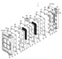
- FIG. Fig. 3 is an exploded perspective view of the same generating device
- FIG. 8 is a sectional view at a position corresponding to II in FIG.
- FIG. 7 It is a cross-sectional view which expands and shows a part of production
- Fig. 2 is a front view showing a membrane protection member of the same generation device;
- FIG. 3 is a vertical cross-sectional view showing part of the same membrane protection member.
- (a) is a perspective view showing an example of the same generation device,
- (b) is a perspective view showing another example of the same generation device.
- FIG. 11 is a perspective view showing a sealing member of a generating device according to a second embodiment;
- 1 indicates a generator that generates electrolyzed water (electrolyzed water generator).
- the generation device 1 is, for example, a three-chamber electrolysis device (hypochlorous acid water generation device ).
- This generation device 1 is equipped with a three-chamber type electrolytic bath (electrolysis cell) 5 .
- the electrolytic cell 5 includes a cathode chamber 6 as one electrode chamber (first electrode chamber), an anode chamber 7 as the other electrode chamber (second electrode chamber), and a position between the cathode chamber 6 and the anode chamber 7. and an intermediate chamber 8 for
- the cathode chamber 6 and the intermediate chamber 8 are partitioned by a cathode-side diaphragm 11 as an ion-exchange membrane, which is one diaphragm (first diaphragm).
- the anode chamber 7 and the intermediate chamber 8 are partitioned by an anode-side diaphragm 12 as an ion-exchange membrane, which is the other diaphragm (second diaphragm). That is, the interior of the electrolytic cell 5 is partitioned into three chambers 6, 7 and 8 by two membranes 11 and 12.
- a flat plate-like anode 14 as the other electrode (second electrode) is provided in the anode chamber 7 , and the anode 14 faces the anode-side diaphragm 12 in close proximity.
- the cathode 13 and the anode 14 are connected to a power source for supplying power.
- the generation device 1 also includes a saline solution supply unit 21 that supplies saline solution, which is an electrolytic solution, to the intermediate chamber (electrolyte solution chamber) 8 of the electrolytic cell 5 .
- the saline solution supply unit 21 includes a tank 22 in which saline solution is stored, a supply pipe 23 for supplying the saline solution in the tank 22 to the intermediate chamber 8, a pump provided in the middle of the supply pipe 23, and an intermediate chamber. and a return pipe 25 for returning the saline solution in the chamber 8 to the tank 22 . It should be noted that the structure is not limited to the circulating structure shown in FIG.
- the generator 1 includes a water supply unit 31 that supplies raw water for electrolysis (for example, tap water passed through a water softener) to the cathode chamber 6 and the anode chamber 7 of the electrolytic cell 5, and the cathode chamber of the electrolytic cell 5. 6 and an electrolyzed water discharge part 32 for discharging the electrolyzed water generated in the anode chamber 7 to the outside of the electrolytic cell 5 .
- raw water for electrolysis for example, tap water passed through a water softener
- the water supply unit 31 has a first supply pipe 33 that supplies water to the cathode chamber 6, which is the first electrode chamber, and a second supply pipe 34 that supplies water to the anode chamber 7, which is the second electrode chamber. ing.
- the electrolyzed water discharge unit 32 includes a first discharge pipe 36 for discharging caustic soda water (NaOH aqueous solution), which is alkaline electrolyzed water generated in the cathode chamber 6, and hypochlorous acid water, which is acidic electrolyzed water generated in the anode chamber 7. and a second discharge pipe 37 for discharging acid water (HClO aqueous solution).
- CaOH aqueous solution caustic soda water
- hypochlorous acid water which is acidic electrolyzed water generated in the anode chamber 7.
- a second discharge pipe 37 for discharging acid water (HClO aqueous solution).
- the generator 1 operates the pump of the saline solution supply unit 21 to supply the saline solution from the supply pipe 23 to the intermediate chamber 8 of the electrolytic cell 5, and the first supply pipe 33 and the second supply pipe of the water supply unit 31 Water is supplied to the cathode chamber 6 and the anode chamber 7 of the electrolytic cell 5 from the supply pipe 34 .
- a negative voltage and a positive voltage are applied from the power source to the cathode 13 and the anode 14, respectively.
- Ionized sodium ions (Na + ) in the saline solution that has flowed into the intermediate chamber 8 are attracted to the cathode 13 , pass through the cathode-side diaphragm 11 , and flow into the cathode chamber 6 . Then, in the cathode chamber 6, water is decomposed by the cathode 13 to obtain caustic soda water as follows.
- Chlorine ions (Cl ⁇ ) ionized in the saline solution in the intermediate chamber 8 are attracted to the anode 14 , pass through the anode-side diaphragm 12 , and flow into the anode chamber 7 . Chlorine ions are reduced at the anode 14 to generate chlorine gas as follows, which reacts with water in the anode chamber 7 to produce hypochlorous acid water.
- the caustic soda water thus generated is discharged from the cathode chamber 6 through the first discharge pipe 36, and the hypochlorous acid water is discharged from the anode chamber 7 through the second discharge pipe 37.
- the generating device 1 is structurally composed of outer plates 41, which are paired cover members, and partition walls 42 sandwiched between the outer plates 41, and seal members 43 and 44. It is configured to be watertightly combined via
- the outer plate 41 includes a cathode outer plate 41 a covering the cathode side diaphragm 11 and the cathode 13 on one side of the partition wall 42 , and an anode outer plate 41 b covering the anode side diaphragm 12 and the anode 14 on the other side of the partition wall 42 . and are set.
- the cathode outer plate 41a and the anode outer plate 41b basically have a symmetrical or substantially symmetrical structure with the partition wall 42 interposed therebetween. , are collectively described as the structure of the outer plate 41 .
- the outer plate 41 is made of synthetic resin or the like and has a square shape when viewed from the front.
- the outer plate 41 has the same or approximately the same outer shape as the bulkhead 42 .
- the outer plate 41 has a rectangular outer shape with its longitudinal direction extending in the vertical direction.
- the cathode 13 and the cathode-side diaphragm 11 are arranged between the cathode outer plate 41 a and the partition 42
- the anode 14 and the anode-side diaphragm 12 are arranged between the anode outer plate 41 b and the partition 42 .
- a concave portion 51 is formed in the side surface of the outer plate 41 on the partition wall 42 side.
- the concave portion 51 is recessed in the thickness direction of the outer plate 41 .
- the recess 51 of the cathode outer plate 41 a forms the cathode chamber 6
- the recess 51 of the anode outer plate 41 b forms the anode chamber 7 .
- recessed portion 51 is formed in a quadrangular shape having a longitudinal direction in the vertical direction.
- the cathode chamber 6 is defined between the recessed portion 51 of the cathode outer plate 41a and the cathode side diaphragm 11
- the anode chamber 7 is defined between the recessed portion 51 of the anode outer plate 41b and the anode side diaphragm 12. .
- the cathode 13 and the cathode-side diaphragm 11 are positioned so as to cover at least the recess 51 of the cathode outer plate 41a, and the anode 14 and the anode-side diaphragm 12 are positioned so as to cover at least the recess 51 of the anode outer plate 41b. .
- the outer plate 41 has a supply port 52 formed at the bottom and a discharge port 53 formed at the top.
- the supply port 52 opens downward, and the discharge port 53 opens upward.
- the supply port 52 is positioned below the recess 51 and the discharge port 53 is positioned above the recess 51 .
- the supply port 52 and the discharge port 53 are located at equal or substantially equal positions in the lateral direction of the outer plate 41 . That is, the supply port 52 and the discharge port 53 are positioned on the same vertical line or substantially on the same vertical line.
- the supply port 52 is connected to the water supply portion 31 and the discharge port 53 is connected to the electrolyzed water discharge portion 32 .
- the supply port 52 and the discharge port 53 of the cathode outer plate 41a are connected to the first supply pipe 33 and the first discharge pipe 36, and the supply port 52 and the discharge port 53 of the anode outer plate 41b are connected to the second supply pipe. It is connected to the pipe 34 and the second discharge pipe 37 .
- the supply port 52 and the recessed portion 51 are connected by a supply piping structure 54 that is a piping structure
- the recessed portion 51 and the discharge port 53 are connected by a discharge piping structure 55 that is a piping structure.
- the supply piping structure 54 and the discharge piping structure 55 are each formed in the outer plate 41 in the shape of a passage. With these structures, water is supplied from the water supply portion 31 to the cathode chamber 6 and the anode chamber 7 from below through the supply port 52 and the supply pipe structure 54, and the generated electrolyzed water is discharged to the discharge pipe structure 55. and discharged from above through the discharge port 53 .
- water is supplied to and discharged from the cathode chamber 6 and the anode chamber 7 along the cathode 13 , anode 14 , cathode side diaphragm 11 and anode side diaphragm 12 .
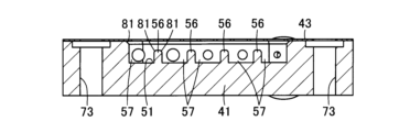
- the outer plate 41 is formed with a branched portion 56 positioned within the recessed portion 51 .
- the branching portion 56 divides the insides of the cathode chamber 6 and the anode chamber 7 in a direction intersecting or perpendicular to the water supply direction and the electrolyzed water discharge direction.
- the branched portion 56 is formed in the shape of a longitudinal rib extending linearly in the longitudinal direction of the recessed portion 51, that is, in the vertical direction, which is the water supply direction and the electrolyzed water discharge direction. More preferably, a plurality of branch portions 56 are set.
- branches 56 there are three or more branches 56 in the direction intersecting or perpendicular to the water supply direction and the electrolyzed water discharge direction in the cathode chamber 6 and the anode chamber 7, and four in the illustrated example. is set. These branch portions 56 are arranged at regular intervals and parallel or substantially parallel to each other. The branched portion 56 is positioned away from the edge of the recessed portion 51 in the left-right direction and the up-down direction in FIGS. 4 and 5 . Branched flow paths 57 are formed between the branched portions 56 and 56 and between the edge of the recess 51 and the branched portion 56, respectively. Merging portions 58 and 59 where the branch flow paths 57 join are formed extending in a direction intersecting the branch flow paths 57 .
- the partition wall 42 shown in FIGS. 1, 2 and 6 is an intermediate frame interposed between the cathode outer plate 41a and the anode outer plate 41b.
- the partition wall 42 is made of synthetic resin or the like, and is formed to have a rectangular outer shape when viewed from the front.
- the partition wall 42 has an outer shape equal to or substantially equal to that of the outer plate 41 .
- the partition wall 42 has its longitudinal direction in the vertical direction.
- An opening 61 is formed inside the partition wall 42 so as to extend through the partition wall 42 from one side surface to the other side surface in the thickness direction.
- the opening 61 forms the intermediate chamber 8 .
- An intermediate chamber 8 is defined between the opening 61 and the cathode-side diaphragm 11 and the anode-side diaphragm 12 .
- the opening 61 has an outline that is equal or approximately equal to the outline of the recess 51 .
- the partition wall 42 has a frame shape or a frame shape due to the opening 61 .
- the opening 61 is arranged in the center of the partition wall 42 when viewed from the front.
- a supply port 62 is formed at the bottom of the partition wall 42, and a discharge port 63 is formed at the top.
- the supply port 62 opens downward, and the discharge port 63 opens upward.
- the supply port 62 and the discharge port 63 are located at equal or approximately equal positions in the lateral direction of the partition wall 42 . That is, the supply port 62 and the discharge port 63 are positioned on the same vertical line or substantially on the same vertical line. In addition, the supply port 62 and the discharge port 63 are shifted in the lateral direction with respect to the supply port 52 and the discharge port 53 of the outer plate 41 .
- the supply port 62 and the discharge port 63 are connected to the saline solution supply section 21.
- a supply port 62 is connected to the supply pipe 23 and a discharge port 63 is connected to the return pipe 25 .
- the supply port 62 and the opening 61 are connected by a supply pipe structure 64
- the opening 61 and the discharge port 63 are connected by a discharge pipe structure 65 .
- the supply piping structure 64 and the discharge piping structure 65 are formed in the outer plate 41 in the form of passages.
- the seal member 43 is provided between the peripheral edge portion of the cathode outer plate 41 a and the peripheral edge portion of the cathode 13 , between the cathode-side diaphragm 11 and the partition 42 , between the partition 42 and the anode-side diaphragm 12 , and between the anode 14 .
- the seal members 44 are arranged between the peripheral edge portion and the peripheral edge portion of the anode outer plate 41b, respectively, and seal members 44 are provided between the cathode side diaphragm 11 and the partition wall 42 and between the anode side diaphragm 12 and the partition wall 42. They are arranged between the peripheral edge of the member 43 and the peripheral edge of the partition wall 42 respectively.
- the sealing member 43 is made of rubber, elastic synthetic resin, or the like, and is formed into a planar shape.
- the seal member 43 is formed with a thickness of, for example, about 0.5 mm.
- the sealing member 43 is formed to have the same or approximately the same external shape as the outer plate 41 and the partition wall 42 in front view.
- the seal member 43 has its longitudinal direction in the vertical direction.
- a hole portion 70 is formed inside the sealing member 43 so as to pass through the sealing member 43 from one side to the other side in the thickness direction.
- the seal member 43 has a frame shape or a frame shape due to the hole portion 70 .
- the hole 70 is sized to expose substantially the entirety of the recess 51 of the outer plate 41 and the films 11 and 12 .
- the hole portion 70 is formed in a substantially rectangular shape having a longitudinal direction in the vertical direction.
- the hole portion 70 is arranged in the central portion of the seal member 43 when viewed from the front.
- the sealing member 44 shown in FIGS. 10 and 11 is formed in a planar shape from a soft member such as synthetic resin fibers, that is, chemical fibers.
- the seal member 44 is formed with a thickness of, for example, about 0.5 mm.
- the sealing member 44 is formed to have the same or approximately the same external shape as the outer plate 41, the partition wall 42 and the sealing member 43 in front view.
- the sealing member 44 has its longitudinal direction in the vertical direction.
- a hole portion 71 is formed inside the sealing member 44 so as to pass through the sealing member 43 from one side to the other side in the thickness direction.
- a grid-shaped film support portion 72 is formed in the hole portion 71 .
- hole 71 is sized to expose substantially the entirety of the films 11 and 12. As shown in FIG. In the present embodiment, hole portion 71 is formed in a substantially rectangular shape having a longitudinal direction in the vertical direction. The hole portion 71 is arranged in the central portion of the seal member 44 when viewed from the front.
- the membrane supporting part 72 is a part that supports the cathode-side diaphragm 11 and the anode-side diaphragm 12, stabilizes their positions with respect to the cathode 13 and the anode 14, and maintains stable electrolysis.
- the membrane support portion 72 is arranged on the partition wall 42 side of the hole portion 71 and inserted into the opening portion 61 , that is, the intermediate chamber 8 .
- the membrane support portions 72, 72 of the seal members 44, 44 are located close to or in contact with each other in the intermediate chamber 8.
- the film supporting portion 72 integrally includes a vertically elongated supporting body portion 72a and a connecting portion 72b that connects the supporting body portions 72a to each other.
- the support main body portion 72a protrudes toward the partition wall 42 with respect to the surface of the peripheral portion of the hole portion 71 of the seal member 44 .
- connection portion 72b connects the support body portions 72a so that the distance between the support body portions 72a is kept constant or substantially constant and the support body portions 72a are not easily deformed in the thickness direction.
- the connecting portions 72b are formed at a plurality of locations in the vertical direction, which is the longitudinal direction of the support body portion 72a.
- the vertically aligned connecting portions 72b are alternately arranged on the partition wall 42 side and on the opposite side of the membranes 11 and 12 with respect to the supporting body portion 72a.
- the connecting portion 72b is set to have a thickness smaller than that of the supporting body portion 72a, and is configured so that the salt solution can pass vertically through the intermediate chamber 8 at the opening 61 of the partition wall 42. As shown in FIG.
- the sealing member 43, the anode 14, the sealing member 43, and the anode outer plate 41b are sequentially stacked in the thickness direction, and pressed against each other in the thickness direction by a fixing means, thereby forming the electrolytic cell 5.
- the fixing means consists of, for example, bolts and nuts, and includes the cathode outer plate 41a, the sealing member 43, the cathode 13, the sealing member 43, the sealing member 44, the partition wall 42, the sealing member 44, the sealing member 43, the anode 14, the sealing member 43,
- a bolt is passed through the through hole 73 formed in the peripheral edge of the anode outer plate 41b, and a nut is screwed to the tip of the bolt and tightened, so that the partition wall 42 is pressed and held between the outer plates 41, 41. be done.
- the generator 1 is provided with a film protection structure 75 that suppresses damage to the cathode-side diaphragm 11 and/or the anode-side diaphragm 12 .
- the membrane protection structure 75 protects the cathode-side diaphragm 11 and/or the anode-side diaphragm 12 by at least one of physical contact with each part, water pressure, and heat from the cathode 13 and/or the anode 14 during electrolysis. Limit damage.
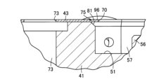
- a first example of the membrane protection structure 75 includes a chamfered portion 81 formed at a portion in contact with the cathode-side diaphragm 11 and/or the anode-side diaphragm 12 in the electrolytic bath 5 .
- the chamfered portion 81 is a portion that suppresses damage to the cathode-side diaphragm 11 and/or the anode-side diaphragm 12 due to physical contact with the cathode-side diaphragm 11 and/or the anode-side diaphragm 12. is.
- the chamfered portion 81 is the edge portion of the recessed portion 51 of the outer plate 41 and/or the corner portion (edge portion) of the branch portion 56 facing the cathode side diaphragm 11 and/or the anode side diaphragm 12. is formed in In addition, the chamfered portion 81 may be arbitrarily formed at a location that can come into contact with the cathode-side diaphragm 11 and/or the anode-side diaphragm 12 , such as the edge of the opening 61 of the partition 42 .
- the supply port 52 and the discharge port 53 suppress damage to the cathode-side diaphragm 11 and/or the anode-side diaphragm 12 due to the water pressure generated by the water flow in the direction crossing the cathode-side diaphragm 11 and/or the anode-side diaphragm 12. part.
- a fourth example of the membrane protection structure 75 includes three or more supporting parts capable of supporting the cathode side diaphragm 11 and/or the anode side diaphragm 12 .
- the branch portion 56 shown in FIGS. 1, 4 and 5 functions as a support portion.
- the branch portion 56 can support the cathode side diaphragm 11 and/or the anode side diaphragm 12 when water is supplied to the cathode chamber 6 and/or the anode chamber 7 and electrolysis is performed.
- the strength supporting the cathode side diaphragm 11 and/or the anode side diaphragm 12 is distributed, and the cathode side diaphragm 11 and/or the anode side diaphragm Reduce damage from physical contact with 12 prongs 56 .
- a supply pipe structure is a pipe structure that supplies water evenly or substantially evenly to the branched flow paths 57 between the branched portions 56 in the cathode chamber 6 and/or the anode chamber 7. 54.
- the supply pipe structure 54 includes an introduction pipe portion 83 that guides the water flowing in from the supply port 52 to the cathode chamber 6 and/or the anode chamber 7, and a plurality of branch pipes that branch the water from the introduction pipe portion 83 to the branch portions 56. a portion 84;
- the introduction pipe part 83 is arranged along the lateral direction of the outer plate 41 by bending in an L-shape from the supply port 52 at the upper part near one side of the cathode chamber 6 and/or the anode chamber 7 in the lateral direction.
- the introduction pipe part 83 has a constant or substantially constant flow area.
- the branch pipe portions 84 are arranged parallel or substantially parallel to each other along the vertical direction from the introduction pipe portion 83 .
- each branch pipe portion 84 communicates with the confluence portion 59 at a position facing each branch channel 57 .
- the branch pipe portion 84 has a channel area equal to or smaller than that of the introduction pipe portion 83 and is formed such that the channel area of the branch pipe portion 84 located farther from the supply port 52 becomes larger. Therefore, the supply pipe structure 54 distributes the water flowing in from the supply port 52 from the introduction pipe portion 83 to each branch pipe portion 84 evenly or substantially evenly in the branch flow paths 57 between the branch portions 56 . It is configured.
- the supply pipe structure 54 is a portion that suppresses damage to the cathode side diaphragm 11 and/or the anode side diaphragm 12 due to water pressure.
- a discharge pipe having a pipe structure for discharging electrolyzed water evenly or substantially evenly from the branch flow path 57 between the branch portions 56 in the cathode chamber 6 and/or the anode chamber 7 Includes structure 55 .
- the discharge pipe structure 55 includes a plurality of branch pipe portions 86 for discharging the electrolyzed water from the cathode chamber 6 and the anode chamber 7, and an outlet pipe portion 87 for merging the electrolyzed water from these branch pipe portions 86 and leading to the discharge port 53.
- the branch pipe portions 86 are arranged parallel or substantially parallel to each other along the vertical direction.
- a lower end portion of the branch pipe portion 86 communicates with the junction portion 58 at a position facing the branch flow path 57 .
- the branch pipe portion 86 has a channel area equal to or smaller than that of the lead-out pipe portion 87 and is formed such that the farther the position from the discharge port 53 , the larger the channel area.
- the lead-out pipe portion 87 is bent in an L-shape and arranged along the lateral direction of the outer plate 41, and communicates with the discharge port 53 at the upper part of the cathode chamber 6 and the anode chamber 7 near one side in the lateral direction. ing.
- Each branch pipe portion 86 is connected to the outlet pipe portion 87 .
- the discharge pipe structure 55 is designed to uniformly or substantially evenly discharge the electrolyzed water in the cathode chamber 6 and/or the anode chamber 7 from the branch flow path 57 between the branch portions 56 to the discharge port 53 via the confluence portion 59. is configured to
- the discharge pipe structure 55 is a portion that suppresses damage to the cathode side diaphragm 11 and/or the anode side diaphragm 12 due to water pressure.
- the supply pipe structure 64 includes an introduction pipe portion 90 that guides the saline solution flowing from the supply port 62 to the intermediate chamber 8, and a plurality of branch pipes that branch the salt solution from the introduction pipe portion 90 to positions corresponding to the branch portions 56. a portion 91; Since the structures of the introduction pipe portion 90 and the branch pipe portion 91 are the same as the structures of the introduction pipe portion 83 and the branch pipe portion 84 of the supply pipe structure 54, detailed description thereof will be omitted.
- the discharge pipe structure 65 includes a plurality of branch pipe portions 93 for discharging the saline solution from the intermediate chamber 8 and an outlet pipe portion 94 for merging the saline solution from these branch pipe portions 93 and leading to the discharge port 63.
- the structures of the branch pipe portion 93 and the lead-out pipe portion 94 are the same as the structures of the branch pipe portion 86 and the lead-out pipe portion 87 of the discharge pipe structure 55, so detailed description thereof will be omitted.
- the protrusion 96 is a portion that prevents the edge of the recess 51 from directly contacting the cathode side diaphragm 11 and/or the anode side diaphragm 12 (FIG. 1). That is, the projecting portion 96 is a portion that suppresses damage to the cathode side diaphragm 11 and/or the anode side diaphragm 12 (FIG. 1) due to physical contact with the cathode side diaphragm 11 and/or the anode side diaphragm 12 (FIG. 1). is.
- the protrusion 96 constitutes the edge of the hole 70 and protrudes into the cathode chamber 6 and/or the anode chamber 7 beyond the edge of the recess 51 by a predetermined distance, for example, 1 mm.
- the sealing member 44 shown in FIGS. 10 and 11 may also have a projection 97 on the edge of the hole 71 so as to similarly project from the edge of the opening 61 (FIG. 1).
- a ninth example of the membrane protection structure 75 includes a seal member 44 that holds the cathode-side diaphragm 11 and/or the anode-side diaphragm 12 at a position close to the cathode 13 and/or the anode 14 .
- the seal member 44 is formed by interposing the membrane supporting portion 72 between the cathode-side diaphragm 11 and/or the anode-side diaphragm 12 and the diaphragm 42, so that the cathode-side diaphragm 11 and/or the anode is
- the side diaphragm 12 is fixed at a position close to the cathode 13 and/or the anode 14, and the position of the cathode side diaphragm 11 and/or the anode side diaphragm 12 is stabilized during electrolysis, and the cathode side diaphragm 11 and/or the anode side is fixed.
- the sealing member 44 is a membrane protection member that suppresses damage to the cathode side diaphragm 11 and/or the anode side diaphragm 12 due to heat from the cathode 13 and/or the anode 14 during electrolysis.
- the generator 1 may be provided with one electrolytic bath 5 for the water supply source as shown in FIG.
- the electrolytic bath 5 may be provided in parallel.
- FIG. 12(b) by alternately arranging the outer plates 41 and the partition walls 42, a plurality of electrolytic cells 5 are stacked continuously.
- the outer plate 41 located between the partition walls 42 is formed with recesses 51 (FIG. 1) for forming chambers on both side surfaces.
- each electrolytic cell 5 is provided with a throttle so that the water flowing into the chambers 6, 7 and 8 and the water discharged from the chambers 6, 7 and 8 are made uniform or substantially uniform. is preferred.
- each electrolytic cell 5 is provided with an abnormality detection device that detects an abnormality such as leakage of saline solution caused by damage to the cathode-side diaphragm 11 and/or the anode-side diaphragm 12 based on the electrical properties of the electrolyzed water, such as the resistance value. By doing so, it is preferable to be able to discover which cathode side diaphragm 11 and/or which anode side diaphragm 12 of the electrolytic cell 5 has an abnormality.
- an abnormality such as leakage of saline solution caused by damage to the cathode-side diaphragm 11 and/or the anode-side diaphragm 12 based on the electrical properties of the electrolyzed water, such as the resistance value.
- the film protection structure 75 damage to the cathode-side diaphragm 11 and/or the anode-side diaphragm 12 can be suppressed. Therefore, the service life of the cathode-side diaphragm 11 and/or the anode-side diaphragm 12 can be extended, and the frequency of maintenance of the cathode-side diaphragm 11 and/or the anode-side diaphragm 12 of the generator 1 can be reduced to achieve low-cost electrolysis. Water can be produced.
- the membrane protection structure 75 protects the cathode-side diaphragm 11 and/or the anode-side diaphragm 12 from damage caused by at least one of physical contact, water pressure, and heat from the electrodes during electrolysis.
- the generating device 1 that supplies saline to the cathode chamber 6 and the anode chamber 7, supplies saline to the intermediate chamber 8, and generates and discharges electrolyzed water by electrolysis using the cathode side diaphragm 11 and the anode side diaphragm 12, the water is supplied.
- the cathode-side diaphragm 11 and/or the anode-side diaphragm 12 can be reliably protected against physical contact, excessive water pressure, and heat from the electrodes that may occur during discharge, electrolysis, and the like.
- the membrane protection structure 75 includes a chamfered portion 81 formed in a portion in contact with the cathode-side diaphragm 11 and/or the anode-side diaphragm 12 in the electrolytic cell 5 so that the cathode-side diaphragm 11 and/or the anode Damage to the cathode side diaphragm 11 and/or the anode side diaphragm 12 due to physical contact with the side diaphragm 12 can be suppressed.
- the membrane protection structure 75 includes a supply port 52 for supplying electrolyzed raw water to the cathode chamber 6 and/or the anode chamber 7 in a direction along the cathode side diaphragm 11 and/or the anode side diaphragm 12; and/or a discharge port 53 for discharging electrolyzed water from the chamber 7 in a direction along the cathode side diaphragm 11 and/or the anode side diaphragm 12. Water pressure (load) can be suppressed, and damage to the cathode side diaphragm 11 and/or the anode side diaphragm 12 can be suppressed.
- the outer plate 41 and the partition wall 42 can be alternately stacked in the thickness direction.
- a plurality of electrolytic cells 5 can be compactly constructed by alternately stacking a large number of outer plates 41 and partition walls 42 .
- the membrane protection structure 75 includes three or more branches 56 formed in the cathode chamber 6 and/or the anode chamber 7 and capable of supporting the cathode-side diaphragm 11 and/or the anode-side diaphragm 12. Narrowing the space between 56 (branch flow path 57) and forming the branch portion 56 itself to be relatively thin to support the cathode side diaphragm 11 and/or the anode side diaphragm 12 with high strength by the branch portion 56, By distributing the load on the cathode side diaphragm 11 and/or the anode side diaphragm 12, damage to the cathode side diaphragm 11 and/or the anode side diaphragm 12 due to water pressure or the like can be suppressed.
- the branch portions 56 By forming the branch portions 56 in the shape of ribs parallel to each other, the cathode-side diaphragm 11 and/or the anode-side diaphragm 12 are effectively supported, and the water flowing into the cathode chamber 6 and/or the anode chamber 7 and the cathode can be effectively supported.
- the electrolyzed water discharged from the chamber 6 and/or the anode chamber 7 can be guided by the branch portion 56 along the cathode-side diaphragm 11 and/or the anode-side diaphragm 12, respectively, and flow efficiently.
- the membrane protection structure 75 includes piping structures such as a supply piping structure 54 and a discharge piping structure 55 for evenly supplying water between the branches 56 in the cathode chamber 6 and/or the anode chamber 7, thereby In this way, it is possible to suppress unevenness of the water pressure to the cathode side diaphragm 11 and/or the anode side diaphragm 12 at , thereby further suppressing damage to the cathode side diaphragm 11 and/or the anode side diaphragm 12 .
- piping structures such as a supply piping structure 54 and a discharge piping structure 55 for evenly supplying water between the branches 56 in the cathode chamber 6 and/or the anode chamber 7, thereby In this way, it is possible to suppress unevenness of the water pressure to the cathode side diaphragm 11 and/or the anode side diaphragm 12 at , thereby further suppressing damage to the cathode side diaphragm 11 and/or the ano
- branching portions 56 by setting three or more branching portions 56, the space between the branching portions 56, 56 (branching flow path 57) is narrowed, but by dispersing water uniformly or substantially uniformly in these, Water can easily pass through, and treatment performance can be ensured.
- the membrane protection structure 75 is a projecting portion formed by projecting from the sealing member 43 that watertightly closes the gap between the outer plate 41 and the partition wall 42 beyond the edge of the recess 51 into the cathode chamber 6 and/or the anode chamber 7 .
- the membrane protection structure 75 is a projecting portion formed by projecting from the sealing member 43 that watertightly closes the gap between the outer plate 41 and the partition wall 42 beyond the edge of the recess 51 into the cathode chamber 6 and/or the anode chamber 7 .
- the purification capacity of electrolyzed water can be increased to about 5 to 10 L/min.
- the membrane protection structure 75 includes a sealing member 44 which is a sheet-like membrane protection member formed of fibers and fixing the position of the cathode side diaphragm 11 and/or the anode side diaphragm 12, the cathode 13 during electrolysis is And/or burning or damage to the cathode-side diaphragm 11 and/or the anode-side diaphragm 12 due to heat from the anode 14 can be suppressed.
- a sealing member 44 which is a sheet-like membrane protection member formed of fibers and fixing the position of the cathode side diaphragm 11 and/or the anode side diaphragm 12, the cathode 13 during electrolysis is And/or burning or damage to the cathode-side diaphragm 11 and/or the anode-side diaphragm 12 due to heat from the anode 14 can be suppressed.
- the sealing member 44 is arranged between each of the membranes 11 and 12 and the partition wall 42.
- the present invention is not limited to this.
- the membrane supporting portion 72 is arranged between one of the membranes 11 and 12 and the partition wall 42, and the membrane supporting portion 72 is provided. Even if the portion 72 is arranged so as to be close to the other of the membranes 11 and 12 from the opening 61, it can similarly act as a membrane protecting member.
- the vertical relationship between the supply ports 52, 62 and the discharge ports 53, 63 may be reversed.
- the supply ports 52 and 62 may be arranged in the upper part and the discharge ports 53 and 63 may be arranged in the lower part.
Landscapes
- Chemical & Material Sciences (AREA)
- Organic Chemistry (AREA)
- Chemical Kinetics & Catalysis (AREA)
- Electrochemistry (AREA)
- Engineering & Computer Science (AREA)
- General Chemical & Material Sciences (AREA)
- Life Sciences & Earth Sciences (AREA)
- Hydrology & Water Resources (AREA)
- Environmental & Geological Engineering (AREA)
- Water Supply & Treatment (AREA)
- Materials Engineering (AREA)
- Metallurgy (AREA)
- Water Treatment By Electricity Or Magnetism (AREA)
- Electrolytic Production Of Non-Metals, Compounds, Apparatuses Therefor (AREA)
Abstract
Description
Na++e- → Na
Na+OH- → NaOH+e-
2Cl- → Cl2+2e-
Cl2+H2O ⇔ HClO+HCl
Claims (8)
- 給電される対をなす電極と、隔膜と、を用いて電解水を生成する生成装置であって、
前記隔膜を介して仕切られた複数の室を有する電解槽と、
前記隔膜の損傷を抑制する膜保護構造と、を備え、
前記電解槽は、
前記室を区画する凹部を備える対をなすカバー部材と、
前記室を区画する開口部を備え、前記電極及び前記隔膜を介して前記カバー部材間に挟み込まれる隔壁と、
前記カバー部材と前記隔壁との隙間を水密に閉塞するシール部材と、を有し、
前記膜保護構造は、前記シール部材から前記凹部の縁部または前記開口部の縁部を超えて前記室内に突出して形成された突出部を含む
ことを特徴とする生成装置。 - 膜保護構造は、電解槽にて隔膜と接触する部分に形成された面取り部を含む
ことを特徴とする請求項1記載の生成装置。 - 膜保護構造は、室に対して隔膜に沿う方向に水を供給する供給口と、前記室から前記隔膜に沿う方向に水を排出する排出口と、の少なくともいずれかを含む
ことを特徴とする請求項1または2記載の生成装置。 - 膜保護構造は、室内に形成され隔膜を支持可能な三つ以上の支持部を含む
ことを特徴とする請求項1ないし3いずれか一記載の生成装置。 - 支持部は、互いに平行なリブ状に形成されている
ことを特徴とする請求項4記載の生成装置。 - 膜保護構造は、室内の支持部間に均等に電解原水を供給する配管構造を含む
ことを特徴とする請求項5記載の生成装置。 - 膜保護構造は、繊維により形成され隔膜の位置を固定するシート状の膜保護部材を含む
ことを特徴とする請求項1ないし6いずれか一記載の生成装置。 - 電解槽は、給水源に対し並列に複数配置されている
ことを特徴とする請求項1ないし7いずれか一記載の生成装置。
Priority Applications (3)
| Application Number | Priority Date | Filing Date | Title |
|---|---|---|---|
| CN202280005606.7A CN117279865A (zh) | 2021-12-28 | 2022-10-27 | 生成装置 |
| KR1020237005113A KR20230106146A (ko) | 2021-12-28 | 2022-10-27 | 생성 장치 |
| US18/021,789 US20240059592A1 (en) | 2021-12-28 | 2022-10-27 | Producing device |
Applications Claiming Priority (2)
| Application Number | Priority Date | Filing Date | Title |
|---|---|---|---|
| JP2021214707A JP7169021B1 (ja) | 2021-12-28 | 2021-12-28 | 生成装置 |
| JP2021-214707 | 2021-12-28 |
Publications (1)
| Publication Number | Publication Date |
|---|---|
| WO2023127265A1 true WO2023127265A1 (ja) | 2023-07-06 |
Family
ID=83995298
Family Applications (1)
| Application Number | Title | Priority Date | Filing Date |
|---|---|---|---|
| PCT/JP2022/040134 WO2023127265A1 (ja) | 2021-12-28 | 2022-10-27 | 生成装置 |
Country Status (6)
| Country | Link |
|---|---|
| US (1) | US20240059592A1 (ja) |
| JP (3) | JP7169021B1 (ja) |
| KR (1) | KR20230106146A (ja) |
| CN (1) | CN117279865A (ja) |
| TW (1) | TWI841088B (ja) |
| WO (1) | WO2023127265A1 (ja) |
Families Citing this family (1)
| Publication number | Priority date | Publication date | Assignee | Title |
|---|---|---|---|---|
| JP2021186294A (ja) * | 2020-05-29 | 2021-12-13 | 株式会社三洋物産 | 遊技機 |
Citations (10)
| Publication number | Priority date | Publication date | Assignee | Title |
|---|---|---|---|---|
| JP2002224671A (ja) * | 2001-01-31 | 2002-08-13 | Matsushita Electric Works Ltd | 電解槽 |
| JP2004008983A (ja) * | 2002-06-10 | 2004-01-15 | Shimazaki Denki Kk | 電解水生成装置及び方法 |
| JP2006255684A (ja) * | 2005-02-17 | 2006-09-28 | Suga Test Instr Co Ltd | 純水装置 |
| JP2008196014A (ja) * | 2007-02-13 | 2008-08-28 | Midori Anzen Co Ltd | 電解槽 |
| JP2016016346A (ja) | 2014-07-07 | 2016-02-01 | 株式会社東芝 | 電解水生成装置 |
| JP2016016360A (ja) * | 2014-07-08 | 2016-02-01 | 株式会社東芝 | 電解水生成装置 |
| WO2016043109A1 (ja) * | 2014-09-19 | 2016-03-24 | 株式会社 東芝 | 電解装置および電極 |
| JP2017056376A (ja) * | 2015-09-14 | 2017-03-23 | 株式会社東芝 | 電解槽およびこれを備える電解水生成装置 |
| JP2018030042A (ja) * | 2015-01-14 | 2018-03-01 | 株式会社東芝 | 電解水生成装置 |
| JP2018030045A (ja) * | 2015-06-16 | 2018-03-01 | 株式会社東芝 | 電解水生成装置および電解水生成方法 |
Family Cites Families (4)
| Publication number | Priority date | Publication date | Assignee | Title |
|---|---|---|---|---|
| SE451855B (sv) * | 1983-06-17 | 1987-11-02 | Svenska Utvecklings Ab | Elektrodkammarenhet avsedd att anvendas i en elektrokemisk cell med poros genomstromningselektrod, elektrokemisk cell, forfarande for framstellning av den elektrokemiska cellen samt anvendning derav for rening av vatten |
| JP6578181B2 (ja) * | 2015-10-08 | 2019-09-18 | モレックス エルエルシー | 電解水の製造装置 |
| CN210736278U (zh) * | 2019-06-18 | 2020-06-12 | 湀可绿色科技有限公司 | 电解槽装置 |
| JP6713615B1 (ja) * | 2019-08-21 | 2020-06-24 | 株式会社テックコーポレーション | 電解槽 |
-
2021
- 2021-12-28 JP JP2021214707A patent/JP7169021B1/ja active Active
-
2022
- 2022-10-21 JP JP2022169189A patent/JP7418867B2/ja active Active
- 2022-10-27 US US18/021,789 patent/US20240059592A1/en active Pending
- 2022-10-27 KR KR1020237005113A patent/KR20230106146A/ko unknown
- 2022-10-27 WO PCT/JP2022/040134 patent/WO2023127265A1/ja active Application Filing
- 2022-10-27 CN CN202280005606.7A patent/CN117279865A/zh active Pending
- 2022-12-02 TW TW111146408A patent/TWI841088B/zh active
-
2023
- 2023-12-26 JP JP2023219427A patent/JP2024027150A/ja active Pending
Patent Citations (10)
| Publication number | Priority date | Publication date | Assignee | Title |
|---|---|---|---|---|
| JP2002224671A (ja) * | 2001-01-31 | 2002-08-13 | Matsushita Electric Works Ltd | 電解槽 |
| JP2004008983A (ja) * | 2002-06-10 | 2004-01-15 | Shimazaki Denki Kk | 電解水生成装置及び方法 |
| JP2006255684A (ja) * | 2005-02-17 | 2006-09-28 | Suga Test Instr Co Ltd | 純水装置 |
| JP2008196014A (ja) * | 2007-02-13 | 2008-08-28 | Midori Anzen Co Ltd | 電解槽 |
| JP2016016346A (ja) | 2014-07-07 | 2016-02-01 | 株式会社東芝 | 電解水生成装置 |
| JP2016016360A (ja) * | 2014-07-08 | 2016-02-01 | 株式会社東芝 | 電解水生成装置 |
| WO2016043109A1 (ja) * | 2014-09-19 | 2016-03-24 | 株式会社 東芝 | 電解装置および電極 |
| JP2018030042A (ja) * | 2015-01-14 | 2018-03-01 | 株式会社東芝 | 電解水生成装置 |
| JP2018030045A (ja) * | 2015-06-16 | 2018-03-01 | 株式会社東芝 | 電解水生成装置および電解水生成方法 |
| JP2017056376A (ja) * | 2015-09-14 | 2017-03-23 | 株式会社東芝 | 電解槽およびこれを備える電解水生成装置 |
Also Published As
| Publication number | Publication date |
|---|---|
| JP7169021B1 (ja) | 2022-11-10 |
| KR20230106146A (ko) | 2023-07-12 |
| JP2024027150A (ja) | 2024-02-29 |
| JP2023098139A (ja) | 2023-07-10 |
| TWI841088B (zh) | 2024-05-01 |
| TW202336281A (zh) | 2023-09-16 |
| US20240059592A1 (en) | 2024-02-22 |
| JP7418867B2 (ja) | 2024-01-22 |
| JP2023098610A (ja) | 2023-07-10 |
| CN117279865A (zh) | 2023-12-22 |
Similar Documents
| Publication | Publication Date | Title |
|---|---|---|
| US20200340129A1 (en) | Expanded ion-exchange membrane electrolysis cell | |
| JP2024027150A (ja) | 生成装置 | |
| JP6247590B2 (ja) | セル積層体および蓄電池 | |
| JP2017057482A (ja) | 電極体、電解装置 | |
| JP4594357B2 (ja) | 殺菌剤製造装置 | |
| JP2017056376A (ja) | 電解槽およびこれを備える電解水生成装置 | |
| JP3885027B2 (ja) | 電解槽 | |
| JP4302386B2 (ja) | 電解装置 | |
| JP2016016346A (ja) | 電解水生成装置 | |
| KR101937930B1 (ko) | 수소수 전해조 | |
| US11584667B2 (en) | Electrolysis vessel | |
| TW202430721A (zh) | 生成裝置 | |
| WO2016114364A1 (ja) | 電解水生成装置 | |
| TW202130859A (zh) | 電解液體生成裝置 | |
| JPH10309581A (ja) | イオン水生成装置の電解槽 | |
| JP5380327B2 (ja) | 有隔膜電解槽の電解槽構造 | |
| KR20160076859A (ko) | 전해모듈 | |
| JP6472521B2 (ja) | 電解セルおよびこの電解セルを備える電解水生成装置 | |
| JP3827647B2 (ja) | ガス拡散電極を備えたイオン交換膜電解槽 | |
| KR102408265B1 (ko) | 챔버 프레임 엘리먼트, 전해조 및 전기투석조 | |
| WO2023167134A1 (ja) | 電解槽 | |
| JP7261260B2 (ja) | 電解槽 | |
| JP6470774B2 (ja) | 電解槽 | |
| JP2017056448A (ja) | 電解水生成装置 | |
| KR970004140B1 (ko) | 복극식 전해조 |
Legal Events
| Date | Code | Title | Description |
|---|---|---|---|
| WWE | Wipo information: entry into national phase |
Ref document number: 202317009728 Country of ref document: IN |
|
| WWE | Wipo information: entry into national phase |
Ref document number: 202280005606.7 Country of ref document: CN Ref document number: 18021789 Country of ref document: US |
|
| 121 | Ep: the epo has been informed by wipo that ep was designated in this application |
Ref document number: 22851000 Country of ref document: EP Kind code of ref document: A1 |
|
| WWE | Wipo information: entry into national phase |
Ref document number: 2022851000 Country of ref document: EP |
|
| NENP | Non-entry into the national phase |
Ref country code: DE |
|
| ENP | Entry into the national phase |
Ref document number: 2022851000 Country of ref document: EP Effective date: 20240729 |