WO2023120687A1 - 二次電池 - Google Patents
二次電池 Download PDFInfo
- Publication number
- WO2023120687A1 WO2023120687A1 PCT/JP2022/047544 JP2022047544W WO2023120687A1 WO 2023120687 A1 WO2023120687 A1 WO 2023120687A1 JP 2022047544 W JP2022047544 W JP 2022047544W WO 2023120687 A1 WO2023120687 A1 WO 2023120687A1
- Authority
- WO
- WIPO (PCT)
- Prior art keywords
- secondary battery
- negative electrode
- heat
- positive electrode
- group
- Prior art date
Links
Images


Classifications
-
- H—ELECTRICITY
- H01—ELECTRIC ELEMENTS
- H01M—PROCESSES OR MEANS, e.g. BATTERIES, FOR THE DIRECT CONVERSION OF CHEMICAL ENERGY INTO ELECTRICAL ENERGY
- H01M10/00—Secondary cells; Manufacture thereof
- H01M10/05—Accumulators with non-aqueous electrolyte
- H01M10/052—Li-accumulators
-
- H—ELECTRICITY
- H01—ELECTRIC ELEMENTS
- H01M—PROCESSES OR MEANS, e.g. BATTERIES, FOR THE DIRECT CONVERSION OF CHEMICAL ENERGY INTO ELECTRICAL ENERGY
- H01M10/00—Secondary cells; Manufacture thereof
- H01M10/05—Accumulators with non-aqueous electrolyte
- H01M10/056—Accumulators with non-aqueous electrolyte characterised by the materials used as electrolytes, e.g. mixed inorganic/organic electrolytes
- H01M10/0564—Accumulators with non-aqueous electrolyte characterised by the materials used as electrolytes, e.g. mixed inorganic/organic electrolytes the electrolyte being constituted of organic materials only
- H01M10/0566—Liquid materials
- H01M10/0568—Liquid materials characterised by the solutes
-
- H—ELECTRICITY
- H01—ELECTRIC ELEMENTS
- H01M—PROCESSES OR MEANS, e.g. BATTERIES, FOR THE DIRECT CONVERSION OF CHEMICAL ENERGY INTO ELECTRICAL ENERGY
- H01M50/00—Constructional details or processes of manufacture of the non-active parts of electrochemical cells other than fuel cells, e.g. hybrid cells
- H01M50/40—Separators; Membranes; Diaphragms; Spacing elements inside cells
- H01M50/409—Separators, membranes or diaphragms characterised by the material
- H01M50/411—Organic material
- H01M50/414—Synthetic resins, e.g. thermoplastics or thermosetting resins
- H01M50/42—Acrylic resins
-
- H—ELECTRICITY
- H01—ELECTRIC ELEMENTS
- H01M—PROCESSES OR MEANS, e.g. BATTERIES, FOR THE DIRECT CONVERSION OF CHEMICAL ENERGY INTO ELECTRICAL ENERGY
- H01M50/00—Constructional details or processes of manufacture of the non-active parts of electrochemical cells other than fuel cells, e.g. hybrid cells
- H01M50/40—Separators; Membranes; Diaphragms; Spacing elements inside cells
- H01M50/409—Separators, membranes or diaphragms characterised by the material
- H01M50/411—Organic material
- H01M50/414—Synthetic resins, e.g. thermoplastics or thermosetting resins
- H01M50/423—Polyamide resins
-
- H—ELECTRICITY
- H01—ELECTRIC ELEMENTS
- H01M—PROCESSES OR MEANS, e.g. BATTERIES, FOR THE DIRECT CONVERSION OF CHEMICAL ENERGY INTO ELECTRICAL ENERGY
- H01M50/00—Constructional details or processes of manufacture of the non-active parts of electrochemical cells other than fuel cells, e.g. hybrid cells
- H01M50/40—Separators; Membranes; Diaphragms; Spacing elements inside cells
- H01M50/409—Separators, membranes or diaphragms characterised by the material
- H01M50/411—Organic material
- H01M50/414—Synthetic resins, e.g. thermoplastics or thermosetting resins
- H01M50/426—Fluorocarbon polymers
-
- H—ELECTRICITY
- H01—ELECTRIC ELEMENTS
- H01M—PROCESSES OR MEANS, e.g. BATTERIES, FOR THE DIRECT CONVERSION OF CHEMICAL ENERGY INTO ELECTRICAL ENERGY
- H01M50/00—Constructional details or processes of manufacture of the non-active parts of electrochemical cells other than fuel cells, e.g. hybrid cells
- H01M50/40—Separators; Membranes; Diaphragms; Spacing elements inside cells
- H01M50/409—Separators, membranes or diaphragms characterised by the material
- H01M50/431—Inorganic material
- H01M50/434—Ceramics
-
- H—ELECTRICITY
- H01—ELECTRIC ELEMENTS
- H01M—PROCESSES OR MEANS, e.g. BATTERIES, FOR THE DIRECT CONVERSION OF CHEMICAL ENERGY INTO ELECTRICAL ENERGY
- H01M50/00—Constructional details or processes of manufacture of the non-active parts of electrochemical cells other than fuel cells, e.g. hybrid cells
- H01M50/40—Separators; Membranes; Diaphragms; Spacing elements inside cells
- H01M50/409—Separators, membranes or diaphragms characterised by the material
- H01M50/446—Composite material consisting of a mixture of organic and inorganic materials
-
- H—ELECTRICITY
- H01—ELECTRIC ELEMENTS
- H01M—PROCESSES OR MEANS, e.g. BATTERIES, FOR THE DIRECT CONVERSION OF CHEMICAL ENERGY INTO ELECTRICAL ENERGY
- H01M50/00—Constructional details or processes of manufacture of the non-active parts of electrochemical cells other than fuel cells, e.g. hybrid cells
- H01M50/40—Separators; Membranes; Diaphragms; Spacing elements inside cells
- H01M50/409—Separators, membranes or diaphragms characterised by the material
- H01M50/449—Separators, membranes or diaphragms characterised by the material having a layered structure
- H01M50/451—Separators, membranes or diaphragms characterised by the material having a layered structure comprising layers of only organic material and layers containing inorganic material
-
- Y—GENERAL TAGGING OF NEW TECHNOLOGICAL DEVELOPMENTS; GENERAL TAGGING OF CROSS-SECTIONAL TECHNOLOGIES SPANNING OVER SEVERAL SECTIONS OF THE IPC; TECHNICAL SUBJECTS COVERED BY FORMER USPC CROSS-REFERENCE ART COLLECTIONS [XRACs] AND DIGESTS
- Y02—TECHNOLOGIES OR APPLICATIONS FOR MITIGATION OR ADAPTATION AGAINST CLIMATE CHANGE
- Y02E—REDUCTION OF GREENHOUSE GAS [GHG] EMISSIONS, RELATED TO ENERGY GENERATION, TRANSMISSION OR DISTRIBUTION
- Y02E60/00—Enabling technologies; Technologies with a potential or indirect contribution to GHG emissions mitigation
- Y02E60/10—Energy storage using batteries
Definitions
- This technology relates to secondary batteries.
- the secondary battery includes a positive electrode, a negative electrode, and an electrolytic solution, and various studies have been made on the configuration of the secondary battery.
- Faiz Ahmed et al. ⁇ Novel divalent organo-lithium salts with high electrochemical and thermal stability for aqueous rechargeable Li-Ion batteries'', Electrochimica Acta, 298, 2019, 709-716 Faiz Ahmed et al., ⁇ Highly conductive divalent fluorosulfonyl imide based electrolytes improving Li-ion battery performance: Additive potentiating'', Journal of Power Sources, 455, 2020, 227980
- a secondary battery that can obtain excellent battery characteristics is desired.
- a secondary battery includes a positive electrode including a positive electrode active material layer, a negative electrode including a negative electrode active material layer, a separator and a heat-resistant layer disposed between the positive electrode and the negative electrode, and an electrolyte salt. and an electrolytic solution comprising:
- the heat-resistant layer is arranged at least in a region where the positive electrode active material layer and the negative electrode active material layer face each other, and has a melting point or decomposition temperature higher than that of the separator.
- the electrolyte salt contains an imide anion, and the imide anion is a first imide anion represented by formula (1), a second imide anion represented by formula (2), and a third imide anion represented by formula (3). At least one of the imide anion and the quaternary imide anion represented by formula (4) is included.
- Each of R3 and R4 is either a fluorine group or a fluorinated alkyl group.
- Each of X1, X2, X3 and X4 is one of a carbonyl group, a sulfinyl group and a sulfonyl group.
- R5 is a fluorinated alkylene group.
- Each of Y1, Y2 and Y3 is a carbonyl group, a sulfinyl group and a sulfonyl group.
- R6 and R7 is either a fluorine group or a fluorinated alkyl group.
- R8 is any one of an alkylene group, a phenylene group, a fluorinated alkylene group and a fluorinated phenylene group.
- Z1 , Z2, Z3 and Z4 are each a carbonyl group, a sulfinyl group and a sulfonyl group.
- the separator and the heat-resistant layer are arranged between the positive electrode and the negative electrode, and in the heat-resistant layer, at least the positive electrode active material layer and the negative electrode active material layer face each other. region and has a melting point or decomposition temperature higher than that of the separator, and the electrolyte salt of the electrolytic solution has imide anions such as primary imide anion, secondary imide anion, tertiary imide anion and Since at least one of the quaternary imide anions is included, excellent battery characteristics can be obtained.
- FIG. 2 is a cross-sectional view showing the configuration of part of the battery element shown in FIG. 1.
- FIG. FIG. 2 is a cross-sectional view showing the overall configuration of the battery element shown in FIG. 1; 4 is a cross-sectional view showing the configuration of a battery element in Modification 1.
- FIG. FIG. 10 is a cross-sectional view showing the configuration of a battery element in Modification 2;
- FIG. 11 is a cross-sectional view showing the configuration of a battery element in Modification 3;
- FIG. 11 is a cross-sectional view showing the configuration of a battery element in modification 4;
- FIG. 11 is a cross-sectional view showing the configuration of a battery element in modification 5;
- FIG. 11 is a cross-sectional view showing the configuration of a battery element in modification 6;
- FIG. 11 is a cross-sectional view showing the configuration of a battery element in modification 7;
- FIG. 11 is a cross-sectional view showing the configuration of a battery element in modification 8;
- FIG. 3 is a block diagram showing the configuration of an application example of a secondary battery;
- the secondary battery described here is a secondary battery in which battery capacity is obtained by utilizing the absorption and release of electrode reactants, and is equipped with an electrolyte along with a positive electrode and a negative electrode.
- the charge capacity of the negative electrode is larger than the discharge capacity of the positive electrode. That is, the electrochemical capacity per unit area of the negative electrode is set to be larger than the electrochemical capacity per unit area of the positive electrode. This is to prevent electrode reactants from depositing on the surface of the negative electrode during charging.
- the type of electrode reactant is not particularly limited, but specifically light metals such as alkali metals and alkaline earth metals.
- alkali metals are lithium, sodium and potassium, and examples of alkaline earth metals are beryllium, magnesium and calcium.
- the type of electrode reactant may be other light metals such as aluminum.
- lithium ion secondary battery A secondary battery whose battery capacity is obtained by utilizing the absorption and release of lithium is a so-called lithium ion secondary battery.
- lithium ion secondary battery lithium is intercalated and deintercalated in an ionic state.
- FIG. 1 shows a perspective configuration of a secondary battery.
- FIG. 2 shows a cross-sectional structure of part of the battery element 20 shown in FIG.
- FIG. 3 shows the overall cross-sectional structure of the battery element 20 shown in FIG.
- FIG. 1 shows a state in which the exterior film 10 and the battery element 20 are separated from each other, and the cross section of the battery element 20 along the XZ plane is indicated by a broken line.
- FIG. 3 shows a state in which the positive electrode 21, the negative electrode 22, the separator 23, and the heat-resistant layer 24 are separated from each other before winding.
- This secondary battery as shown in FIGS. 1 to 3, includes an exterior film 10, a battery element 20, a positive electrode lead 31, a negative electrode lead 32, and sealing films 41 and .
- the secondary battery described here is a laminated film type secondary battery using a flexible or pliable exterior film 10 .
- the upper side in each of FIGS. 1 to 3 is the upper side of the secondary battery
- the lower side in each of FIGS. 1 to 3 is the lower side of the secondary battery
- the exterior film 10 is an exterior member that houses the battery element 20, and has a sealed bag-like structure with the battery element 20 housed therein.
- the exterior film 10 accommodates the electrolytic solution together with the positive electrode 21 and the negative electrode 22 .
- the exterior film 10 is a single film-like member and is folded in the folding direction F.
- the exterior film 10 is provided with a recessed portion 10U (so-called deep drawn portion) for housing the battery element 20 .
- the exterior film 10 is a three-layer laminate film in which a fusion layer, a metal layer, and a surface protective layer are laminated in this order from the inside. Outer peripheral edge portions of the fusion layer are fused together.
- the fusible layer contains a polymer compound such as polypropylene.
- the metal layer contains a metal material such as aluminum.
- the surface protective layer contains a polymer compound such as nylon.
- the configuration (number of layers) of the exterior film 10 is not particularly limited, and may be one layer, two layers, or four layers or more.
- the sealing film 41 is inserted between the exterior film 10 and the positive electrode lead 31
- the sealing film 42 is inserted between the exterior film 10 and the negative electrode lead 32 .
- one or both of the sealing films 41 and 42 may be omitted.
- the sealing film 41 is a sealing member that prevents external air from entering the exterior film 10 . Further, the sealing film 41 contains a polymer compound such as polyolefin having adhesiveness to the positive electrode lead 31, and a specific example of the polymer compound is polypropylene.
- the structure of the sealing film 42 is the same as the structure of the sealing film 41 except that it is a sealing member having adhesion to the negative electrode lead 32 . That is, the sealing film 42 contains a polymer compound such as polyolefin that has adhesiveness to the negative electrode lead 32 .
- the battery element 20 is a power generation element including a positive electrode 21, a negative electrode 22, a separator 23, a heat-resistant layer 24, and an electrolytic solution (not shown), as shown in FIGS. 10 is housed inside.
- This battery element 20 is a so-called wound electrode assembly. That is, the positive electrode 21 and the negative electrode 22 are laminated with each other with the separator 23 and the heat-resistant layer 24 interposed therebetween, and are wound around the winding axis P while facing each other with the separator 23 and the heat-resistant layer 24 interposed therebetween.
- the winding axis P is a virtual axis extending in the Y-axis direction.
- the three-dimensional shape of the battery element 20 is not particularly limited.
- the shape of the cross section of the battery element 20 intersecting the winding axis P (the cross section along the XZ plane) is determined by the long axis J1 and the short axis J2.
- the long axis J1 is a virtual axis extending in the X-axis direction and having a length greater than that of the short axis J2.
- the minor axis J2 is a virtual axis that extends in the Z-axis direction that intersects with the X-axis direction and that has a length smaller than that of the major axis J1.
- the cross-sectional shape of the battery element 20 is a flat, substantially elliptical shape.
- the positive electrode 21 includes a positive electrode current collector 21A and a positive electrode active material layer 21B, as shown in FIG.
- the positive electrode current collector 21A has a pair of surfaces on which the positive electrode active material layer 21B is provided.
- the positive electrode current collector 21A contains a conductive material such as a metal material, and a specific example of the conductive material is aluminum.
- the positive electrode active material layer 21B contains one or more of positive electrode active materials that occlude and release lithium. However, the positive electrode active material layer 21B may further contain one or more of other materials such as a positive electrode binder and a positive electrode conductor.
- the positive electrode active material layer 21B is provided on both sides of the positive electrode current collector 21A.
- the positive electrode active material layer 21B may be provided only on one side of the positive electrode current collector 21A on the side where the positive electrode 21 faces the negative electrode 22 .
- a method for forming the positive electrode active material layer 21B is not particularly limited, but a specific example is a coating method.
- the type of positive electrode active material is not particularly limited, it is specifically a lithium-containing compound.
- This lithium-containing compound is a compound containing lithium and one or more transition metal elements as constituent elements, and may further contain one or more other elements as constituent elements.
- the type of the other element is not particularly limited as long as it is an element other than lithium and transition metal elements, but specifically, it is an element belonging to Groups 2 to 15 in the long period periodic table.
- the type of lithium-containing compound is not particularly limited, but specific examples include oxides, phosphoric acid compounds, silicic acid compounds and boric acid compounds.
- oxides are LiNiO2 , LiCoO2 , LiCo0.98Al0.01Mg0.01O2 , LiNi0.5Co0.2Mn0.3O2 , LiNi0.8Co0.15Al0.05O2 , LiNi0.33Co0.33Mn0.33 . O2 , Li 1.2Mn0.52Co0.175Ni0.1O2 , Li1.15 ( Mn0.65Ni0.22Co0.13 ) O2 and LiMn2O4 .
- _ _ Specific examples of phosphoric acid compounds include LiFePO4 , LiMnPO4 , LiFe0.5Mn0.5PO4 and LiFe0.3Mn0.7PO4 .
- the positive electrode binder contains one or more of synthetic rubber and polymer compounds.
- synthetic rubbers include styrene-butadiene rubber, fluororubber, and ethylene propylene diene.
- polymer compounds include polyvinylidene fluoride, polyimide and carboxymethylcellulose.
- the positive electrode conductive agent contains one or more of conductive materials such as carbon materials.
- conductive materials such as carbon materials.
- Specific examples of carbon materials include graphite, carbon black, acetylene black and ketjen black.
- the conductive material may be a metal material, a polymer compound, or the like.
- the negative electrode 22 includes a negative electrode current collector 22A and a negative electrode active material layer 22B, as shown in FIG.
- the negative electrode current collector 22A has a pair of surfaces on which the negative electrode active material layer 22B is provided.
- the negative electrode current collector 22A contains a conductive material such as a metal material, and a specific example of the metal material is copper.
- the negative electrode active material layer 22B contains one or more of negative electrode active materials that occlude and release lithium. However, the negative electrode active material layer 22B may further contain one or more of other materials such as a negative electrode binder and a negative electrode conductor.
- the negative electrode active material layer 22B is provided on both sides of the negative electrode current collector 22A.
- the negative electrode active material layer 22B may be provided only on one side of the negative electrode current collector 22A on the side where the negative electrode 22 faces the positive electrode 21 .
- the method of forming the negative electrode active material layer 22B is not particularly limited, but specifically, any one of a coating method, a vapor phase method, a liquid phase method, a thermal spraying method, a firing method (sintering method), or the like, or Two or more types.
- the type of negative electrode active material is not particularly limited, but specific examples include carbon materials and metal-based materials. This is because a high energy density can be obtained.
- the negative electrode active material may contain either one of the carbon material and the metal-based material, or may contain both of them.
- carbon materials include graphitizable carbon, non-graphitizable carbon, and graphite.
- This graphite may be natural graphite, artificial graphite, or both.
- a metallic material is a material containing as constituent elements one or more of metallic elements and semi-metallic elements capable of forming an alloy with lithium. , silicon and tin.
- This metallic material may be a single substance, an alloy, a compound, a mixture of two or more of them, or a material containing two or more of these phases.
- Specific examples of metallic materials include TiSi 2 and SiO x (0 ⁇ x ⁇ 2 or 0.2 ⁇ x ⁇ 1.4).
- each of the negative electrode binder and the negative electrode conductive agent is the same as those of the positive electrode binder and the positive electrode conductive agent.
- the positive electrode active material layer 21B is provided on part of the surface of the positive electrode current collector 21A
- the negative electrode active material layer 22B is provided on the surface of the negative electrode current collector 22A. It is provided on part of the surface.
- the positive electrode active material layer 21B is formed on the surface of the positive electrode current collector 21A in the longitudinal direction. located in the central region of the Thereby, the central region of the surface of the positive electrode current collector 21A is covered with the positive electrode active material layer 21B.
- the inner end region of the winding is exposed without being covered with the positive electrode active material layer 21B.
- the end region on the outer side of the winding is exposed without being covered with the positive electrode active material layer 21B.
- the negative electrode active material layer 22B is formed in the central region of the surface of the negative electrode current collector 22A in the longitudinal direction. are placed in As a result, the central region of the surface of the negative electrode current collector 22A is covered with the negative electrode active material layer 22B.
- the inner end region of the surface of the negative electrode current collector 22A is exposed without being covered with the negative electrode active material layer 22B. The end region on the outer side of the winding is not covered with the negative electrode active material layer 22B and is exposed.
- the arrangement range of the negative electrode active material layer 22B in the longitudinal direction is expanded to the winding inner side than the arrangement range of the positive electrode active material layer 21B in the longitudinal direction. It extends to the winding outside from the arrangement range.
- the portion arranged in the facing region R participates in charging and discharging, but the portion not arranged in the facing region R hardly participates in charging and discharging.
- the facing region R and the non-facing region exist in the positive electrode 21 and the negative electrode 22 because the charge/discharge This is to prevent lithium metal from unintentionally depositing on the surface of the negative electrode current collector 22A while securing a possible region (facing region R).
- the separator 23 is an insulating porous film placed between the positive electrode 21 and the negative electrode 22, as shown in FIGS. It allows lithium ions to pass through while preventing it.
- This separator 23 contains a polymer compound such as polyethylene.
- the electrolytic solution is a liquid electrolyte. This electrolytic solution is impregnated into each of the positive electrode 21, the negative electrode 22, the separator 23 and the heat-resistant layer 24, and contains an electrolyte salt. More specifically, the electrolytic solution contains an electrolyte salt and a solvent that disperses (ionizes) the electrolyte salt.
- Electrolyte salts are compounds that ionize in a solvent and contain anions and cations.
- Anions include imide anions.
- the imide anion includes the first imide anion represented by formula (1), the second imide anion represented by formula (2), the third imide anion represented by formula (3), and the formula ( 4) contains one or more of the quaternary imide anions represented by That is, the electrolyte salt contains an imide anion as an anion.
- the number of types of the first imide anions may be one, or two or more.
- the fact that the number of types may be one or two or more is the same for each of the second imide anion, the tertiary imide anion, and the quaternary imide anion.
- Each of R1 and R2 is either a fluorine group or a fluorinated alkyl group.
- Each of W1, W2 and W3 is one of a carbonyl group, a sulfinyl group and a sulfonyl group.
- Each of R3 and R4 is either a fluorine group or a fluorinated alkyl group.
- Each of X1, X2, X3 and X4 is one of a carbonyl group, a sulfinyl group and a sulfonyl group.
- R5 is a fluorinated alkylene group.
- Each of Y1, Y2 and Y3 is a carbonyl group, a sulfinyl group and a sulfonyl group.
- R6 and R7 is either a fluorine group or a fluorinated alkyl group.
- R8 is any one of an alkylene group, a phenylene group, a fluorinated alkylene group and a fluorinated phenylene group.
- Z1 , Z2, Z3 and Z4 are each a carbonyl group, a sulfinyl group and a sulfonyl group.
- the anion contains the imide anion is as explained below.
- a high-quality film derived from the electrolyte salt is formed on each surface of the positive electrode 21 and the negative electrode 22 . This suppresses the decomposition reaction of the electrolytic solution (particularly the solvent) caused by the reaction with each of the positive electrode 21 and the negative electrode 22 .
- the coating film described above the movement speed of lithium ions near the surfaces of the positive electrode 21 and the negative electrode 22 is improved.
- the movement speed of lithium ions is improved even in the electrolyte.
- the first imide anion is a chain anion (divalent negative ion) containing two nitrogen atoms (N) and three functional groups (W1 to W3), as shown in formula (1). .
- Each of R1 and R2 is not particularly limited as long as it is either a fluorine group (-F) or a fluorinated alkyl group. That is, each of R1 and R2 may be the same group or different groups. Accordingly, each of R1 and R2 is not a hydrogen group (--H), an alkyl group, or the like.
- a fluorinated alkyl group is a group in which one or more hydrogen groups (-H) in an alkyl group are substituted with a fluorine group.
- the fluorinated alkyl group may be linear or branched with one or more side chains.
- the number of carbon atoms in the fluorinated alkyl group is not particularly limited, it is specifically 1-10. This is because the solubility and ionization properties of the electrolyte salt containing the primary imide anion are improved.
- fluorinated alkyl groups include perfluoromethyl groups (--CF 3 ) and perfluoroethyl groups (--C 2 F 5 ).
- Each of W1 to W3 is not particularly limited as long as it is any one of a carbonyl group, a sulfinyl group and a sulfonyl group. That is, each of W1 to W3 may be the same group, or may be a different group. Of course, any two of W1 to W3 may be the same group.
- the second imide anion is a chain anion (trivalent negative ion) containing three nitrogen atoms and four functional groups (X1 to X4), as shown in formula (2).
- Each of X1 to X4 is not particularly limited as long as it is any one of a carbonyl group, a sulfinyl group and a sulfonyl group. That is, each of X1 to X4 may be the same group or different groups. Of course, any two of X1 to X4 may be the same group, or any three of X1 to X4 may be the same group.
- the third imide anion is a cyclic anion (divalent negative ions).
- the fluorinated alkylene group for R5 is an alkylene group in which one or more hydrogen groups have been substituted with fluorine groups.
- the fluorinated alkylene group may be linear or branched having one or more side chains.
- the number of carbon atoms in the fluorinated alkylene group is not particularly limited, it is specifically 1-10. This is because the solubility and ionization properties of the electrolyte salt containing the tertiary imide anion are improved.
- fluorinated alkylene groups include perfluoromethylene groups (--CF 2 --) and perfluoroethylene groups (--C 2 F 4 --).
- Each of Y1 to Y3 is not particularly limited as long as it is any one of a carbonyl group, a sulfinyl group and a sulfonyl group. That is, each of Y1 to Y3 may be the same group or different groups. Of course, any two of Y1 to Y3 may be the same group.
- the fourth imide anion is a chain anion containing two nitrogen atoms (N), four functional groups (Z1 to Z4) and one connecting group (R8), as shown in formula (4). (divalent negative ions).
- R8 is not particularly limited as long as it is any one of an alkylene group, a phenylene group, a fluorinated alkylene group and a fluorinated phenylene group.
- Alkylene groups can be linear or branched with one or more side chains. Although the number of carbon atoms in the alkylene group is not particularly limited, it is specifically 1-10. This is because the solubility and ionization properties of the electrolyte salt containing the quaternary imide anion are improved. Specific examples of alkylene groups include a methylene group (--CH 2 --), an ethylene group (--C 2 H 4 --) and a propylene group (--C 3 H 6 --).
- the details regarding the fluorinated alkylene group for R8 are the same as the details regarding the fluorinated alkylene group for R5.
- a fluorinated phenylene group is a group in which one or more hydrogen groups in a phenylene group have been replaced with fluorine groups.
- a specific example of the fluorinated phenylene group is a monofluorophenylene group (--C 6 H 3 F--).
- Each of Z1 to Z4 is not particularly limited as long as it is any one of a carbonyl group, a sulfinyl group and a sulfonyl group. That is, each of Z1 to Z4 may be the same group or different groups. Of course, any two of Z1 to Z4 may be the same groups, or any three of Z1 to Z4 may be the same groups.
- first imide anion examples include anions represented by formulas (1-1) to (1-30).
- second imide anion examples include anions represented by formulas (2-1) to (2-22).
- third imide anion examples include anions represented by formulas (3-1) to (3-15).
- quaternary imide anion examples include anions represented by formulas (4-1) to (4-65).
- the type of cation is not particularly limited. Specifically, the cation contains one or more of light metal ions. That is, the electrolyte salt contains light metal ions as cations. This is because a high voltage can be obtained.
- the types of light metal ions are not particularly limited, but specific examples include alkali metal ions and alkaline earth metal ions. Specific examples of alkali metal ions include sodium ions and potassium ions. Specific examples of alkaline earth metal ions include beryllium ions, magnesium ions and calcium ions. Alternatively, light metal ions may be aluminum ions.
- the light metal ions preferably contain lithium ions. This is because a sufficiently high voltage can be obtained.
- the content of the electrolyte salt in the electrolytic solution is not particularly limited and can be set arbitrarily. Among them, the content of the electrolyte salt is preferably 0.2 mol/kg to 2 mol/kg. This is because high ionic conductivity can be obtained.
- the "content of the electrolyte salt” described here is the content of the electrolyte salt relative to the solvent.
- the electrolyte solution is recovered by disassembling the secondary battery, and then the electrolyte solution is analyzed using Inductively Coupled Plasma (ICP) emission spectrometry. analyse. Since the weight of the solvent and the weight of the electrolyte salt are thus specified, the content of the electrolyte salt is calculated.
- ICP Inductively Coupled Plasma
- the solvent contains one or more of non-aqueous solvents (organic solvents), and the electrolytic solution containing the non-aqueous solvent is a so-called non-aqueous electrolytic solution.
- non-aqueous solvents include esters, ethers, and the like, and more specifically, carbonate compounds, carboxylic acid ester compounds, lactone compounds, and the like.
- the carbonate compounds include cyclic carbonates and chain carbonates.
- cyclic carbonates include ethylene carbonate and propylene carbonate.
- chain carbonates include dimethyl carbonate, diethyl carbonate and ethylmethyl carbonate.
- the carboxylic acid ester compound is a chain carboxylic acid ester or the like.
- chain carboxylic acid esters include methyl acetate, ethyl acetate, methyl propionate, ethyl propionate, propyl propionate, ethyl trimethylacetate, methyl butyrate and ethyl butyrate.
- Lactone-based compounds include lactones. Specific examples of lactones include ⁇ -butyrolactone and ⁇ -valerolactone.
- Ethers may be 1,2-dimethoxyethane, tetrahydrofuran, 1,3-dioxolane, 1,4-dioxane, and the like.
- the electrolytic solution may further contain one or more of other electrolytic salts. This is because the moving speed of lithium ions is further improved in the vicinity of the respective surfaces of the positive electrode 21 and the negative electrode 22, and the moving speed of lithium ions is further improved in the electrolyte solution.
- the content of the other electrolyte salt in the electrolytic solution is not particularly limited and can be set arbitrarily.
- electrolyte salt is not particularly limited, it is specifically a light metal salt such as lithium salt. However, the electrolyte salt described above is excluded from the lithium salt described here.
- lithium salts include lithium hexafluorophosphate (LiPF 6 ), lithium tetrafluoroborate (LiBF 4 ), lithium trifluoromethanesulfonate (LiCF 3 SO 3 ), lithium bis(fluorosulfonyl)imide (LiN ( FSO2 ) 2 ), bis(trifluoromethanesulfonyl )imidolithium (LiN(CF3SO2)2), lithium tris(trifluoromethanesulfonyl)methide (LiC(CF3SO2)3 ) , bis ( oxalato )boron lithium oxide (LiB( C2O4 ) 2 ), lithium difluorooxalatoborate ( LiBF2 ( C2O4 )) , lithium difluorodi(oxalato)borate ( LiPF2 ( C2O4 ) 2 ) and tetra Lithium fluorooxalate phosphate
- the other electrolyte salt is any one of lithium hexafluorophosphate, lithium tetrafluoroborate, lithium bis(fluorosulfonyl)imide, lithium bis(oxalato)borate and lithium difluorophosphate, or It is preferable that two or more types are included. This is because the moving speed of lithium ions is sufficiently improved in the vicinity of the respective surfaces of the positive electrode 21 and the negative electrode 22, and the moving speed of lithium ions is also sufficiently improved in the electrolyte solution.
- the electrolytic solution may further contain one or more of additives. This is because a coating film derived from the additive is formed on each surface of the positive electrode 21 and the negative electrode 22 during charging and discharging of the secondary battery, so that the decomposition reaction of the electrolytic solution is suppressed.
- the content of the additive in the electrolytic solution is not particularly limited, and can be set arbitrarily.
- the types of additives are not particularly limited, but specific examples include unsaturated cyclic carbonates, fluorinated cyclic carbonates, sulfonic acid esters, dicarboxylic acid anhydrides, disulfonic acid anhydrides, sulfuric acid esters, nitrile compounds and isocyanate compounds. and so on.
- An unsaturated cyclic carbonate is a cyclic carbonate containing an unsaturated carbon bond (carbon-carbon double bond).
- the number of unsaturated carbon bonds is not particularly limited, and may be one or two or more.
- Specific examples of unsaturated cyclic carbonates include vinylene carbonate, vinylethylene carbonate and methyleneethylene carbonate.
- a fluorinated cyclic carbonate is a cyclic carbonate containing fluorine as a constituent element. That is, the fluorinated cyclic carbonate is a compound in which one or more hydrogen groups in the cyclic carbonate are substituted with fluorine groups.
- Specific examples of fluorinated cyclic carbonates include ethylene monofluorocarbonate and ethylene difluorocarbonate.
- Sulfonic acid esters include cyclic monosulfonic acid esters, cyclic disulfonic acid esters, chain monosulfonic acid esters and chain disulfonic acid esters.
- cyclic monosulfonic acid esters include 1,3-propanesultone, 1-propene-1,3-sultone, 1,4-butanesultone, 2,4-butanesultone and methanesulfonic acid propargyl ester.
- a specific example of the cyclic disulfonic acid ester is cyclodison.
- dicarboxylic anhydrides include succinic anhydride, glutaric anhydride and maleic anhydride.
- disulfonic anhydrides include ethanedisulfonic anhydride and propanedisulfonic anhydride.
- sulfate ester is ethylene sulfate (1,3,2-dioxathiolane 2,2-dioxide).
- a nitrile compound is a compound containing one or more cyano groups (--CN).
- nitrile compounds include octanenitrile, benzonitrile, phthalonitrile, succinonitrile, glutaronitrile, adiponitrile, sebaconitrile, 1,3,6-hexanetricarbonitrile, 3,3'-oxydipropionitrile, 3 -butoxypropionitrile, ethylene glycol bispropionitrile ether, 1,2,2,3-tetracyanopropane, tetracyanopropane, fumaronitrile, 7,7,8,8-tetracyanoquinodimethane, cyclopentanecarbonitrile , 1,3,5-cyclohexanetricarbonitrile and 1,3-bis(dicyanomethylidene)indane.
- An isocyanate compound is a compound containing one or more isocyanate groups (--NCO). Specific examples of isocyanate compounds include hexamethylene diisocyanate.
- the heat-resistant layer 24 is arranged between the positive electrode 21 and the negative electrode 22 to prevent short circuit between the positive electrode 21 and the negative electrode 22 .
- the heat-resistant layer 24 is arranged at least in the facing region R between the positive electrode 21 and the negative electrode 22 .
- the heat-resistant layer 24 may be provided only in the opposing region R, or may be a region extending from the opposing region R.
- the heat-resistant layer 24 is arranged in a region extended from the opposing region R.
- the range of the heat-resistant layer 24 is extended from the facing region R toward the winding inner side and from the facing region R toward the winding outer side. This is because the short circuit between the positive electrode 21 and the negative electrode 22 is further prevented.
- the heat-resistant layer 24 is provided on the separator 23 . This is because, as will be described later, the heat-resistant layer 24 is easier to handle than when the heat-resistant layer 24 is provided on the positive electrode 21 or the negative electrode 22, thereby facilitating the manufacturing process of the secondary battery. .
- the separator 23 has a pair of surfaces on which the heat-resistant layers 24 are provided, and the heat-resistant layers 24 are provided on both sides of the separator 23 . Both surfaces of the separator 23 are the surface of the separator 23 on the side facing the positive electrode 21 and the surface of the separator 23 on the side facing the negative electrode 22 . Thereby, the heat-resistant layer 24 is interposed between the positive electrode 21 and the separator 23 and interposed between the negative electrode 22 and the separator 23 .
- the heat-resistant layer 24 contains one or more of heat-resistant materials. Even if the separator 23 melts or melts in a high-temperature environment caused by the heat generation of the secondary battery, the heat-resistant layer 24 continues to intervene between the positive electrode 21 and the negative electrode 22, so that the positive electrode 21 and the negative electrode 22 are not short-circuited. because it is prevented.
- This heat-resistant material is a material that has a melting point or decomposition temperature higher than that of the separator 23 . That is, the heat-resistant layer 24 has a melting point or decomposition temperature higher than that of the separator 23 . In contrast, a material having a melting point or decomposition temperature lower than that of the separator 23 is a non-heat resistant material.
- the type of heat-resistant material is not particularly limited, but the melting point or decomposition temperature of the heat-resistant material is preferably about 200°C or higher, more preferably about 210°C to 2100°C. Since the separator 23 contains a polymer compound as described above, if the melting point or decomposition temperature of the heat-resistant material is within the range described above, the melting point or decomposition temperature of the heat-resistant layer 24 is equal to the melting point or decomposition temperature of the separator 23. This is because the condition of high is more likely to be satisfied. In addition, since the temperature of the lithium-ion secondary battery reaches about 200° C. or higher during thermal runaway, if the melting point or decomposition temperature of the heat-resistant material is within the above-described range, the above-described conditions regarding the heat-resistant layer 24 are likely to be met. Because it becomes
- the temperature during thermal runaway of the lithium ion secondary battery may differ depending on the combination of the positive electrode active material and the negative electrode active material.
- the positive electrode active material contains a lithium-containing compound having a layered rock salt crystal structure
- the negative electrode active material contains a material that absorbs and releases lithium
- thermal runaway is likely to occur.
- Specific examples of the positive electrode active material are oxides such as LiCoO2 described above
- specific examples of the negative electrode active material material that absorbs and releases lithium
- Examples include carbon materials and metallic materials.
- the physical properties of the heat-resistant material which has a melting point or decomposition temperature of about 200° C. or higher, are suitable as a constituent material for the heat-resistant layer 24 used in lithium-ion secondary batteries in which thermal runaway is likely to occur.
- the thickness of the heat-resistant layer 24 is not particularly limited, it is specifically 0.1 ⁇ m to 10 ⁇ m, preferably 0.5 ⁇ m to 5 ⁇ m. This is because excellent heat resistance can be obtained in the heat-resistant layer 24 while suppressing an increase in electrical resistance. Also, the density of the heat-resistant layer 24 is not particularly limited, but specifically, it is 0.01 mg/cm 2 to 10 mg/cm 2 for the same reason as the thickness described above.
- the heat-resistant material contains one or more of polymer compounds. This is because excellent thermal stability can be obtained in the heat-resistant layer 24 and the heat-resistant layer 24 can be easily formed.
- the type of polymer compound is not particularly limited, but specific examples include polyamide, polystyrene, polyacrylate, polymethacrylate, polycarbonate, polyethylene terephthalate, polybutylene terephthalate, polyphenylene sulfide, polysulfone, polyethersulfone, poly ether ether ketone, polytetrafluoroethylene, polyimide, polyetherimide, melamine, benzoguanamine and polytetrafluoroethylene.
- the polyamide may be an aliphatic polyamide or an aromatic polyamide.
- polyacrylic acid ester is not particularly limited.
- polyacrylates include polymethyl acrylate, polyethyl acrylate, polybutyl acrylate, poly2-ethylhexyl acrylate, polyglycidyl acrylate and polyhydroxyethyl acrylate.
- polymethacrylate is not particularly limited.
- polymethacrylates include polymethyl methacrylate, polyethyl methacrylate, polybutyl methacrylate, poly2-ethylhexyl methacrylate, polyglycidyl methacrylate and polyhydroxyethyl methacrylate.
- amide polymer materials generally have a melting point or decomposition temperature higher than 200°C.
- the type of amide-based polymer material is not particularly limited, but specific examples include the above-described aliphatic polyamide and aromatic polyamide. Among them, aromatic polyamides are preferred. This is because more excellent thermal stability can be obtained in the heat-resistant layer 24 .
- aromatic polyamides include para-type aromatic polyamides represented by formula (5-1) and meta-type aromatic polyamides represented by formula (5-2).
- the melting point or decomposition temperature of the para-type aromatic polyamide is about 600° C.
- the melting point or decomposition temperature of the meta-type aromatic polyamide is higher than 600° C., more specifically, cannot be measured. .
- n1 and n2 are integer from 100 to 10000.
- the refractory material includes any one or more of oxides. This is because excellent thermal stability can be obtained in the heat-resistant layer 24 and the heat-resistant layer 24 can be easily formed.
- the type of oxide is not particularly limited, but specifically, any one or two of oxides containing elements belonging to groups 4, 13 and 14 of the long period periodic table as constituent elements. That's it. This is because the melting points of these oxides are generally higher than 200.degree.
- oxides are metal oxides (or inorganic oxides) such as aluminum oxide, titanium oxide, silicon oxide and zirconium oxide. This is because sufficient thermal stability can be obtained in the heat-resistant layer 24 .
- metal oxides or inorganic oxides
- aluminum oxide, titanium oxide and silicon oxide are preferred, and aluminum oxide is more preferred. This is because the thermal stability of the heat-resistant layer 24 is further improved.
- the melting point or decomposition temperature of aluminum oxide is about 2054°C
- the melting point or decomposition temperature of titanium oxide is about 1870°C
- the melting point or decomposition temperature of silicon oxide is It is about 1650°C.
- the average particle diameter (median diameter D50) of the plurality of particles is not particularly limited, but specifically is 0.001 ⁇ m to 10 ⁇ m, preferably 0.01 ⁇ m to 1 ⁇ m. This is because the thickness of the heat-resistant layer 24 is reduced while the permeability of the electrolyte to the heat-resistant layer 24 is ensured.
- the heat-resistant layer 24 preferably further contains a holding material that holds the oxide. This is because the dispersed state of the plurality of particles (oxide) is easily maintained inside the heat-resistant layer 24 .
- the retention material contains one or more of polymer compounds that retain oxides.
- Specific examples of the polymer compound that is the retention material include polyamide, polystyrene, polyacrylate, polymethacrylate, polycarbonate, polyethylene terephthalate, polybutylene terephthalate, polyphenylene sulfide, polysulfone, polyethersulfone, polyetheretherketone, poly Tetrafluoroethylene, polyimide, polyetherimide, melamine, benzoguanamine, polytetrafluoroethylene and polyvinylidene fluoride.
- the details of the polyacrylic acid ester and the polymethacrylic acid ester are as described above.
- the function (heat resistance) of the heat-resistant layer 24 is exhibited by the oxide, which is a heat-resistant material, so the holding material does not necessarily have heat resistance. That is, when the heat-resistant layer 24 contains a heat-resistant material (oxide) and a holding material, the melting point or decomposition temperature of the holding material is not particularly limited. Therefore, the melting point or decomposition temperature of the holding material may be higher than the melting point or decomposition temperature of the separator 23 or may be lower than the melting point or decomposition temperature of the separator 23 . However, the melting point or decomposition temperature of the holding material is preferably higher than the melting point or decomposition temperature of the separator 23 in order to further prevent short circuits from occurring.
- the heat-resistant layer 24 containing the heat-resistant material is formed using a coating method or the like.
- the solution is applied to both surfaces of the separator 23 and then dried.
- a heat-resistant layer 24 is formed that includes the heat-resistant material (oxide) and the holding material.
- the content of oxides in the solution is not particularly limited. In this case, by adjusting the content of the oxide, it is possible to prevent problems such as "repellency" from occurring during application of the solution.
- the solution may contain one or more of other materials such as surfactants.
- the content of the surfactant in the solution is not particularly limited, but specifically, it is 0.01 wt% to 3 wt%, preferably 0.05 wt% to 1 wt%. This is because the dispersibility of oxides and the like in the solution is improved, and the coatability (wettability) of the solution is improved.
- the holding material concentrates in the vicinity of the contact interface between the oxide particles, and the oxide particles and the negative electrode are separated from each other.
- the retention material concentrates in the vicinity of the contact interface with the active material particles.
- the amount of the holding material is reduced at locations other than the vicinity of the contact interface, it is as if a space (pore) is formed at that location.
- the heat-resistant layer 24 is considered to be in a so-called porous state (porous interconnected structure).
- the positive electrode lead 31 is a positive electrode terminal connected to the positive electrode current collector 21A of the positive electrode 21, as shown in FIG.
- the positive electrode lead 31 contains a conductive material such as a metal material, and a specific example of the conductive material is aluminum.
- the shape of the positive electrode lead 31 is not particularly limited, but specifically, it is either a thin plate shape, a mesh shape, or the like.
- the negative electrode lead 32 is a negative electrode terminal connected to the negative electrode current collector 22A of the negative electrode 22, as shown in FIG.
- the negative electrode lead 32 contains a conductive material such as a metal material, and a specific example of the conductive material is copper.
- the lead-out direction of the negative lead 32 is the same as the lead-out direction of the positive lead 31 .
- Details regarding the shape of the negative electrode lead 32 are the same as those regarding the shape of the positive electrode lead 31 .
- a paste-like positive electrode mixture slurry is prepared by putting a mixture (positive electrode mixture) in which a positive electrode active material, a positive electrode binder, and a positive electrode conductive agent are mixed together into a solvent.
- the solvent may be either an aqueous solvent or an organic solvent.
- the cathode active material layer 21B is formed by applying the cathode mixture slurry to both surfaces of the cathode current collector 21A.
- the cathode active material layer 21B is compression-molded using a roll press or the like. In this case, the positive electrode active material layer 21B may be heated, or compression molding may be repeated multiple times. As a result, the cathode active material layers 21B are formed on both surfaces of the cathode current collector 21A, so that the cathode 21 is produced.
- a negative electrode 22 is formed by the same procedure as that of the positive electrode 21 described above. Specifically, first, a mixture (negative electrode mixture) in which a negative electrode active material, a negative electrode binder, and a negative electrode conductive agent are mixed together is put into a solvent to prepare a pasty negative electrode mixture slurry. Prepare. Details regarding the solvent are given above. Subsequently, the anode active material layer 22B is formed by applying the anode mixture slurry to both surfaces of the anode current collector 22A. Finally, the negative electrode active material layer 22B is compression molded. As a result, the negative electrode 22 is manufactured because the negative electrode active material layers 22B are formed on both surfaces of the negative electrode current collector 22A.
- An electrolyte salt containing an imide anion is added to the solvent.
- another electrolyte salt may be added to the solvent, or an additive may be added to the solvent.
- the electrolyte salt and the like are dispersed or dissolved in the solvent, so that an electrolytic solution is prepared.
- a heat-resistant layer 24 is formed that includes the heat-resistant material (oxide) and the holding material.
- the procedure for forming the heat-resistant layer 24 without using the holding material is the same as the procedure for forming the heat-resistant layer 24 with the holding material, except that the solution is prepared without using the holding material.
- a joining method such as welding is used to connect the positive electrode lead 31 to the positive electrode current collector 21A of the positive electrode 21, and a joining method such as welding is used to connect the negative electrode current collector 22A of the negative electrode 22 to the negative electrode.
- Connect lead 32 a joining method such as welding is used to connect the positive electrode lead 31 to the positive electrode current collector 21A of the positive electrode 21, and a joining method such as welding is used to connect the negative electrode current collector 22A of the negative electrode 22 to the negative electrode.
- the positive electrode 21 and the negative electrode 22 are laminated with the separator 23 on which the heat-resistant layer 24 is formed interposed therebetween, and then the positive electrode 21, the negative electrode 22, the separator 23 and the heat-resistant layer 24 are wound.
- a body (not shown) is made.
- the heat-resistant layer 24 is provided on the separator 23 in advance, the handleability of the heat-resistant layer 24 is improved as described above.
- the wound body has the same structure as the battery element 20, except that the positive electrode 21, the negative electrode 22, the separator 23, and the heat-resistant layer 24 are not impregnated with the electrolytic solution. Subsequently, the wound body is formed into a flat shape by pressing the wound body using a pressing machine or the like.
- the exterior films 10 (bonding layer/metal layer/surface protective layer) are folded to face each other. Subsequently, by using an adhesion method such as a heat fusion method, the outer peripheral edges of two sides of the fusion layers facing each other are adhered to each other, so that the wound body is placed inside the bag-shaped exterior film 10. to accommodate.
- the outer peripheral edges of the remaining one side of the mutually facing fusion layers are bonded together using a bonding method such as a heat fusion method. Glue to each other.
- a sealing film 41 is inserted between the packaging film 10 and the positive electrode lead 31 and a sealing film 42 is inserted between the packaging film 10 and the negative electrode lead 32 .
- the wound body is impregnated with the electrolytic solution, so that the battery element 20, which is the wound electrode body, is produced. Accordingly, since the battery element 20 is enclosed inside the bag-shaped exterior film 10, the secondary battery is assembled.
- the secondary battery after assembly is charged and discharged.
- Various conditions such as environmental temperature, number of charge/discharge times (number of cycles), and charge/discharge conditions can be arbitrarily set.
- films are formed on the respective surfaces of the positive electrode 21 and the negative electrode 22, so that the state of the secondary battery is electrochemically stabilized.
- a secondary battery is completed.
- the separator 23 and the heat-resistant layer 24 are arranged between the positive electrode 21 and the negative electrode 22.
- the heat-resistant layer 24 is arranged at least in the facing region R and contains a heat-resistant material. and the electrolyte salt of the electrolyte contains the imide anion.
- the heat-resistant layer 24 continues to intervene between the positive electrode 21 and the negative electrode 22. Short circuits are prevented.
- a good film derived from the electrolyte salt is formed on each surface of the positive electrode 21 and the negative electrode 22 during charging and discharging of the secondary battery, so that the decomposition reaction of the electrolyte is suppressed.
- the movement speed of lithium ions is improved in the vicinity of the respective surfaces of the positive electrode 21 and the negative electrode 22, and the movement speed of lithium ions is also improved in the electrolyte solution.
- the heat-resistant layer 24 contains a polymeric compound, and the polymeric compound is polyamide, polystyrene, polyacrylate, polymethacrylate, polycarbonate, polyethylene terephthalate, polybutylene terephthalate, polyphenylene sulfide, polysulfone, polyethersulfone. , polyetheretherketone, polytetrafluoroethylene, polyimide, polyetherimide, melamine, benzoguanamine, and polytetrafluoroethylene, the heat-resistant layer 24 exhibits excellent heat resistance. Since stability is obtained, a higher effect can be obtained.
- the heat-resistant layer 24 contains an oxide, and the oxide contains one or more of aluminum oxide, titanium oxide, silicon oxide, and zirconium oxide, the heat-resistant layer 24 Since excellent thermal stability is obtained, a higher effect can be obtained.
- the heat-resistant layer 24 further includes a retainer material that retains oxides, such as polyamide, polystyrene, polyacrylate, polymethacrylate, polycarbonate, polyethylene terephthalate, polybutylene terephthalate, polyphenylene.
- the handleability of the heat-resistant layer 24 is improved, and the manufacturing process of the secondary battery using the heat-resistant layer 24 is facilitated, so that a higher effect can be obtained. Obtainable.
- the electrolyte salt contains light metal ions as cations, a higher voltage can be obtained, and a higher effect can be obtained.
- the light metal ions contain lithium ions, a higher voltage can be obtained, and a higher effect can be obtained.
- the content of the electrolyte salt in the electrolytic solution is 0.2 mol/kg to 2 mol/kg, high ionic conductivity can be obtained, and a higher effect can be obtained.
- the electrolytic solution further contains an additive, and the additive is an unsaturated cyclic carbonate, a fluorinated cyclic carbonate, a sulfonate, a dicarboxylic acid anhydride, a disulfonic acid anhydride, a sulfate, a nitrile compound and an isocyanate. If any one or more of the compounds are contained, the decomposition reaction of the electrolytic solution is suppressed, so a higher effect can be obtained.
- the additive is an unsaturated cyclic carbonate, a fluorinated cyclic carbonate, a sulfonate, a dicarboxylic acid anhydride, a disulfonic acid anhydride, a sulfate, a nitrile compound and an isocyanate. If any one or more of the compounds are contained, the decomposition reaction of the electrolytic solution is suppressed, so a higher effect can be obtained.
- the electrolytic solution further contains other electrolyte salts, and the other electrolyte salts are lithium hexafluorophosphate, lithium tetrafluoroborate, lithium bis(fluorosulfonyl)imide, lithium bis(oxalato)borate and If one or more of lithium difluorophosphate is included, the moving speed of lithium ions is further improved, so that a higher effect can be obtained.
- the other electrolyte salts are lithium hexafluorophosphate, lithium tetrafluoroborate, lithium bis(fluorosulfonyl)imide, lithium bis(oxalato)borate and If one or more of lithium difluorophosphate is included, the moving speed of lithium ions is further improved, so that a higher effect can be obtained.
- the secondary battery is a lithium-ion secondary battery
- a sufficient battery capacity can be stably obtained by utilizing the absorption and release of lithium, so a higher effect can be obtained.
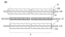
- the heat-resistant layer 24 may be arranged at least in the facing region R between the positive electrode 21 and the negative electrode 22 . In connection with this, the arrangement
- the heat-resistant layer 24 is provided in a range extending beyond the opposing region R, and more specifically, the heat-resistant layer 24 is provided in a winding inner side than the negative electrode active material layer 22B. and on the winding outside.
- FIG. 4 corresponding to FIG. may coincide with the arrangement range of the negative electrode active material layer 22B (Modification 1).
- the arrangement range of the heat-resistant layer 24 coincides with the opposing region R, and more specifically, the arrangement range of the heat-resistant layer 24 is the negative electrode active material. It may be narrower than the arrangement range of the layer 22B and may coincide with the arrangement range of the positive electrode active material layer 21B (Modification 2).
- the heat-resistant layer 24 is used to prevent a short circuit between the positive electrode 21 and the negative electrode 22, so that similar effects can be obtained.
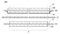
- the heat-resistant layer 24 is provided on the separator 23 , and more specifically, the heat-resistant layer 24 is provided on both sides of the separator 23 .
- the heat-resistant layers 24 are arranged at least in the opposing region R between the positive electrode 21 and the negative electrode 22, the number of the heat-resistant layers 24 provided can be changed arbitrarily.
- the heat-resistant layer 24 may be provided only on the upper surface of the separator 23, that is, only one surface of the separator 23 on the side facing the negative electrode 22 (modification 3).
- the heat-resistant layer 24 may be provided only on the lower surface of the separator 23, that is, only one surface of the separator 23 on the side facing the positive electrode 21 (Modification 4).
- the heat-resistant layer 24 is used to prevent a short circuit between the positive electrode 21 and the negative electrode 22, so that similar effects can be obtained.
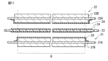
- the heat-resistant layer 24 is provided on the separator 23 .
- the location of the heat-resistant layer 24 can be changed arbitrarily.
- the heat-resistant layer 24 may be provided on each of the positive electrode 21 and the negative electrode 22 (Modification 5).
- the heat-resistant layer 24 is arranged between the positive electrode 21 and the separator 23 and the heat-resistant layer 24 is arranged between the negative electrode 22 and the separator 23 .
- the heat-resistant layer 24 may be provided only on the negative electrode 22 (Modification 6), or as shown in FIG. The layer 24 may be provided only on the positive electrode 21 (modification 7).
- the heat-resistant layers 24 are provided on both sides of the separator 23, and the heat-resistant layers 24 are provided on each of the positive electrode 21 and the negative electrode 22.
- the heat-resistant layer 24 is used to prevent a short circuit between the positive electrode 21 and the negative electrode 22, so that similar effects can be obtained.
- the electrolyte may contain other electrolyte salts along with the electrolyte salt containing the imide anion.
- the electrolyte contains lithium hexafluorophosphate as another electrolyte salt, and the content of the electrolyte salt in the electrolyte is appropriate in relation to the content of the other electrolyte salts in the electrolyte. It is preferable that the
- the electrolyte salt contains cations and imide anions.
- hexafluorophosphate ions include lithium ions and hexafluorophosphate ions.
- the sum T (mol/kg) of the cation content C1 in the electrolyte and the lithium ion content C2 in the electrolyte is 0.7 mol/kg to 2.2 mol/kg.
- the ratio R (mol %) of the number of moles M2 of the hexafluorophosphate ions in the electrolyte to the number of moles M1 of the imide anions in the electrolyte is 13 mol % to 6000 mol %. This is because the movement speeds of cations and lithium ions are sufficiently improved in the vicinity of the respective surfaces of the positive electrode 21 and the negative electrode 22, and the movement speeds of cations and lithium ions are also sufficiently improved in the liquid electrolyte. be.
- the “content of cations in the electrolyte” described here is the content of the electrolyte salt of cations in the solvent, and the “content of lithium ions in the electrolyte” is the content of lithium ions in the solvent.
- the secondary battery When calculating each of the sum T and the ratio R, the secondary battery is disassembled to collect the electrolytic solution, and then the electrolytic solution is analyzed using ICP emission spectrometry. As a result, the contents C1 and C2 and the numbers of moles M1 and M2 are specified, respectively, so that the sum T and the ratio R are calculated.
- the electrolytic solution contains the electrolyte salt, the same effect can be obtained.
- the electrolyte salt and another electrolyte salt lithium hexafluorophosphate
- the total amount (sum T) of both is optimized, and the mixing ratio (ratio R ) are also optimized.
- the movement speeds of cations and lithium ions in the vicinity of the surfaces of the positive electrode 21 and the negative electrode 22 are further improved, and the movement speeds of cations and lithium ions are further improved in the liquid electrolyte. Therefore, higher effects can be obtained.
- a laminated separator includes a porous membrane having a pair of surfaces and a polymer compound layer provided on one or both sides of the porous membrane. This is because the adhesiveness of the separator to each of the positive electrode 21 and the negative electrode 22 is improved, so that positional deviation (winding deviation) of the battery element 20 is suppressed. As a result, swelling of the secondary battery is suppressed even if a side reaction such as a decomposition reaction of the electrolytic solution occurs.
- the polymer compound layer contains a polymer compound such as polyvinylidene fluoride. This is because excellent physical strength and excellent electrochemical stability can be obtained.
- One or both of the porous membrane and the polymer compound layer may contain a plurality of insulating particles. This is because the safety (heat resistance) of the secondary battery is improved because the plurality of insulating particles promote heat dissipation when the secondary battery generates heat.
- the insulating particles contain one or more of insulating materials such as inorganic materials and resin materials. Specific examples of inorganic materials are aluminum oxide, aluminum nitride, boehmite, silicon oxide, titanium oxide, magnesium oxide and zirconium oxide. Specific examples of resin materials include acrylic resins and styrene resins.
- the precursor solution is applied to one or both sides of the porous membrane.
- a plurality of insulating particles may be added to the precursor solution.
- Modification 11 An electrolytic solution, which is a liquid electrolyte, was used. However, although not specifically illustrated here, an electrolyte layer that is a gel electrolyte may be used.
- the positive electrode 21 and the negative electrode 22 are laminated with the separator 23, the heat-resistant layer 24, and the electrolyte layer interposed therebetween, and the positive electrode 21, the negative electrode 22, the separator 23, the heat-resistant layer 24, and the electrolyte. Layers are wound. This electrolyte layer is interposed between the positive electrode 21 and the separator 23 and interposed between the negative electrode 22 and the separator 23 .
- the electrolyte layer contains a polymer compound together with an electrolytic solution, and the electrolytic solution is held by the polymer compound. This is because leakage of the electrolytic solution is prevented.
- the composition of the electrolytic solution is as described above.
- Polymer compounds include polyvinylidene fluoride and the like.
- a secondary battery used as a power source may be a main power source for electronic devices and electric vehicles, or may be an auxiliary power source.
- a main power source is a power source that is preferentially used regardless of the presence or absence of other power sources.
- the auxiliary power supply may be a power supply used in place of the main power supply, or may be a power supply switched from the main power supply.
- Secondary battery applications are as follows. Electronic devices such as video cameras, digital still cameras, mobile phones, laptop computers, headphone stereos, portable radios and portable information terminals. Backup power and storage devices such as memory cards. Power tools such as power drills and power saws. It is a battery pack mounted on an electronic device. Medical electronic devices such as pacemakers and hearing aids. It is an electric vehicle such as an electric vehicle (including a hybrid vehicle). It is a power storage system such as a home or industrial battery system that stores power in preparation for emergencies. In these uses, one secondary battery may be used, or a plurality of secondary batteries may be used.
- the battery pack may use a single cell or an assembled battery.
- An electric vehicle is a vehicle that operates (runs) using a secondary battery as a drive power source, and may be a hybrid vehicle that also includes a drive source other than the secondary battery.
- household electric power storage system household electric appliances and the like can be used by using electric power stored in a secondary battery, which is an electric power storage source.
- FIG. 12 shows the block configuration of the battery pack.
- the battery pack described here is a battery pack (a so-called soft pack) using one secondary battery, and is mounted in an electronic device such as a smart phone.
- This battery pack includes a power supply 51 and a circuit board 52, as shown in FIG.
- This circuit board 52 is connected to the power supply 51 and includes a positive terminal 53 , a negative terminal 54 and a temperature detection terminal 55 .
- the power supply 51 includes one secondary battery.
- the positive lead is connected to the positive terminal 53 and the negative lead is connected to the negative terminal 54 .
- the power supply 51 can be connected to the outside through the positive terminal 53 and the negative terminal 54, and thus can be charged and discharged.
- the circuit board 52 includes a control section 56 , a switch 57 , a PTC element 58 and a temperature detection section 59 .
- the PTC element 58 may be omitted.
- the control unit 56 includes a central processing unit (CPU), memory, etc., and controls the operation of the entire battery pack. This control unit 56 detects and controls the use state of the power supply 51 as necessary.
- CPU central processing unit
- memory etc.
- the control unit 56 cuts off the switch 57 so that the charging current does not flow through the current path of the power supply 51. make it
- the overcharge detection voltage is not particularly limited, but is specifically 4.20V ⁇ 0.05V, and the overdischarge detection voltage is not particularly limited, but is specifically 2.40V ⁇ 0.1V. is.
- the switch 57 includes a charge control switch, a discharge control switch, a charge diode, a discharge diode, and the like, and switches connection/disconnection between the power supply 51 and an external device according to instructions from the control unit 56 .
- the switch 57 includes a field effect transistor (MOSFET) using a metal oxide semiconductor, etc., and the charge/discharge current is detected based on the ON resistance of the switch 57 .
- MOSFET field effect transistor
- the temperature detection unit 59 includes a temperature detection element such as a thermistor, measures the temperature of the power supply 51 using the temperature detection terminal 55 , and outputs the temperature measurement result to the control unit 56 .
- the measurement result of the temperature measured by the temperature detection unit 59 is used when the control unit 56 performs charging/discharging control at the time of abnormal heat generation and when the control unit 56 performs correction processing when calculating the remaining capacity.
- the laminate film type secondary battery (lithium ion secondary battery) shown in FIGS. 1 and 2 was produced by the following procedure.
- the separator 23 shown in FIG. 3 that is, the separator 23 provided with the heat-resistant layer 24 on both sides was used.
- a positive electrode active material lithium-containing compound (oxide) (LiNi 0.82 Co 0.14 Al 0.04 O 2 ), 3 parts by mass of a positive electrode binder (polyvinylidene fluoride), a positive electrode conductor (carbon 6 parts by mass of black) were mixed with each other to form a positive electrode mixture.
- the positive electrode mixture was added to a solvent (N-methyl-2-pyrrolidone, which is an organic solvent), and the solvent was stirred.
- a coating device both sides of the positive electrode current collector 21A (a strip-shaped aluminum foil having a thickness of 12 ⁇ m) were coated with the positive electrode mixture slurry.
- the positive electrode mixture slurry was dried to form the positive electrode active material layer 21 B.
- the positive electrode active material layer 21 B was compression-molded using a roll press machine, thereby producing the positive electrode 21 .
- a negative electrode active material artificial graphite that is a carbon material
- a negative electrode binder polyvinylidene fluoride
- the organic solvent was stirred to prepare a pasty negative electrode mixture slurry.
- the negative electrode mixture slurry is applied to both surfaces of the negative electrode current collector 22A (band-shaped copper foil having a thickness of 15 ⁇ m) using a coating device, and then the negative electrode mixture slurry is dried to obtain a negative electrode active material.
- a material layer 22B is formed.
- the negative electrode active material layer 22B was compression molded using a roll press. Thus, the negative electrode 22 was produced.
- the polymer compound When a polymer compound was used as the heat-resistant material, the polymer compound was added to the solvent (N-methyl-2-pyrrolidone, which is an organic solvent), and then the solvent was stirred.
- the solvent N-methyl-2-pyrrolidone, which is an organic solvent
- PA1 para-type aromatic polyamide
- PA2 meta-type aromatic polyamide
- the solvent N-methyl-2-pyrrolidone, which is an organic solvent
- the solvent was stirred.
- oxides aluminum oxide (Al 2 O 3 ), titanium oxide (TiO 2 ), and silicon oxide (SiO 2 ) were used.
- PVDF Polyvinylidene fluoride
- PMMA polymethyl methacrylate
- a coated film was formed by applying the solution to both surfaces of the separator 23 (polyethylene microporous membrane having an average pore size of 17.9 nm) using a desktop coater. Finally, the separator 23 was placed in a water bath to cause phase separation of the coating film, and then the coating film was dried with hot air.
- the separator 23 polyethylene microporous membrane having an average pore size of 17.9 nm
- the procedure for producing the polyethylene microporous membrane, which is the separator 23, is as follows. First, a polyethylene solution was prepared by melt-kneading polyethylene and a plasticizer (liquid paraffin) using a twin-screw extruder. Subsequently, while extruding the polyethylene solution from a T-die attached to the tip of the twin-screw extruder, the polyethylene solution was wound up using a cooling roll to form a gel sheet. Subsequently, a thin film was obtained by biaxially stretching the gel-like sheet. Finally, residual liquid paraffin was extracted off by washing the thin film with a solvent (hexane), after which the thin film was dried and heat treated. As a result, the thin film was made microporous, and a microporous polyethylene film was obtained.
- a plasticizer liquid paraffin
- a heat-resistant layer was prepared according to the same procedure except that a non-heat-resistant material (polyethylene (PE), which is a polymer compound) was used instead of the heat-resistant material. 24 was formed.
- PE polyethylene
- Ethylene carbonate which is a cyclic carbonate
- ⁇ -butyrolactone which is a lactone
- Lithium ions (Li + ) were used as cations of the electrolyte salt.
- the anions of the electrolyte salt include the first imide anions shown in formulas (1-5), (1-6), formulas (1-21) and formulas (1-22), and formula (2-5 ), the tertiary imide anion represented by formula (3-5), and the quaternary imide anion represented by formula (4-37).
- the electrolyte salt content (mol/kg) was as shown in Tables 1 and 2.
- This electrolyte salt is a lithium salt containing an imide anion as an anion.
- the positive electrode lead 31 (aluminum foil) was welded to the positive electrode collector 21A of the positive electrode 21, and the negative electrode lead 32 (copper foil) was welded to the negative electrode collector 22A.
- the positive electrode 21 and the negative electrode 22 are laminated with each other via the separator 23 provided with the heat-resistant layer 24, and then the positive electrode 21, the negative electrode 22, the separator 23 and the heat-resistant layer 24 are wound to form a wound body. was made. Subsequently, the wound body was formed into a flat shape by pressing the wound body using a pressing machine.
- the exterior film 10 includes a fusion layer (a polypropylene film with a thickness of 30 ⁇ m), a metal layer (aluminum foil with a thickness of 40 ⁇ m), and a surface protective layer (a nylon film with a thickness of 25 ⁇ m). Aluminum laminate films laminated in this order from the inside were used.
- constant-current charging was performed at a current of 0.1C until the voltage reached 4.2V
- constant-voltage charging was performed at the voltage of 4.2V until the current reached 0.05C.
- constant current discharge was performed at a current of 0.1C until the voltage reached 2.5V.
- 0.1C is a current value that can fully discharge the battery capacity (theoretical capacity) in 10 hours
- 0.05C is a current value that fully discharges the battery capacity in 20 hours.
- the charging/discharging conditions were the same as the charging/discharging conditions during stabilization of the secondary battery described above.
- the secondary battery was repeatedly charged and discharged in the same environment until the total number of cycles reached 100 cycles, thereby measuring the discharge capacity (discharge capacity at the 100th cycle).
- the charging/discharging conditions were the same as the charging/discharging conditions during stabilization of the secondary battery described above.
- cycle retention rate (%) (discharge capacity at 100th cycle/discharge capacity at 1st cycle) x 100 is used to calculate the cycle retention rate, which is an index for evaluating high-temperature cycle characteristics. bottom.
- the charging/discharging conditions were the same as the charging/discharging conditions during stabilization of the secondary battery described above.
- the secondary battery is stored in a normal temperature environment.
- the discharge capacity discharge capacity after storage was measured by discharging the battery.
- the charging/discharging conditions were the same as the charging/discharging conditions during stabilization of the secondary battery described above.
- the storage retention rate (%) (discharge capacity after storage/discharge capacity before storage) x 100 was used to calculate the storage retention rate, which is an index for evaluating high-temperature storage characteristics.
- the charging/discharging conditions were the same as the charging/discharging conditions during stabilization of the secondary battery described above.
- the charge/discharge conditions were the same as the charge/discharge conditions during stabilization of the secondary battery described above, except that the current during discharge was changed to 1C.
- 1C is a current value that can discharge the battery capacity in 1 hour.
- load retention rate (discharge capacity at 100th cycle/discharge capacity at 1st cycle) x 100. bottom.
- the cycle retention rate, the storage retention rate, and the load retention rate are Both decreased.
- the cycle retention rate, the storage retention rate, and the load retention rate are Both increased.
- Examples 25 to 42> As shown in Tables 3 and 4, secondary batteries were produced in the same manner as in Example 3, except that the electrolytic solution contained either additives or other electrolyte salts. , evaluated the battery characteristics. In this case, either the additive or the other electrolyte salt was added to the solvent containing the electrolyte salt, and then the solvent was stirred.
- Vinylene carbonate (VC), vinyl ethylene carbonate (VEC) and methylene ethylene carbonate (MEC) were used as the unsaturated cyclic carbonate.
- fluorinated cyclic carbonate ethylene monofluorocarbonate (FEC) and ethylene difluorocarbonate (DFEC) were used.
- FEC ethylene monofluorocarbonate
- DFEC ethylene difluorocarbonate
- sulfonic acid esters propanesultone (PS) and propenesultone (PRS), which are cyclic monosulfonic acid esters, and cyclodison (CD), which is a cyclic disulfonic acid ester, were used.
- Succinic anhydride (SA) was used as the dicarboxylic anhydride.
- PSAH Propanedisulfonic anhydride
- DTD Ethylene sulfate
- Succinonitrile SN
- HMI Hexamethylene diisocyanate
- electrolyte salts include lithium hexafluorophosphate ( LiPF6 ), lithium tetrafluoroborate ( LiBF4 ), lithium bis(fluorosulfonyl)imide (LiFSI), lithium bis(oxalato)borate (LiBOB). and lithium difluorophosphate (LiPF 2 O 2 ) were used.
- LiPF6 lithium hexafluorophosphate
- LiBF4 lithium tetrafluoroborate
- LiFSI lithium bis(fluorosulfonyl)imide
- LiBOB lithium bis(oxalato)borate
- LiPF 2 O 2 lithium difluorophosphate
- Examples 43 to 74> As shown in Tables 5 and 6, a secondary battery was prepared in the same manner as in Example 3 except that the electrolyte solution contained another electrolyte salt (lithium hexafluorophosphate (LiPF 6 )). was produced, and the battery characteristics were evaluated.
- the electrolyte solution contained another electrolyte salt (lithium hexafluorophosphate (LiPF 6 )). was produced, and the battery characteristics were evaluated.
- LiPF 6 lithium hexafluorophosphate
- the heat-resistant layer 24 is arranged at least in the facing region R between the positive electrode 21 and the negative electrode 22, the heat-resistant layer 24 contains a heat-resistant material, and the electrolyte solution Cycle retention rate, storage retention rate and load retention rate were all improved when the electrolyte salt contained an imide anion. Therefore, excellent high-temperature cycle characteristics, excellent high-temperature storage characteristics, and excellent low-temperature load characteristics were obtained in the secondary battery, and thus excellent battery characteristics could be obtained.
- the element structure of the battery element is a wound type.
- the element structure of the battery element is not particularly limited, it may be a laminated type or a folded type.
- the positive electrode and the negative electrode are alternately laminated with a separator interposed therebetween, and in the multifold type, the positive electrode and the negative electrode are folded zigzag while facing each other with the separator interposed therebetween.
Abstract
二次電池は、正極活物質層を含む正極と、負極活物質層を含む負極と、その正極と負極との間に配置されたセパレータおよび耐熱層と、電解質塩を含む電解液とを備える。耐熱層は、少なくとも正極活物質層と負極活物質層とが互いに対向する領域に配置されていると共に、セパレータの融点または分解温度よりも高い融点または分解温度を有する。電解質塩は、イミドアニオンを含み、そのイミドアニオンは、式(1)で表される第1イミドアニオン、式(2)で表される第2イミドアニオン、式(3)で表される第3イミドアニオンおよび式(4)で表される第4イミドアニオンのうちの少なくとも1種を含む。
Description
本技術は、二次電池に関する。
携帯電話機などの多様な電子機器が普及しているため、小型かつ軽量であると共に高エネルギー密度が得られる電源として二次電池の開発が進められている。この二次電池は、正極および負極と共に電解液を備えており、その二次電池の構成に関しては、様々な検討がなされている。
具体的には、電解液がRF
1-S(=O)2 -NH-S(=O)2 -NH-S(=O)2 -RF
2で表されるイミド化合物を含んでいる(例えば、特許文献1参照。)。また、電解液の電解質塩がF-S(=O)2 -N- -C(=O)-N- -S(=O)2 -FまたはF-S(=O)2 -N- -S(=O)2 -C6 H4 -S(=O)2 -N- -S(=O)2 -Fで表されるイミドアニオンを含んでいる(例えば、非特許文献1,2参照。)。
Faiz Ahmed他,"Novel divalent organo-lithium salts with high electrochemical and thermal stability for aqueous rechargeable Li-Ion batteries ",Electrochimica Acta ,298 ,2019年,709-716
Faiz Ahmed他,"Highly conductive divalent fluorosulfonyl imide based electrolytes improving Li-ion battery performance :Additive potentiating ",Journal of Power Sources,455 ,2020年,227980
二次電池の構成に関する様々な検討がなされているが、その二次電池の電池特性は未だ十分でないため、改善の余地がある。
優れた電池特性を得ることが可能である二次電池が望まれている。
本技術の一実施形態の二次電池は、正極活物質層を含む正極と、負極活物質層を含む負極と、その正極と負極との間に配置されたセパレータおよび耐熱層と、電解質塩を含む電解液とを備えたものである。耐熱層は、少なくとも正極活物質層と負極活物質層とが互いに対向する領域に配置されていると共に、セパレータの融点または分解温度よりも高い融点または分解温度を有する。電解質塩は、イミドアニオンを含み、そのイミドアニオンは、式(1)で表される第1イミドアニオン、式(2)で表される第2イミドアニオン、式(3)で表される第3イミドアニオンおよび式(4)で表される第4イミドアニオンのうちの少なくとも1種を含む。


本技術の一実施形態の二次電池によれば、正極と負極との間にセパレータおよび耐熱層が配置されており、その耐熱層は少なくとも正極活物質層と負極活物質層とが互いに対向する領域に配置されていると共にセパレータの融点または分解温度よりも高い融点または分解温度を有しており、電解液の電解質塩がイミドアニオンとして第1イミドアニオン、第2イミドアニオン、第3イミドアニオンおよび第4イミドアニオンのうちの少なくとも1種を含んでいるので、優れた電池特性を得ることができる。
なお、本技術の効果は、必ずしもここで説明された効果に限定されるわけではなく、後述する本技術に関連する一連の効果のうちのいずれの効果でもよい。
以下、本技術の一実施形態に関して、図面を参照しながら詳細に説明する。なお、説明する順序は、下記の通りである。
1.二次電池
1-1.構成
1-2.動作
1-3.製造方法
1-4.作用および効果
2.変形例
3.二次電池の用途
1.二次電池
1-1.構成
1-2.動作
1-3.製造方法
1-4.作用および効果
2.変形例
3.二次電池の用途
<1.二次電池>
まず、本技術の一実施形態の二次電池に関して説明する。
まず、本技術の一実施形態の二次電池に関して説明する。
ここで説明する二次電池は、電極反応物質の吸蔵放出を利用して電池容量が得られる二次電池であり、正極および負極と共に電解液を備えている。
この二次電池では、負極の充電容量が正極の放電容量よりも大きくなっている。すなわち、負極の単位面積当たりの電気化学容量は、正極の単位面積当たりの電気化学容量よりも大きくなるように設定されている。充電途中において負極の表面に電極反応物質が析出することを防止するためである。
電極反応物質の種類は、特に限定されないが、具体的には、アルカリ金属およびアルカリ土類金属などの軽金属である。アルカリ金属の具体例は、リチウム、ナトリウムおよびカリウムなどであると共に、アルカリ土類金属の具体例は、ベリリウム、マグネシウムおよびカルシウムなどである。ただし、電極反応物質の種類は、アルミニウムなどの他の軽金属でもよい。
以下では、電極反応物質がリチウムである場合を例に挙げる。リチウムの吸蔵放出を利用して電池容量が得られる二次電池は、いわゆるリチウムイオン二次電池である。このリチウムイオン二次電池では、リチウムがイオン状態で吸蔵放出される。
<1-1.構成>
図1は、二次電池の斜視構成を表している。図2は、図1に示した電池素子20の一部の断面構成を表している。図3は、図1に示した電池素子20の全体の断面構成を表している。
図1は、二次電池の斜視構成を表している。図2は、図1に示した電池素子20の一部の断面構成を表している。図3は、図1に示した電池素子20の全体の断面構成を表している。
ただし、図1では、外装フィルム10と電池素子20とが互いに分離された状態を示していると共に、XZ面に沿った電池素子20の断面を破線で示している。図3では、正極21、負極22、セパレータ23および耐熱層24のそれぞれが巻回前において互いに分離された状態を示している。
この二次電池は、図1~図3に示したように、外装フィルム10と、電池素子20と、正極リード31と、負極リード32と、封止フィルム41,42とを備えている。ここで説明する二次電池は、可撓性または柔軟性を有する外装フィルム10を用いたラミネートフィルム型の二次電池である。
以下の説明では、図1~図3のそれぞれにおける上側を二次電池の上側とすると共に、図1~図3のそれぞれにおける下側を二次電池の下側とする。
[外装フィルムおよび封止フィルム]
外装フィルム10は、図1に示したように、電池素子20を収納する外装部材であり、その電池素子20が内部に収納された状態において封止された袋状の構造を有している。これにより、外装フィルム10は、正極21および負極22と共に電解液を収納している。
外装フィルム10は、図1に示したように、電池素子20を収納する外装部材であり、その電池素子20が内部に収納された状態において封止された袋状の構造を有している。これにより、外装フィルム10は、正極21および負極22と共に電解液を収納している。
ここでは、外装フィルム10は、1枚のフィルム状の部材であり、折り畳み方向Fに折り畳まれている。この外装フィルム10には、電池素子20を収容するための窪み部10U(いわゆる深絞り部)が設けられている。
具体的には、外装フィルム10は、融着層、金属層および表面保護層が内側からこの順に積層された3層のラミネートフィルムであり、その外装フィルム10が折り畳まれた状態において、互いに対向する融着層のうちの外周縁部同士が互いに融着されている。融着層は、ポリプロピレンなどの高分子化合物を含んでいる。金属層は、アルミニウムなどの金属材料を含んでいる。表面保護層は、ナイロンなどの高分子化合物を含んでいる。
ただし、外装フィルム10の構成(層数)は、特に限定されないため、1層または2層でもよいし、4層以上でもよい。
封止フィルム41は、外装フィルム10と正極リード31との間に挿入されていると共に、封止フィルム42は、外装フィルム10と負極リード32との間に挿入されている。ただし、封止フィルム41,42のうちの一方または双方は、省略されてもよい。
この封止フィルム41は、外装フィルム10の内部に外気などが侵入することを防止する封止部材である。また、封止フィルム41は、正極リード31に対して密着性を有するポリオレフィンなどの高分子化合物を含んでおり、その高分子化合物の具体例は、ポリプロピレンなどである。
封止フィルム42の構成は、負極リード32に対して密着性を有する封止部材であることを除いて、封止フィルム41の構成と同様である。すなわち、封止フィルム42は、負極リード32に対して密着性を有するポリオレフィンなどの高分子化合物を含んでいる。
[電池素子]
電池素子20は、図1~図3に示したように、正極21と、負極22と、セパレータ23と、耐熱層24と、電解液(図示せず)とを含む発電素子であり、外装フィルム10の内部に収納されている。
電池素子20は、図1~図3に示したように、正極21と、負極22と、セパレータ23と、耐熱層24と、電解液(図示せず)とを含む発電素子であり、外装フィルム10の内部に収納されている。
この電池素子20は、いわゆる巻回電極体である。すなわち、正極21および負極22は、セパレータ23および耐熱層24を介して互いに積層されていると共に、そのセパレータ23および耐熱層24を介して互いに対向しながら巻回軸Pを中心として巻回されている。なお、巻回軸Pは、Y軸方向に延在する仮想軸である。
電池素子20の立体的形状は、特に限定されない。ここでは、電池素子20の立体的形状は、扁平状であるため、巻回軸Pと交差する電池素子20の断面(XZ面に沿った断面)の形状は、長軸J1および短軸J2により画定される扁平形状である。この長軸J1は、X軸方向に延在すると共に短軸J2よりも大きい長さを有する仮想軸である。また、短軸J2は、X軸方向と交差するZ軸方向に延在すると共に長軸J1よりも小さい長さを有する仮想軸である。ここでは、電池素子20の立体的形状は、扁平な円筒状であるため、その電池素子20の断面の形状は、扁平な略楕円である。
(正極)
正極21は、図2に示したように、正極集電体21Aおよび正極活物質層21Bを含んでいる。
正極21は、図2に示したように、正極集電体21Aおよび正極活物質層21Bを含んでいる。
正極集電体21Aは、正極活物質層21Bが設けられる一対の面を有している。この正極集電体21Aは、金属材料などの導電性材料を含んでおり、その導電性材料の具体例は、アルミニウムなどである。
正極活物質層21Bは、リチウムを吸蔵放出する正極活物質のうちのいずれか1種類または2種類以上を含んでいる。ただし、正極活物質層21Bは、さらに、正極結着剤および正極導電剤などの他の材料のうちのいずれか1種類または2種類以上を含んでいてもよい。
ここでは、正極活物質層21Bは、正極集電体21Aの両面に設けられている。ただし、正極活物質層21Bは、正極21が負極22に対向する側において正極集電体21Aの片面だけに設けられていてもよい。正極活物質層21Bの形成方法は、特に限定されないが、具体的には、塗布法などである。
正極活物質の種類は、特に限定されないが、具体的には、リチウム含有化合物である。このリチウム含有化合物は、リチウムと共に1種類または2種類以上の遷移金属元素を構成元素として含む化合物であり、さらに、1種類または2種類以上の他元素を構成元素として含んでいてもよい。他元素の種類は、リチウムおよび遷移金属元素のそれぞれ以外の元素であれば、特に限定されないが、具体的には、長周期型周期表中の2族~15族に属する元素である。リチウム含有化合物の種類は、特に限定されないが、具体的には、酸化物、リン酸化合物、ケイ酸化合物およびホウ酸化合物などである。
酸化物の具体例は、LiNiO2 、LiCoO2 、LiCo0.98Al0.01Mg0.01O2 、LiNi0.5 Co0.2 Mn0.3 O2 、LiNi0.8 Co0.15Al0.05O2 、LiNi0.33Co0.33Mn0.33O2 、Li1.2 Mn0.52Co0.175 Ni0.1 O2 、Li1.15(Mn0.65Ni0.22Co0.13)O2 およびLiMn2 O4 などである。リン酸化合物の具体例は、LiFePO4 、LiMnPO4 、LiFe0.5 Mn0.5 PO4 およびLiFe0.3 Mn0.7 PO4 などである。
正極結着剤は、合成ゴムおよび高分子化合物などのうちのいずれか1種類または2種類以上を含んでいる。合成ゴムの具体例は、スチレンブタジエン系ゴム、フッ素系ゴムおよびエチレンプロピレンジエンなどである。高分子化合物の具体例は、ポリフッ化ビニリデン、ポリイミドおよびカルボキシメチルセルロースなどである。
正極導電剤は、炭素材料などの導電性材料のうちのいずれか1種類または2種類以上を含んでいる。炭素材料の具体例は、黒鉛、カーボンブラック、アセチレンブラックおよびケッチェンブラックなどである。ただし、導電性材料は、金属材料および高分子化合物などでもよい。
(負極)
負極22は、図2に示したように、負極集電体22Aおよび負極活物質層22Bを含んでいる。
負極22は、図2に示したように、負極集電体22Aおよび負極活物質層22Bを含んでいる。
負極集電体22Aは、負極活物質層22Bが設けられる一対の面を有している。この負極集電体22Aは、金属材料などの導電性材料を含んでおり、その金属材料の具体例は、銅などである。
負極活物質層22Bは、リチウムを吸蔵放出する負極活物質のうちのいずれか1種類または2種類以上を含んでいる。ただし、負極活物質層22Bは、さらに、負極結着剤および負極導電剤などの他の材料のうちのいずれか1種類または2種類以上を含んでいてもよい。
ここでは、負極活物質層22Bは、負極集電体22Aの両面に設けられている。ただし、負極活物質層22Bは、負極22が正極21に対向する側において負極集電体22Aの片面だけに設けられていてもよい。負極活物質層22Bの形成方法は、特に限定されないが、具体的には、塗布法、気相法、液相法、溶射法および焼成法(焼結法)などのうちのいずれか1種類または2種類以上である。
負極活物質の種類は、特に限定されないが、具体的には、炭素材料および金属系材料などである。高いエネルギー密度が得られるからである。なお、負極活物質は、炭素材料および金属系材料のうちのいずれか一方だけを含んでいてもよいし、双方を含んでいてもよい。
炭素材料の具体例は、易黒鉛化性炭素、難黒鉛化性炭素および黒鉛などである。この黒鉛は、天然黒鉛でもよいし、人造黒鉛でもよいし、双方でもよい。
金属系材料は、リチウムと合金を形成可能である金属元素および半金属元素のうちのいずれか1種類または2種類以上を構成元素として含む材料であり、その金属元素および半金属元素の具体例は、ケイ素およびスズなどである。この金属系材料は、単体でもよいし、合金でもよいし、化合物でもよいし、それらの2種類以上の混合物でもよいし、それらの2種類以上の相を含む材料でもよい。金属系材料の具体例は、TiSi2 およびSiOx (0<x≦2または0.2<x<1.4)などである。
負極結着剤および負極導電剤のそれぞれに関する詳細は、正極結着剤および正極導電剤のそれぞれに関する詳細と同様である。
(対向領域および非対向領域)
ここでは、図3に示したように、正極活物質層21Bは、正極集電体21Aの表面のうちの一部に設けられていると共に、負極活物質層22Bは、負極集電体22Aの表面のうちの一部に設けられている。
ここでは、図3に示したように、正極活物質層21Bは、正極集電体21Aの表面のうちの一部に設けられていると共に、負極活物質層22Bは、負極集電体22Aの表面のうちの一部に設けられている。
具体的には、正極活物質層21Bは、正極集電体21Aが長手方向(図3中の左右方向)に延在している場合において、その長手方向における正極集電体21Aの表面のうちの中央領域に配置されている。これにより、正極集電体21Aの表面のうちの中央領域は、正極活物質層21Bにより被覆されている。これに対して、正極集電体21Aの表面のうちの巻内側の端部領域は、正極活物質層21Bにより被覆されておらずに露出していると共に、その正極集電体21Aの表面のうちの巻外側の端部領域は、正極活物質層21Bにより被覆されておらずに露出している。
また、負極活物質層22Bは、負極集電体22Aが長手方向(図3中の左右方向)に延在している場合において、その長手方向における負極集電体22Aの表面のうちの中央領域に配置されている。これにより、負極集電体22Aの表面のうちの中央領域は、負極活物質層22Bにより被覆されている。これに対して、負極集電体22Aの表面のうちの巻内側の端部領域は、負極活物質層22Bにより被覆されておらずに露出していると共に、その負極集電体22Aの表面のうちの巻外側の端部領域は、負極活物質層22Bにより被覆されておらずに露出している。
ただし、長手方向における負極活物質層22Bの配設範囲は、その長手方向における正極活物質層21Bの配設範囲よりも巻内側に拡張されていると共に、その長手方向における正極活物質層21Bの配設範囲よりも巻外側に拡張されている。これにより、正極21および負極22では、正極活物質層21Bと負極活物質層22Bとが互いに対向する領域(対向領域R)と、その正極活物質層21Bと負極活物質層22Bとが互いに対向しない領域(非対向領域)とが存在している。負極活物質層22Bでは、対向領域Rに配置されている部分は充放電に関与するが、その対向領域Rに配置されていない部分は充放電にほとんど関与しない。
負極活物質層22Bの配設範囲が正極活物質層21Bの配設範囲よりも拡張されているため、正極21および負極22において対向領域Rおよび非対向領域が存在しているのは、充放電可能な領域(対向領域R)を担保しながら、負極集電体22Aの表面においてリチウム金属が意図せずに析出することを防止するためである。
(セパレータ)
セパレータ23は、図2および図3に示したように、正極21と負極22との間に配置されている絶縁性の多孔質膜であり、その正極21と負極22との接触(短絡)を防止しながらリチウムイオンを通過させる。このセパレータ23は、ポリエチレンなどの高分子化合物を含んでいる。
セパレータ23は、図2および図3に示したように、正極21と負極22との間に配置されている絶縁性の多孔質膜であり、その正極21と負極22との接触(短絡)を防止しながらリチウムイオンを通過させる。このセパレータ23は、ポリエチレンなどの高分子化合物を含んでいる。
(電解液)
電解液は、液状の電解質である。この電解液は、正極21、負極22、セパレータ23および耐熱層24のそれぞれに含浸されており、電解質塩を含んでいる。より具体的には、電解液は、電解質塩と共に、その電解質塩を分散(電離)させる溶媒を含んでいる。
電解液は、液状の電解質である。この電解液は、正極21、負極22、セパレータ23および耐熱層24のそれぞれに含浸されており、電解質塩を含んでいる。より具体的には、電解液は、電解質塩と共に、その電解質塩を分散(電離)させる溶媒を含んでいる。
(電解質塩)
電解質塩は、溶媒中において電離する化合物であり、アニオンおよびカチオンを含んでいる。
電解質塩は、溶媒中において電離する化合物であり、アニオンおよびカチオンを含んでいる。
(アニオン)
アニオンは、イミドアニオンを含んでいる。具体的には、イミドアニオンは、式(1)で表される第1イミドアニオン、式(2)で表される第2イミドアニオン、式(3)で表される第3イミドアニオンおよび式(4)で表される第4イミドアニオンのうちのいずれか1種類または2種類以上を含んでいる。すなわち、電解質塩は、アニオンとしてイミドアニオンを含んでいる。
アニオンは、イミドアニオンを含んでいる。具体的には、イミドアニオンは、式(1)で表される第1イミドアニオン、式(2)で表される第2イミドアニオン、式(3)で表される第3イミドアニオンおよび式(4)で表される第4イミドアニオンのうちのいずれか1種類または2種類以上を含んでいる。すなわち、電解質塩は、アニオンとしてイミドアニオンを含んでいる。
ただし、第1イミドアニオンの種類は、1種類だけでもよいし、2種類以上でもよい。このように種類が1種類でも2種類以上でもよいことは、第2イミドアニオン、第3イミドアニオンおよび第4イミドアニオンのそれぞれに関しても同様である。


アニオンがイミドアニオンを含んでいる理由は、以下で説明する通りである。第1に、二次電池の充放電時において、電解質塩に由来する良質な被膜が正極21および負極22のそれぞれの表面に形成されるからである。これにより、正極21および負極22のそれぞれとの反応に起因する電解液(特に溶媒)の分解反応が抑制される。第2に、上記した被膜を利用して、正極21および負極22のそれぞれの表面近傍においてリチウムイオンの移動速度が向上する。第3に、電解液の液中においても、リチウムイオンの移動速度が向上する。
第1イミドアニオンは、式(1)に示したように、2個の窒素原子(N)および3個の官能基(W1~W3)を含む鎖状のアニオン(2価のマイナスイオン)である。
R1およびR2のそれぞれは、フッ素基(-F)およびフッ素化アルキル基のうちのいずれかであれば、特に限定されない。すなわち、R1およびR2のそれぞれは、互いに同じ基でもよいし、互いに異なる基でもよい。これにより、R1およびR2のそれぞれは、水素基(-H)およびアルキル基などではない。
フッ素化アルキル基は、アルキル基のうちの1個または2個以上の水素基(-H)がフッ素基により置換された基である。ただし、フッ素化アルキル基は、直鎖状でもよいし、1本または2本以上の側鎖を有する分岐状でもよい。
フッ素化アルキル基の炭素数は、特に限定されないが、具体的には、1~10である。第1イミドアニオンを含む電解質塩の溶解性および電離性が向上するからである。
フッ素化アルキル基の具体例は、パーフルオロメチル基(-CF3 )およびパーフルオロエチル基(-C2 F5 )などである。
W1~W3のそれぞれは、カルボニル基、スルフィニル基およびスルホニル基のうちのいずれかであれば、特に限定されない。すなわち、W1~W3のそれぞれは、互いに同じ基でもよいし、互いに異なる基でもよい。もちろん、W1~W3のうちの任意の2つだけが互いに同じ基でもよい。
第2イミドアニオンは、式(2)に示したように、3個の窒素原子および4個の官能基(X1~X4)を含む鎖状のアニオン(3価のマイナスイオン)である。
R3およびR4のそれぞれに関する詳細は、R1およびR2のそれぞれに関する詳細と同様である。
X1~X4のそれぞれは、カルボニル基、スルフィニル基およびスルホニル基のうちのいずれかであれば、特に限定されない。すなわち、X1~X4のそれぞれは、互いに同じ基でもよいし、互いに異なる基でもよい。もちろん、X1~X4のうちの任意の2つだけが互いに同じ基でもよいし、X1~X4のうちの任意の3つだけが互いに同じ基でもよい。
第3イミドアニオンは、式(3)に示したように、2個の窒素原子、3個の官能基(Y1~Y3)および1個の接続基(R5)を含む環状のアニオン(2価のマイナスイオン)である。
R5であるフッ素化アルキレン基は、アルキレン基のうちの1個または2個以上の水素基がフッ素基により置換された基である。ただし、フッ素化アルキレン基は、直鎖状でもよいし、1本または2本以上の側鎖を有する分岐状でもよい。
フッ素化アルキレン基の炭素数は、特に限定されないが、具体的には、1~10である。第3イミドアニオンを含む電解質塩の溶解性および電離性が向上するからである。
フッ素化アルキレン基の具体例は、パーフルオロメチレン基(-CF2 -)およびパーフルオロエチレン基(-C2 F4 -)などである。
Y1~Y3のそれぞれは、カルボニル基、スルフィニル基およびスルホニル基のうちのいずれかであれば、特に限定されない。すなわち、Y1~Y3のそれぞれは、互いに同じ基でもよいし、互いに異なる基でもよい。もちろん、Y1~Y3のうちの任意の2つだけが互いに同じ基でもよい。
第4イミドアニオンは、式(4)に示したように、2個の窒素原子(N)、4個の官能基(Z1~Z4)および1個の接続基(R8)を含む鎖状のアニオン(2価のマイナスイオン)である。
R6およびR7のそれぞれに関する詳細は、R1およびR2のそれぞれに関する詳細と同様である。
R8は、アルキレン基、フェニレン基、フッ素化アルキレン基およびフッ素化フェニレン基のうちのいずれかであれば、特に限定されない。
アルキレン基は、直鎖状でもよいし、1本または2本以上の側鎖を有する分岐状でもよい。アルキレン基の炭素数は、特に限定されないが、具体的には、1~10である。第4イミドアニオンを含む電解質塩の溶解性および電離性が向上するからである。アルキレン基の具体例は、メチレン基(-CH2 -)、エチレン基(-C2 H4 -)およびプロピレン基(-C3 H6 -)などである。
R8であるフッ素化アルキレン基に関する詳細は、R5であるフッ素化アルキレン基に関する詳細と同様である。
フッ素化フェニレン基は、フェニレン基のうちの1個または2個以上の水素基がフッ素基により置換された基である。フッ素化フェニレン基の具体例は、モノフルオロフェニレン基(-C6 H3 F-)などである。
Z1~Z4のそれぞれは、カルボニル基、スルフィニル基およびスルホニル基のうちのいずれかであれば、特に限定されない。すなわち、Z1~Z4のそれぞれは、互いに同じ基でもよいし、互いに異なる基でもよい。もちろん、Z1~Z4のうちの任意の2つだけが互いに同じ基でもよいし、Z1~Z4のうちの任意の3つだけが互いに同じ基でもよい。
第1イミドアニオンの具体例は、式(1-1)~式(1-30)のそれぞれで表されるアニオンなどである。


第2イミドアニオンの具体例は、式(2-1)~式(2-22)のそれぞれで表されるアニオンなどである。


第3イミドアニオンの具体例は、式(3-1)~式(3-15)のそれぞれで表されるアニオンなどである。

第4イミドアニオンの具体例は、式(4-1)~式(4-65)のそれぞれで表されるアニオンなどである。


(カチオン)
カチオンの種類は、特に限定されない。具体的には、カチオンは、軽金属イオンのうちのいずれか1種類または2種類以上を含んでいる。すなわち、電解質塩は、カチオンとして軽金属イオンを含んでいる。高い電圧が得られるからである。
カチオンの種類は、特に限定されない。具体的には、カチオンは、軽金属イオンのうちのいずれか1種類または2種類以上を含んでいる。すなわち、電解質塩は、カチオンとして軽金属イオンを含んでいる。高い電圧が得られるからである。
軽金属イオンの種類は、特に限定されないが、具体的には、アルカリ金属イオンおよびアルカリ土類金属イオンなどである。アルカリ金属イオンの具体例は、ナトリウムイオンおよびカリウムイオンなどである。アルカリ土類金属イオンの具体例は、ベリリウムイオン、マグネシウムイオンおよびカルシウムイオンなどである。この他、軽金属イオンは、アルミニウムイオンなどでもよい。
中でも、軽金属イオンは、リチウムイオンを含んでいることが好ましい。十分に高い電圧が得られるからである。
(含有量)
電解液における電解質塩の含有量は、特に限定されないため、任意に設定可能である。中でも、電解質塩の含有量は、0.2mol/kg~2mol/kgであることが好ましい。高いイオン伝導性が得られるからである。ここで説明した「電解質塩の含有量」とは、溶媒に対する電解質塩の含有量である。
電解液における電解質塩の含有量は、特に限定されないため、任意に設定可能である。中でも、電解質塩の含有量は、0.2mol/kg~2mol/kgであることが好ましい。高いイオン伝導性が得られるからである。ここで説明した「電解質塩の含有量」とは、溶媒に対する電解質塩の含有量である。
電解質塩の含有量を特定する場合には、二次電池を解体することにより、電解液を回収したのち、高周波誘導結合プラズマ(Inductively Coupled Plasma(ICP))発光分光分析法を用いて電解液を分析する。これにより、溶媒の重量および電解質塩の重量のそれぞれが特定されるため、その電解質塩の含有量が算出される。
ここで説明した含有量の特定手順は、後述する電解質塩以外の電解液の成分の含有量を特定する場合に関しても同様である。
(溶媒)
溶媒は、非水溶媒(有機溶剤)のうちのいずれか1種類または2種類以上を含んでおり、その非水溶媒を含んでいる電解液は、いわゆる非水電解液である。非水溶媒は、エステル類およびエーテル類などであり、より具体的には、炭酸エステル系化合物、カルボン酸エステル系化合物およびラクトン系化合物などである。
溶媒は、非水溶媒(有機溶剤)のうちのいずれか1種類または2種類以上を含んでおり、その非水溶媒を含んでいる電解液は、いわゆる非水電解液である。非水溶媒は、エステル類およびエーテル類などであり、より具体的には、炭酸エステル系化合物、カルボン酸エステル系化合物およびラクトン系化合物などである。
炭酸エステル系化合物は、環状炭酸エステルおよび鎖状炭酸エステルなどである。環状炭酸エステルの具体例は、炭酸エチレンおよび炭酸プロピレンなどである。鎖状炭酸エステルの具体例は、炭酸ジメチル、炭酸ジエチルおよび炭酸エチルメチルなどである。
カルボン酸エステル系化合物は、鎖状カルボン酸エステルなどである。鎖状カルボン酸エステルの具体例は、酢酸メチル、酢酸エチル、プロピオン酸メチル、プロピオン酸エチル、プロピオン酸プロピル、トリメチル酢酸エチル、酪酸メチルおよび酪酸エチルなどである。
ラクトン系化合物は、ラクトンなどである。ラクトンの具体例は、γ-ブチロラクトンおよびγ-バレロラクトンなどである。
なお、エーテル類は、1,2-ジメトキシエタン、テトラヒドロフラン、1,3-ジオキソランおよび1,4-ジオキサンなどでもよい。
(他の電解質塩)
なお、電解液は、さらに、他の電解質塩のうちのいずれか1種類または2種類以上を含んでいてもよい。正極21および負極22のそれぞれの表面近傍においてリチウムイオンの移動速度がより向上すると共に、電解液の液中においてもリチウムイオンの移動速度がより向上するからである。電解液における他の電解質塩の含有量は、特に限定されないため、任意に設定可能である。
なお、電解液は、さらに、他の電解質塩のうちのいずれか1種類または2種類以上を含んでいてもよい。正極21および負極22のそれぞれの表面近傍においてリチウムイオンの移動速度がより向上すると共に、電解液の液中においてもリチウムイオンの移動速度がより向上するからである。電解液における他の電解質塩の含有量は、特に限定されないため、任意に設定可能である。
他の電解質塩の種類は、特に限定されないが、具体的には、リチウム塩などの軽金属塩である。ただし、上記した電解質塩は、ここで説明するリチウム塩から除かれる。
リチウム塩の具体例は、六フッ化リン酸リチウム(LiPF6 )、四フッ化ホウ酸リチウム(LiBF4 )、トリフルオロメタンスルホン酸リチウム(LiCF3 SO3 )、ビス(フルオロスルホニル)イミドリチウム(LiN(FSO2 )2 )、ビス(トリフルオロメタンスルホニル)イミドリチウム(LiN(CF3 SO2 )2 )、リチウムトリス(トリフルオロメタンスルホニル)メチド(LiC(CF3 SO2 )3 )、ビス(オキサラト)ホウ酸リチウム(LiB(C2 O4 )2 )、ジフルオロオキサラトホウ酸リチウム(LiBF2 (C2 O4 ))、ジフルオロジ(オキサラト)ホウ酸リチウム(LiPF2 (C2 O4 )2 )およびテトラフルオロオキサラトリン酸リチウム(LiPF4 (C2 O4 ))、モノフルオロリン酸リチウム(Li2 PFO3 )およびジフルオロリン酸リチウム(LiPF2 O2 )などである。
中でも、他の電解質塩は、六フッ化リン酸リチウム、四フッ化ホウ酸リチウム、ビス(フルオロスルホニル)イミドリチウム、ビス(オキサラト)ホウ酸リチウムおよびジフルオロリン酸リチウムのうちのいずれか1種類または2種類以上を含んでいることが好ましい。正極21および負極22のそれぞれの表面近傍においてリチウムイオンの移動速度が十分に向上すると共に、電解液の液中においてもリチウムイオンの移動速度が十分に向上するからである。
(添加剤)
また、電解液は、さらに、添加剤のうちのいずれか1種類または2種類以上を含んでいてもよい。二次電池の充放電時において、添加剤に由来する被膜が正極21および負極22のそれぞれの表面に形成されるため、電解液の分解反応が抑制されるからである。なお、電解液における添加剤の含有量は、特に限定されないため、任意に設定可能である。
また、電解液は、さらに、添加剤のうちのいずれか1種類または2種類以上を含んでいてもよい。二次電池の充放電時において、添加剤に由来する被膜が正極21および負極22のそれぞれの表面に形成されるため、電解液の分解反応が抑制されるからである。なお、電解液における添加剤の含有量は、特に限定されないため、任意に設定可能である。
添加剤の種類は、特に限定されないが、具体的には、不飽和環状炭酸エステル、フッ素化環状炭酸エステル、スルホン酸エステル、ジカルボン酸無水物、ジスルホン酸無水物、硫酸エステル、ニトリル化合物およびイソシアネート化合物などである。
不飽和環状炭酸エステルは、不飽和炭素結合(炭素間二重結合)を含む環状炭酸エステルである。不飽和炭素結合の数は、特に限定されないため、1個だけでもよいし、2個以上でもよい。不飽和環状炭酸エステルの具体例は、炭酸ビニレン、炭酸ビニルエチレンおよび炭酸メチレンエチレンなどである。
フッ素化環状炭酸エステルは、フッ素を構成元素として含む環状炭酸エステルである。すなわち、フッ素化環状炭酸エステルは、環状炭酸エステルのうちの1個または2個以上の水素基がフッ素基により置換された化合物である。フッ素化環状炭酸エステルの具体例は、モノフルオロ炭酸エチレンおよびジフルオロ炭酸エチレンなどである。
スルホン酸エステルは、環状モノスルホン酸エステル、環状ジスルホン酸エステル、鎖状モノスルホン酸エステルおよび鎖状ジスルホン酸エステルなどである。環状モノスルホン酸エステルの具体例は、1,3-プロパンスルトン、1-プロペン-1,3-スルトン、1,4-ブタンスルトン、2,4-ブタンスルトンおよびメタンスルホン酸プロパルギルエステルなどである。環状ジスルホン酸エステルの具体例は、シクロジソンなどである。
ジカルボン酸無水物の具体例は、無水コハク酸、無水グルタル酸および無水マレイン酸などである。
ジスルホン酸無水物の具体例は、無水エタンジスルホン酸および無水プロパンジスルホン酸などである。
硫酸エステルの具体例は、エチレンスルファート(1,3,2-ジオキサチオラン 2,2-ジオキシド)などである。
ニトリル化合物は、1個または2個以上のシアノ基(-CN)を含む化合物である。ニトリル化合物の具体例は、オクタンニトリル、ベンゾニトリル、フタロニトリル、スクシノニトリル、グルタロニトリル、アジポニトリル、セバコニトリル、1,3,6-ヘキサントリカルボニトリル、3,3’-オキシジプロピオニトリル、3-ブトキシプロピオニトリル、エチレングリコールビスプロピオニトリルエーテル、1,2,2,3-テトラシアノプロパン、テトラシアノプロパン、フマロニトリル、7,7,8,8-テトラシアノキノジメタン、シクロペンタンカルボニトリル、1,3,5-シクロヘキサントリカルボニトリルおよび1,3-ビス(ジシアノメチリデン)インダンなどである。
イソシアネート化合物は、1個または2個以上のイソシアネート基(-NCO)を含む化合物である。イソシアネート化合物の具体例は、ヘキサメチレンジイソシアネートなどである。
(耐熱層)
耐熱層24は、図2に示したように、正極21と負極22との間に配置されており、正極21と負極22との短絡を防止する。
耐熱層24は、図2に示したように、正極21と負極22との間に配置されており、正極21と負極22との短絡を防止する。
この耐熱層24は、正極21と負極22との間において、少なくとも対向領域Rに配置されている。すなわち、耐熱層24の配設範囲は、対向領域Rだけでもよいし、その対向領域Rより拡張された領域でもよい。
ここでは、図3に示したように、耐熱層24は、対向領域Rより拡張された領域に配置されている。この場合において、耐熱層24の配設範囲は、対向領域Rより巻内側に拡張されていると共に、その対向領域Rより巻外側に拡張されている。正極21と負極22との短絡がより防止されるからである。
また、図3に示したように、耐熱層24は、セパレータ23に設けられている。後述するように、耐熱層24が正極21または負極22に設けられている場合と比較して、その耐熱層24の取り扱い性が向上するため、二次電池の製造工程が容易になるからである。
具体的には、セパレータ23は、耐熱層24が設けられる一対の面を有しており、その耐熱層24は、セパレータ23の両面に設けられている。このセパレータ23の両面は、正極21と対向する側におけるセパレータ23の表面と、負極22と対向する側におけるセパレータ23の表面とである。これにより、耐熱層24は、正極21とセパレータ23との間に介在していると共に、負極22とセパレータ23との間に介在している。
この耐熱層24は、耐熱性材料のうちのいずれか1種類または2種類以上を含んでいる。二次電池の発熱などに起因する高温環境下において、セパレータ23が溶融または溶断しても正極21と負極22との間に耐熱層24が介在し続けるため、その正極21と負極22と短絡が防止されるからである。
この耐熱性材料は、セパレータ23の融点または分解温度よりも高い融点または分解温度を有する材料である。すなわち、耐熱層24は、セパレータ23の融点または分解温度よりも高い融点または分解温度を有している。これに対して、セパレータ23の融点または分解温度よりも低い融点または分解温度を有する材料は、非耐熱性材料である。
耐熱性材料の種類は、特に限定されないが、中でも、その耐熱性材料の融点または分解温度は、約200℃以上であることが好ましく、約210℃~2100℃であることがより好ましい。セパレータ23は、上記したように、高分子化合物を含んでいるため、耐熱性材料の融点または分解温度が上記した範囲であると、耐熱層24の融点または分解温度がセパレータ23の融点または分解温度が高いという条件が満たされやすくなるからである。また、熱暴走時においてリチウムイオン二次電池の温度は約200℃以上まで到達するため、耐熱性材料の融点または分解温度が上記した範囲であると、上記した耐熱層24に関する条件が満たされやすくなるからである。
なお、リチウムイオン二次電池の熱暴走時の温度は、正極活物質と負極活物質との組み合わせに応じて異なる場合がある。具体的には、正極活物質が層状岩塩型の結晶構造を有するリチウム含有化合物を含んでいると共に、負極活物質がリチウムを吸蔵放出する材料を含んでいる場合には、熱暴走が発生しやすくなる。正極活物質(層状岩塩型の結晶構造を有するリチウム含有化合物)の具体例は、上記したLiCoO2 などの酸化物であると共に、負極活物質(リチウムを吸蔵放出する材料)の具体例は、上記した炭素材料および金属系材料などである。このため、融点または分解温度が約200℃以上であるという耐熱性材料の物性は、熱暴走が発生しやすいリチウムイオン二次電池に用いられる耐熱層24の構成材料として適切である。
耐熱層24の厚さは、特に限定されないが、具体的には、0.1μm~10μmであり、好ましくは0.5μm~5μmである。電気抵抗の増加が抑制されながら、耐熱層24において優れた耐熱性が得られるからである。また、耐熱層24の密度は、特に限定されないが、具体的には、上記した厚さと同様の理由により、0.01mg/cm2 ~10mg/cm2 である。
(耐熱性材料(高分子化合物))
より具体的には、耐熱性材料は、高分子化合物のうちのいずれか1種類または2種類以上を含んでいる。耐熱層24において優れた熱安定性が得られると共に、その耐熱層24が容易に形成可能になるからである。
より具体的には、耐熱性材料は、高分子化合物のうちのいずれか1種類または2種類以上を含んでいる。耐熱層24において優れた熱安定性が得られると共に、その耐熱層24が容易に形成可能になるからである。
高分子化合物の種類は、特に限定されないが、具体的には、ポリアミド、ポリスチレン、ポリアクリル酸エステル、ポリメタクリル酸エステル、ポリカーボネート、ポリエチレンテレフタレート、ポリブチレンテレフタレート、ポリフェニレンサルファイド、ポリスルホン、ポリエーテルスルホン、ポリエーテルエーテルケトン、ポリテトラフルオロエチレン、ポリイミド、ポリエーテルイミド、メラミン、ベンゾグアナミンおよびポリテトラフルオロエチレンなどである。耐熱層24において十分な熱安定性が得られるからである。なお、ポリアミドは、脂肪族ポリアミドでもよいし、芳香族ポリアミドでもよい。
ポリアクリル酸エステルの種類は、特に限定されない。ポリアクリル酸エステルの具体例は、ポリアクリル酸メチル、ポリアクリル酸エチル、ポリアクリル酸ブチル、ポリアクリル酸2-エチルヘキシル、ポリアクリル酸グリシジルおよびポリアクリル酸ヒドロキシエチルなどである。また、ポリメタクリル酸エステルの種類は、特に限定されない。ポリメタクリル酸エステルの具体例は、ポリメタクリル酸メチル、ポリメタクリル酸エチル、ポリメタクリル酸ブチル、ポリメタクリル酸2-エチルヘキシル、ポリメタクリル酸グリシジルおよびポリメタクリル酸ヒドロキシエチルなどである。
中でも、高分子化合物は、アミド結合(-C(=O)-NH-)を有する高分子化合物(以下、「アミド系高分子化合物」と呼称する。)であることが好ましい。アミド系高分子材料は、一般的に、200℃よりも高い融点または分解温度を有するからである。
アミド系高分子材料の種類は、特に限定されないが、具体的には、上記した脂肪族ポリアミドおよび芳香族ポリアミドなどである。中でも、芳香族ポリアミドが好ましい。耐熱層24において、より優れた熱安定性が得られるからである。
具体的には、芳香族ポリアミドは、式(5-1)で表されるパラ型の芳香族ポリアミドおよび式(5-2)で表されるメタ型の芳香族ポリアミドなどである。パラ型の芳香族ポリアミドの融点または分解温度は、約600℃であると共に、メタ型の芳香族ポリアミドの融点または分解温度は、600℃よりも高くなり、より具体的には、測定不能である。

(耐熱性材料(酸化物))
または、耐熱性材料は、酸化物のうちのいずれか1種類または2種類以上を含んでいる。耐熱層24において優れた熱安定性が得られると共に、その耐熱層24が容易に形成可能になるからである。
または、耐熱性材料は、酸化物のうちのいずれか1種類または2種類以上を含んでいる。耐熱層24において優れた熱安定性が得られると共に、その耐熱層24が容易に形成可能になるからである。
酸化物の種類は、特に限定されないが、具体的には、長周期型周期表の4族、13族および14族に属する元素を構成元素として含む酸化物のうちのいずれか1種類または2種類以上である。これらの酸化物の融点は、一般的に、200℃よりも高いからである。
酸化物の具体例は、酸化アルミニウム、酸化チタン、酸化ケイ素および酸化ジルコニウムなどの金属系酸化物(または無機酸化物)である。耐熱層24において十分な熱安定性が得られるからである。中でも、酸化アルミニウム、酸化チタンおよび酸化ケイ素が好ましく、酸化アルミニウムがより好ましい。耐熱層24の熱安定性がより向上するからである。
代表的な酸化物の融点または分解温度を例示すると、酸化アルミニウムの融点または分解温度は約2054℃であり、酸化チタンの融点または分解温度は約1870℃であり、酸化ケイ素の融点または分解温度は約1650℃である。
酸化物が複数の粒子である場合において、その複数の粒子の平均粒径(メジアン径D50)は、特に限定されないが、具体的には、0.001μm~10μmであり、好ましくは0.01μm~1μmである。耐熱層24に対する電解液の浸透性が担保されながら、その耐熱層24の厚さが薄くなるからである。
なお、耐熱性材料が酸化物を含んでいる場合において、耐熱層24は、さらに、その酸化物を保持する保持材料を含んでいることが好ましい。耐熱層24の内部において、複数の粒子(酸化物)の分散状態が維持されやすくなるからである。
保持材料は、酸化物を保持する高分子化合物のうちのいずれか1種類または2種類以上を含んでいる。保持材料である高分子化合物の具体例は、ポリアミド、ポリスチレン、ポリアクリル酸エステル、ポリメタクリル酸エステル、ポリカーボネート、ポリエチレンテレフタレート、ポリブチレンテレフタレート、ポリフェニレンサルファイド、ポリスルホン、ポリエーテルスルホン、ポリエーテルエーテルケトン、ポリテトラフルオロエチレン、ポリイミド、ポリエーテルイミド、メラミン、ベンゾグアナミン、ポリテトラフルオロエチレンおよびポリフッ化ビニリデンなどである。なお、ポリアクリル酸エステルおよびポリメタクリル酸エステルに関する詳細は、上記した通りである。
この場合には、耐熱性材料である酸化物により耐熱層24の機能(耐熱性)が発揮されるため、保持材料は、必ずしも耐熱性を有していなくてもよい。すなわち、耐熱層24が耐熱性材料(酸化物)および保持材料を含んでいる場合には、その保持材料の融点または分解温度は、特に限定されない。このため、保持材料の融点または分解温度は、セパレータ23の融点または分解温度より高くてもよいし、そのセパレータ23の融点または分解温度以下でもよい。ただし、短絡の発生をより防止するためには、保持材料の融点または分解温度は、セパレータ23の融点または分解温度より高いことが好ましい。
耐熱性材料が酸化物を含んでいる場合において、その耐熱性材料を含んでいる耐熱層24は、塗布法などを用いて形成される。この場合には、有機溶剤などの溶媒により酸化物が分散されると共に保持材料が溶解された溶液を調製したのち、その溶液をセパレータ23の両面に塗布してから乾燥させる。これにより、耐熱性材料(酸化物)と共に保持材料を含む耐熱層24が形成される。
溶液における酸化物の含有量は、特に限定されない。この場合には、酸化物の含有量を調整することにより、溶液の塗布時において「はじき」などの不具合が発生することを防止できる。
なお、溶液は、界面活性剤などの他の材料のうちのいずれか1種類または2種類以上を含んでいてもよい。溶液における界面活性剤の含有量は、特に限定されないが、具体的には、0.01重量%~3重量%であり、好ましくは0.05重量%~1重量%である。溶液における酸化物などの分散性が向上すると共に、その溶液の塗布性(濡れ性)が向上するからである。
耐熱性材料(酸化物)と共に保持材料を含んでいる耐熱層24が形成される場合には、酸化物の粒子同士の接触界面の近傍に保持材料が集中すると共に、その酸化物の粒子と負極活物質の粒子との接触界面の近傍に保持材料が集中する。この場合には、上記した接触界面の近傍以外の場所では保持材料の存在量が減少するため、その場所はあたかも空間(細孔)が形成された状態になる。これにより、耐熱層24は、いわゆる多孔質状態(多孔相互連結構造)になると考えられるため、セパレータ23に耐熱層24が設けられていても、そのセパレータ23に電解液が含浸されやすくなる。
[正極リードおよび負極リード]
正極リード31は、図1に示したように、正極21の正極集電体21Aに接続されている正極端子であり、外装フィルム10の内部から外部に導出されている。この正極リード31は、金属材料などの導電性材料を含んでおり、その導電性材料の具体例は、アルミニウムなどである。正極リード31の形状は、特に限定されないが、具体的には、薄板状および網目状などのうちのいずれかである。
正極リード31は、図1に示したように、正極21の正極集電体21Aに接続されている正極端子であり、外装フィルム10の内部から外部に導出されている。この正極リード31は、金属材料などの導電性材料を含んでおり、その導電性材料の具体例は、アルミニウムなどである。正極リード31の形状は、特に限定されないが、具体的には、薄板状および網目状などのうちのいずれかである。
負極リード32は、図1に示したように、負極22の負極集電体22Aに接続されている負極端子であり、外装フィルム10の内部から外部に導出されている。この負極リード32は、金属材料などの導電性材料を含んでおり、その導電性材料の具体例は、銅などである。ここでは、負極リード32の導出方向は、正極リード31の導出方向と同様の方向である。なお、負極リード32の形状に関する詳細は、正極リード31の形状に関する詳細と同様である。
<1-2.動作>
二次電池の充電時には、電池素子20において、正極21からリチウムが放出されると共に、そのリチウムが電解液を介して負極22に吸蔵される。一方、二次電池の放電時には、電池素子20において、負極22からリチウムが放出されると共に、そのリチウムが電解液を介して正極21に吸蔵される。充電時および放電時には、リチウムがイオン状態で吸蔵および放出される。
二次電池の充電時には、電池素子20において、正極21からリチウムが放出されると共に、そのリチウムが電解液を介して負極22に吸蔵される。一方、二次電池の放電時には、電池素子20において、負極22からリチウムが放出されると共に、そのリチウムが電解液を介して正極21に吸蔵される。充電時および放電時には、リチウムがイオン状態で吸蔵および放出される。
<1-3.製造方法>
二次電池を製造する場合には、以下で説明する一例の手順により、正極21および負極22のそれぞれを作製すると共に、電解液を調製したのち、その正極21および負極22と共に電解液を用いて二次電池を組み立てると共に、組み立て後の二次電池の安定化処理を行う。
二次電池を製造する場合には、以下で説明する一例の手順により、正極21および負極22のそれぞれを作製すると共に、電解液を調製したのち、その正極21および負極22と共に電解液を用いて二次電池を組み立てると共に、組み立て後の二次電池の安定化処理を行う。
[正極の作製]
最初に、正極活物質と、正極結着剤と、正極導電剤とが互いに混合された混合物(正極合剤)を溶媒に投入することにより、ペースト状の正極合剤スラリーを調製する。なお、溶媒は、水性溶媒でもよいし、有機溶剤でもよい。続いて、正極集電体21Aの両面に正極合剤スラリーを塗布することにより、正極活物質層21Bを形成する。最後に、ロールプレス機などを用いて正極活物質層21Bを圧縮成形する。この場合には、正極活物質層21Bを加熱してもよいし、圧縮成形を複数回繰り返してもよい。これにより、正極集電体21Aの両面に正極活物質層21Bが形成されるため、正極21が作製される。
最初に、正極活物質と、正極結着剤と、正極導電剤とが互いに混合された混合物(正極合剤)を溶媒に投入することにより、ペースト状の正極合剤スラリーを調製する。なお、溶媒は、水性溶媒でもよいし、有機溶剤でもよい。続いて、正極集電体21Aの両面に正極合剤スラリーを塗布することにより、正極活物質層21Bを形成する。最後に、ロールプレス機などを用いて正極活物質層21Bを圧縮成形する。この場合には、正極活物質層21Bを加熱してもよいし、圧縮成形を複数回繰り返してもよい。これにより、正極集電体21Aの両面に正極活物質層21Bが形成されるため、正極21が作製される。
[負極の作製]
上記した正極21の作製手順と同様の手順により、負極22を形成する。具体的には、最初に、負極活物質と、負極結着剤と、負極導電剤とが互いに混合された混合物(負極合剤)を溶媒に投入することにより、ペースト状の負極合剤スラリーを調製する。溶媒に関する詳細は、上記した通りである。続いて、負極集電体22Aの両面に負極合剤スラリーを塗布することにより、負極活物質層22Bを形成する。最後に、負極活物質層22Bを圧縮成形する。これにより、負極集電体22Aの両面に負極活物質層22Bが形成されるため、負極22が作製される。
上記した正極21の作製手順と同様の手順により、負極22を形成する。具体的には、最初に、負極活物質と、負極結着剤と、負極導電剤とが互いに混合された混合物(負極合剤)を溶媒に投入することにより、ペースト状の負極合剤スラリーを調製する。溶媒に関する詳細は、上記した通りである。続いて、負極集電体22Aの両面に負極合剤スラリーを塗布することにより、負極活物質層22Bを形成する。最後に、負極活物質層22Bを圧縮成形する。これにより、負極集電体22Aの両面に負極活物質層22Bが形成されるため、負極22が作製される。
[電解液の調製]
イミドアニオンを含む電解質塩を溶媒に投入する。この場合には、溶媒にさらに他の電解質塩を添加してもよいし、溶媒にさらに添加剤を添加してもよい。これにより、溶媒中において電解質塩などが分散または溶解されるため、電解液が調製される。
イミドアニオンを含む電解質塩を溶媒に投入する。この場合には、溶媒にさらに他の電解質塩を添加してもよいし、溶媒にさらに添加剤を添加してもよい。これにより、溶媒中において電解質塩などが分散または溶解されるため、電解液が調製される。
[耐熱層の形成]
耐熱性材料として高分子化合物を用いる場合には、溶媒に高分子化合物を投入することにより、その溶媒により高分子化合物が溶解された溶液を調製したのち、セパレータ23の両面に溶液を塗布する。溶媒に関する詳細は、上記した通りである。これにより、耐熱性材料(高分子化合物)を含む耐熱層24が形成される。
耐熱性材料として高分子化合物を用いる場合には、溶媒に高分子化合物を投入することにより、その溶媒により高分子化合物が溶解された溶液を調製したのち、セパレータ23の両面に溶液を塗布する。溶媒に関する詳細は、上記した通りである。これにより、耐熱性材料(高分子化合物)を含む耐熱層24が形成される。
耐熱性材料として酸化物を用いる場合には、溶媒に酸化物および保持材料を投入することにより、その溶媒により酸化物が分散されると共に保持材料が溶解された溶液を調製したのち、セパレータ23の両面に溶液を塗布する。溶媒に関する詳細は、上記した通りである。これにより、耐熱性材料(酸化物)と共に保持材料を含む耐熱層24が形成される。
ここでは、保持材料を用いる場合に関して説明したが、その保持材料を用いなくてもよい。保持材料を用いない場合における耐熱層24の形成手順は、その保持材料を用いずに溶液を調製することを除いて、その保持材料を用いた場合における耐熱層24の形成手順と同様である。
[二次電池の組み立て]
最初に、溶接法などの接合法を用いて、正極21の正極集電体21Aに正極リード31を接続させると共に、溶接法などの接合法を用いて、負極22の負極集電体22Aに負極リード32を接続させる。
最初に、溶接法などの接合法を用いて、正極21の正極集電体21Aに正極リード31を接続させると共に、溶接法などの接合法を用いて、負極22の負極集電体22Aに負極リード32を接続させる。
続いて、耐熱層24が形成されているセパレータ23を介して正極21および負極22を互いに積層させたのち、その正極21、負極22、セパレータ23および耐熱層24を巻回させることにより、巻回体(図示せず)を作製する。この場合には、あらかじめ耐熱層24がセパレータ23に設けられているため、上記したように、その耐熱層24の取り扱い性が向上する。なお、巻回体は、正極21、負極22、セパレータ23および耐熱層24のそれぞれに電解液が含浸されていないことを除いて、電池素子20の構成と同様の構成を有している。続いて、プレス機などを用いて巻回体を押圧することにより、扁平形状となるように巻回体を成形する。
続いて、窪み部10Uの内部に巻回体を収容したのち、外装フィルム10(融着層/金属層/表面保護層)を折り畳むことにより、その外装フィルム10同士を互いに対向させる。続いて、熱融着法などの接着法を用いて、互いに対向する融着層のうちの2辺の外周縁部同士を互いに接着させることにより、袋状の外装フィルム10の内部に巻回体を収納する。
最後に、袋状の外装フィルム10の内部に電解液を注入したのち、熱融着法などの接着法を用いて、互いに対向する融着層のうちの残りの1辺の外周縁部同士を互いに接着させる。この場合には、外装フィルム10と正極リード31との間に封止フィルム41を挿入すると共に、外装フィルム10と負極リード32との間に封止フィルム42を挿入する。
これにより、巻回体に電解液が含浸されるため、巻回電極体である電池素子20が作製される。よって、袋状の外装フィルム10の内部に電池素子20が封入されるため、二次電池が組み立てられる。
[二次電池の安定化]
組み立て後の二次電池を充放電させる。環境温度、充放電回数(サイクル数)および充放電条件などの各種条件は、任意に設定可能である。これにより、正極21および負極22のそれぞれの表面に被膜が形成されるため、二次電池の状態が電気化学的に安定化する。よって、二次電池が完成する。
組み立て後の二次電池を充放電させる。環境温度、充放電回数(サイクル数)および充放電条件などの各種条件は、任意に設定可能である。これにより、正極21および負極22のそれぞれの表面に被膜が形成されるため、二次電池の状態が電気化学的に安定化する。よって、二次電池が完成する。
<1-4.作用および効果>
この二次電池によれば、正極21と負極22との間にセパレータ23および耐熱層24が配置されており、その耐熱層24が少なくとも対向領域Rに配置されていると共に耐熱性材料を含んでおり、電解液の電解質塩がイミドアニオンを含んでいる。
この二次電池によれば、正極21と負極22との間にセパレータ23および耐熱層24が配置されており、その耐熱層24が少なくとも対向領域Rに配置されていると共に耐熱性材料を含んでおり、電解液の電解質塩がイミドアニオンを含んでいる。
この場合には、上記したように、高温環境下においてセパレータ23が溶融または溶断しても、正極21と負極22との間に耐熱層24が介在し続けるため、その正極21と負極22との短絡が防止される。
しかも、上記したように、二次電池の充放電時において電解質塩に由来する良質な被膜が正極21および負極22のそれぞれの表面に形成されるため、電解液の分解反応が抑制される。また、正極21および負極22のそれぞれの表面近傍においてリチウムイオンの移動速度が向上すると共に、電解液の液中においてもリチウムイオンの移動速度が向上する。
よって、優れた電池特性を得ることができる。
特に、耐熱層24が高分子化合物を含んでおり、その高分子化合物がポリアミド、ポリスチレン、ポリアクリル酸エステル、ポリメタクリル酸エステル、ポリカーボネート、ポリエチレンテレフタレート、ポリブチレンテレフタレート、ポリフェニレンサルファイド、ポリスルホン、ポリエーテルスルホン、ポリエーテルエーテルケトン、ポリテトラフルオロエチレン、ポリイミド、ポリエーテルイミド、メラミン、ベンゾグアナミンおよびポリテトラフルオロエチレンのうちのいずれか1種類または2種類以上を含んでいれば、その耐熱層24において優れた熱安定性が得られるため、より高い効果を得ることができる。
また、耐熱層24が酸化物を含んでおり、その酸化物が酸化アルミニウム、酸化チタン、酸化ケイ素および酸化ジルコニウムのうちのいずれか1種類または2種類以上を含んでいれば、その耐熱層24において優れた熱安定性が得られるため、より高い効果を得ることができる。この場合には、耐熱層24がさらに酸化物を保持する保持材料を含んでおり、その保持材料がポリアミド、ポリスチレン、ポリアクリル酸エステル、ポリメタクリル酸エステル、ポリカーボネート、ポリエチレンテレフタレート、ポリブチレンテレフタレート、ポリフェニレンサルファイド、ポリスルホン、ポリエーテルスルホン、ポリエーテルエーテルケトン、ポリテトラフルオロエチレン、ポリイミド、ポリエーテルイミド、メラミン、ベンゾグアナミン、ポリテトラフルオロエチレンおよびポリフッ化ビニリデンのうちのいずれか1種類または2種類以上を含んでいれば、その耐熱層24の内部において複数の粒子(酸化物)の分散状態が維持されやすくなるため、さらに高い効果を得ることができる。
また、耐熱層24がセパレータ23に設けられていれば、その耐熱層24の取り扱い性が向上すると共に、その耐熱層24を用いた二次電池の製造工程が容易になるため、より高い効果を得ることができる。
また、電解質塩がカチオンとして軽金属イオンを含んでいれば、高い電圧が得られるため、より高い効果を得ることができる。この場合には、軽金属イオンがリチウムイオンを含んでいれば、より高い電圧が得られるため、さらに高い効果を得ることができる。
また、電解液における電解質塩の含有量が0.2mol/kg~2mol/kgであれば、高いイオン伝導性が得られるため、より高い効果を得ることができる。
また、電解液がさらに添加剤を含んでおり、その添加剤が不飽和環状炭酸エステル、フッ素化環状炭酸エステル、スルホン酸エステル、ジカルボン酸無水物、ジスルホン酸無水物、硫酸エステル、ニトリル化合物およびイソシアネート化合物のうちのいずれか1種類または2種類以上を含んでいれば、その電解液の分解反応が抑制されるため、より高い効果を得ることができる。
また、電解液がさらに他の電解質塩を含んでおり、その他の電解質塩が六フッ化リン酸リチウム、四フッ化ホウ酸リチウム、ビス(フルオロスルホニル)イミドリチウム、ビス(オキサラト)ホウ酸リチウムおよびジフルオロリン酸リチウムのうちのいずれか1種類または2種類以上を含んでいれば、リチウムイオンの移動速度がより向上するため、より高い効果を得ることができる。
また、二次電池がリチウムイオン二次電池であれば、リチウムの吸蔵放出を利用して十分な電池容量が安定に得られるため、より高い効果を得ることができる。
<2.変形例>
上記した二次電池の構成は、以下で説明するように、適宜、変更可能である。ただし、以下で説明する一連の変形例のうちの任意の2種類以上は、互いに組み合わされてもよい。
上記した二次電池の構成は、以下で説明するように、適宜、変更可能である。ただし、以下で説明する一連の変形例のうちの任意の2種類以上は、互いに組み合わされてもよい。
[変形例1,2]
耐熱層24は、上記したように、正極21と負極22との間において、少なくとも対向領域Rに配置されていればよい。これに伴い、耐熱層24の配設範囲は、任意に変更可能である。
耐熱層24は、上記したように、正極21と負極22との間において、少なくとも対向領域Rに配置されていればよい。これに伴い、耐熱層24の配設範囲は、任意に変更可能である。
図3では、耐熱層24の配設範囲が対向領域Rよりも拡張されており、より具体的には、その耐熱層24の配設範囲が負極活物質層22Bの配設範囲よりも巻内側および巻外側のそれぞれに拡張されている。
これに対して、図3に対応する図4に示したように、耐熱層24の配設範囲が対向領域Rよりも拡張されており、より具体的には、その耐熱層24の配設範囲が負極活物質層22Bの配設範囲と一致していてもよい(変形例1)。
または、図3に対応する図5に示したように、耐熱層24の配設範囲が対向領域Rに一致しており、より具体的には、その耐熱層24の配設範囲が負極活物質層22Bの配設範囲よりも狭くなると共に正極活物質層21Bの配設範囲と一致していてもよい(変形例2)。
これらの場合においても、耐熱層24を利用して正極21と負極22との短絡が防止されるため、同様の効果を得ることができる。
[変形例3,4]
図3では、耐熱層24がセパレータ23に設けられており、より具体的には、その耐熱層24がセパレータ23の両面に設けられている。しかしながら、正極21と負極22との間において耐熱層24が少なくとも対向領域Rに配置されていれば、その耐熱層24の配設数は、任意に変更可能である。
図3では、耐熱層24がセパレータ23に設けられており、より具体的には、その耐熱層24がセパレータ23の両面に設けられている。しかしながら、正極21と負極22との間において耐熱層24が少なくとも対向領域Rに配置されていれば、その耐熱層24の配設数は、任意に変更可能である。
具体的には、図3に対応する図6に示したように、セパレータ23の上面、すなわち負極22に対向する側におけるセパレータ23の一面だけに耐熱層24が設けられていてもよい(変形例3)。
または、図3に対応する図7に示したように、セパレータ23の下面、すなわち正極21に対向する側におけるセパレータ23の一面だけに耐熱層24が設けられていてもよい(変形例4)。
これらの場合においても、耐熱層24を利用して正極21と負極22との短絡が防止されるため、同様の効果を得ることができる。
特に、図6に示した場合には、高温または高電圧などの厳しい条件下において二次電池が保存されても、負極22とセパレータ23との反応が抑制されながら、リチウムイオンの移動経路(拡散パス)が確保される。よって、負極22とセパレータ23との反応物が負極22の表面に堆積することを防止できる。
また、図7に示した場合には、高温または高電圧などの厳しい条件下において二次電池が保存されても、正極21とセパレータ23との反応を抑制することができると共に、酸化に起因してセパレータ23の物理的強度が低下することを防止できる。
[変形例5~8]
図3では、耐熱層24がセパレータ23に設けられている。しかしながら、正極21と負極22との間において耐熱層24が少なくとも対向領域Rに配置されていれば、その耐熱層24の配設場所は、任意に変更可能である。
図3では、耐熱層24がセパレータ23に設けられている。しかしながら、正極21と負極22との間において耐熱層24が少なくとも対向領域Rに配置されていれば、その耐熱層24の配設場所は、任意に変更可能である。
具体的には、図3に対応する図8に示したように、耐熱層24が正極21および負極22のそれぞれに設けられていてもよい(変形例5)。この場合には、正極21とセパレータ23との間に耐熱層24が配置されると共に、負極22とセパレータ23との間に耐熱層24が配置される。
または、図3に対応する図9に示したように、耐熱層24が負極22だけに設けられていてもよいし(変形例6)、図3に対応する図10に示したように、耐熱層24が正極21だけに設けられていてもよい(変形例7)。
この他、図3に対応する図11に示したように、耐熱層24がセパレータ23の両面に設けられていると共に、その耐熱層24がさらに正極21および負極22のそれぞれに設けられていてもよい(変形例8)。
これらの場合においても、耐熱層24を利用して正極21と負極22との短絡が防止されるため、同様の効果を得ることができる。
[変形例9]
上記したように、電解液は、イミドアニオンを含む電解質塩と共に、他の電解質塩を含んでいてもよい。
上記したように、電解液は、イミドアニオンを含む電解質塩と共に、他の電解質塩を含んでいてもよい。
中でも、電解液は、他の電解質塩として六フッ化リン酸リチウムを含んでいると共に、その電解液における電解質塩の含有量は、その電解液における他の電解質塩の含有量との関係において適正化されていることが好ましい。
具体的には、電解質塩は、カチオンおよびイミドアニオンを含んでいる。また、六フッ化リン酸イオンは、リチウムイオンおよび六フッ化リン酸イオンを含んでいる。
この場合において、電解液におけるカチオンの含有量C1と、その電解液におけるリチウムイオンの含有量C2との和T(mol/kg)は、0.7mol/kg~2.2mol/kgである。また、電解液におけるイミドアニオンのモル数M1に対する、その電解液における六フッ化リン酸イオンのモル数M2の割合R(mol%)は、13mol%~6000mol%である。正極21および負極22のそれぞれの表面近傍においてカチオンおよびリチウムイオンのそれぞれの移動速度が十分に向上すると共に、電解液の液中においてもカチオンおよびリチウムイオンのそれぞれの移動速度が十分に向上するからである。
ここで説明した「電解液におけるカチオンの含有量」は、溶媒に対するカチオンの電解質塩の含有量であると共に、「電解液におけるリチウムイオンの含有量」は、溶媒に対するリチウムイオンの含有量である。なお、和Tは、T=C1+C2という計算式に基づいて算出されると共に、割合Rは、R=(M2/M1)×100という計算式に基づいて算出される。
和Tおよび割合Rのそれぞれを算出する場合には、二次電池を解体することにより、電解液を回収したのち、ICP発光分光分析法を用いて電解液を分析する。これにより、含有量C1,C2およびモル数M1,M2のそれぞれが特定されるため、和Tおよび割合Rのそれぞれが算出される。
この場合においても、電解液が電解質塩を含んでいるため、同様の効果を得ることができる。この場合には、特に、電解質塩と他の電解質塩(六フッ化リン酸リチウム)とを併用した場合において、両者の総量(和T)が適正化されると共に、両者の混合比(割合R)も適正化される。これにより、正極21および負極22のそれぞれの表面近傍においてカチオンおよびリチウムイオンのそれぞれの移動速度がさらに向上すると共に、電解液の液中においてもカチオンおよびリチウムイオンのそれぞれの移動速度がさらに向上する。よって、より高い効果を得ることができる。
[変形例10]
多孔質膜であるセパレータ23を用いた。しかしながら、ここでは具体的に図示しないが、高分子化合物層を含む積層型のセパレータを用いてもよい。
多孔質膜であるセパレータ23を用いた。しかしながら、ここでは具体的に図示しないが、高分子化合物層を含む積層型のセパレータを用いてもよい。
具体的には、積層型のセパレータは、一対の面を有する多孔質膜と、その多孔質膜の片面または両面に設けられた高分子化合物層とを含んでいる。正極21および負極22のそれぞれに対するセパレータの密着性が向上するため、電池素子20の位置ずれ(巻きずれ)が抑制されるからである。これにより、電解液の分解反応などの副反応が発生しても、二次電池の膨れが抑制される。高分子化合物層は、ポリフッ化ビニリデンなどの高分子化合物を含んでいる。優れた物理的強度および優れた電気化学的安定性が得られるからである。
なお、多孔質膜および高分子化合物層のうちの一方または双方は、複数の絶縁性粒子を含んでいてもよい。二次電池の発熱時において複数の絶縁性粒子が放熱を促進させるため、その二次電池の安全性(耐熱性)が向上するからである。絶縁性粒子は、無機材料および樹脂材料などの絶縁性材料のうちのいずれか1種類または2種類以上を含んでいる。無機材料の具体例は、酸化アルミニウム、窒化アルミニウム、ベーマイト、酸化ケイ素、酸化チタン、酸化マグネシウムおよび酸化ジルコニウムなどである。樹脂材料の具体例は、アクリル樹脂およびスチレン樹脂などである。
積層型のセパレータを作製する場合には、高分子化合物および溶媒などを含む前駆溶液を調製したのち、多孔質膜の片面または両面に前駆溶液を塗布する。この場合には、必要に応じて、前駆溶液に複数の絶縁性粒子を添加してもよい。
この積層型のセパレータを用いた場合においても、正極21と負極22との間においてリチウムイオンが移動可能になるため、同様の効果を得ることができる。この場合には、特に、上記したように、二次電池の膨れが抑制されるため、より高い効果を得ることができる。
[変形例11]
液状の電解質である電解液を用いた。しかしながら、ここでは具体的に図示しないが、ゲル状の電解質である電解質層を用いてもよい。
液状の電解質である電解液を用いた。しかしながら、ここでは具体的に図示しないが、ゲル状の電解質である電解質層を用いてもよい。
電解質層を用いた電池素子20では、セパレータ23、耐熱層24および電解質層を介して正極21および負極22が互いに積層されていると共に、その正極21、負極22、セパレータ23、耐熱層24および電解質層が巻回されている。この電解質層は、正極21とセパレータ23との間に介在していると共に、負極22とセパレータ23との間に介在している。
具体的には、電解質層は、電解液と共に高分子化合物を含んでおり、その電解液は、高分子化合物により保持されている。電解液の漏液が防止されるからである。電解液の構成は、上記した通りである。高分子化合物は、ポリフッ化ビニリデンなどを含んでいる。電解質層を形成する場合には、電解液、高分子化合物および溶媒などを含む前駆溶液を調製したのち、正極21および負極22のそれぞれの片面または両面に前駆溶液を塗布する。
この電解質層を用いた場合においても、正極21と負極22との間において電解質層を介してリチウムイオンが移動可能になるため、同様の効果を得ることができる。この場合には、特に、上記したように、電解液の漏液が防止されるため、より高い効果を得ることができる。
<3.二次電池の用途>
二次電池の用途(適用例)は、特に限定されない。電源として用いられる二次電池は、電子機器および電動車両などの主電源でもよいし、補助電源でもよい。主電源とは、他の電源の有無に関係なく、優先的に用いられる電源である。補助電源は、主電源の代わりに用いられる電源でもよいし、主電源から切り替えられる電源でもよい。
二次電池の用途(適用例)は、特に限定されない。電源として用いられる二次電池は、電子機器および電動車両などの主電源でもよいし、補助電源でもよい。主電源とは、他の電源の有無に関係なく、優先的に用いられる電源である。補助電源は、主電源の代わりに用いられる電源でもよいし、主電源から切り替えられる電源でもよい。
二次電池の用途の具体例は、以下の通りである。ビデオカメラ、デジタルスチルカメラ、携帯電話機、ノート型パソコン、ヘッドホンステレオ、携帯用ラジオおよび携帯用情報端末などの電子機器である。バックアップ電源およびメモリーカードなどの記憶用装置である。電動ドリルおよび電動鋸などの電動工具である。電子機器などに搭載される電池パックである。ペースメーカおよび補聴器などの医療用電子機器である。電気自動車(ハイブリッド自動車を含む。)などの電動車両である。非常時などに備えて電力を蓄積しておく家庭用または産業用のバッテリシステムなどの電力貯蔵システムである。これらの用途では、1個の二次電池が用いられてもよいし、複数個の二次電池が用いられてもよい。
電池パックは、単電池を用いてもよいし、組電池を用いてもよい。電動車両は、駆動用電源として二次電池を用いて作動(走行)する車両であり、その二次電池以外の他の駆動源を併せて備えたハイブリッド自動車でもよい。家庭用の電力貯蔵システムでは、電力貯蔵源である二次電池に蓄積された電力を利用して、家庭用の電気製品などを使用可能である。
ここで、二次電池の適用例の一例に関して具体的に説明する。以下で説明する適用例の構成は、あくまで一例であるため、適宜、変更可能である。
図12は、電池パックのブロック構成を表している。ここで説明する電池パックは、1個の二次電池を用いた電池パック(いわゆるソフトパック)であり、スマートフォンに代表される電子機器などに搭載される。
この電池パックは、図12に示したように、電源51と、回路基板52とを備えている。この回路基板52は、電源51に接続されていると共に、正極端子53、負極端子54および温度検出端子55を含んでいる。
電源51は、1個の二次電池を含んでいる。この二次電池では、正極リードが正極端子53に接続されていると共に、負極リードが負極端子54に接続されている。この電源51は、正極端子53および負極端子54を介して外部と接続可能であるため、充放電可能である。回路基板52は、制御部56と、スイッチ57と、PTC素子58と、温度検出部59とを含んでいる。ただし、PTC素子58は、省略されてもよい。
制御部56は、中央演算処理装置(CPU)およびメモリなどを含んでおり、電池パック全体の動作を制御する。この制御部56は、必要に応じて、電源51の使用状態の検出および制御を行う。
なお、制御部56は、電源51(二次電池)の電圧が過充電検出電圧または過放電検出電圧に到達すると、スイッチ57を切断することにより、その電源51の電流経路に充電電流が流れないようにする。過充電検出電圧は、特に限定されないが、具体的には、4.20V±0.05Vであると共に、過放電検出電圧は、特に限定されないが、具体的には、2.40V±0.1Vである。
スイッチ57は、充電制御スイッチ、放電制御スイッチ、充電用ダイオードおよび放電用ダイオードなどを含んでおり、制御部56の指示に応じて電源51と外部機器との接続の有無を切り換える。このスイッチ57は、金属酸化物半導体を用いた電界効果トランジスタ(MOSFET)などを含んでおり、充放電電流は、スイッチ57のON抵抗に基づいて検出される。
温度検出部59は、サーミスタなどの温度検出素子を含んでおり、温度検出端子55を用いて電源51の温度を測定すると共に、その温度の測定結果を制御部56に出力する。温度検出部59により測定される温度の測定結果は、異常発熱時において制御部56が充放電制御を行う場合および残容量の算出時において制御部56が補正処理を行う場合などに用いられる。
本技術の実施例に関して説明する。
<実施例1~24および比較例1~6>
以下で説明するように、二次電池を作製したのち、その二次電池の電池特性を評価した。
以下で説明するように、二次電池を作製したのち、その二次電池の電池特性を評価した。
[二次電池の作製]
以下の手順により、図1および図2に示したラミネートフィルム型の二次電池(リチウムイオン二次電池)を作製した。ここでは、二次電池を作製するために、図3に示したセパレータ23、すなわち耐熱層24が両面に設けられたセパレータ23を用いた。
以下の手順により、図1および図2に示したラミネートフィルム型の二次電池(リチウムイオン二次電池)を作製した。ここでは、二次電池を作製するために、図3に示したセパレータ23、すなわち耐熱層24が両面に設けられたセパレータ23を用いた。
(正極の作製)
最初に、正極活物質(リチウム含有化合物(酸化物)である(LiNi0.82Co0.14Al0.04O2 )91質量部と、正極結着剤(ポリフッ化ビニリデン)3質量部と、正極導電剤(カーボンブラック)6質量部とを互いに混合させることにより、正極合剤とした。続いて、溶媒(有機溶剤であるN-メチル-2-ピロリドン)に正極合剤を投入したのち、その溶媒を撹拌することにより、ペースト状の正極合剤スラリーを調製した。続いて、コーティング装置を用いて正極集電体21A(厚さ=12μmである帯状のアルミニウム箔)の両面に正極合剤スラリーを塗布したのち、その正極合剤スラリーを乾燥させることにより、正極活物質層21Bを形成した。最後に、ロールプレス機を用いて正極活物質層21Bを圧縮成形した。これにより、正極21が作製された。
最初に、正極活物質(リチウム含有化合物(酸化物)である(LiNi0.82Co0.14Al0.04O2 )91質量部と、正極結着剤(ポリフッ化ビニリデン)3質量部と、正極導電剤(カーボンブラック)6質量部とを互いに混合させることにより、正極合剤とした。続いて、溶媒(有機溶剤であるN-メチル-2-ピロリドン)に正極合剤を投入したのち、その溶媒を撹拌することにより、ペースト状の正極合剤スラリーを調製した。続いて、コーティング装置を用いて正極集電体21A(厚さ=12μmである帯状のアルミニウム箔)の両面に正極合剤スラリーを塗布したのち、その正極合剤スラリーを乾燥させることにより、正極活物質層21Bを形成した。最後に、ロールプレス機を用いて正極活物質層21Bを圧縮成形した。これにより、正極21が作製された。
(負極の作製)
最初に、負極活物質(炭素材料である人造黒鉛)93質量部と、負極結着剤(ポリフッ化ビニリデン)7質量部とを互いに混合させることにより、負極合剤とした。続いて、溶媒(有機溶剤であるN-メチル-2-ピロリドン)に負極合剤を投入したのち、その有機溶剤を撹拌することにより、ペースト状の負極合剤スラリーを調製した。続いて、コーティング装置を用いて負極集電体22A(厚さ=15μmである帯状の銅箔)の両面に負極合剤スラリーを塗布したのち、その負極合剤スラリーを乾燥させることにより、負極活物質層22Bを形成した。最後に、ロールプレス機を用いて負極活物質層22Bを圧縮成形した。これにより、負極22が作製された。
最初に、負極活物質(炭素材料である人造黒鉛)93質量部と、負極結着剤(ポリフッ化ビニリデン)7質量部とを互いに混合させることにより、負極合剤とした。続いて、溶媒(有機溶剤であるN-メチル-2-ピロリドン)に負極合剤を投入したのち、その有機溶剤を撹拌することにより、ペースト状の負極合剤スラリーを調製した。続いて、コーティング装置を用いて負極集電体22A(厚さ=15μmである帯状の銅箔)の両面に負極合剤スラリーを塗布したのち、その負極合剤スラリーを乾燥させることにより、負極活物質層22Bを形成した。最後に、ロールプレス機を用いて負極活物質層22Bを圧縮成形した。これにより、負極22が作製された。
(耐熱層の形成)
最初に、耐熱層24を形成するための溶液を調製した。
最初に、耐熱層24を形成するための溶液を調製した。
耐熱性材料として高分子化合物を用いる場合には、溶媒(有機溶剤であるN-メチル-2-ピロリドン)に高分子化合物を投入したのち、その溶媒を攪拌した。高分子化合物としては、式(5-1)に示したパラ型の芳香族ポリアミド(PA1)と、式(5-2)に示したメタ型の芳香族ポリアミド(PA2)とを用いた。
耐熱性材料として酸化物を用いる場合には、溶媒(有機溶剤であるN-メチル-2-ピロリドン)に酸化物(中心粒径=0.3μm,比表面積=13m2 /g)および保持材料を投入したのち、その溶媒を攪拌した。酸化物としては、酸化アルミニウム(Al2 O3 )と、酸化チタン(TiO2 )と、酸化ケイ素(SiO2 )とを用いた。保持材料としては、ポリフッ化ビニリデン(PVDF)と、ポリメタクリル酸メチル(PMMA)とを用いた。酸化物と保持材料との混合比(重量比)は、酸化物:保持材料=20:1とした。
続いて、卓上コータを用いてセパレータ23(平均細孔径=17.9nmであるポリエチレン微多孔膜)の両面に溶液を塗布することにより、塗膜を形成した。最後に、水浴中にセパレータ23を投入することにより、塗膜を相分離させたのち、その塗膜を熱風乾燥した。
これにより、表1および表2に示したように、セパレータ23の両面に耐熱層24(厚さ=2μm,密度=0.3mg/cm2 )が形成された。
なお、セパレータ23であるポリエチレン微多孔膜の作製手順は、以下の通りである。最初に、二軸押出機を用いて、ポリエチレンと可塑剤(流動パラフィン)とを溶融混練させることにより、ポリエチレン溶液を調製した。続いて、二軸押出機の先端に取り付けられたTダイからポリエチレン溶液を押し出しながら、冷却ロールを用いてポリエチレン溶液を巻き取ることにより、ゲル状のシートを成形した。続いて、ゲル状のシートを二軸延伸することにより、薄膜フィルムを得た。最後に、溶媒(ヘキサン)を用いて薄膜フィルムを洗浄することにより、残留する流動パラフィンを抽出除去したのち、その薄膜フィルムを乾燥および熱処理した。これにより、薄膜フィルムが微多孔化されたため、ポリエチレン微多孔膜が得られた。
なお、比較のために、表2に示したように、耐熱性材料の代わりに非耐熱性材料(高分子化合物であるポリエチレン(PE))を用いたことを除いて同様の手順により、耐熱層24を形成した。
(電解液の調製)
最初に、溶媒に電解質塩を添加したのち、その溶媒を攪拌した。
最初に、溶媒に電解質塩を添加したのち、その溶媒を攪拌した。
溶媒としては、環状炭酸エステルである炭酸エチレンと、ラクトンであるγ-ブチロラクトンとを用いた。この場合には、溶媒の混合比(重量比)を炭酸エチレン:γ-ブチロラクトン=30:70とした。
電解質塩のカチオンとしては、リチウムイオン(Li+ )を用いた。電解質塩のアニオンとしては、式(1-5)、式(1-6)、式(1-21)および式(1-22)のそれぞれに示した第1イミドアニオンと、式(2-5)に示した第2イミドアニオンと、式(3-5)に示した第3イミドアニオンと、式(4-37)に示した第4イミドアニオンとを用いた。電解質塩の含有量(mol/kg)は、表1および表2に示した通りであった。
これにより、電解質塩を含む電解液が調製された。この電解質塩は、アニオンとしてイミドアニオンを含むリチウム塩である。
なお、比較のために、表2に示したように、アニオンとして六フッ化リン酸イオン(PF6
-)を用いたことを除いて同様の手順により、電解液を調製した。
(二次電池の組み立て)
最初に、正極21の正極集電体21Aに正極リード31(アルミニウム箔)を溶接したと共に、負極22の負極集電体22Aに負極リード32(銅箔)を溶接した。
最初に、正極21の正極集電体21Aに正極リード31(アルミニウム箔)を溶接したと共に、負極22の負極集電体22Aに負極リード32(銅箔)を溶接した。
続いて、耐熱層24が設けられたセパレータ23を介して正極21および負極22を互いに積層させたのち、その正極21、負極22、セパレータ23および耐熱層24を巻回させることにより、巻回体を作製した。続いて、プレス機を用いて巻回体をプレスすることにより、扁平形状となるように巻回体を成形した。
続いて、窪み部10Uに収容された巻回体を挟むように外装フィルム10(融着層/金属層/表面保護層)を折り畳んだのち、その融着層のうちの2辺の外周縁部同士を互いに熱融着させることにより、袋状の外装フィルム10の内部に巻回体を収納した。外装フィルム10としては、融着層(厚さ=30μmであるポリプロピレンフィルム)と、金属層(厚さ=40μmであるアルミニウム箔)と、表面保護層(厚さ=25μmであるナイロンフィルム)とが内側からこの順に積層されたアルミラミネートフィルムを用いた。
最後に、袋状の外装フィルム10の内部に電解液を注入したのち、減圧環境中において融着層のうちの残りの1辺の外周縁部同士を互いに熱融着させた。この場合には、外装フィルム10と正極リード31との間に封止フィルム41(厚さ=5μmであるポリプロピレンフィルム)を挿入したと共に、外装フィルム10と負極リード32との間に封止フィルム42(厚さ=5μmであるポリプロピレンフィルム)を挿入した。これにより、巻回体に電解液が含浸されたため、電池素子20が作製された。
よって、外装フィルム10の内部に電池素子が封入されたため、二次電池が組み立てられた。
(二次電池の安定化)
常温環境中(温度=23℃)において二次電池を1サイクル充放電させた。充電時には、0.1Cの電流で電圧が4.2Vに到達するまで定電流充電したのち、その4.2Vの電圧で電流が0.05Cに到達するまで定電圧充電した。放電時には、0.1Cの電流で電圧が2.5Vに到達するまで定電流放電した。0.1Cとは、電池容量(理論容量)を10時間で放電しきる電流値であると共に、0.05Cとは、電池容量を20時間で放電しきる電流値である。
常温環境中(温度=23℃)において二次電池を1サイクル充放電させた。充電時には、0.1Cの電流で電圧が4.2Vに到達するまで定電流充電したのち、その4.2Vの電圧で電流が0.05Cに到達するまで定電圧充電した。放電時には、0.1Cの電流で電圧が2.5Vに到達するまで定電流放電した。0.1Cとは、電池容量(理論容量)を10時間で放電しきる電流値であると共に、0.05Cとは、電池容量を20時間で放電しきる電流値である。
これにより、正極21および負極22のそれぞれの表面に被膜が形成されたため、二次電池の状態が電気化学的に安定化した。よって、ラミネートフィルム型の二次電池が完成した。
[電池特性の評価]
電池特性を評価したところ、表1および表2に示した結果が得られた。ここでは、高温サイクル特性、高温保存特性および低温負荷特性を評価した。
電池特性を評価したところ、表1および表2に示した結果が得られた。ここでは、高温サイクル特性、高温保存特性および低温負荷特性を評価した。
(高温サイクル特性)
最初に、高温環境中(温度=60℃)において二次電池を充放電させることにより、放電容量(1サイクル目の放電容量)を測定した。充放電条件は、上記した二次電池の安定化時の充放電条件と同様にした。
最初に、高温環境中(温度=60℃)において二次電池を充放電させることにより、放電容量(1サイクル目の放電容量)を測定した。充放電条件は、上記した二次電池の安定化時の充放電条件と同様にした。
続いて、同環境中においてサイクル数の総数が100サイクルに到達するまで二次電池を繰り返して充放電させることにより、放電容量(100サイクル目の放電容量)を測定した。充放電条件は、上記した二次電池の安定化時の充放電条件と同様にした。
最後に、サイクル維持率(%)=(100サイクル目の放電容量/1サイクル目の放電容量)×100という計算式に基づいて、高温サイクル特性を評価するための指標であるサイクル維持率を算出した。
(高温保存特性)
最初に、常温環境中(温度=23℃)において二次電池を1サイクル充放電させることにより、放電容量(保存前の放電容量)を測定した。充放電条件は、上記した二次電池の安定化時の充放電条件と同様にした。
最初に、常温環境中(温度=23℃)において二次電池を1サイクル充放電させることにより、放電容量(保存前の放電容量)を測定した。充放電条件は、上記した二次電池の安定化時の充放電条件と同様にした。
続いて、同環境中において二次電池を充電させることにより、高温環境中(温度=80℃)において充電状態の二次電池を保存(保存時間=10日間)したのち、常温環境中において二次電池を放電させることにより、放電容量(保存後の放電容量)を測定した。充放電条件は、上記した二次電池の安定化時の充放電条件と同様にした。
最後に、保存維持率(%)=(保存後の放電容量/保存前の放電容量)×100という計算式に基づいて、高温保存特性を評価するための指標である保存維持率を算出した。
(低温負荷特性)
最初に、常温環境中(温度=23℃)において二次電池を1サイクル充放電させることにより、放電容量(1サイクル目の放電容量)を測定した。充放電条件は、上記した二次電池の安定化時の充放電条件と同様にした。
最初に、常温環境中(温度=23℃)において二次電池を1サイクル充放電させることにより、放電容量(1サイクル目の放電容量)を測定した。充放電条件は、上記した二次電池の安定化時の充放電条件と同様にした。
続いて、低温環境中(温度=-10℃)においてサイクル数の総数が100サイクルに到達するまで二次電池を繰り返して充放電させることにより、放電容量(100サイクル目の放電容量)を測定した。充放電条件は、放電時の電流を1Cに変更したことを除いて、上記した二次電池の安定化時の充放電条件と同様にした。1Cとは、電池容量を1時間で放電しきる電流値である。
最後に、負荷維持率(%)=(100サイクル目の放電容量/1サイクル目の放電容量)×100という計算式に基づいて、低温負荷特性を評価するための指標である負荷維持率を算出した。


[考察]
表1および表2に示したように、サイクル維持率、保存維持率および負荷維持率のそれぞれは、電解液の構成および耐熱層24の構成に応じて大きく変動した。
表1および表2に示したように、サイクル維持率、保存維持率および負荷維持率のそれぞれは、電解液の構成および耐熱層24の構成に応じて大きく変動した。
具体的には、耐熱層24が耐熱性材料を含んでいても、電解質塩がイミドアニオンを含んでいない場合(比較例1~5)には、サイクル維持率、保存維持率および負荷維持率がいずれも減少した。
また、電解質塩がイミドアニオンを含んでいても、耐熱層24が非耐熱性材料を含んでいる場合(比較例6)には、サイクル維持率、保存維持率および負荷維持率がいずれも減少した。
これに対して、耐熱層24が耐熱性材料を含んでいると共に、電解質塩がイミドアニオンを含んでいる場合(実施例1~24)には、サイクル維持率、保存維持率および負荷維持率がいずれも増加した。
特に、電解質塩がイミドアニオンを含んでいる場合(実施例1~24)には、以下で説明する傾向も得られた。第1に、電解質塩がカチオンとして軽金属イオン(リチウムイオン)を含んでいると、サイクル維持率、保存維持率および負荷維持率のそれぞれが十分に高くなった。第2に、電解質塩の含有量が溶媒に対して0.2mol/kg~2mol/kgであると、サイクル維持率、保存維持率および負荷維持率のそれぞれが十分に高くなった。
<実施例25~42>
表3および表4に示したように、電解液に添加剤および他の電解質塩のうちのいずれかを含有させたことを除いて実施例3と同様の手順により、二次電池を作製したのち、電池特性を評価した。この場合には、電解質塩を含む溶媒に添加剤および他の電解質塩のうちのいずれかを添加したのち、その溶媒を攪拌した。
表3および表4に示したように、電解液に添加剤および他の電解質塩のうちのいずれかを含有させたことを除いて実施例3と同様の手順により、二次電池を作製したのち、電池特性を評価した。この場合には、電解質塩を含む溶媒に添加剤および他の電解質塩のうちのいずれかを添加したのち、その溶媒を攪拌した。
添加剤に関する詳細は、以下で説明する通りである。不飽和環状炭酸エステルとしては、炭酸ビニレン(VC)、炭酸ビニルエチレン(VEC)および炭酸メチレンエチレン(MEC)を用いた。フッ素化環状炭酸エステルとしては、モノフルオロ炭酸エチレン(FEC)およびジフルオロ炭酸エチレン(DFEC)を用いた。スルホン酸エステルとしては、環状モノスルホン酸エステルであるプロパンスルトン(PS)およびプロペンスルトン(PRS)と、環状ジスルホン酸エステルであるシクロジソン(CD)とを用いた。ジカルボン酸無水物としては、無水コハク酸(SA)を用いた。ジスルホン酸無水物としては、無水プロパンジスルホン酸(PSAH)を用いた。硫酸エステルとしては、エチレンスルファート(DTD)を用いた。ニトリル化合物としては、スクシノニトリル(SN)を用いた。イソシアネート化合物としては、ヘキサメチレンジイソシアネート(HMI)を用いた。
他の電解質塩としては、六フッ化リン酸リチウム(LiPF6 )、四フッ化ホウ酸リチウム(LiBF4 )、ビス(フルオロスルホニル)イミドリチウム(LiFSI)、ビス(オキサラト)ホウ酸リチウム(LiBOB)およびジフルオロリン酸リチウム(LiPF2 O2 )を用いた。
電解液における添加剤および他の電解質塩のそれぞれの含有量(重量%)は、表3および表4に示した通りであった。


表3および表4に示したように、電解液が添加剤を含んでいる場合(実施例25~37)には、電解液が添加剤を含んでいない場合(実施例3)と比較して、サイクル維持率および保存維持率のうちのいずれか1つ以上がより増加した。
また、表3および表4に示したように、電解液が他の電解質塩を含んでいる場合(実施例38~42)には、電解液が他の電解質塩を含んでいない場合(実施例3)と比較して、サイクル維持率および保存維持率のうちのいずれか1つ以上がより増加した。
<実施例43~74>
表5および表6に示したように、電解液に他の電解質塩(六フッ化リン酸リチウム(LiPF6 ))を含有させたことを除いて実施例3と同様の手順により、二次電池を作製したのち、電池特性を評価した。
表5および表6に示したように、電解液に他の電解質塩(六フッ化リン酸リチウム(LiPF6 ))を含有させたことを除いて実施例3と同様の手順により、二次電池を作製したのち、電池特性を評価した。
この場合には、溶媒に電解質塩と共に他の電解質塩を添加したのち、その溶媒を攪拌した。電解質塩の含有量(mol/kg)と、他の電解質塩の含有量(mol/kg)と、和T(mol/kg)と、割合R(mol%)とは、表5および表6に示した通りであった。


表5および表6に示したように、和Tが0.7mol/kg~2.2mol/kgであると共に割合Rが13mol%~6000mol%という2つの条件が満たされている場合(実施例47など)には、その2つの条件が満たされていない場合(実施例43など)と比較して、サイクル維持率、保存維持率および負荷維持率のそれぞれがより増加した。
[まとめ]
表1~表6に示した結果から、正極21と負極22との間において少なくとも対向領域Rに耐熱層24が配置されており、その耐熱層24が耐熱性材料を含んでおり、電解液の電解質塩がイミドアニオンを含んでいると、サイクル維持率、保存維持率および負荷維持率がいずれも改善された。よって、二次電池において優れた高温サイクル特性、優れた高温保存特性および優れた低温負荷特性が得られたため、優れた電池特性を得ることができた。
表1~表6に示した結果から、正極21と負極22との間において少なくとも対向領域Rに耐熱層24が配置されており、その耐熱層24が耐熱性材料を含んでおり、電解液の電解質塩がイミドアニオンを含んでいると、サイクル維持率、保存維持率および負荷維持率がいずれも改善された。よって、二次電池において優れた高温サイクル特性、優れた高温保存特性および優れた低温負荷特性が得られたため、優れた電池特性を得ることができた。
以上、一実施形態および実施例を挙げながら本技術に関して説明したが、その本技術の構成は、一実施形態および実施例において説明された構成に限定されないため、種々に変形可能である。
具体的には、電池素子の素子構造が巻回型である場合に関して説明した。しかしながら、電池素子の素子構造は、特に限定されないため、積層型および九十九折り型などでもよい。積層型では、正極および負極がセパレータを介して交互に積層されていると共に、九十九折り型では、正極および負極がセパレータを介して互いに対向しながらジグザグに折り畳まれている。
本明細書中に記載された効果は、あくまで例示であるため、本技術の効果は、本明細書中に記載された効果に限定されない。よって、本技術に関して、他の効果が得られてもよい。
Claims (12)
- 正極活物質層を含む正極と、
負極活物質層を含む負極と、
前記正極と前記負極との間に配置されたセパレータおよび耐熱層と、
電解質塩を含む電解液と
を備え、
前記耐熱層は、少なくとも前記正極活物質層と前記負極活物質層とが互いに対向する領域に配置されていると共に、前記セパレータの融点または分解温度よりも高い融点または分解温度を有し、
前記電解質塩は、イミドアニオンを含み、前記イミドアニオンは、式(1)で表される第1イミドアニオン、式(2)で表される第2イミドアニオン、式(3)で表される第3イミドアニオンおよび式(4)で表される第4イミドアニオンのうちの少なくとも1種を含む、
二次電池。


- 前記耐熱層は、高分子化合物を含み、
前記高分子化合物は、ポリアミド、ポリスチレン、ポリアクリル酸エステル、ポリメタクリル酸エステル、ポリカーボネート、ポリエチレンテレフタレート、ポリブチレンテレフタレート、ポリフェニレンサルファイド、ポリスルホン、ポリエーテルスルホン、ポリエーテルエーテルケトン、ポリテトラフルオロエチレン、ポリイミド、ポリエーテルイミド、メラミン、ベンゾグアナミンおよびポリテトラフルオロエチレンのうちの少なくとも1種を含む、
請求項1記載の二次電池。 - 前記耐熱層は、酸化物を含み、
前記酸化物は、酸化アルミニウム、酸化チタン、酸化ケイ素および酸化ジルコニウムのうちの少なくとも1種を含む、
請求項1記載の二次電池。 - 前記耐熱層は、さらに、前記酸化物を保持する高分子化合物を含み、
前記高分子化合物は、ポリアミド、ポリスチレン、ポリアクリル酸エステル、ポリメタクリル酸エステル、ポリカーボネート、ポリエチレンテレフタレート、ポリブチレンテレフタレート、ポリフェニレンサルファイド、ポリスルホン、ポリエーテルスルホン、ポリエーテルエーテルケトン、ポリテトラフルオロエチレン、ポリイミド、ポリエーテルイミド、メラミン、ベンゾグアナミン、ポリテトラフルオロエチレンおよびポリフッ化ビニリデンのうちの少なくとも1種を含む、
請求項3記載の二次電池。 - 前記耐熱層は、セパレータに設けられている、
請求項1ないし請求項4のいずれか1項に記載の二次電池。 - 前記電解質塩は、カチオンとして軽金属イオンを含む、
請求項1ないし請求項5のいずれか1項に記載の二次電池。 - 前記軽金属イオンは、リチウムイオンを含む、
請求項6記載の二次電池。 - 前記電解液における前記電解質塩の含有量は、0.2mol/kg以上2mol/kg以下である、
請求項1ないし請求項7のいずれか1項に記載の二次電池。 - 前記電解液は、さらに、六フッ化リン酸リチウムを含み、
前記電解質塩は、カチオンおよび前記イミドアニオンを含み、
前記六フッ化リン酸リチウムは、リチウムイオンおよび六フッ化リン酸イオンを含み、
前記電解液における前記カチオンの含有量と、前記電解液における前記リチウムイオンの含有量との和は、0.7mol/kg以上2.2mol/kg以下であり、
前記電解液における前記イミドアニオンのモル数に対する、前記電解液における前記六フッ化リン酸イオンのモル数の割合は、13mol%以上6000mol%以下である、
請求項1ないし請求項7のいずれか1項に記載の二次電池。 - 前記電解液は、さらに、不飽和環状炭酸エステル、フッ素化環状炭酸エステル、スルホン酸エステル、ジカルボン酸無水物、ジスルホン酸無水物、硫酸エステル、ニトリル化合物およびイソシアネート化合物のうちの少なくとも1種を含む、
請求項1ないし請求項9のいずれか1項に記載の二次電池。 - 前記電解液は、さらに、六フッ化リン酸リチウム、四フッ化ホウ酸リチウム、ビス(フルオロスルホニル)イミドリチウム、ビス(オキサラト)ホウ酸リチウムおよびジフルオロリン酸リチウムのうちの少なくとも1種を含む、
請求項1ないし請求項10のいずれか1項に記載の二次電池。 - リチウムイオン二次電池である、
請求項1ないし請求項11のいずれか1項に記載の二次電池。
Applications Claiming Priority (2)
| Application Number | Priority Date | Filing Date | Title |
|---|---|---|---|
| JP2021-210398 | 2021-12-24 | ||
| JP2021210398 | 2021-12-24 |
Publications (1)
| Publication Number | Publication Date |
|---|---|
| WO2023120687A1 true WO2023120687A1 (ja) | 2023-06-29 |
Family
ID=86902818
Family Applications (1)
| Application Number | Title | Priority Date | Filing Date |
|---|---|---|---|
| PCT/JP2022/047544 WO2023120687A1 (ja) | 2021-12-24 | 2022-12-23 | 二次電池 |
Country Status (1)
| Country | Link |
|---|---|
| WO (1) | WO2023120687A1 (ja) |
Citations (3)
| Publication number | Priority date | Publication date | Assignee | Title |
|---|---|---|---|---|
| JP2013222582A (ja) * | 2012-04-16 | 2013-10-28 | Sony Corp | 二次電池、電池パック、電動車両、電力貯蔵システム、電動工具および電子機器 |
| JP2014516201A (ja) * | 2011-06-07 | 2014-07-07 | スリーエム イノベイティブ プロパティズ カンパニー | フルオロカーボン電解質添加剤を含むリチウムイオン電気化学電池 |
| CN112420998A (zh) * | 2019-08-22 | 2021-02-26 | 宁德时代新能源科技股份有限公司 | 一种二次电池 |
-
2022
- 2022-12-23 WO PCT/JP2022/047544 patent/WO2023120687A1/ja unknown
Patent Citations (3)
| Publication number | Priority date | Publication date | Assignee | Title |
|---|---|---|---|---|
| JP2014516201A (ja) * | 2011-06-07 | 2014-07-07 | スリーエム イノベイティブ プロパティズ カンパニー | フルオロカーボン電解質添加剤を含むリチウムイオン電気化学電池 |
| JP2013222582A (ja) * | 2012-04-16 | 2013-10-28 | Sony Corp | 二次電池、電池パック、電動車両、電力貯蔵システム、電動工具および電子機器 |
| CN112420998A (zh) * | 2019-08-22 | 2021-02-26 | 宁德时代新能源科技股份有限公司 | 一种二次电池 |
Similar Documents
| Publication | Publication Date | Title |
|---|---|---|
| KR20160055137A (ko) | 이차 전지 | |
| WO2023063008A1 (ja) | 二次電池 | |
| WO2023120687A1 (ja) | 二次電池 | |
| JP2023524703A (ja) | 二次電池用電解液添加剤、それを含むリチウム二次電池用非水電解液およびリチウム二次電池 | |
| WO2023162429A1 (ja) | 二次電池用電解液および二次電池 | |
| WO2023162430A1 (ja) | 二次電池用電解液および二次電池 | |
| WO2023119948A1 (ja) | 二次電池 | |
| WO2023162431A1 (ja) | 二次電池用電解液および二次電池 | |
| WO2023119945A1 (ja) | 二次電池用電解液および二次電池 | |
| WO2023119949A1 (ja) | 二次電池 | |
| WO2023162432A1 (ja) | 二次電池 | |
| WO2023119946A1 (ja) | 二次電池用電解液および二次電池 | |
| WO2023120688A1 (ja) | 二次電池 | |
| WO2023162852A1 (ja) | 二次電池用電解液および二次電池 | |
| WO2023189709A1 (ja) | 二次電池用電解液および二次電池 | |
| WO2022196238A1 (ja) | 二次電池用電解液および二次電池 | |
| WO2023162428A1 (ja) | 二次電池 | |
| WO2022163139A1 (ja) | 二次電池 | |
| JP7459960B2 (ja) | 二次電池用電解液および二次電池 | |
| WO2022172718A1 (ja) | 二次電池 | |
| WO2022196266A1 (ja) | 二次電池 | |
| JP7380881B2 (ja) | 二次電池 | |
| WO2021171711A1 (ja) | 二次電池用電解液および二次電池 | |
| JP7201074B2 (ja) | 二次電池用電解液および二次電池 | |
| WO2022163138A1 (ja) | 二次電池用電解液および二次電池 |
Legal Events
| Date | Code | Title | Description |
|---|---|---|---|
| 121 | Ep: the epo has been informed by wipo that ep was designated in this application |
Ref document number: 22911389 Country of ref document: EP Kind code of ref document: A1 |