WO2023119977A1 - キャップならびにそのキャップを備えた容器およびそのキャップを備えた製品ならびにキャップの製造方法 - Google Patents
キャップならびにそのキャップを備えた容器およびそのキャップを備えた製品ならびにキャップの製造方法 Download PDFInfo
- Publication number
- WO2023119977A1 WO2023119977A1 PCT/JP2022/042816 JP2022042816W WO2023119977A1 WO 2023119977 A1 WO2023119977 A1 WO 2023119977A1 JP 2022042816 W JP2022042816 W JP 2022042816W WO 2023119977 A1 WO2023119977 A1 WO 2023119977A1
- Authority
- WO
- WIPO (PCT)
- Prior art keywords
- opening
- cap
- shaft
- arm
- hole
- Prior art date
- Legal status (The legal status is an assumption and is not a legal conclusion. Google has not performed a legal analysis and makes no representation as to the accuracy of the status listed.)
- Ceased
Links
Images




Classifications
-
- A—HUMAN NECESSITIES
- A45—HAND OR TRAVELLING ARTICLES
- A45D—HAIRDRESSING OR SHAVING EQUIPMENT; EQUIPMENT FOR COSMETICS OR COSMETIC TREATMENTS, e.g. FOR MANICURING OR PEDICURING
- A45D33/00—Containers or accessories specially adapted for handling powdery toiletry or cosmetic substances
-
- A—HUMAN NECESSITIES
- A45—HAND OR TRAVELLING ARTICLES
- A45D—HAIRDRESSING OR SHAVING EQUIPMENT; EQUIPMENT FOR COSMETICS OR COSMETIC TREATMENTS, e.g. FOR MANICURING OR PEDICURING
- A45D34/00—Containers or accessories specially adapted for handling liquid toiletry or cosmetic substances, e.g. perfumes
-
- B—PERFORMING OPERATIONS; TRANSPORTING
- B65—CONVEYING; PACKING; STORING; HANDLING THIN OR FILAMENTARY MATERIAL
- B65D—CONTAINERS FOR STORAGE OR TRANSPORT OF ARTICLES OR MATERIALS, e.g. BAGS, BARRELS, BOTTLES, BOXES, CANS, CARTONS, CRATES, DRUMS, JARS, TANKS, HOPPERS, FORWARDING CONTAINERS; ACCESSORIES, CLOSURES, OR FITTINGS THEREFOR; PACKAGING ELEMENTS; PACKAGES
- B65D47/00—Closures with filling and discharging, or with discharging, devices
- B65D47/04—Closures with discharging devices other than pumps
- B65D47/06—Closures with discharging devices other than pumps with pouring spouts or tubes; with discharge nozzles or passages
- B65D47/08—Closures with discharging devices other than pumps with pouring spouts or tubes; with discharge nozzles or passages having articulated or hinged closures
Definitions
- the present invention relates to a cap with opening and closing lids connected by a hinge, a container equipped with the cap, a product using the container, and a method for manufacturing the cap.
- Patent Literature 1 describes a cap in which a lid is connected by a hinge to a cap body attached to the mouth of a container.
- the hinge is a thin plate piece made of synthetic resin that connects a part of the outer circumference of the cap body and a part of the outer circumference of the lid.
- the hinges are provided on both sides of a rib provided in the axial direction (longitudinal direction) on the outer peripheral portion of the cap body.
- elastic membranes are provided in a state in which the cap main body and the lid are connected. This elastic membrane is bent as the lid is opened and closed, has a point of interest in the middle of the bending, and is bent beyond the point of interest to keep the lid open or closed.
- Patent Document 2 describes a compact container having a structure in which a lid is connected to a container body by means of a hinge.
- the hinge portion is formed by forming a concave portion along the height direction of the container body in a part of the peripheral wall portion of the container body, and forming a convex portion on the peripheral portion of the lid body to exactly fit into the concave portion.
- a pin inserted into the container body so as to cross the recess is fitted to the tip (lower end) of the part, and the lid body is configured to rotate with respect to the container body around the pin.
- Patent Document 3 describes a lid mounting structure configured so that the upper lid rotates in stages with respect to the lower lid.
- a notched recess is formed in the central portion of the rear edge of the lower lid, and a polygonal cross-sectional shape whose inner diameter gradually decreases toward the deeper part is formed on the mutually facing surfaces of the notched recess.
- An engagement hole is formed, and a protrusion that fits into the notch recess is formed on the upper lid. shaped engaging protrusions are formed.
- JP-A-2001-322659 JP 2019-80855 A Japanese Utility Model Publication No. 3-33293
- the cap described in Patent Document 1 has a structure in which the hinge, ribs, and elastic membrane protrude outward from the cap body or the lid.
- the hinges, elastic membranes, etc. may catch on each other or on peripheral equipment, etc., hindering transportation and even damaging other parts.
- hinges, elastic membranes, and the like are present as projections on part of the smooth outer surface of the cap, they may impair the appearance or design of the cap or the container to which it is attached.
- the lid rotates at any angle.
- the opening angle of the lid body can be maintained at an arbitrary angle by adjusting the length of the pin that is fitted into the hole. That is, although the lid can be kept open at a predetermined angle, there are no considerations such as the elastic membrane described in Patent Document 1 mentioned above, and resistance to the opening operation of the lid does not occur. Since there is no change in , it is not possible to obtain a click feeling or a detent function, which is a feeling of opening the lid at a predetermined angle.
- the engaging projection since the engaging projection has a polygonal pyramid shape, the diameter of the portion on the distal end side is small, which inevitably reduces the torsional rigidity.
- the front end portion of the engaging projection is likely to be worn or damaged, and there is a possibility that it may lack practicality in terms of durability.
- the corners (ridge lines) of the engaging projections are inclined with respect to the central axis of the engaging projections (the central axis of rotation of the upper lid), when the upper lid is rotated to open and close, the engaging projections are not engaged. A thrust force acts between the projection and the engagement hole.
- the direction of action is the direction in which the protruded edge portion is contracted and the notch recess is widened, that is, the direction in which the engaging projection and the engaging hole come out of each other. Therefore, in the configuration described in Patent Document 3, there is a concern that the attachment of the upper lid to the lower lid may become loose, or the upper lid may come off, resulting in poor marketability or quality.
- the present invention has been made by paying attention to the above-mentioned technical problems, and is capable of being opened and closed at a plurality of angles with a sense of moderation. It is an object of the present invention to provide a cap that can be used and has excellent durability, a container and a product using the cap, and a method for manufacturing the same.
- the cap of the present invention comprises a base portion having a mouth portion, an open/close lid for opening and closing the mouth portion, and a position where the open/close lid is closed and the mouth portion is open. and a hinge that connects the opening/closing lid to the base portion so as to rotate to a position where the opening/closing lid is rotated to and from the base portion, wherein the hinge is a member of either the base portion or the opening/closing lid. and an arm portion extending toward the other member of the base portion and the open/close lid, and a notch formed in the outer peripheral portion of the other member so as to accommodate the arm portion.
- a housing portion formed by a joint, a shaft portion rotatably connecting the arm portion to the other member, and a hole portion into which the shaft portion is fitted; has a predetermined length, and the cross-sectional shape is a square shape with rounded corners, and is made of the same material as either one of the arm portion and the housing portion and is integrally formed, and the hole
- the section has the same rectangular cross-sectional shape as that of the shaft section, wraps around the entire outer circumference of the shaft section, and is formed in the other of the arm section and the accommodation section. is.
- the shaft portions protrude toward the arm portions from the mutually opposing inner surfaces of the accommodating portion facing the arm portion side, and the length of the arm portions as a whole is shorter than the interval between the inner surfaces.
- the hole may be formed in the arm so as to open to a surface facing the inner surface of the accommodating portion of the arm.
- the tip of the shaft and the inner end face of the hole facing the tip may be in close contact with each other, and there may be no clearance between the tip and the inner end face.
- the one member has a cylindrical peripheral wall portion
- the arm portion is formed in a shape in which a part of the peripheral wall portion extends in the axial direction of the peripheral wall portion
- the other member is the and an accommodating portion that accommodates the arm portion so as to be rotatable about the shaft portion while the outer peripheral surface of the other member and the outer surface of the arm portion are flush with each other.
- the base portion and the opening/closing lid may be made of different synthetic resin materials that are not welded to each other.
- the angular shape may be a regular hexagonal shape or a regular pentagonal shape with rounded corners.
- the opening/closing lid is elastically deformed and caught on the one member and the other member in a state in which the opening is closed, thereby holding the opening/closing lid in a state in which the opening is closed.
- An engaging portion may be provided.
- a container having a body portion for containing contents and an opening formed at the upper end of the body portion, wherein the cap having any one of the configurations described above is attached. It is.
- the present invention relates to a product in which a container having a body and an opening formed at the upper end of the body is filled with fluid contents, and a cap having any one of the configurations described above is attached. It is characterized by
- the present invention comprises a base portion having a mouth portion, an opening/closing lid for opening/closing the mouth portion, and the opening/closing lid so as to rotate the opening/closing lid between a position where the mouth portion is closed and a position where the mouth portion is opened.
- a hinge connecting the lid to the base portion, wherein the hinge is attached to the outer peripheral portion of one of the member of the base portion and the opening/closing lid.
- a housing portion formed by notching the outer peripheral portion of the other member so as to house the arm portion; It has a shaft portion rotatably connected to a member and a hole into which the shaft portion is fitted, and the shaft portion has a constant cross-sectional shape and a predetermined length, and the cross-sectional shape It has a square shape with rounded corners, is made of the same material as either one of the arm portion and the housing portion, and is integrally formed, and the hole portion has the same square cross-sectional shape as the cross-sectional shape of the shaft portion.
- the one member and the other member are the A member having a shaft portion is made of a synthetic resin, and then the shaft portion of the one member and the other member is placed inside a molding die for molding the member having the hole portion. insert-molding the member having the hole so as to enclose the .
- the base portion and the opening/closing lid are connected by the shaft portion provided on one side and the hole provided on the other side.
- An arm portion is interposed to enable rotation, and the arm portion is provided on either one of the base portion and the opening/closing lid.
- the cross-sectional shape of the shaft portion and the hole portion is the same shape in which the shaft portion is solid and the hole portion is hollow, and the corners are rounded. Therefore, in the state where the corners are matched and fitted together, the reaction force accompanying the elastic deformation for getting over the corners becomes a resistance force, and in the state where the corners are displaced after getting over the corners, The internal stress associated with elastic deformation acts as a force that promotes relative rotation in the direction in which the corners are aligned.
- the opening/closing lid rotates almost autonomously to open up to a predetermined angle or close the opening, so that the opening/closing operation can be given a sense of moderation.
- the corners of the shaft portion and the hole portion are aligned (fitted), the state is maintained unless an external force is applied. Even if the container is tilted, the opening can be kept open, and a situation such as the open/close lid becoming an obstacle when pouring out the contents from the container can be avoided.
- the shaft is a shaft-shaped portion in which a constant rectangular cross-sectional shape continues for a predetermined length, when the opening/closing lid is rotated to open and close with respect to the base, Although torsional torque is applied, thrust force does not act.
- the cap can have excellent durability. Furthermore, since the corners are rounded, it is possible to avoid or prevent opening and closing abnormalities due to chipping or deformation of the corners, and in this respect as well, the durability can be improved.
- the arm portion is housed in the housing portion formed in the other member, there is no portion protruding outward from the base portion or the opening/closing lid. It is possible to avoid or suppress the caps, the containers, or the product from being caught on each other or by surrounding members and being damaged accordingly when the containers are handled or transported.
- the exposed portion does not protrude outward and does not undergo deformation such as bending or stretching, it is possible to decorate the entire outer surface. As a result, according to the present invention, it is possible to obtain a cap that not only has an excellent outline (silhouette), but is also excellent in decoration.
- an engaging portion that is elastically deformed and hooked when the lid is closed is provided on the base portion and the lid, it is possible to detect that the lid is completely closed by the engaging portion being elastically deformed and hooked. It is possible to feel it, and it is possible to suppress imperfect sealing of the mouth while improving the sense of moderation in that respect.
- the cap attached to each of them has a sense of moderation in the opening and closing operation and is excellent in durability. quality or quality can be improved.
- the member having the hole is molded while the shaft is inserted into the mold for forming the hole. That is, since the shank becomes a part of the mold for molding the hole, there is no risk of error between the shank and the hole, and a high quality cap can be easily manufactured. Further, when the insert molding is completed, the base portion and the opening/closing lid are assembled, so that the process of assembling the base portion and the opening/closing lid can be omitted, and the cap or the same can be easily manufactured by simplifying the manufacturing process. It is possible to reduce the production costs of containers and products used.
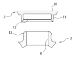
- FIG. 4 is a cross-sectional view showing the extraction port in the lower lid and the cylindrical portion in the upper lid.
- FIG. 4 is an explanatory diagram for explaining cross-sectional shapes of a shaft portion and a hole portion and an opening angle in a stable state;
- FIG. 4 is a cross-sectional view schematically showing an example of a mold for the lower lid for insert-molding the shaft portion into the lower lid.
- FIG. 4 is an exploded perspective view showing another embodiment of the present invention;
- FIG. 11 is a partial perspective view showing still another embodiment of the invention;
- FIG. 4 is a schematic partial view showing a state in which a pair of left and right shafts are fitted into corresponding holes;
- the cap according to the present invention is for opening and closing the opening of the container, and the opening/closing lid is connected by a hinge to the base portion integrated with the container. configured to open and close.
- the cap 1 attached to the tube container C is shown in FIG.
- fluid content such as liquid or gel
- the cap 1 shown here is composed of a lower lid 2 and an upper lid 3.
- the lower lid 2 is attached to the tube container C to form the mouth as a whole, and as shown in the cross-sectional view of FIG. 2 and the exploded perspective view of FIG.
- a top plate portion 5 is integrated, and an extraction port 6 as a mouth portion is formed in the center portion of the top plate portion 5 .
- the extraction port 6 is a cylindrical portion formed in the central portion of the top plate portion 5 so as to protrude in the axial direction.
- the tube container C has a body portion Bc for filling contents and a neck portion (opening portion) Oc integrally provided at the upper end thereof.
- a large cylindrical portion 7 fitted to the outside of the neck portion (opening) Oc of the tube container C and a small cylindrical portion 8 tightly fitted to the inside of the mouth portion are integrally formed. That is, the cap 1 is configured to be attached to the tube container C by fitting the large cylindrical portion 7 and the small cylindrical portion 8 to the neck portion Oc of the tube container C. As shown in FIG. In addition, the large cylindrical portion 7 can be configured to be fitted to the mouth/neck portion Oc of the tube container C in a state where it is retained by a screw or by a ring-shaped concave/convex portion.
- This lower lid 2 corresponds to the base portion in the present invention.
- the upper lid 3 corresponds to the opening/closing lid of the present invention, and is configured to cover the upper side of the lower lid 2 to cover the entirety thereof and to seal the extraction port 6 . That is, the upper lid 3 is integrally formed with a peripheral wall portion 9 having substantially the same diameter as the peripheral wall portion 4 of the lower lid 2 and a top plate portion 10 provided so as to close one end portion of the cylindrical peripheral wall portion 9. It is a so-called shallow cap-shaped or cup-shaped member. A low-height cylindrical portion 11 is formed in the central portion of the inner surface (lower surface) of the top plate portion 10 so as to be closely fitted to the outer peripheral side of the tip portion of the aforementioned cylindrical extraction port 6 .
- the outer peripheral portion of the upper end of the extraction port 6 is formed with a protruding line portion 12 that slightly protrudes toward the outer peripheral side, and the cross-sectional shape of that portion is directed outward. It has a hook shape.
- a protruding streak portion 13 forming a pair with the protruding streak portion 12 is formed on the inner peripheral portion of the tip end of the cylindrical portion 11 of the upper lid 3, and the cross-sectional shape of this portion is an inwardly hooked shape.
- the outer diameter of the ridge 12 in the extraction port 6 is slightly larger than the outer diameter of the ridge 13 in the cylindrical portion 11 of the upper lid 3.
- An arm portion 15 having a shape extending upward from a part of the peripheral wall portion 4 is provided on a part of the peripheral portion of the lower lid 2 . ing.
- the arm portion 15 has a columnar shape with a substantially rectangular cross section, and its height is substantially equal to the height of the upper lid 3.
- a side wall surface connected to the surface is an arcuate surface having substantially the same curvature as the outer peripheral surface of the lower lid 2 , that is, an arcuate surface having almost the same curvature as the outer peripheral surface of the upper lid 3 .
- a hole portion 16 is provided through a portion near the upper end of the arm portion 15, the hole portion 16 extending in a direction substantially parallel to the tangential line of the portion of the outer peripheral surface of the lower lid 2 where the arm portion 15 is provided.
- a cutout portion 17 is provided in a part of the outer peripheral portion of the upper lid 3 .
- the notch portion 17 is a portion of the lower lid 2 that accommodates the arm portion 15 and is a space portion having substantially the same shape as the arm portion 15 . Therefore, a portion of the peripheral wall portion 9 of the upper lid 3 is open in a rectangular shape with a width slightly larger than the width of the arm portion 15, and a portion of the peripheral portion of the top plate portion 10 is a cross section of the arm portion 15. It is vacant in almost the same shape as the shape.
- a shaft portion 18 facing in the same direction as the hole portion 16 is provided at a position of the arm portion 15 corresponding to the hole portion 16 . This cutout portion 17 corresponds to the accommodation portion in the present invention.
- the hole portion 16 and the shaft portion 18 have the same cross-sectional shape and are tightly fitted to each other.
- the same cross-sectional shape is a rectangular cross-sectional shape (preferably a regular polygonal shape such as a regular pentagonal shape or a regular hexagonal shape).
- it has an angular shape such as a regular hexagon, a regular pentagon, or a square with rounded corners in order to facilitate relative rotation accompanied by elastic deformation.
- FIG. 5 shows an example of a regular hexagon. Therefore, the shaft portion 18 has a length that is substantially the same as the width of the notch portion 17 (the width of the arm portion 15), and has the same cross-sectional shape (constant outer dimensions) over the entire longitudinal direction. ing.
- the stress associated with elastic deformation does not become torque for rotating the hole portion 16 (lower lid 2) and the shaft portion 18 (upper lid 3).
- the position becomes a so-called point of consideration.
- the stress associated with elastic deformation acts as a resistance force in the direction to prevent the rotation.
- the stress associated with elastic deformation acts as torque in the direction that promotes rotation.
- the hole portion 16 and the shaft portion 18 have a polygonal shape (preferably a polygonal shape with rounded corners) and are tightly fitted together, so that the hole portion 16 and the shaft portion 18 have a detent function. It is designed to play.
- the entire lower lid 2 including the arm portion 15 is integrally constructed, and specifically, is constructed of a synthetic resin material such as polypropylene (PP).
- the upper lid 3 is integrally constructed in its entirety including the shaft portion 18, and specifically, is constructed of a synthetic resin (for example, ABS resin) different from that of the lower lid 2.
- the lower lid 2 and the upper lid 3 are made of different resins (particularly, materials whose SP values are significantly different to some extent). This is a state in which the hole portion 16 and the shaft portion 18 are molded to have the same cross-sectional shape and are tightly fitted when the other is formed after one of the hole portion 16 and the shaft portion 18 is formed.
- An example of a manufacturing method therefor is an insert molding method or a two-color molding method.
- Examples of synthetic resins that can be used for the lower lid 2 and the upper lid 3 of the present invention include ABS resin, blended resin of ABS resin and polycarbonate (PC), polyacetal resin (POM), acrylic resin, nylon resin, and noryl resin. , polyamide-imide resin (PAI), polycarbonate resin (PC), polyethylene terephthalate resin (PET), polyethylene resin (PE), polypropylene resin (PP), polystyrene resin (PS), vinyl chloride, acrylonitrile styrene resin (SAN), etc. be.
- These synthetic resins are appropriately selected and used according to the molding order of the lower lid 2 and the upper lid 3 .
- FIG. 6 is a schematic cross-sectional view of a mold for explaining an example of insert molding.
- the upper lid 3 is molded in advance from ABS resin
- the upper lid 3 (especially the shaft portion 18) is set in the mold 19 for the lower lid 2
- the shaft portion 18 is attached to the lower lid 2.
- This is an example of inserting.
- the shaft portion 18, which has already been molded is arranged at the location where the arm portion 15 is to be molded. Therefore, by injecting a resin that does not weld to the upper lid 3 into the cavity 20 in this state, the lower lid 2 is molded, and the hole 16 that closely fits the shaft 18 and has the same cross-sectional shape is molded. can do.
- the cap 1 is attached to the tube container C by fitting the lower cover 2 to the mouth/neck portion Oc of the tube container C or the like.
- the cylindrical portion 11 provided on the inner surface (lower surface) of the upper lid 3 is tightly fitted into the extraction port 6 of the lower lid 2, and the extraction port 6 is sealed.
- the extraction port 6 is kept sealed.
- the corners of the shaft portion 18 are fitted into the corners of the hole portion 16 and are in a so-called stable state, the upper lid 3 is maintained in the closed state in this respect as well.
- the arm portion 15 of the lower lid 2 is accommodated inside the notch portion 17 of the upper lid 3 , and the side wall surface of the arm portion 15 on the outer peripheral side of the lower lid 2 is aligned with the upper lid 3 . It almost matches the outer peripheral surface. That is, the arm portion 15 or the hinge 14 does not protrude to the outer peripheral side of the cap 1, and the hinge 14 may be caught by peripheral members or other hinges 14 during handling or transportation of the cap 1 or the tube container C. It is possible to avoid or suppress the occurrence of scratches and the occurrence of troubles in handling, transportation, and the like.
- the upper lid 3 When the upper lid 3 is opened beyond this consideration point, the torque associated with the elastic deformation acts in the direction to open the upper lid 3. Therefore, the upper lid 3 can be opened without applying a particular force to the upper lid 3 or with a small force. can be opened further.
- the opening angle of the upper lid 3 becomes 60°, for example, and the corners of the shaft portion 18 are fitted into the corners of the hole portion 16, the elastic deformation of the hole portion 16 and the shaft portion 18 is eliminated and the opening is prevented. Since elastic deformation and associated resistance are generated in both the closing direction and the closing direction, the upper lid 3 is kept in this stable state, i. are maintained at a mating opening angle. Such stable states are, as shown in FIG. maintained at an angle.
- the upper cover 3 does not become an obstacle, and the handling convenience of the tube container C is improved. Further, when reaching each opening angle at which the upper lid 3 maintains the open state, the upper lid 3 rotates with torque due to restoration of the elastic deformation up to that point. That is, the force applied to the upper lid 3 changes, and then the upper lid 3 stabilizes at a predetermined opening angle. You can feel the opening action. As a result, the opening operation and closing operation of the upper cover 3 have a clear click feeling, and the operation feeling is good.
- FIG. 7 is an exploded perspective view for explaining another embodiment of the present invention.
- a shaft portion 18 is provided on the lower lid 2, and the shaft portion 18 is rotatable relative to the shaft portion 18.
- the upper lid 3 is provided with a hole portion 16 which is fitted in a closely contacting state. That is, the arm portion 15 is constituted by a pair of support plate portions 15a erected on the peripheral portion of the lower lid 2.
- the support plate portion 15a may be, for example, the same portion as the pair of plate-like portions remaining on both left and right sides after removing the central portion of the columnar arm portion 15 shown in FIGS.
- the shaft portion 18 has a configuration similar to that described in the above-described embodiment, and is arranged on the upper end side of the pair of support plate portions 15a so as to span between the support plate portions 15a. It is integrally formed with 15a.
- the notch portion 17 corresponding to the housing portion in the present invention is constituted by a pair of slits 17a formed in a part of the peripheral wall portion 9 of the upper lid 3 along the height direction.
- These slits 17a have substantially the same shape as the support plate portion 15a provided in the lower lid 2, and when the upper lid 3 is closed, the support plate portion 15a is almost completely accommodated inside the slits 17a.
- a hole rotatably fitted to the shaft portion 18 in close contact with the corner portion of the tongue-like portion (the sandwiched tongue-like portion) of the upper lid 3 partitioned by the slits 17a. 16 are formed.
- the cross-sectional shapes of the shaft portion 18 and the hole portion 16 are polygonal shapes similar to those described in the above-described embodiment. Further, the shaft portion 18 and the hole portion 16 can be fitted together at the manufacturing stage of the cap 1 by, for example, two-color molding or insert molding the lower lid 2 and the upper lid 3 .
- Other configurations of the cap 1 shown in FIG. 7 are the same as those in the above embodiment described with reference to FIGS. 1 to 5.
- the shaft portion 18 has the shape of a single shaft passing through the hole portion 16 formed in the arm portion 15 is shown. It may be a short shaft-like portion protruding toward the arm portion from the inner surfaces facing each other. Examples are shown in FIGS. 8 and 9.
- FIG. The shaft portion 18A shown here has the same structure as the shaft portion 18 shown in FIG. or a boss-shaped portion).
- the shaft portion 18A is integrated with the upper lid 3, and is molded together with the entire upper lid 3 when the upper lid 3 is made of synthetic resin.
- a hole portion 16A into which the shaft portion 18A is fitted is formed in the arm portion 15 in the same shape as the shaft portion 18A.
- the prefabricated upper lid 3 is set in a mold for molding the lower lid 2, and the lower mold 2 is insert-molded so that the shaft portion 18A is partially wrapped by the arm portion 15.
- a portion of the arm portion 15 occupied by the shaft portion 18A serves as the hole portion 16A. Therefore, as shown in FIG. 9, the shaft portion 18A and the hole portion 16A have the same cross-sectional shape and are tightly fitted to each other. It becomes the structure without a gap (clearance) between them.
- the elastic deformation force and the length of the shaft portion 18A are thought to determine the resistance (tightness) to the opening and closing operation of the top cover 3. Therefore, according to the cap 1 described above, the length of the shaft portion 18A is appropriately set. By doing so, the sense of moderation can be adjusted. In this case, since the outer diameter or outer dimensions of the shaft portion 18A are constant in the axial direction, the thrust force in the direction of pulling out the shaft portion 18A does not occur depending on the length of the shaft portion 18A, and the hinge 14 is thus secured. It is possible to prevent situations such as looseness, rattling, or falling off of the upper lid 3. - ⁇ The thickness (outer diameter) and corner roundness (curvature radius) of the shaft portion 18A and the length of the shaft portion 18A can be determined based on experiments or computer analysis.
- the present invention is not limited to the above-described embodiments, and can be implemented with appropriate modifications as necessary.
- the arm portion may be provided on the upper lid instead of the lower lid, and the notch portion as the storage portion may be provided on the lower lid instead of the upper lid.
- the shaft may be provided in the lower lid, and the hole into which it is fitted may be provided in the upper lid.
- the lower lid can be molded first and then the upper lid can be molded.
- the lower lid corresponding to the base portion of the present invention may be constructed as a part of the container instead of being a separate member from the container.
- the hinge or base part and the opening/closing lid of the present invention can also be manufactured by a 3D printer.
- One of the features of the present invention is that the hinge does not protrude to the outer peripheral side of the base portion or the opening/closing lid.
- the base portion in the present invention only needs to have a mouth portion, and for example, the entire portion may be open without having the above-described top plate portion. In that case, the engaging portion for keeping the opening/closing lid closed is provided on the outer peripheral portion of the base portion and the opening/closing lid.
- the shaft portion 18A and the hole portion 16A into which the shaft portion 18A is fitted are configured as a pair of short shafts and a hole as shown in FIGS. 3 or the lower lid 2) is not insert-molded, the upper lid 3 and the lower lid 2 are individually molded, and the shaft portion 18A and the hole portion 16A are fitted to each other to form the upper lid 3 and the lower lid 2. It may be assembled. Moreover, the fact that the shaft portion 18A may be provided in the lower lid 2 and the hole portion 16A may be provided in the upper lid 3 is the same as in the embodiment described with reference to FIG.
Landscapes
- Engineering & Computer Science (AREA)
- Mechanical Engineering (AREA)
- Closures For Containers (AREA)
Priority Applications (1)
| Application Number | Priority Date | Filing Date | Title |
|---|---|---|---|
| JP2023569173A JPWO2023119977A1 (https=) | 2021-12-23 | 2022-11-18 |
Applications Claiming Priority (2)
| Application Number | Priority Date | Filing Date | Title |
|---|---|---|---|
| JP2021-209031 | 2021-12-23 | ||
| JP2021209031 | 2021-12-23 |
Publications (1)
| Publication Number | Publication Date |
|---|---|
| WO2023119977A1 true WO2023119977A1 (ja) | 2023-06-29 |
Family
ID=86902227
Family Applications (1)
| Application Number | Title | Priority Date | Filing Date |
|---|---|---|---|
| PCT/JP2022/042816 Ceased WO2023119977A1 (ja) | 2021-12-23 | 2022-11-18 | キャップならびにそのキャップを備えた容器およびそのキャップを備えた製品ならびにキャップの製造方法 |
Country Status (2)
| Country | Link |
|---|---|
| JP (1) | JPWO2023119977A1 (https=) |
| WO (1) | WO2023119977A1 (https=) |
Cited By (1)
| Publication number | Priority date | Publication date | Assignee | Title |
|---|---|---|---|---|
| WO2025142144A1 (ja) * | 2023-12-27 | 2025-07-03 | 日本クロージャー株式会社 | ヒンジキャップ |
Citations (5)
| Publication number | Priority date | Publication date | Assignee | Title |
|---|---|---|---|---|
| JPS61156647U (https=) * | 1985-03-20 | 1986-09-29 | ||
| US5381935A (en) * | 1991-12-12 | 1995-01-17 | Tetra Laval Holdings & Finance S.A. | Closure unit for a container having a hinged construction, made of different materials and having a film which tears on first opening |
| JPH07137179A (ja) * | 1993-07-19 | 1995-05-30 | Xerox Corp | 2つの部材を移動可能に連結した組立体を製造する方法 |
| JP2011084288A (ja) * | 2009-10-14 | 2011-04-28 | Aska Company | キャップ付きチューブ容器 |
| JP2015203205A (ja) * | 2014-04-11 | 2015-11-16 | 株式会社協立 | 蝶番、蝶番の製造方法 |
-
2022
- 2022-11-18 JP JP2023569173A patent/JPWO2023119977A1/ja active Pending
- 2022-11-18 WO PCT/JP2022/042816 patent/WO2023119977A1/ja not_active Ceased
Patent Citations (5)
| Publication number | Priority date | Publication date | Assignee | Title |
|---|---|---|---|---|
| JPS61156647U (https=) * | 1985-03-20 | 1986-09-29 | ||
| US5381935A (en) * | 1991-12-12 | 1995-01-17 | Tetra Laval Holdings & Finance S.A. | Closure unit for a container having a hinged construction, made of different materials and having a film which tears on first opening |
| JPH07137179A (ja) * | 1993-07-19 | 1995-05-30 | Xerox Corp | 2つの部材を移動可能に連結した組立体を製造する方法 |
| JP2011084288A (ja) * | 2009-10-14 | 2011-04-28 | Aska Company | キャップ付きチューブ容器 |
| JP2015203205A (ja) * | 2014-04-11 | 2015-11-16 | 株式会社協立 | 蝶番、蝶番の製造方法 |
Cited By (1)
| Publication number | Priority date | Publication date | Assignee | Title |
|---|---|---|---|---|
| WO2025142144A1 (ja) * | 2023-12-27 | 2025-07-03 | 日本クロージャー株式会社 | ヒンジキャップ |
Also Published As
| Publication number | Publication date |
|---|---|
| JPWO2023119977A1 (https=) | 2023-06-29 |
Similar Documents
| Publication | Publication Date | Title |
|---|---|---|
| TWI605986B (zh) | Beverage container and its cap structure | |
| JP3423224B2 (ja) | 改良された密閉性を有する特にメークアップ用ケース形式とされたケース | |
| US8464731B1 (en) | Cosmetic compact with twistable lid | |
| US20030217761A1 (en) | Case for packaging a product | |
| US6170658B1 (en) | Folding data disc holder | |
| WO2023119977A1 (ja) | キャップならびにそのキャップを備えた容器およびそのキャップを備えた製品ならびにキャップの製造方法 | |
| CN112107103A (zh) | 具有改善的密封能力的化妆品容器 | |
| CN209346245U (zh) | 化妆品盒 | |
| JP3816062B2 (ja) | メークアップ製品用容器 | |
| JPH0937839A (ja) | 気密化粧料容器 | |
| KR102369204B1 (ko) | 내용물 저장 공간이 형성된 병뚜껑 | |
| JP4293661B2 (ja) | 液体化粧料の収納容器 | |
| KR200375840Y1 (ko) | 회전 개폐식 화장품 용기 | |
| JP6887448B2 (ja) | 化粧製品用のヒンジ連結アプリケータ、ならびに関連するパッケージングおよび塗布アセンブリ | |
| JP7053584B2 (ja) | ローラケース | |
| JPH1135060A (ja) | 容 器 | |
| JPH0617729Y2 (ja) | 容 器 | |
| KR101945415B1 (ko) | 화장품 용기 | |
| WO2008002079A1 (en) | Closure of vessel | |
| JPH0454937Y2 (https=) | ||
| JP3636793B2 (ja) | ワンタッチヒンジキャップ | |
| JPS635603Y2 (https=) | ||
| JPH031424Y2 (https=) | ||
| JP2014108788A (ja) | 蓋付き注出キャップ | |
| JP3499007B2 (ja) | 気密コンパクト容器 |
Legal Events
| Date | Code | Title | Description |
|---|---|---|---|
| 121 | Ep: the epo has been informed by wipo that ep was designated in this application |
Ref document number: 22910695 Country of ref document: EP Kind code of ref document: A1 |
|
| WWE | Wipo information: entry into national phase |
Ref document number: 2023569173 Country of ref document: JP |
|
| NENP | Non-entry into the national phase |
Ref country code: DE |
|
| 122 | Ep: pct application non-entry in european phase |
Ref document number: 22910695 Country of ref document: EP Kind code of ref document: A1 |