WO2023112554A1 - 乗物用シート - Google Patents
乗物用シート Download PDFInfo
- Publication number
- WO2023112554A1 WO2023112554A1 PCT/JP2022/041649 JP2022041649W WO2023112554A1 WO 2023112554 A1 WO2023112554 A1 WO 2023112554A1 JP 2022041649 W JP2022041649 W JP 2022041649W WO 2023112554 A1 WO2023112554 A1 WO 2023112554A1
- Authority
- WO
- WIPO (PCT)
- Prior art keywords
- seat
- sensor
- seat cushion
- control device
- vehicle
- Prior art date
- Legal status (The legal status is an assumption and is not a legal conclusion. Google has not performed a legal analysis and makes no representation as to the accuracy of the status listed.)
- Ceased
Links
Images













Classifications
-
- B—PERFORMING OPERATIONS; TRANSPORTING
- B60—VEHICLES IN GENERAL
- B60N—SEATS SPECIALLY ADAPTED FOR VEHICLES; VEHICLE PASSENGER ACCOMMODATION NOT OTHERWISE PROVIDED FOR
- B60N2/00—Seats specially adapted for vehicles; Arrangement or mounting of seats in vehicles
- B60N2/02—Seats specially adapted for vehicles; Arrangement or mounting of seats in vehicles the seat or part thereof being movable, e.g. adjustable
- B60N2/04—Seats specially adapted for vehicles; Arrangement or mounting of seats in vehicles the seat or part thereof being movable, e.g. adjustable the whole seat being movable
- B60N2/12—Seats specially adapted for vehicles; Arrangement or mounting of seats in vehicles the seat or part thereof being movable, e.g. adjustable the whole seat being movable slidable and tiltable
-
- A—HUMAN NECESSITIES
- A47—FURNITURE; DOMESTIC ARTICLES OR APPLIANCES; COFFEE MILLS; SPICE MILLS; SUCTION CLEANERS IN GENERAL
- A47C—CHAIRS; SOFAS; BEDS
- A47C7/00—Parts, details, or accessories of chairs or stools
- A47C7/62—Accessories for chairs
-
- B—PERFORMING OPERATIONS; TRANSPORTING
- B60—VEHICLES IN GENERAL
- B60N—SEATS SPECIALLY ADAPTED FOR VEHICLES; VEHICLE PASSENGER ACCOMMODATION NOT OTHERWISE PROVIDED FOR
- B60N2/00—Seats specially adapted for vehicles; Arrangement or mounting of seats in vehicles
- B60N2/02—Seats specially adapted for vehicles; Arrangement or mounting of seats in vehicles the seat or part thereof being movable, e.g. adjustable
- B60N2/0224—Non-manual adjustments, e.g. with electrical operation
- B60N2/02246—Electric motors therefor
-
- B—PERFORMING OPERATIONS; TRANSPORTING
- B60—VEHICLES IN GENERAL
- B60N—SEATS SPECIALLY ADAPTED FOR VEHICLES; VEHICLE PASSENGER ACCOMMODATION NOT OTHERWISE PROVIDED FOR
- B60N2/00—Seats specially adapted for vehicles; Arrangement or mounting of seats in vehicles
- B60N2/02—Seats specially adapted for vehicles; Arrangement or mounting of seats in vehicles the seat or part thereof being movable, e.g. adjustable
- B60N2/0224—Non-manual adjustments, e.g. with electrical operation
- B60N2/0244—Non-manual adjustments, e.g. with electrical operation with logic circuits
- B60N2/0268—Non-manual adjustments, e.g. with electrical operation with logic circuits using sensors or detectors for adapting the seat or seat part, e.g. to the position of an occupant
-
- B—PERFORMING OPERATIONS; TRANSPORTING
- B60—VEHICLES IN GENERAL
- B60N—SEATS SPECIALLY ADAPTED FOR VEHICLES; VEHICLE PASSENGER ACCOMMODATION NOT OTHERWISE PROVIDED FOR
- B60N2/00—Seats specially adapted for vehicles; Arrangement or mounting of seats in vehicles
- B60N2/02—Seats specially adapted for vehicles; Arrangement or mounting of seats in vehicles the seat or part thereof being movable, e.g. adjustable
- B60N2/0224—Non-manual adjustments, e.g. with electrical operation
- B60N2/0244—Non-manual adjustments, e.g. with electrical operation with logic circuits
- B60N2/0276—Non-manual adjustments, e.g. with electrical operation with logic circuits reaction to emergency situations, e.g. crash
-
- B—PERFORMING OPERATIONS; TRANSPORTING
- B60—VEHICLES IN GENERAL
- B60N—SEATS SPECIALLY ADAPTED FOR VEHICLES; VEHICLE PASSENGER ACCOMMODATION NOT OTHERWISE PROVIDED FOR
- B60N2/00—Seats specially adapted for vehicles; Arrangement or mounting of seats in vehicles
- B60N2/02—Seats specially adapted for vehicles; Arrangement or mounting of seats in vehicles the seat or part thereof being movable, e.g. adjustable
- B60N2/0224—Non-manual adjustments, e.g. with electrical operation
- B60N2/0244—Non-manual adjustments, e.g. with electrical operation with logic circuits
- B60N2/0278—Non-manual adjustments, e.g. with electrical operation with logic circuits using sensors external to the seat for measurements in relation to the seat adjustment, e.g. for identifying the presence of obstacles or the appropriateness of the occupants position
-
- B—PERFORMING OPERATIONS; TRANSPORTING
- B60—VEHICLES IN GENERAL
- B60N—SEATS SPECIALLY ADAPTED FOR VEHICLES; VEHICLE PASSENGER ACCOMMODATION NOT OTHERWISE PROVIDED FOR
- B60N2/00—Seats specially adapted for vehicles; Arrangement or mounting of seats in vehicles
- B60N2/02—Seats specially adapted for vehicles; Arrangement or mounting of seats in vehicles the seat or part thereof being movable, e.g. adjustable
- B60N2/04—Seats specially adapted for vehicles; Arrangement or mounting of seats in vehicles the seat or part thereof being movable, e.g. adjustable the whole seat being movable
- B60N2/06—Seats specially adapted for vehicles; Arrangement or mounting of seats in vehicles the seat or part thereof being movable, e.g. adjustable the whole seat being movable slidable
-
- B—PERFORMING OPERATIONS; TRANSPORTING
- B60—VEHICLES IN GENERAL
- B60N—SEATS SPECIALLY ADAPTED FOR VEHICLES; VEHICLE PASSENGER ACCOMMODATION NOT OTHERWISE PROVIDED FOR
- B60N2/00—Seats specially adapted for vehicles; Arrangement or mounting of seats in vehicles
- B60N2/02—Seats specially adapted for vehicles; Arrangement or mounting of seats in vehicles the seat or part thereof being movable, e.g. adjustable
- B60N2/04—Seats specially adapted for vehicles; Arrangement or mounting of seats in vehicles the seat or part thereof being movable, e.g. adjustable the whole seat being movable
- B60N2/14—Seats specially adapted for vehicles; Arrangement or mounting of seats in vehicles the seat or part thereof being movable, e.g. adjustable the whole seat being movable rotatable, e.g. to permit easy access
-
- B—PERFORMING OPERATIONS; TRANSPORTING
- B60—VEHICLES IN GENERAL
- B60N—SEATS SPECIALLY ADAPTED FOR VEHICLES; VEHICLE PASSENGER ACCOMMODATION NOT OTHERWISE PROVIDED FOR
- B60N2/00—Seats specially adapted for vehicles; Arrangement or mounting of seats in vehicles
- B60N2/56—Heating or ventilating devices
-
- B—PERFORMING OPERATIONS; TRANSPORTING
- B60—VEHICLES IN GENERAL
- B60N—SEATS SPECIALLY ADAPTED FOR VEHICLES; VEHICLE PASSENGER ACCOMMODATION NOT OTHERWISE PROVIDED FOR
- B60N2/00—Seats specially adapted for vehicles; Arrangement or mounting of seats in vehicles
- B60N2/64—Back-rests or cushions
-
- B—PERFORMING OPERATIONS; TRANSPORTING
- B60—VEHICLES IN GENERAL
- B60N—SEATS SPECIALLY ADAPTED FOR VEHICLES; VEHICLE PASSENGER ACCOMMODATION NOT OTHERWISE PROVIDED FOR
- B60N2/00—Seats specially adapted for vehicles; Arrangement or mounting of seats in vehicles
- B60N2/80—Head-rests
- B60N2/879—Head-rests with additional features not related to head-rest positioning, e.g. heating or cooling devices or loudspeakers
-
- B—PERFORMING OPERATIONS; TRANSPORTING
- B60—VEHICLES IN GENERAL
- B60N—SEATS SPECIALLY ADAPTED FOR VEHICLES; VEHICLE PASSENGER ACCOMMODATION NOT OTHERWISE PROVIDED FOR
- B60N2/00—Seats specially adapted for vehicles; Arrangement or mounting of seats in vehicles
- B60N2/90—Details or parts not otherwise provided for
-
- B—PERFORMING OPERATIONS; TRANSPORTING
- B60—VEHICLES IN GENERAL
- B60N—SEATS SPECIALLY ADAPTED FOR VEHICLES; VEHICLE PASSENGER ACCOMMODATION NOT OTHERWISE PROVIDED FOR
- B60N2210/00—Sensor types, e.g. for passenger detection systems or for controlling seats
- B60N2210/10—Field detection presence sensors
- B60N2210/12—Capacitive; Electric field
-
- B—PERFORMING OPERATIONS; TRANSPORTING
- B60—VEHICLES IN GENERAL
- B60N—SEATS SPECIALLY ADAPTED FOR VEHICLES; VEHICLE PASSENGER ACCOMMODATION NOT OTHERWISE PROVIDED FOR
- B60N2220/00—Computerised treatment of data for controlling of seats
- B60N2220/20—Computerised treatment of data for controlling of seats using a deterministic algorithm
Definitions
- the present invention relates to a vehicle seat.
- Patent Document 1 discloses a vehicle seat.
- the vehicle seat automatically moves so that the seat back is tilted backward. Therefore, the passenger can be relaxed.
- an object of the present invention is to eliminate the need for an occupant to confirm an object when moving a seat body in a vehicle seat.
- the present invention provides a vehicle seat (2) comprising a seat body (3), a drive device (6a) for moving the seat body, a drive device (6a) provided in the seat body, and an object and a sensor (7a) for detecting the approach and contact of the seat body by the drive device when the sensor detects the approach or contact of an object while the drive device is moving the seat body.
- control device controls the driving device when the sensor detects that the distance from the object is a preset first distance while the driving device is moving the seat body. After that, when the sensor detects that the distance to the object is a second distance shorter than the first distance, the movement of the seat body by the driving device is stopped. You may let
- the seat body can be stopped before the object contacts the seat body.
- control device reduces the moving speed of the seat body by the drive device when the sensor detects the approach of an object while the drive device is moving the seat body, and then The movement of the seat body by the driving device may be stopped when the contact of the object is detected by the sensor.
- the movement of the seat body can be continued until the seat body comes into contact with the object.
- the sheet body includes a skin (16) exposed to the outside and partially having a detection light hole (16a), the sensor is provided on the back side of the skin, and the skin The detection light is emitted to the outside through the detection light hole of the object, and the detection light is received when the detection light is reflected by the object and returned through the detection light hole, so that the approach of the object is detected. may be detected.
- the seat body includes a skin (16) exposed to the outside, the sensor is provided on the back side of the skin, emits detection radio waves to the outside of the skin through the skin, and the The approach of the object may be detected by receiving the detection radio wave when the detection radio wave is reflected by the object and returned via the epidermis.
- the sensors are arranged in a line and provided with a plurality of proximity detection bodies (17a) for respectively detecting approach of an object, and integrated with each of the plurality of proximity detection bodies to detect contact of an object. and a plurality of contact detectors (17b) that
- the senor holds a plurality of proximity detection bodies (17a) arranged in a row and each detects an approach of an object, and the plurality of proximity detection bodies (17b) collectively to detect contact of an object. and a contact detection body.
- the seat body includes a seat cushion (10), a seat back (11) rotatably provided at the rear portion of the seat cushion, and a headrest (12) provided at the upper portion of the seat back.
- the driving device (6a) moves the seat cushion in the longitudinal direction
- the sensor (7j) moves the lower portion of the seat cushion, the rear end portion of the seat cushion, and the back portion of the seat back. and at least one of the back of the headrest, and the control device controls when the sensor detects an approach or contact with an object while the drive device is moving the seat cushion rearward. , the rearward movement of the seatback by the driving device may be stopped.
- the seat body includes a seat cushion (10), a seat back (11) rotatably provided at the rear portion of the seat cushion, and a headrest (12) provided at the upper portion of the seat back.
- the driving device (6c) rotates the seat cushion
- the sensor (7b) rotates the corner of the seat cushion, the side of the seat cushion, the side of the seat back and the and the shoulder portion of the seat back
- the control device detects an approach or contact of an object by the sensor while the driving device is rotating the seat cushion. , the rotation of the seat cushion by the driving device may be stopped.
- the seat body includes a seat cushion (10), a seat back (11) rotatably provided at the rear portion of the seat cushion, and a headrest (12) provided at the upper portion of the seat back. and, the driving device (6b) rotates the seat back with respect to the seat cushion, and the sensor (7j) rotates the lower portion of the seat cushion, the rear end portion of the seat cushion and the seat.
- the control device is provided on at least one of the back of the back and the back of the headrest, and the control device detects an approach or contact of an object by the sensor when the driving device rotates the seatback rearward. When detected, rearward pivoting of the seat back by the drive device may be stopped.
- the seat body includes a seat cushion (10), a seat back (11) rotatably provided at the rear portion of the seat cushion, and a headrest (12) provided at the upper portion of the seat back.
- the driving device moves the seat cushion in the left-right direction
- the sensor (7c) moves the lower part of the seat cushion, the side edge of the seat cushion, the side edge of the seat back and the and at least one of the side ends of the headrest
- the control device detects the approach or contact of an object by the sensor while the driving device is moving the seat cushion in the left-right direction. At this time, the lateral movement of the seat cushion by the driving device may be stopped.
- Japanese Patent Application Laid-Open No. 2004-097654 discloses a seat with an audio output device. According to the seat, the mounting structure of the audio output device can be simplified.
- the sound output device diffuses the sound inside the vehicle compartment. Therefore, the voice is transmitted even to passengers who do not need the voice. Therefore, in a vehicle, it is a problem to transmit information to the passengers who need the information and not to transmit the information to the passengers who do not need the information.
- the present invention provides a notification system for a vehicle, which includes an audio output device (112) provided in the vehicle for outputting information by audio, and an audio output side of the audio output device. a direction changing device (115) for changing the output direction of the voice of the voice output device; and a control device (118) for controlling said redirection device such that the output direction of the seat is toward said particular seat.
- control device controls the direction changing device so that when the audio output device outputs information about driving by voice, the output direction of the audio from the audio output device is the direction of the driver's seat.
- information regarding driving can be reliably transmitted to the passenger present in the driver's seat.
- a storage device (124) in which information indicating the type of voice and identification information of the seat are associated and stored, and the control device controls the voice based on the information stored in the storage device.
- the type of information output by the output device is determined, the identification information associated with the information indicating the type in the storage device is determined, and the output direction of the sound of the audio output device is the seat corresponding to the identification information.
- the direction changing device may be controlled to be the direction.
- the audio output device may be provided at the door (105) of the vehicle.
- the audio output device may be provided on the seat (102) of the vehicle.
- information can be reliably transmitted to the passenger present in the seat.
- the audio output device may be provided on the seat back (102B) of the seat.
- information can be transmitted more reliably to the passenger present in the seat.
- the audio output device may be provided on the headrest (102C) of the seat.
- information can be transmitted more reliably to the passenger present in the seat.
- the work for electrically connecting the audio output device and the direction changing device to the control device can be easily performed.
- the present invention is a vehicle notification system comprising a seat (125) provided in a vehicle, a partition (126) surrounding said seat, and a support device supported by said partition. (127), a plurality of audio output devices (128A, 128B) supported by the support device, and provided on the audio output sides of the plurality of audio output devices, respectively, supported by the support device, and the plurality of a plurality of direction changing devices (129A, 129B) for respectively changing the output direction of the voice of the voice output device; a control device (118) for controlling the plurality of direction changing devices so that the direction of sound output from the plurality of sound output devices is the direction of the head of the occupant present on the seat.
- the mounting structure of the plurality of sound output devices and the plurality of direction change devices can be reduced in the number of parts and in size. can do.
- the present invention is a vehicle notification system, which is installed on a vehicle floor (101) so that the transmission direction of vibration sound from the floor is not the direction of the vehicle seat.
- the passenger's discomfort can be suppressed.
- the present invention provides a vehicle notification system, which is provided on a seating surface of a seat back (104B) of a vehicle seat (104), and an ultrasonic wave output device (133A) for outputting ultrasonic waves. ), a direction changing device (134A) provided on the output side of the ultrasonic wave of the ultrasonic output device for changing the output of the ultrasonic wave of the ultrasonic output device, and the output direction of the ultrasonic wave of the ultrasonic output device a control device (118) for controlling the reorienting device such that the direction of the body part of the occupant residing in the seat.
- Japanese Patent Application Laid-Open No. 2022-000293 discloses a seat structure. According to the seat structure, virus droplet infection can be suppressed.
- the present invention provides a notification system for a vehicle, comprising notification devices (218, 219) for notifying information, a sensor (222A) provided in the vehicle for detecting viruses, and the and a control device (220) for notifying the notification device of information on detection of a virus when the sensor detects the virus.
- the senor may be provided on the steering wheel (213) of the vehicle.
- the senor may be provided on the instrument panel (214) of the vehicle.
- the senor may be provided on the door trim (227) of the vehicle.
- the seat includes a seat cushion (207), a seat back (208) rotatably provided at the rear portion of the seat cushion, and a headrest (209) provided above the seat back.
- the sensor may be provided on the headrest.
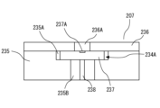
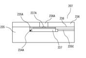
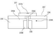
- the sheet includes an outer skin (236) that is exposed to the outside and has a virus detection hole (236A) in a part thereof, and the sensor is provided on the back side of the outer skin. A virus that moves from the front side to the back side of the epidermis through the virus detection hole may be detected.
- the virus can be reliably detected even if the sensor is provided on the back side of the epidermis.
- a duct (239) provided in the vehicle and having an inlet (239A) and an outlet (239B); a blower (241) forming a flow, wherein the sensor is provided between the inlet and the outlet inside the duct and may detect viruses in the air flowing through the duct.
- the virus can be detected more reliably.
- a filter (242) may be provided inside the duct between the sensor and the outflow port to trap viruses.
- the senor may be provided detachably with respect to the duct.
- a photocatalyst (244A) that is provided adjacent to the sensor and kills viruses may be provided.
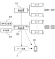
- control device may notify the mobile terminal (221) existing outside the vehicle of information regarding virus detection.
- control device may notify the mobile terminal of information regarding virus detection via a server device (S) located outside the vehicle.
- the present invention provides a vehicle notification system comprising notification devices (218, 219) provided in a vehicle for notifying information, and an inlet (239A) provided in the vehicle.
- a duct (239) having an outlet (239B), a blower (241) provided in the duct and forming an air flow from the inlet to the outlet, arranged side by side inside the duct.
- a plurality of sensors (243C to 243E) provided to detect viruses different from each other, and a control device (220) for notifying the notification device of information on virus detection when any one of the plurality of sensors detects a virus. ), and
- Japanese Patent Application Laid-Open No. 2021-172729 discloses materials for vehicle interior members. With this material, an interior member with excellent scratch resistance can be realized.
- the present invention provides an interior member for a vehicle, which includes a structure (325A) provided in the vehicle and having a surface at least partially formed of a self-repairing resin. .
- the state of the design surface of the interior member can be maintained.
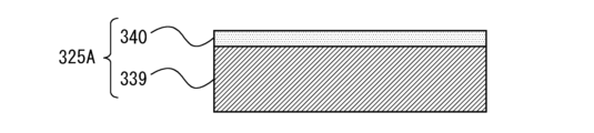
- the structure has a substrate (339) made of a resin and a surface made of a self-healing resin different from the resin, and a coated body (340) covering the surface of the substrate. ) and .
- the state of the design surface of the interior member can be maintained while realizing the strength necessary for the interior member in the base body.
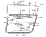
- the structure may be provided in a door trim (329) provided on the passenger compartment side of the door (305) of the vehicle.
- the structure may be provided around the door handle (330) in the door trim.
- the structure may be provided around the switch (333) in the door trim.
- the structure may be provided under the door trim.
- the structure may be provided above the door trim.
- the armrest (332) of the door trim may be provided on the armrest (332) of the door trim.
- the door pocket (334) in the door trim may be provided in the door pocket (334) in the door trim.
- the instrument panel (318) of the vehicle may be provided on the instrument panel (318) of the vehicle.
- the structure may be provided on the steering wheel (317) of the vehicle.
- the structure may be provided on the floor (301) of the vehicle.
- the structure may be provided on the pillars (302, 303) of the vehicle.
- the structure may be provided in the center console (319) of the vehicle.
- the structure may be provided in the shift lever (320) of the vehicle.
- the structure may be provided on the seat (306) of the vehicle.
- Japanese Patent Laying-Open No. 2017-178129 discloses a vehicle seat provided with a seat heater.
- the seat heater includes a heater unit, an air blower arranged at a portion corresponding to the heater unit, and a control device for controlling outputs of the heater unit and the air blower.
- a seat cushion of a vehicle seat and a pad material of a seat back have a plurality of ventilation holes formed on the surface and a ventilation path communicating with the ventilation holes.
- the seat cushion and seat back are configured to blow air from the seat surface toward the occupant through the ventilation holes and the upholstery by the operation of a blower.
- Japanese Patent Application Laid-Open No. 2020-195429 discloses a seat capable of efficiently delivering fragrance to a seated person.
- the seat includes an air outlet and an air inlet arranged in the upper part of the seat including the seat back and the headrest, at least one fan forming an air flow from the air outlet to the air inlet on the front side of the upper part of the seat, and blown out from the air outlet. and an air freshener for adding fragrance to the air.
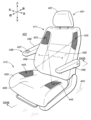
- one aspect of the present invention is a seat lower part (412) including a seat cushion (405), and a seat back (406) and a headrest (407) above the seat cushion.
- air vents (425, 445) provided in the upper and lower seat portions, respectively; and an air blower for blowing air from one of the vents. (419), and an air intake (419) for sucking air from the other of the vents, wherein the air supply direction of the air sent from one of the vents is directed toward the vent on the side of the air intake. ing.
- the one and the other of the vents are opposed to each other.
- At least one of the vents is provided with a louver (463) for adjusting the direction of air flow.
- the direction of air flow in the vent can be adjusted by the louver. Therefore, it is possible to favorably generate an airflow from one side of the vent to the other.
- the vents provided in the upper part of the seat are located on left and right sides of the upper front surface of the seat back, and the vents provided in the lower part of the seat are located in front of the upper surface of the seat cushion. located in the department.
- the vent holes are provided on one of the left and right sides of the upper part of the seat and the other of the left and right sides of the lower part of the seat, respectively, and the air flow (F1 -F4) is generated.
- a pair of left and right air vents are provided in the upper portion of the seat and the lower portion of the seat, respectively, so that diagonal airflows (F1, F2, F3, F4) are generated when viewed from the front. .
- the air vents are provided on one of the left and right sides of the upper portion of the seat and one of the left and right sides of the lower portion of the seat, respectively, and the airflow (F11- F14) is generated.
- air currents are generated along the sides of the seated person, so it is possible to effectively blow air to the seated person.
- a pair of left and right air vents are provided in the upper portion of the seat and the lower portion of the seat, respectively, so that airflows (F11, F12, F13, F14) parallel to the center line when viewed from the front are generated. generated.
- the seat lower portion preferably includes an ottoman (459).
- an airflow can be generated near the legs of the seated person.
- a fan (419) provided for each of the vents and a control device (450) for controlling the driving of the fan, the control device controlling the flow of air from the corresponding vent. Controls the driving of the fan for delivery and suction.
- a temperature control unit (455) that performs at least one of heating and cooling of the delivered air.
- the temperature control unit preferably includes a heater (421) provided above the seat for warming the air sent out from the vent.
- warm air can be sent downward from the upper part of the seat. Thereby, it is possible to prevent the warmed air from staying in the upper part of the room. Therefore, heating efficiency can be improved.
- the temperature control unit preferably includes a cooler (441) provided under the seat for cooling the air sent out from the vent.
- cold air can be sent upward from the lower part of the seat. This can prevent cold air from staying in the lower part of the room. Therefore, cooling efficiency can be improved.
- a seat occupant sensor (470) that detects the state of a seated occupant
- a controller (450) for controlling at least one drive.
- air can be blown according to the state of the seated person.
- a seat state sensor (462) that detects the state of at least one of the upper portion of the seat and the lower portion of the seat, and based on the detection result of the seat state sensor, the air blower and the air intake and a controller (450) that controls driving of at least one of the temperature control units.
- air can be blown according to the state of the seat.
- the present invention provides a vehicle seat (2) comprising a seat body (3), a drive device (6a) for moving the seat body, and a sensor provided on the seat body for detecting the approach or contact of an object. (7a) and a control device (9) that stops movement of the seat body by the drive device when the sensor detects the approach or contact of an object while the drive device is moving the seat body. ), and
- control device controls the driving device when the sensor detects that the distance from the object is a preset first distance while the driving device is moving the seat body. After that, when the sensor detects that the distance to the object is a second distance shorter than the first distance, the movement of the seat body by the driving device is stopped. You may let
- the seat body can be stopped before the object contacts the seat body.
- control device reduces the moving speed of the seat body by the drive device when the sensor detects the approach of an object while the drive device is moving the seat body, and then The movement of the seat body by the driving device may be stopped when the contact of the object is detected by the sensor.
- the movement of the seat body can be continued until the seat body comes into contact with the object.
- the sheet body includes a skin (16) exposed to the outside and partially having a detection light hole (16a), the sensor is provided on the back side of the skin, and the skin The detection light is emitted to the outside through the detection light hole of the object, and the detection light is received when the detection light is reflected by the object and returned through the detection light hole, so that the approach of the object is detected. may be detected.
- the seat body includes a skin (16) exposed to the outside, the sensor is provided on the back side of the skin, emits detection radio waves to the outside of the skin through the skin, and the The approach of the object may be detected by receiving the detection radio wave when the detection radio wave is reflected by the object and returned via the epidermis.
- the sensors are arranged in a line and provided with a plurality of proximity detection bodies (17a) for respectively detecting approach of an object, and integrated with each of the plurality of proximity detection bodies to detect contact of an object. and a plurality of contact detectors (17b) that
- the senor holds a plurality of proximity detection bodies (17a) arranged in a row and each detects an approach of an object, and the plurality of proximity detection bodies (17b) collectively to detect contact of an object. and a contact detection body.
- the seat body includes a seat cushion (10), a seat back (11) rotatably provided at the rear portion of the seat cushion, and a headrest (12) provided at the upper portion of the seat back.
- the driving device (6a) moves the seat cushion in the longitudinal direction
- the sensor (7j) moves the lower portion of the seat cushion, the rear end portion of the seat cushion, and the back portion of the seat back. and at least one of the back of the headrest, and the control device controls when the sensor detects an approach or contact with an object while the drive device is moving the seat cushion rearward. , the rearward movement of the seatback by the driving device may be stopped.
- the seat body includes a seat cushion (10), a seat back (11) rotatably provided at the rear portion of the seat cushion, and a headrest (12) provided at the upper portion of the seat back.
- the driving device (6c) rotates the seat cushion
- the sensor (7b) rotates the corner of the seat cushion, the side of the seat cushion, the side of the seat back and the and the shoulder portion of the seat back
- the control device detects an approach or contact of an object by the sensor while the driving device is rotating the seat cushion. , the rotation of the seat cushion by the driving device may be stopped.
- the seat body includes a seat cushion (10), a seat back (11) rotatably provided at the rear portion of the seat cushion, and a headrest (12) provided at the upper portion of the seat back. and, the driving device (6b) rotates the seat back with respect to the seat cushion, and the sensor (7j) rotates the lower portion of the seat cushion, the rear end portion of the seat cushion and the seat.
- the control device is provided on at least one of the back of the back and the back of the headrest, and the control device detects an approach or contact of an object by the sensor when the driving device rotates the seatback rearward. When detected, rearward pivoting of the seat back by the drive device may be stopped.
- the seat body includes a seat cushion (10), a seat back (11) rotatably provided at the rear portion of the seat cushion, and a headrest (12) provided at the upper portion of the seat back.
- the driving device moves the seat cushion in the left-right direction
- the sensor (7c) moves the lower part of the seat cushion, the side edge of the seat cushion, the side edge of the seat back and the and at least one of the side ends of the headrest
- the control device detects the approach or contact of an object by the sensor while the driving device is moving the seat cushion in the left-right direction. At this time, the lateral movement of the seat cushion by the driving device may be stopped.
- a notification system for a vehicle comprising: an audio output device (112) provided on a vehicle for outputting information by audio; A direction changing device (115) for changing direction, and when said voice output device outputs information directed to the occupant of a specific seat by voice, the voice output direction of said voice output device becomes the direction of said specific seat. a control device (118) for controlling said redirection device so as to.
- control device controls the direction changing device so that when the audio output device outputs information about driving by voice, the output direction of the audio from the audio output device is the direction of the driver's seat.
- information regarding driving can be reliably transmitted to the passenger present in the driver's seat.
- a storage device (124) in which information indicating the type of voice and identification information of the seat are associated and stored, and the control device controls the voice based on the information stored in the storage device.
- the type of information output by the output device is determined, the identification information associated with the information indicating the type in the storage device is determined, and the output direction of the sound of the audio output device is the seat corresponding to the identification information.
- the direction changing device may be controlled to be the direction.
- the audio output device may be provided at the door (105) of the vehicle.
- the audio output device may be provided on the seat (104) of the vehicle.
- information can be reliably transmitted to the passenger present in the seat.
- the audio output device may be provided on the seat back (104B) of the seat.
- information can be transmitted more reliably to the passenger present in the seat.
- the audio output device may be provided on the headrest (104C) of the seat.
- information can be transmitted more reliably to the passenger present in the seat.
- the work for electrically connecting the audio output device and the direction changing device to the control device can be easily performed.
- the present invention is a vehicle notification system comprising a seat (125) provided in a vehicle, a partition (126) surrounding said seat, and a support device supported by said partition. (127), a plurality of audio output devices (128A, 128B) supported by the support device, and provided on the audio output sides of the plurality of audio output devices, respectively, supported by the support device, and the plurality of a plurality of direction changing devices (129A, 129B) for respectively changing the output direction of the voice of the voice output device; a control device (118) for controlling the plurality of direction changing devices so that the direction of sound output from the plurality of sound output devices is the direction of the head of the occupant present on the seat.
- the mounting structure of the plurality of sound output devices and the plurality of direction change devices can be reduced in the number of parts and in size. can do.
- the present invention is a vehicle notification system, which is installed on a vehicle floor (101) so that the transmission direction of vibration sound from the floor is not the direction of the vehicle seat.
- the passenger's discomfort can be suppressed.
- the present invention provides a vehicle notification system, which is provided on a seating surface of a seat back (104B) of a vehicle seat (104), and an ultrasonic wave output device (133A) for outputting ultrasonic waves. ), a direction changing device (134A) provided on the output side of the ultrasonic wave of the ultrasonic output device for changing the output of the ultrasonic wave of the ultrasonic output device, and the output direction of the ultrasonic wave of the ultrasonic output device a control device (118) for controlling the reorienting device such that the direction of the body part of the occupant residing in the seat.
- a notification system for a vehicle comprising notification devices (218, 219) provided in a vehicle for notifying information, a sensor (222A) provided in the vehicle for detecting a virus, and when the sensor detects a virus. and a control device (220) for notifying the notification device of information on virus detection.
- the senor may be provided on the steering wheel (213) of the vehicle.
- the senor may be provided on the instrument panel (214) of the vehicle.
- the senor may be provided on the door trim (227) of the vehicle.
- the seat includes a seat cushion (207), a seat back (208) rotatably provided at the rear portion of the seat cushion, and a headrest (209) provided above the seat back.
- the sensor may be provided on the headrest.
- the sheet includes an outer skin (236) that is exposed to the outside and has a virus detection hole (236A) in a part thereof, and the sensor is provided on the back side of the outer skin. A virus that moves from the front side to the back side of the epidermis through the virus detection hole may be detected.
- the virus can be reliably detected even if the sensor is provided on the back side of the epidermis.
- a duct (239) provided in the vehicle and having an inlet (239A) and an outlet (239B); a blower (241) forming a flow, wherein the sensor is provided between the inlet and the outlet inside the duct and may detect viruses in the air flowing through the duct.
- the virus can be detected more reliably.
- a filter (242) may be provided inside the duct between the sensor and the outflow port to trap viruses.
- the senor may be provided detachably with respect to the duct.
- a photocatalyst (244A) that is provided adjacent to the sensor and kills viruses may be provided.
- control device may notify the mobile terminal (221) existing outside the vehicle of information regarding virus detection.
- control device may notify the mobile terminal of information regarding virus detection via a server device (S) located outside the vehicle.
- the present invention provides a vehicle notification system comprising notification devices (218, 219) provided in a vehicle for notifying information, and an inlet (239A) provided in the vehicle.
- a duct (239) having an outlet (239B), a blower (241) provided in the duct and forming an air flow from the inlet to the outlet, arranged side by side inside the duct.
- a plurality of sensors (243C to 243E) provided to detect viruses different from each other, and a control device (220) for notifying the notification device of information on virus detection when any one of the plurality of sensors detects a virus. ), and
- the state of the design surface of the interior member can be maintained.
- the structure has a substrate (339) made of a resin and a surface made of a self-healing resin different from the resin, and a coated body (340) covering the surface of the substrate. ) and .
- the state of the design surface of the interior member can be maintained while realizing the strength necessary for the interior member in the base body.
- the structure may be provided in a door trim (329) provided on the passenger compartment side of the door (305) of the vehicle.
- the structure may be provided around the door handle (330) in the door trim.
- the structure may be provided around the switch (333) in the door trim.
- the structure may be provided under the door trim.
- the structure may be provided above the door trim.
- the armrest (332) of the door trim may be provided on the armrest (332) of the door trim.
- the door pocket (334) in the door trim may be provided in the door pocket (334) in the door trim.
- the instrument panel (318) of the vehicle may be provided on the instrument panel (318) of the vehicle.
- the structure may be provided on the steering wheel (317) of the vehicle.
- the structure may be provided on the floor (301) of the vehicle.
- the structure may be provided on the pillars (302, 303) of the vehicle.
- the structure may be provided in the center console (319) of the vehicle.
- the structure may be provided in the shift lever (320) of the vehicle.
- the structure may be provided on the seat (306) of the vehicle.
- a seat comprising a seat lower portion including a seat cushion and an upper portion of the seat above the seat cushion and including a seat back and a headrest, wherein ventilation holes are provided in the seat upper portion and the seat lower portion, respectively.
- an air blower for blowing air from one of the vents; and an air intake for sucking air from the other of the vents, wherein the direction of the air blown from one of the vents is that of the air blower. facing the vent on the side.
- the one and the other of the vents are opposed to each other.
- At least one of the vents is provided with a louver for adjusting the direction of air flow.
- the direction of air flow in the vent can be adjusted by the louver. Therefore, it is possible to favorably generate an airflow from one side of the vent to the other.
- the vents provided in the upper part of the seat are located on left and right sides of the upper front surface of the seat back, and the vents provided in the lower part of the seat are located in front of the upper surface of the seat cushion. located in the department.
- the air vents are provided on one of the left and right sides of the upper portion of the seat and the other of the left and right sides of the lower portion of the seat, respectively, and generate an airflow in a direction that intersects the center line when viewed from the front.
- a pair of left and right air vents are provided in the upper portion of the seat and the lower portion of the seat, respectively, so that diagonal airflows are generated when viewed from the front.
- the air vents are provided on one of the left and right sides of the upper portion of the seat and one of the left and right sides of the lower portion of the seat, respectively, so that an airflow is generated in a direction parallel to the center line when viewed from the front. be.
- air currents are generated along the sides of the seated person, so it is possible to effectively blow air to the seated person.
- a pair of left and right air vents are provided in the upper portion of the seat and the lower portion of the seat, respectively, to generate an airflow parallel to the center line in a front view.
- the seat lower portion preferably includes an ottoman.
- an airflow can be generated near the legs of the seated person.
- a fan provided for each of the vents, and a control device for controlling the driving of the fan, wherein the control device sends out and sucks air from the corresponding vent. , to control the driving of the fan.
- the above aspect preferably includes a temperature control unit that performs at least one of heating and cooling of the air that is sent out.
- the temperature control unit preferably includes a heater provided above the seat for warming the air sent out from the vent.
- warm air can be sent downward from the upper part of the seat. Thereby, it is possible to prevent the warmed air from staying in the upper part of the room. Therefore, heating efficiency can be improved.
- the temperature control unit is provided under the seat and includes a cooler for cooling the air sent out from the vent.
- cold air can be sent upward from the lower part of the seat. This can prevent cold air from staying in the lower part of the room. Therefore, cooling efficiency can be improved.
- a seat occupant sensor for detecting a state of a seat occupant, and at least one of the air blower, the air intake, and the temperature control unit is controlled based on the detection result of the seat occupant sensor. and a control device for controlling the drive.
- air can be blown according to the state of the seated person.
- a seat state sensor detects the state of at least one of the upper portion of the seat and the lower portion of the seat, and the air blower, the air intake, and and a control device that controls driving of at least one of the temperature control units.
- air can be blown according to the state of the seat.
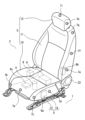
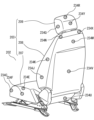
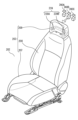
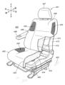
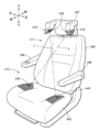
- FIG. 1 is a perspective view of a front portion of a vehicle seat according to a first embodiment
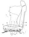
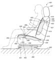
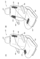
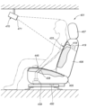
- FIG. Perspective view of the rear of the vehicle seat Longitudinal sectional view of a vehicle seat
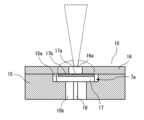
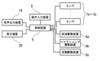
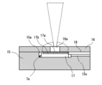
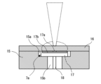
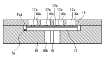
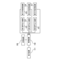
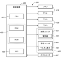
- Cross-sectional view of a specific example of a sensor Block diagram for explaining the control target of the control device Cross-sectional view of the first modification of the sensor Cross-sectional view of a second modification of the sensor Cross-sectional view of the third modification of the sensor Cross-sectional view of a fourth modification of the sensor
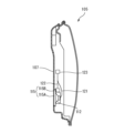
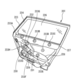
- FIG. 1 Front view of the driver's side door Perspective view of the front of the seat Longitudinal view of structure
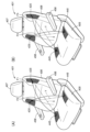
- Side view of the seat according to the ninth embodiment Block diagram of the airflow generation unit (A) Perspective view showing airflow during cooling process and (B) airflow during heating process (A) Front view showing airflow during cooling process and (B) airflow during heating process A perspective view showing a modification of the seat according to the ninth embodiment.
- FIG. 9 Front view showing a modification of the seat according to the ninth embodiment
- FIG. 10 Front view showing a modification of the seat according to the ninth embodiment
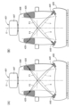
- FIG. 10 It is a modified example of the seat according to the ninth embodiment, and (A) an example in which the seat back and the seat cushion are each provided with vent holes on the left and right sides, and (B) an example in which the seat cushion Example when ventilation holes are provided
- This is a modification of the seat according to the ninth embodiment, and is a perspective view showing (A) airflow during cooling processing and (B) airflow during heating processing when airflow parallel to the center line of the seat is generated.
- a floor 1 forms the floor of the vehicle.
- a seat 2 is provided on the floor 1 .
- the seat 2 includes a seat body 3, a rotating device 4, a sliding device 5, a plurality of driving devices 6a-6c, a plurality of sensors 7a-7n, an operation input device 8, and a control device 9.
- the seat body 3 includes a seat cushion 10, a seat back 11 and a headrest 12.
- the seat cushion 10 has a seat surface.
- the seat back 11 is provided at the rear end portion of the seat cushion 10 .
- the headrest 12 is provided at the upper end portion of the seat back 11 .
- the slide device 5 includes a pair of lower rails 13 and a pair of upper rails 14.
- the pair of lower rails 13 are provided on the floor 1 with their longitudinal directions extending in the front-rear direction of the floor 1 .
- a pair of upper rails 14 are provided on the lower surface of the seat cushion 10 with their longitudinal directions extending in the front-rear direction of the floor 1 .
- the pair of upper rails 14 are guided in the front-rear direction by the pair of lower rails 13, respectively.
- the rotating device 4 is provided between the upper rail 14 of the sliding device 5 and the seat cushion 10 .
- the rotating device 4 supports the seat cushion 10 so as to be rotatable about the vertical axis with respect to the left and right upper rails 14 .
- the seat back 11 is rotatably supported by the seat cushion 10 via the reclining device 22 .
- the reclining device 22 supports the seat back 11 at an arbitrary angle with respect to the seat cushion 10 .
- the front-rear driving device 6a is provided under the seat cushion 10.
- the longitudinal drive device 6a drives the slide device 5 to drive the seat cushion 10 in the longitudinal direction.
- the front-rear driving device 6 a is provided between the lower rail 13 and the upper rail 14 and moves the upper rail 14 with respect to the lower rail 13 .
- the longitudinal drive 6a may be, for example, a ball screw mechanism driven by an electric motor.
- the reclining drive device 6b has an electric motor and is provided on the seatback 11.
- the reclining drive device 6b drives the reclining device 22 to rotate the seat back 11 with respect to the seat cushion 10.
- the rotation driving device 6c has an electric motor and is provided under the seat cushion 10.
- the rotation drive device 6 c drives the rotation device 4 to rotate the seat cushion 10 with respect to the pair of upper rails 14 .
- the sensor 7a is provided in the central portion of the front end face of the seat cushion 10. As shown in FIG.
- the sensor 7b is provided at the right corner of the front end surface of the seat cushion 10. As shown in FIG.
- the sensor 7c is provided at the left corner of the front end surface of the seat cushion 10.
- the sensor 7 d is provided on the lower left side surface of the seat cushion 10 .
- the sensor 7e is provided below the left side surface of the seat back 11 .
- the sensor 7f is provided in the central portion of the left side surface of the seatback 11. As shown in FIG.
- the sensor 7g is provided on the left shoulder of the seat back 11.
- the sensor 7h is provided in the central portion of the left side surface of the headrest 12. As shown in FIG.
- the sensor 7i is provided in the central portion of the top surface of the headrest 12 .
- the sensor 7j is provided at the central portion of the rear end surface of the seat cushion 10. As shown in FIG. The sensor 7k is provided in the central portion of the back surface of the seat back 11. As shown in FIG. The sensor 7 l is provided on the upper part of the back surface of the seat back 11 . The sensor 7m is provided in the central portion of the back surface of the headrest 12 .
- the sensor 7n is provided on the front portion of the lower surface of the seat cushion 10. As shown in FIG. 3, the sensor 7o is provided on the lower surface of the seat cushion 10 toward the rear. The sensor 7p is provided at the rear portion of the lower surface of the seat cushion 10. As shown in FIG.
- the operation input device 8 is provided on the left side surface of the seat cushion 10. As shown in FIG. 1 to 3, the operation input device 8 is provided on the left side surface of the seat cushion 10. As shown in FIG. 1 to 3, the operation input device 8 is provided on the left side surface of the seat cushion 10. As shown in FIG. 1 to 3, the operation input device 8 is provided on the left side surface of the seat cushion 10.
- the control device 9 is provided under the seat cushion 10 .
- the control device 9 is electrically connected to the plurality of driving devices 6a to 6c, the plurality of sensors 7a to 7n, and the operation input device 8.
- FIG. Sensors 7a-7n detect the approach and contact of objects.
- the passenger operates the operation input device 8 to operate one of the plurality of drive devices 6a to 6c.
- the seat body 3 starts moving corresponding to the operation of one of the plurality of driving devices 6a to 6c.
- the plurality of sensors 7a to 7p start detection operations.
- the control device 9 stops movement of the seat body 3 by any one of the plurality of driving devices 6a to 6c.
- the control device 9 reduces the moving speed of the sheet body 3 by the driving devices 6a to 6c.
- the control device 9 controls any one of the plurality of driving devices 6a to 6c.
- the movement of the seat body 3 is stopped.
- the first distance and the second distance are appropriately set.
- the first distance is set to 100mm.
- the second distance is set to 50 mm.
- the operation input device 8 is provided with a switch (not shown) corresponding to one of the plurality of driving devices 6a to 6c.
- the control device 9 selects at least one of the plurality of drive devices 6a to 6c.
- the control device 9 sets the driving amount per unit time for the corresponding driving devices 6a to 6c based on the minimum value of the distance to the object detected by the plurality of sensors 7j to 7p. 6c are driven to move the seat body 3 in a manner consistent with the operation input.
- the seat body 3 moves at a movement amount per unit time (that is, movement speed) corresponding to the set drive amount per unit time.
- the movement here can include, for example, translational displacement of the seat body 3 in the front-rear direction, rotational displacement about an axis extending in the vertical direction, and rotation of the seat back 11 with respect to the seat cushion 10 .
- the amount of movement may include, for example, the amount of movement of the seat body 3 in the longitudinal direction, the rotation angle, and the reclining angle.
- the control device 9 determines that the distance between the seat body 3 and the object is zero when the sensors 7j to 7p detect the contact.
- the control device 9 sets the drive amount of the drive devices 6a to 6c corresponding to the input to the first drive amount when the minimum value of the distance to the object is greater than the first distance. As a result, the seat body 3 moves at the first moving speed.
- the control device 9 sets the second driving amount of the driving devices 6a to 6c corresponding to the input. As a result, the seat body 3 moves at the second moving speed corresponding to the second driving amount.
- the second drive amount is set to be smaller than the first drive amount. Therefore, the second moving speed becomes smaller than the first moving speed.
- the control device 9 sets the drive amount of the drive devices 6a to 6c corresponding to the input to zero when the minimum value of the distance to the object is equal to or less than the second distance. As a result, the seat body 3 is brought to a stopped state.
- the control device 9 controls the plurality of driving devices 6a to 6c.
- the moving speed of the sheet body 3 by any one of the devices 6a to 6c is lowered.
- the control device 9 stops the movement of the seat body 3 by the drive device.
- the control device 9 stops the rearward movement of the seat back 11 by the longitudinal drive device 6a.
- the control device 9 when an object approaches or contacts with at least one of the plurality of sensors 7b to 7h while the rotation driving device 6c is rotating the seat cushion 10, the control device 9 , the rotation of the seat cushion 10 by the rotation driving device 6c is stopped.
- control The device 9 stops the rearward rotation of the seatback 11 by the reclining drive device 6b.
- the seat cushion 10 includes a pad 15 and an outer skin 16.
- the pad 15 is made of an elastic cushioning material such as polyurethane foam.
- the pad 15 includes a recess 15a and a harness hole 15b.
- Recess 15 a is formed in a portion of the surface of pad 15 .
- the harness hole 15b is formed so as to be connected to the deep side of the recess 15a.
- the skin 16 is made of synthetic leather, cloth, or the like.
- the skin 16 covers the surface of the pad 15 .
- the epidermis 16 is exposed to the outside.
- the skin 16 has detection light holes 16a.
- the detection light hole 16a is formed so as to penetrate a part of the epidermis 16 .
- the detection light hole 16 a is formed so as to be connected to the recess 15 a of the pad 15 .
- the sensor 7a includes a sensor main body 17 and a harness 18.
- the sensor main body 17 includes an approach detection body 17a and a contact detection body 17b.
- the approach detector 17a is a ToF (Time of Flight) sensor.
- the proximity detection body 17 a is provided in the central portion of the surface of the sensor main body 17 .
- the contact detection body 17b is a capacitance sensor.
- the contact detector 17b has an electrode. The electrodes surround the proximity detector 17 a on the surface of the sensor body 17 .
- the sensor body 17 is housed in the recess 15a of the pad 15 so that the detection light axis of the proximity detection body 17a overlaps with the detection light hole 16a of the skin 16.
- One end of the harness 18 is connected to the rear surface of the sensor main body 17 .
- the harness 18 is electrically connected to the proximity detector 17a and the contact detector 17b.
- the harness 18 is housed on the far side of the pad 15 along the harness hole 15b.
- the other end of harness 18 is electrically connected to the power source of the vehicle.
- the harness 18 supplies power to the proximity detector 17a and the contact detector 17b.
- the approach detector 17a emits detection light such as infrared light to the outside through the detection light hole 16a of the skin 16. At this time, the approach detector 17a intermittently emits a plurality of detection lights.
- the approach detection body 17a receives the detection light returned through the hole after the detection light is reflected by the object.
- the approach detector 17a detects the approach of the object by measuring the distance to the object based on the time until the detection light returns.
- the contact detection body 17b detects contact of an object based on changes in its own capacitance.
- the detection range of the approach detection body 17a is about 300 mm in the forward direction. However, when the distance to the object is several tens of millimeters, the detection sensitivity of the proximity detection body 17a is low.
- the contact detector 17b detects contact of an object with respect to this area. In this way, the sensor body 17 detects objects on different principles. As a result, the reliability of object detection is improved.
- the plurality of sensors 7b to 7p also have the same configuration as the sensor 7a.
- the audio output device 19 is a device that outputs audio toward the passenger compartment.
- the voice output device 19 is a device that provides voice guidance and the like in a car navigation system.
- the display device 20 is a device that displays an image or the like toward the passenger compartment.
- the display device 20 is a device that displays a map or the like in a car navigation system.
- the audio output device 19 and the display device 20 are electrically connected to the control device 9 directly or indirectly.
- the control device 9 controls the seat body 3 and the The audio output device 19 or the display device 20 is made to notify the content of notifying the approach or contact with the object.
- one of the plurality of driving devices 6a to 6c detects that the distance to the object is the preset first distance.
- the control device 9 causes the voice output device 19 or the display device 20 to notify of the approach of the seat body 3 to the object.
- the control device 9 detects that the movement of the seat body 3 has stopped. The voice output device 19 or the display device 20 is notified.
- the control device 9 controls the seat body 3
- the voice output device 19 or the display device 20 informs the content of notifying the approach of the object.
- the control device 9 causes the voice output device 19 or the display device 20 to notify that the movement of the seat body 3 has stopped.
- the control device 9 when at least one of the plurality of sensors 7j to 7p detects the approach or contact of an object while the front/rear driving device 6a is moving the seat cushion 10 rearward, the control device 9 causes the voice output device 19 or the display device 20 to notify the content of notifying the approach or contact with an object.
- the control device 9 when an object approaches or contacts with at least one of the plurality of sensors 7b to 7h while the rotation driving device 6c is rotating the seat cushion 10, the control device 9 The audio output device 19 or the display device 20 is made to notify the content of notifying the approach or contact with the object.
- the control device 9 causes the voice output device 19 or the display device 20 to inform the content of the approach of the seat back 11 to the object.
- the control device 9 stops the movement of the seat body 3 by any one of the plurality of driving devices 6a to 6c. Therefore, in the vehicle seat, it is possible to eliminate the need for the occupant to check the object when moving the seat body 3 .
- one of the plurality of driving devices 6a to 6c when one of the plurality of driving devices 6a to 6c is moving the seat body 3, one of the plurality of driving devices 6a to 6c detects that the distance to the object is the preset first distance. Then, the control device 9 reduces the moving speed of the sheet body 3 by the driving devices 6a to 6c. After that, when any one of the plurality of sensors 7a to 7p detects that the distance to the object is a second distance shorter than the first distance, the control device 9 controls any one of the plurality of driving devices 6a to 6c. The movement of the seat body 3 is stopped. Therefore, the seat body 3 can be stopped before the object contacts the seat body 3 .
- the control device 9 controls the plurality of driving devices 6a to 6c.
- the moving speed of the sheet body 3 by any one of the devices 6a to 6c is lowered.
- the control device 9 stops the movement of the seat body 3 by the drive device. Therefore, the movement of the seat body 3 can be continued until the seat body 3 comes into contact with an object.
- the approach detector 17a emits detection light to the outside through the detection light hole 16a of the skin 16 .
- the proximity detector 17a receives the detection light reflected by the object and returned via the detection light hole 16a. Therefore, even if the approach detector 17a is provided on the back side of the skin 16, the approach of the object can be reliably detected.
- Ultrasonic waves may be used in the proximity detector 17a.
- ultrasonic waves may be emitted to the outside through the detection light hole 16 a of the epidermis 16 .
- the approach detection body 17a may receive the ultrasonic waves reflected by the object and returned via the detection light hole 16a. Also in this case, even if the approach detector 17a is provided on the back side of the skin 16, the approach of the object can be reliably detected.
- the control device 9 stops the rearward movement of the seat back 11 by the longitudinal drive device 6a. Therefore, in the vehicle seat, it is possible to eliminate the need for the occupant to check the object when moving the seat body 3 rearward.
- the control device 9 when an object approaches or contacts with at least one of the plurality of sensors 7b to 7h while the rotation driving device 6c is rotating the seat cushion 10, the control device 9 , the rotation of the seat cushion 10 by the rotation driving device 6c is stopped. Therefore, in the vehicle seat, it is possible to eliminate the need for the occupant to check the object when the seat body 3 is pivotally moved.
- control The device 9 stops the rearward rotation of the seatback 11 by the reclining drive device 6b. Therefore, in the vehicle seat, it is possible to eliminate the need for the occupant to check the object when rotating the seat back 11 .
- the control device 9 when at least one of the plurality of sensors 7c to 7g detects the approach or contact of an object while the driving device is moving the seat cushion 10 in the left-right direction, the control device 9 , the lateral movement of the seat cushion 10 by the driving device may be stopped. Note that the lateral movement of the seat cushion 10 may be guided by a device similar to the slide device 5 . In this case, in the vehicle seat, it is possible to eliminate the need for the occupant to check the object when moving the seat body 3 in the left-right direction.
- power may be supplied wirelessly to a plurality of sensors 7a to 7p.
- the harness 18 can be made unnecessary.
- the detection states of the plurality of sensors 7a to 7p may be maintained at all times. In this case, the approach and contact of the object can be detected before the seat body 3 starts moving. If the approach or contact of an object is detected before the movement of the seat body 3 is started, the start of movement of the seat body 3 may be prohibited.
- control device 9 may determine whether or not the object is moving based on the movement speed of the seat body 3 and temporal changes in the distance to the object detected by the plurality of sensors 7a to 7p. When the object is moving, the control device 9 may stop the movement of the sheet body 3 . In this case, contact between other passengers and the like and the seat body 3 can be more reliably suppressed.
- the control device 9 acquires the relative distance from the seat body 3 to the object after a predetermined time. After that, the control device 9 sets the moving speed to zero when the minimum value of the relative distance between the sheet body 3 and the object after a predetermined time is equal to or less than the second distance, When greater than the first distance, the movement speed may be set to the second speed, and when greater than the first distance, the movement speed may be set to the first speed.
- a fail-safe function may be applied to the movement of the seat body 3. Specifically, when a failure such as disconnection is detected in any one of the plurality of driving devices 6a to 6c or in any of the plurality of sensors 7a to 7p, the sheet is detected by any of the plurality of sensors 7a to 7p. Control of movement of the main body 3 may be stopped. In this case, the movement of the seat body 3 may be stopped.
- the plurality of sensors 7a to 7p may be provided on the surface of the epidermis 16. In this case, the optical surfaces of the sensors 7a to 7p can be easily cleaned.
- the harness groove 15c is formed on the surface side of the pad 15. As shown in FIG. The harness groove 15c is formed so as to be connected to one side of the recess 15a. One end of the harness 18 is connected to one side surface of the sensor main body 17 . The harness 18 is accommodated on the surface side of the pad 15 along the harness hole 15b. Note that the plurality of sensors 7b to 7p also have the same configuration as the sensor 7a.
- the harness 18 is housed on the surface side of the pad 15 along the harness hole 15b. Therefore, the harness 18 for attaching the sensor 7a and the like to the recessed portion 15a of the pad 15 can be easily routed.
- the senor 7 a emits detection radio waves to the outside of the epidermis 16 through the epidermis 16 .
- the sensor 7a detects the approach of the object by receiving the detection radio wave that has been reflected by the object and returned via the epidermis 16 .
- the plurality of sensors 7b to 7p also have the same configuration as the sensor 7a.
- the sensors 7 a and the like emit detection radio waves to the outside of the skin 16 through the skin 16 .
- the sensor 7a and the like receive the detection radio waves that are reflected by the object and returned via the epidermis 16 . Therefore, it is possible to detect the approach of an object without forming a detection radio wave hole (a hole for passing the detection radio wave) in the skin 16 .
- the multiple detection light holes 16a are arranged in a line.
- the sensor main body 17 includes a plurality of proximity detection bodies 17a and a plurality of contact detection bodies 17b.
- a plurality of approach detectors 17a are arranged in a line.
- the plurality of proximity detectors 17a are provided corresponding to the plurality of detection light holes 16a, respectively.
- a plurality of approach detectors 17a respectively detect the approach of an object.
- the plurality of contact detection bodies 17b are provided integrally with each of the plurality of proximity detection bodies 17a.
- a plurality of contact detection bodies 17b respectively detect contact of an object. Note that the plurality of sensors 7b to 7p also have the same configuration as the sensor 7a.
- the plurality of proximity detectors 17a are arranged in a line.
- the plurality of contact detection bodies 17b are provided integrally with each of the plurality of proximity detection bodies 17a. Therefore, the detection range of object approach and contact can be widened.
- the sensor main body 17 includes a plurality of proximity detection bodies 17a and one contact detection body 17b.
- a plurality of approach detectors 17a are arranged in a row.
- a plurality of approach detectors 17a respectively detect the approach of an object.
- the contact detection body 17b collectively holds the plurality of proximity detection bodies 17a.
- the contact detector 17b detects contact of an object. Note that the plurality of sensors 7b to 7p also have the same configuration as the sensor 7a.
- the contact detection body 17b collectively holds the plurality of proximity detection bodies 17a. Therefore, it is possible to reduce the number of contact detection bodies 17b as compared with the third modification while widening the detection range of the approach and contact of an object.
- the present invention can be widely modified without being limited to the first embodiment and the first to fourth modifications.
- objects may be detected by detection radio waves in a plurality of approach detection bodies 17a. In this case, it is possible to more reliably detect the approach of the object without providing a plurality of detection radio wave holes.
- the control device 9 is configured to set the movement speed and movement mode of the seat body 3 based on the detection result of the seating sensor.
- the seating sensor may be a pressure sensor having a detection surface installed on the seat cushion 10, or a known sensor such as a membrane switch.
- the control device 9 determines the presence or absence of a seated person using the seating sensor. When it is determined that there is a seated person, the control device 9 sets the moving speed lower than the moving speed set when there is no seated person, and drives the front-rear driving device 6a to move the seat body 3 in the front-rear direction. It should be slid.
- the sensors 7a to 7p may be provided at positions such as the front end of the seat cushion 10 where they are likely to be affected by the seated person.
- the control device 9 detects objects to the seat body 3 based on the detection results of the sensors 7b to 7p other than the sensor (sensor 7a located at the front end of the seat cushion 10) located at a position susceptible to the influence of the seated person. should be determined.
- control device 9 may change the first distance and the second distance according to the presence or absence of a seated person. Specifically, when the controller 9 determines that there is a person sitting on the seat, the first distance and the second distance may be set longer than when there is no person sitting on the seat. As a result, the seat body 3 is decelerated and stopped at a distance farther from the object when there is a seated person than when there is no seated person, so the safety of the seat 2 is enhanced.
- a floor 101 forms the floor surface of the vehicle.
- a pair of front seats 102 are arranged side by side in the front part of the passenger compartment as first row seats.
- a pair of mid-seats 103 are arranged side by side in the center of the passenger compartment as second row seats.
- the rear seat 104 extends in the left-right direction in the rear part of the vehicle compartment as a seat in the third row.
- Each front seat 102 includes a seat cushion 102A, a seat back 102B and a headrest 102C.
- Seat cushion 102A is provided on floor 101 .
- the seat back 102B is provided on the rear portion of the seat cushion 102A.
- the headrest 102C is provided above the seatback 102B.
- Each midseat 103 includes a seat cushion 103A, a seat back 103B and a headrest 103C.
- Seat cushion 103A is provided on floor 101 .
- the seat back 103B is provided on the rear portion of the seat cushion 103A.
- the headrest 103C is provided above the seatback 103B.
- the rear seat 104 includes a pair of seat cushions 104A, a pair of seat backs 104B and a pair of headrests 104C.
- a pair of seat cushions 104A are provided on the floor 101, respectively.
- a pair of seat backs 104B are provided at rear portions of the pair of seat cushions 104A, respectively.
- a pair of headrests 104C are provided above the pair of seatbacks 104B, respectively.
- the front door 105 is provided on the outside of the front seat 102 so that it can be opened and closed.
- Rear door 106 is provided on the outside of mid seat 103 so as to be openable and closable.
- the front door trim 107 is provided on the inner side surface of the front door 105 .
- the rear door trim 108 is provided on the inner side surface of the rear door 106 .
- the rear side trim 109 is provided on the wall surface of the vehicle compartment on the vehicle outer side of the rear seat 104 .
- the instrument panel 110 is provided in front of the front seat 102 .
- the display device 111 is provided in the central portion of the instrument panel 110 in the horizontal direction.
- the first audio output device 112 is provided below the front door trim 107 .
- the first audio output device 112 has a function of outputting information by audio to the inside of the vehicle compartment.
- the second audio output device 113 is provided below the rear door trim 108 .
- the second audio output device 113 has a function of outputting information by audio to the inside of the vehicle compartment.
- the third audio output device 114 is provided below the rear side trim 109 .
- the third audio output device 114 has a function of outputting information as audio to the inside of the vehicle compartment.
- the first direction changing device 115 is adjacent to the audio output side of the first audio output device 112 .
- the first direction changing device 115 has a function of changing the output direction of the sound of the first sound output device 112 .
- the second direction changing device 116 is adjacent to the audio output side of the second audio output device 113 .
- the second direction changing device 116 has a function of changing the output direction of the sound of the second sound output device 113 .
- the third direction changing device 117 is adjacent to the audio output side of the third audio output device 114 .
- the third direction changing device 117 has a function of changing the output direction of the sound of the third sound output device 114 .
- the control device 118 is housed in the instrument panel 110 behind the display device 111 .
- the control device 118 controls the display device 111, the first audio output device 112, the second audio output device 113, the third audio output device 114, the first direction changing device 115, the second direction changing device 116, and the third direction changing device 117. It has a function to control
- control device 118 controls the first audio output device 112, the second audio output device 113, and the third audio output device 112, the second audio output device 113, and the third audio output device so that information directed to the occupants of a specific seat is output as audio only in the direction of the specific seat. It controls the device 114 , the first redirection device 115 , the second redirection device 116 and the third redirection device 117 .
- control device 118 controls the first audio output device 112 and the first direction changing device 115 so that the information directed to the passenger in the first row seat is output by voice only in the direction of the first row seat. to control. At this time, the control device 118 does not cause the second audio output device 113 and the third audio output device 114 to output the information.
- control device 118 controls the second audio output device 113 and the second direction changing device 116 so that the information directed to the occupant in the second row seat is output by voice only in the direction of the second row seat. to control. At this time, the control device 118 does not cause the first audio output device 112 and the third audio output device 114 to output the information.
- control device 118 controls the third audio output device 114 and the third direction changing device 117 so that the information directed to the occupant in the third row seat is output by voice only in the direction of the third row seat. to control. At this time, the control device 118 does not cause the first audio output device 112 and the second audio output device 113 to output the information.
- control device 118 controls the first audio output device 112 and the first direction changing device 115 so that the driving information is output only in the direction of the driver's seat. At this time, the control device 118 controls the first direction changing device 115 so that the information becomes the direction of the headrest 102C of the front seat 102 on the right side.
- the first direction changing device 115 includes a direction changing section 115A and a driving section 115B. Although details are not shown, the direction changing portion 115A has a plurality of sound passage holes.
- the driving unit 115B has a function of changing the output direction and spread of the sound of the first sound output device 112 by changing the direction of each of the plurality of sound passage holes.
- One end of the audio output harness 121 is electrically connected to the first audio output device 112 .
- One end of the direction changing harness 122 is electrically connected to the driving section 115B of the first direction changing device 115 .
- the audio output harness 121 and the direction change harness 122 are bundled together on the back side of the front door trim 107 .
- the audio connector 123 is electrically connected to the other end of the audio output harness 121 and the other end of the direction changing harness 122 . Although details are not shown, the audio connector 123 is electrically connected to the control device 118 via a control connector, a control harness, and the like.
- the second direction changing device 116 and the third direction changing device 117 also have the same structure as the first direction changing device 115.
- the storage device 124 is electrically connected with the control device 118 .
- Storage device 124 stores various information.
- the storage device 124 stores the information indicating the type of voice and the identification information of the seat in association with each other.
- the control device 118 determines the type of information to be output by voice based on the information stored in the storage device 124 .
- the control device 118 determines the identification information associated with the information indicating the type in the storage device 124 .
- control device 118 changes the first direction so that the output direction of the sound of the first audio output device 112 is the direction of the first row seat.
- Control device 115 controls the first direction so that the output direction of the sound of the first audio output device 112 is the direction of the first row seat.
- control device 118 changes the second direction so that the output direction of the sound of the second audio output device 113 is the direction of the seat in the second row.
- Control device 116 controls the second direction so that the output direction of the sound of the second audio output device 113 is the direction of the seat in the second row.
- control device 118 changes the third direction so that the output direction of the sound of the third audio output device 114 is the direction of the third row seat.
- Control device 117 controls the identification information.
- the control device 118 controls the first audio output device 112 or the like.
- the first direction changing device 115 or the like is controlled so that the output direction of the voice is the direction of the specific seat. Therefore, it is possible to transmit the information to the passengers who need the information and not to transmit the information to the passengers who do not need the information. As a result, it is possible to suppress the discomfort of the passengers who do not need the information.
- the control device 118 controls the first direction changing device 115 so that the output direction of the voice of the first audio output device 112 is the direction of the driver's seat. to control. Therefore, it is possible to reliably transmit information regarding driving to the passenger present in the driver's seat. For example, if the output direction of voice guidance information of a car navigation system, information about the approach of other vehicles, etc. is directed toward the driver's seat, information that assists driving can be provided to the occupants in the driver's seat. can be reliably transmitted.
- the output direction of the audio from the first audio output device 112 or the like is set to the passenger seat or the like.
- the first direction changing device 115 or the like may be controlled so that the direction is the direction of a seat other than the seat. In this case, it is possible to suppress the transmission of information that may interfere with driving to the passenger in the driver's seat.
- control device 118 determines the type of information output by the first audio output device 112 based on the information stored in the storage device 124 .
- the control device 118 determines the identification information associated with the information indicating the type in the storage device 124 .
- the control device 118 controls the first direction changing device 115 so that the sound output direction of the first sound output device 112 is the direction of the seat corresponding to the identification information. Therefore, it is possible to reliably transmit the information to the passengers who need the information, and to prevent the information from being transmitted to the passengers who do not need the information.
- the information indicating the type of voice may be associated with the seat identification information via the application software of a mobile terminal such as a smartphone. In this case, it is possible to more reliably transmit information to passengers who need information, and to prevent information from being transmitted to passengers who do not need information.
- the first audio output device 112 is provided at the front door 105 .
- a second audio output device 113 is provided on the rear door 106 . Therefore, necessary information can be reliably transmitted to passengers near the front door 105 and the rear door 106 .
- the audio output harness 121 and the direction change harness 122 are bundled. Therefore, the work for electrically connecting the first audio output device 112 and the first direction changing device 115 to the control device 118 can be easily performed.
- a direction changing device equivalent to the first direction changing device 115 or the like may be provided on the floor 101 .
- the transmission direction of the vibration sound from the floor 101 may be changed so that the transmission direction of the vibration sound from the floor 101 does not coincide with any seat while the vehicle is running. In this case, the passenger's discomfort can be suppressed.
- the structure of the first direction changing device 115 and the like is not limited to the structure of the second embodiment.
- a plurality of louvers may be used to change the sound output direction.
- the operation of the failed first direction changing device 115 or the like may be stopped. At this time, information transmission may be continued in the audio output device and the direction changing device in which no failure has been detected. In this case, a highly available notification system can be realized.
- the seat 125 includes a seat cushion 125A, a seat back 125B and a headrest 125C, similar to the front seat 102 of FIG.
- a partition 126 surrounds the seat 125 .
- the support device 127 is supported on the upper part of the partition 126 above the headrest 125C.
- a plurality of audio output devices 128A and 128B are supported by a support device 127. Specifically, the audio output device 128A is supported by the support device 127 above and on the right side of the headrest 125C. The audio output device 128B is supported by the support device 127 above and on the left side of the headrest 125C.
- a plurality of direction changing devices 129A and 129B are supported by a supporting device 127.
- the multiple direction changing devices 129A and 129B are provided on the audio output sides of the multiple audio output devices 128A and 128B, respectively.
- the direction changing device 129A is provided on the audio output side of the audio output device 128A.
- the direction changing device 129B is provided on the audio output side of the audio output device 128B.
- the plurality of direction changing devices 129A, 129B have a function of changing the output direction of the sound of the plurality of sound output devices 128A, 128B.
- the control device 118 causes the plurality of audio output devices 128A and 128B to output voices in the direction of the seat.
- a plurality of reorientation devices 129A, 129B are controlled to orient the head of the occupant present at 125.
- the control device 118 controls the plurality of direction changing devices 129A and 129B so that the direction of the sound output from the plurality of sound output devices 128A and 128B is the direction of the headrest 125C.
- the plurality of sound output devices 128A, 128B and the plurality of direction changing devices 129A, 129B are supported by the support device 127. Therefore, while stably attaching the plurality of audio output devices 128A, 128B and the plurality of direction changing devices 129A, 129B, the mounting structure of the plurality of audio output devices 128A, 128B and the plurality of direction changing devices 129A, 129B , the number of parts and miniaturization can be realized.
- the plurality of audio output devices 130A, 130B are provided on the seat back 104B of the rear seat 104.
- the audio output device 130A is provided on the upper right side of the seating surface of the seat back 104B.
- the audio output device 130B is provided on the upper left side of the seating surface of the seat back 104B.
- the multiple direction changing devices 131A and 131B are provided on the audio output sides of the multiple audio output devices 130A and 130B, respectively. Specifically, the direction changing device 131A is provided on the audio output side of the audio output device 130A. The direction changing device 131B is provided on the audio output side of the audio output device 130B.
- the direction changing device 131A has the same structure as the first direction changing device 115 of FIG. Specifically, the direction changing device 131A includes a direction changing section 132A and a driving section 132B. Although not shown, the direction changing portion 132A has a plurality of sound passage holes. The drive unit 132B has a function of changing the output direction and spread of the sound of the sound output device 130A by changing the directions of the plurality of sound passage holes.
- the direction changing device 131B also has the same structure as the direction changing device 131A.
- the audio output device 130A and the like are provided in the rear seat 104. Specifically, the audio output device 130A and the like are provided in the seat back 104B. Therefore, the information can be reliably transmitted to the occupant present in the rear seat 104 .
- the audio output device 130A and the like may be provided on the headrest 104C.
- the sound output direction can be adjusted at a position closer to the passenger's head. As a result, information can be more reliably transmitted to the occupant present in the rear seat 104 .
- a plurality of ultrasonic wave output devices 133A, 133B are provided on the seat back 104B.
- the ultrasonic wave output device 133A is provided on the upper right side of the seating surface of the seat back 104B.
- the ultrasonic wave output device 133B is provided on the upper left side of the seating surface of the seat back 104B.
- the plurality of direction changing devices 134A and 134B are provided on the ultrasonic output sides of the plurality of ultrasonic wave output devices 133A and 133B, respectively. Specifically, the direction changing device 134A is provided on the ultrasonic wave output side of the ultrasonic wave output device 133A. The direction changing device 134B is provided on the ultrasonic wave output side of the ultrasonic wave output device 133A.
- control device 118 controls the plurality of ultrasonic wave output devices 133A and 133B so that the output direction of the ultrasonic waves from the plurality of ultrasonic wave output devices 133A and 133B is the direction of a part of the body of the occupant present in the seat back 104B. , 133B.
- the plurality of ultrasonic wave output devices 133A and 133B are provided on the seat back 104B. Therefore, ultrasonic waves can be applied to the occupant's neck, shoulders, etc., with the plurality of ultrasonic wave output devices 133A and 133B. At this time, the ultrasonic waves hit a part of the occupant's body locally. Therefore, it is possible to suppress the diffusion of ultrasonic waves. As a result, it is possible to suppress the weakening of the ultrasonic waves impinging on a part of the passenger's body.
- the present invention is not limited to the second to fifth embodiments and can be widely modified.
- the first audio output device 112 or the like and the first direction change device 115 or the like may be provided on the seat cushion 104A, the instrument panel 110, the rear tray, or the loop.
- the first audio output device 112 or the like and the first direction changing device 115 or the like may be provided in a vehicle other than an automobile.
- the first audio output device 112 and the like and the first direction changing device 115 and the like may be provided inside the building.
- the first audio output device 112 and the like and the first direction changing device 115 and the like may be provided outdoors.
- a door 201 on the driver's seat side is provided so as to be openable and closable with respect to the right side of the front portion of the vehicle.
- a driver's seat 202 is provided on the right side of the front part of the passenger compartment.
- the seat 202 includes a seat body 203 , a rotating device 204 , a sliding device 205 and a reclining device 206 .
- the seat body 203 includes a seat cushion 207, a seat back 208 and a headrest 209.
- a seat back 208 is provided at the rear portion of the seat cushion 207 .
- a headrest 209 is provided above the seat back 208 .
- the slide device 205 includes a pair of lower rails 210 and a pair of upper rails 211.
- the pair of lower rails 210 are provided with their longitudinal directions extending in the front-rear direction.
- the pair of upper rails 211 are provided on the lower surface of the seat cushion 207 with their longitudinal directions extending in the front-rear direction.
- the pair of upper rails 211 are guided by the pair of lower rails 210 in the front-rear direction.
- the rotating device 204 is provided between the upper rail 211 of the sliding device 205 and the seat cushion 207 .
- the rotating device 204 supports the seat cushion 207 rotatably around the vertical axis with respect to the upper rail 211 .
- the reclining device 206 connects the rear portion of the seat cushion 207 and the lower portion of the seat back 208 .
- the reclining device 206 supports the seat back 208 with respect to the seat cushion 207 so as to be rotatable around the horizontal axis.
- the reclining device 206 supports the seat back 208 at an arbitrary angle with respect to the seat cushion 207 .
- the seat control device 212 is provided under the seat cushion 207 .
- the seat control device 212 has a function of controlling the operation of the seat body 203 .
- the steering wheel 213 is provided in front of the seat 202 on the right side of the front part of the vehicle compartment.
- the instrument panel 214 is provided in the front part of the passenger compartment.
- Center console 215 is provided on the left side of seat 202 in the vehicle compartment.
- a shift lever 216 is provided on the front portion of the center console 215 .
- the navigation system 217 is housed in the instrument panel 214.
- Navigation system 217 includes display device 218 , audio output device 219 and navigation control device 220 .
- the display device 218 has a function of displaying information as a notification device.
- the voice output device 219 has a function of outputting information by voice as a notification device.
- the navigation control device 220 has the function of controlling the display device 218 and the audio output device 219 .
- the navigation control device 220 receives positioning signals such as GPS (Global Positioning System) signals using artificial satellites and detects the current position of the vehicle.
- the navigation control device 220 searches for a route from the current position to the destination.
- the navigation control device 220 causes the display device 218 to display information about the route from the current position to the destination, and causes the audio output device 219 to output the information by voice.
- the navigation control device 220 transmits and receives information to and from a mobile terminal 221 such as a smartphone via short-range wireless communication such as Bluetooth (registered trademark).
- a mobile terminal 221 such as a smartphone
- short-range wireless communication such as Bluetooth (registered trademark).
- the sensor 222A is provided at a position on the steering wheel 213 that avoids the airbag storage section and switches.
- sensor 222A is provided above steering wheel 213 .
- the sensor 222B is provided on the instrument panel 214 at a position that avoids the airbag storage section and the air conditioning outlet.
- the sensor 222B is provided in the horizontal central portion of the instrument panel 214 .
- Sensor 222C is provided on display device 218 .
- Sensor 222D is provided in the central portion of the upper surface of center console 215 .
- Sensor 222E is provided at the grip portion of shift lever 216 .
- the sensor 222F is provided on the front pillar.
- a sensor 222G is provided on the center pillar.
- Sensor 222H is provided on the roof.
- the sensors 222A to 222H are semiconductor sensors, for example, and may detect viruses by detecting changes in electrical properties caused by viruses binding to the surface of the semiconductor.
- Sensors 222A-222H may have a substance on the surface of the semiconductor that binds to a specific virus spike protein. This makes it possible to detect specific viruses.
- the outer panel 223 is the outer surface of the door 201.
- the upper portion of the outer panel 223 is open.
- the inner panel 224 is provided on the passenger compartment side of the outer panel 223 .
- An upper portion of the inner panel 224 is open.
- Window glass 226 is provided between outer panel 223 and inner panel 224 .
- the window glass 226 is provided so as to be openable and closable with respect to the opening between the outer panel 223 and the inner panel 224 .
- the door trim 227 is provided on the interior side of the inner panel 224 .
- the door trim 227 forms a side surface of the passenger compartment.
- the armrest 228 is provided in the middle portion of the door trim 227 in the vertical direction.
- the armrest 228 protrudes from the door trim 227 toward the passenger compartment.
- the armrest 228 extends along the front-rear direction.
- the door handle 229 is formed in the central portion of the armrest 228 in the longitudinal direction.
- the touch panel 230 is provided on the upper surface of the front portion of the armrest 228 . The touch panel 230 is used when the window glass 226 is moved up and down.
- the door pocket 231 is provided on the door trim 227. Door pocket 231 is provided below armrest 228 . The door pocket 231 opens upward.
- the door lock unit 232 is provided in front and above the door trim 227 . The door lock unit 232 is exposed on the passenger compartment side.
- a plurality of sensors 233A to 233H are provided at various locations on the door trim 227. These sensors 233A-233H have the function of detecting viruses.
- the sensor 233A is provided above and in front of the door trim 227.
- Sensor 233B is provided at the upper and central portion of door trim 227 .
- the sensor 233C is provided above and behind the door trim 227 .
- Sensor 233D is provided inside door trim 227 .
- the sensor 233E is provided above and behind the armrest 228 .
- Sensor 233F is provided inside door pocket 231 .
- Sensor 233G is provided on door handle 229 .
- Sensor 233H is provided on touch panel 230 .
- the seat body 203 has an armrest R.
- Armrest R is provided on the left side of seat back 208 .
- multiple sensors 234A to 234Y are provided at various locations on the seat body 203. As shown in FIGS. 19 and 20, multiple sensors 234A to 234Y are provided at various locations on the seat body 203. As shown in FIGS. These sensors 234A-234Y have the function of detecting viruses.
- the sensor 234A is provided at the center of the front end surface of the seat cushion 207.
- Sensor 234B is provided at the right corner of the front end surface of seat cushion 207 .
- Sensor 234 ⁇ /b>C is provided at the left corner of the front end surface of seat cushion 207 .
- the sensor 234D is provided on the upper surface of the right bank portion of the seat cushion 207 .
- the sensor 234E is provided on the upper surface of the left bank portion of the seat cushion 207.
- the sensor 234F is provided on the outer surface of the left bank portion of the seat cushion 207 .
- the sensor 234G is provided at the lower part of the inner surface of the right bank portion of the seat back 208 .
- the sensor 234H is provided on the upper portion of the inner surface of the right bank portion of the seat back 208 .
- the sensor 234J is provided below the outer surface of the left bank of the seat back 208 .
- the sensor 234K is provided on the upper portion of the outer surface of the left bank portion of the seat back 208 .
- the sensor 234L is provided at the left corner above the seating portion of the seat back 208 .
- the sensor 234M is provided at the right corner of the upper portion of the seating portion of the seatback 208.
- the sensor 234N is provided on the left shoulder of the seat back 208. As shown in FIG.
- the sensor 234P is provided at the center of the front surface of the headrest 209.
- the sensor 234Q is provided in the central portion of the left side surface of the headrest 209 .
- the sensor 234R is provided in the central portion of the upper surface of the headrest 209. As shown in FIG.
- the sensor 234S is provided on the upper surface of the front end of the armrest R.
- the sensor 234T is provided on the lower surface of the front end portion of the armrest R. As shown in FIG.
- the sensor 234U is provided in the central portion of the rear end surface of the seat cushion 207.
- the sensor 234V is provided in the central portion of the back surface of the seat back 208.
- the sensor 234W is provided on the upper back surface of the seat back 208 .
- the sensor 234X is provided on the left shoulder of the seat back 208.
- the sensor 234Y is provided in the central portion of the back surface of the headrest 209. As shown in FIG.
- seat cushion 207 includes pad 235 and skin 236 .
- the pad 235 is made of an elastic cushioning material such as polyurethane foam.
- the pad 235 includes a recess 235A and a harness hole 235B.
- the recess 235A is formed in part of the surface of the pad 235.
- the harness hole 235B is formed so as to be connected to the deep side of the recess 235A.
- the skin 236 is made of synthetic leather, cloth, or the like.
- a skin 236 covers the surface of the pad 235 .
- the epidermis 236 is exposed to the outside.
- the epidermis 236 has virus detection holes 236A.
- Virus detection hole 236A is formed to penetrate a portion of epidermis 236 .
- Virus detection hole 236 A is formed so as to be connected to recess 235 A of pad 235 .
- the sensor 234A includes a sensor main body 237 and a harness 238.
- the sensor main body 237 includes a detection body 237A.
- the sensor main body 237 is accommodated in the recess 235A so that the detection body 237A overlaps with the virus detection hole 236A of the epidermis 236.
- One end of the harness 238 is connected to the rear surface of the sensor main body 237 .
- Harness 238 is electrically connected to detector 237A.
- the harness 238 is housed on the far side of the pad 235 along the harness hole 235B.
- the other end of harness 238 is electrically connected to the power supply of the vehicle. Harness 238 supplies power to detector 237A.
- the detection body 237A detects viruses that move from the front side of the epidermis 236 toward the back side of the epidermis 236 via the virus detection holes 236A.
- the plurality of sensors 234B to 234Y also have the same configuration as the sensor 234A.
- the harness groove 235C is formed on the surface side of the pad 235. As shown in FIG. The harness groove 235C is formed so as to be connected to one side of the recess 235A. One end of the harness 238 is connected to one side surface of the sensor main body 237 . The harness 238 is housed on the surface side of the pad 235 along the harness hole 235B. Note that the plurality of sensors 234B to 234Y also have the same configuration as the sensor 234A.
- FIG. 23 the sensor main body 237 is arranged on the surface side of the epidermis 236 .
- Virus detection hole 236A is used as a housing for one end of harness 238 .
- the plurality of sensors 234B to 234Y also have the same configuration as the sensor 234A.
- the navigation control device 220 causes the display device 218 to display information about the virus detection, or causes the audio output device 219 to output a sound. to output.
- the navigation control device 220 grasps the detection of the virus via the seat control device 212 and displays information on virus detection. The information is displayed on the device 218 and output by voice from the audio output device 219 .
- the navigation control device 220 wirelessly transmits information on virus detection directly to the mobile terminal 221 existing outside the vehicle. Notify by communication.
- the navigation control device 220 grasps the detection of the virus via the seat control device 212 and carries the information on virus detection.
- the terminal 221 is directly notified by wireless communication.
- the navigation control device 220 uses the mobile communication network to send the virus to the server device S located outside the vehicle. It notifies the portable terminal 221 of information about virus detection. For example, when any one of the plurality of sensors 234A to 234Y detects a virus, the navigation control device 220 uses the mobile communication network after ascertaining the detection of the virus via the seat control device 212. Then, the mobile terminal 221 is notified of the virus detection information via the server device S.
- the information presented will be set appropriately. For example, information about the presence or absence of viruses is presented. For example, information about the amount of virus is presented, such as "There are a lot of viruses, so there is a high risk.” For example, virus type information is presented.
- the vehicle when the sensor 222A or the like detects a virus, the vehicle notifies information about virus detection. Therefore, in the vehicle, it is possible to suppress the occupant from being infected with the virus.
- the senor 222A is provided on the steering wheel 213. Therefore, the virus can be detected in places that are easily touched by passengers. As a result, it is possible to more reliably prevent the occupant from being infected with the virus.
- the senor 222B is provided on the instrument panel 214. Therefore, the virus can be detected in places that are easily touched by passengers. As a result, it is possible to more reliably prevent the occupant from being infected with the virus.
- the senor 233A and the like are provided on the door trim 227. Therefore, the virus can be detected in places that are easily touched by passengers. As a result, it is possible to more reliably prevent the occupant from being infected with the virus.
- the senor 234A and the like are provided on the seat 202. Therefore, the virus can be detected in the vicinity of the occupant. As a result, it is possible to more reliably prevent the occupant from being infected with the virus.
- the senor 234P and the like are provided on the headrest 209. Therefore, the virus can be detected in the vicinity of the passenger's mouth. As a result, it is possible to more reliably prevent the occupant from being infected with the virus.
- the sensors 234A and the like of the first example are provided on the back side of the outer skin 236.
- the sensors 234A and the like of the first example detect viruses that move from the front side of the epidermis 236 toward the back side of the epidermis 236 through the virus detection holes 236A. Therefore, even if the sensor 234A or the like is provided on the back side of the epidermis 236, the virus can be reliably detected.
- the harness 238 is housed on the surface side of the pad 235 along the harness hole 235B. Therefore, the harness 238 for attaching the sensor 234A and the like to the recessed portion 235A of the pad 235 can be easily routed.
- the sensor 234A and the like of the third example it is provided on the front side of the skin 236. Therefore, viruses can be detected more reliably than the sensors 234A and the like of the first example and the sensors 234A and the like of the second example.
- the information on virus detection is sent to the mobile terminal 221 located outside the vehicle. Therefore, it is possible to notify the prospective user who has the mobile terminal 221 of the virus detection. As a result, virus infection can be suppressed more reliably.
- virus detection can be notified to various prospective users via the application software of the mobile terminal 221, thereby suppressing the spread of virus infection.
- the server device S can identify the vehicle in which the virus has been detected. At this time, by acquiring the location information of the vehicle in the server device S, it is possible to specify the area where the virus was detected.
- a fail-safe function may be applied to a failure of the sensor 222A or the like. Specifically, when a failure such as disconnection is detected in the sensor 222A or the like, the function of notifying information regarding virus detection may be stopped. In this case, it may be notified that the notification function related to virus detection is stopped.
- the detection state of the sensor 222A and the like may be maintained only when the power source of the vehicle is in the output state.
- the method of notifying information about virus detection is not limited.
- information about virus detection may be notified by blinking light or the like.
- vibrations may notify information about virus detection.
- the partition may be provided with a sensor.
- a sensor may be installed on the roof window.
- the duct 239 is housed in the headrest 209 as shown in FIG.
- the duct 239 has its longitudinal direction horizontal.
- the inlet 239A is connected to the right end of the duct 239. As shown in FIG.
- the inflow port 239A opens toward the outside.
- Outlet 239B is connected to the left end of duct 239 .
- the outflow port 239B opens toward the outside.
- the first cartridge 240A is detachably provided from the back side of the headrest 209 with respect to the side of the inlet 239A in the longitudinal direction of the duct 239 .
- the second cartridge 240B is detachably provided from the back side of the headrest 209 with respect to the center of the duct 239 in the longitudinal direction.
- the third cartridge 240 ⁇ /b>C is detachably provided on the side of the outlet 239 ⁇ /b>B in the longitudinal direction of the duct 239 from the back side of the headrest 209 .
- the blower 241 is provided at the connecting portion between the duct 239 and the inlet 239A.
- the blower 241 has a function of forming an air flow from the inlet 239A to the outlet 239B.
- the filter 242 is provided at the connecting portion between the duct 239 and the outlet 239B.
- the filter 242 has a function of capturing various viruses.
- the sensor 243A is provided inside the inlet 239A.
- the sensor 243B is provided inside the outflow port 239B.
- the sensor 243C is provided inside the first cartridge 240A.
- the sensor 243D is provided inside the second cartridge 240B.
- the sensor 243E is provided inside the third cartridge 240C.
- the sensors 243C to 243E are arranged side by side in the longitudinal direction of the duct 239 inside the duct 239.
- each detector (not shown) has a function of detecting viruses different from each other.
- the detector of sensor 243C has a function of detecting the first virus.
- the detector of sensor 243D has a function of detecting the second virus.
- the detector of sensor 243E has a function of detecting the third virus.
- the first photocatalyst 244A is provided downstream and adjacent to the sensor 243C in the first cartridge 240A.
- the first photocatalyst 244A has a function of killing the first virus.
- the second photocatalyst 244B is provided downstream and adjacent to the sensor 243D in the second cartridge 240B.
- the second photocatalyst 244B has a function of killing the second virus.
- the third photocatalyst 244C is provided downstream and adjacent to the sensor 243E in the third cartridge 240C.
- the third photocatalyst 244C has a function of killing the third virus.
- Sensors 243C-243E are provided inside duct 239 between inlet 239A and outlet 239B. Sensors 243C-243E detect viruses in the air flowing through duct 239. Therefore, viruses can be detected more reliably.
- the sensors 243C to 243E are provided side by side inside the duct 239.
- the sensors detect different viruses. Therefore, various viruses can be detected.
- the filter 242 is provided inside the duct 239 between the sensor 234E and the outflow port 239B. Filter 242 captures viruses. Therefore, it is possible to reduce the floating amount of viruses inside the passenger compartment.
- the sensors 243C to 243E are provided detachably with respect to the duct 239. Therefore, the sensors 243C-243E can be easily replaced. As a result, sensors 243C-243E tailored to the prevalent virus can be easily attached.
- the first photocatalyst 244A is provided adjacent to the sensor 243C.
- the second photocatalyst 244B is provided adjacent to the sensor 243D.
- the third photocatalyst 244C is provided adjacent to the sensor 243E. Therefore, it is possible to reduce the floating amount of viruses inside the passenger compartment.
- At least one of the first cartridge 240A, the second cartridge 240B, and the third cartridge 240C may be filled with perfume or deodorant.
- viruses may be detected by the sheet body 203 having the features of the sixth embodiment and the features of the seventh embodiment.
- floor 301 is the floor surface of the vehicle.
- the front pillar 302 is the right pillar at the front of the vehicle.
- a center pillar 303 is a pillar on the right side of the central portion of the vehicle.
- Roof 304 is the roof of the vehicle.
- a door 305 on the driver's seat side is provided so as to be openable and closable with respect to the right side of the front portion of the vehicle.
- a driver's seat 306 is provided on the right side of the front part of the passenger compartment.
- the seat 306 includes a seat body 307 , a rotating device 308 , a sliding device 309 and a reclining device 310 .
- the seat body 307 includes a seat cushion 311 , a seat back 312 and a headrest 313 .
- the seat back 312 is provided on the rear portion of the seat cushion 311 .
- a headrest 313 is provided above the seat back 312 .
- the slide device 309 includes a pair of lower rails 314 and a pair of upper rails 315.
- the pair of lower rails 314 are provided with their longitudinal directions extending in the front-rear direction.
- the pair of upper rails 315 are provided on the lower surface of the seat cushion 311 with their longitudinal directions extending in the front-rear direction.
- the pair of upper rails 315 are guided in the front-rear direction by the pair of lower rails 314, respectively.
- the rotating device 308 is provided between the upper rail 315 of the sliding device 309 and the seat cushion 311 .
- the rotating device 308 supports the seat cushion 311 rotatably around the vertical axis with respect to the upper rail 315 .
- the reclining device 310 connects the rear portion of the seat cushion 311 and the lower portion of the seat back 312 .
- the reclining device 310 supports a seat back 312 rotatably around a horizontal axis with respect to a seat cushion 311 .
- the reclining device 310 supports the seat back 312 at an arbitrary angle with respect to the seat cushion 311 .
- the seat control device 316 is provided below the seat cushion 311 .
- the seat control device 316 has a function of controlling the operation of the seat body 307 .
- the steering wheel 317 is provided in front of the seat 306 on the right side of the front part of the vehicle compartment.
- An instrument panel 318 is provided in the front part of the passenger compartment.
- Center console 319 is provided on the left side of seat 306 in the vehicle compartment.
- Shift lever 320 is provided at the front portion of center console 319 .
- the dashboard D is provided below the instrument panel 318 on the side of the passenger seat.
- the navigation system 321 is housed in the instrument panel 318.
- the navigation system 321 includes a display device 322 , an audio output device 323 and a navigation control device 324 .
- the display device 322 has a function of displaying information.
- the voice output device 323 has a function of outputting information by voice.
- the navigation control device 324 has a function of controlling the display device 322 and the audio output device 323 .
- the navigation control device 324 receives positioning signals such as GPS (Global Positioning System) signals using artificial satellites and detects the current position of the vehicle. Navigation controller 324 searches for a route from the current position to the destination. The navigation control device 324 causes the display device 322 to display information about the route from the current position to the destination, and causes the audio output device 323 to output the information by voice.
- positioning signals such as GPS (Global Positioning System) signals using artificial satellites and detects the current position of the vehicle.
- Navigation controller 324 searches for a route from the current position to the destination.
- the navigation control device 324 causes the display device 322 to display information about the route from the current position to the destination, and causes the audio output device 323 to output the information by voice.
- a plurality of structures 325A-325J are provided on at least part of the interior member. At least a portion of the surface of each structure 325A to 325J is made of self-healing resin.
- the structure 325A is provided in the center of the instrument panel 318.
- structure 325B is provided entirely at steering wheel 317 .
- structure 325C is provided entirely in roof 304 .
- structure 325D is provided entirely at floor 301 .
- structure 325E is provided entirely at front pillar 302 .
- structure 325F is provided entirely at center pillar 303 .
- structure 325G is provided generally at the top of center console 319 .
- Structure 325H is provided entirely at the grip portion of shift lever 320 .
- a structure 325J is generally provided in dashboard D.
- the outer panel (not shown) is the outer surface of the door 305.
- the upper portion of the outer panel is open.
- the inner panel 327 is provided on the vehicle interior side of the outer panel. An upper portion of the inner panel 327 is opened.
- a window glass 328 is provided between the outer panel and the inner panel 327 .
- the window glass 328 is provided so as to be openable and closable with respect to the opening between the outer panel and the inner panel 327 .
- the door trim 329 is provided below the inner panel 327 on the passenger compartment side. The door trim 329 forms the side of the passenger compartment.
- the door handle 330 is provided above and in front of the door trim 329 .
- the ornament 331 is provided on the upper portion and rear portion of the door trim 329 .
- the armrest 332 is provided in the vertical middle portion of the door trim 329 .
- the armrest 332 protrudes from the door trim 329 toward the passenger compartment.
- the armrest 332 extends along the front-rear direction.
- the switch 333 is provided on the upper surface of the front portion of the armrest 332 .
- a switch 333 is used when the window glass 328 is moved up and down.
- the door pocket 334 is provided below the door trim 329 below the armrest 332 .
- the door pocket 334 opens upward.
- a plurality of structures 335A-335G are provided on at least part of the interior member. At least a portion of the surface of each structure 335A to 335G is made of self-healing resin. In FIG. 28, regions where structures 335A to 335G are arranged are schematically illustrated.
- the structure 335A is provided around the door handle 330.
- structure 335B is provided around switch 333 in armrest 332 .
- structure 335C is provided at the lower edge of door trim 329 .
- structure 335D is provided at the top edge and front of door trim 329 .
- structure 335E is provided at the upper edge and rear portion of door trim 329 .
- structure 335F is provided on ornament 331 .
- structure 335G is provided in door pocket 334 .
- the seat 306 has a side cover 336 and a reclining cover 337.
- the side cover 336 covers the right side portion of the seat cushion 311 .
- a reclining cover 337 covers the right end of the reclining device 310 .
- each structure 338A, 338B is made of self-healing resin.
- the structure 338A is provided entirely in the side cover 336.
- structure 338 B is provided entirely in recliner cover 337 .
- FIG. 30 shows an example of the structure of structure 325A.
- Structure 325A comprises substrate 339 and coating 340 .
- the base 339 is made of resin such as polypropylene.
- the surface of the coating body 340 is made of a self-healing resin different from the resin of the substrate 339 .
- a coating body 340 covers the surface of the substrate 339 .
- a self-healing resin is a resin obtained by curing an active energy ray-curable composition by irradiation with an active energy ray.
- the active energy rays in this case are ultraviolet rays, visible rays, infrared rays, electron beams, ⁇ rays, ⁇ rays, and the like.
- self-healing resins are polymers formed from polyamide compounds.
- Active energy ray-curable compounds include, for example, compounds (monomers and oligomers) containing polymerizable double bond groups in the molecule.
- the polymerizable double bond group includes an acryloyl group, a methacryloyl group, an acryloyloxy group, a methacryloyloxy group, an allyl group, a vinyl group and the like.
- the active energy ray-curable composition contains at least one selected from the group consisting of a urethane (meth)acrylate compound having a polyether skeleton, a urethane (meth)acrylate compound having a polycaprolactone skeleton, and a urethane (meth)acrylate compound having a polycarbonate skeleton. It is preferable to contain at least a urethane (meth)acrylate compound having a polyether skeleton. Moreover, from the viewpoint of increasing the crack elongation of the self-repairing laminate described later, the active energy ray-curable composition preferably contains a urethane (meth)acrylate compound having a polycarbonate skeleton.
- the active energy ray-curable composition may contain, for example, a polyfunctional urethane (meth)acrylate, a monofunctional ethylenically unsaturated monomer, resin fine particles, and a photopolymerization initiator. Further, the active energy ray-curable composition includes, for example, a compound having a hydroxyl group and an active energy ray-curable cyclic imide group in the same molecule, a half ester of an acid anhydride, and one or more glycidyl compounds in the molecule. It may contain a compound reacted with an epoxy compound having a group.
- the coating body 340 includes multiple layers. In this case, the outermost layer is the self-healing resin layer.
- the coating body 340 is integrated with the substrate 339 by film insert molding.
- the coating body 340 is formed by applying an active energy ray-curable composition to the substrate 339 and curing it by irradiating it with an active energy ray.
- Structures 325B to 325J, 335A to 335G, 338A and 338B also have the same structure as structure 325A.
- At least a portion of the surface of the structural body 325A and the like is formed of self-repairing resin.
- the damage is repaired by the function of the self-repairing resin. Therefore, the state of the design surface of the interior member can be maintained. As a result, the appearance of the interior member can be maintained.
- the coating body 340 covers the surface of the substrate 339 . Therefore, the state of the design surface of the interior member can be maintained while realizing the strength necessary for the interior member with the base body 339 .
- the structure 335A and the like are provided on the door trim 329. Therefore, it is possible to maintain the state of the design surface of the interior member at a portion that is easily touched by the passenger.
- the structure 335A is provided around the door handle 330. Therefore, it is possible to maintain the state of the design surface of the interior member at a location that is likely to be touched by the hand of the occupant.
- the structure 335B is provided around the switch 333. Therefore, it is possible to maintain the state of the design surface of the interior member at a location that is likely to be touched by the hand of the occupant.
- the structure 335C is provided under the door trim 329. Therefore, it is possible to maintain the state of the design surface of the interior member at the location where the occupant's feet are likely to touch.
- the structures 335D and 335E are provided above the door trim 329. Therefore, it is possible to maintain the state of the design surface of the interior member at a location that is likely to be touched by the hand of the occupant.
- the structure 335F is provided on the ornament 331. Therefore, it is possible to maintain the state of the design surface of the interior member at a location that is likely to be touched by the hand of the occupant.
- the structure 335B is provided on the armrest 332. Therefore, it is possible to maintain the state of the design surface of the interior member at a location that is likely to be touched by the hand of the occupant.
- the structure 335G is provided in the door pocket 334. Therefore, it is possible to maintain the state of the design surface of the interior member at a location that is likely to be touched by the hand of the occupant.
- the structure 325A is provided on the instrument panel 318. Therefore, it is possible to maintain the state of the design surface of the interior member at a location that is likely to be touched by the hand of the occupant.
- the structure 325B is provided on the steering wheel 317. Therefore, it is possible to maintain the state of the design surface of the interior member at a location that is likely to be touched by the hand of the occupant.
- the structure 325C is provided on the roof 304. Therefore, it is possible to maintain the state of the design surface of the interior member at the location where the occupant's head is likely to touch.
- the structure 325D is provided on the floor 301. Therefore, it is possible to maintain the state of the design surface of the interior member at the location where the occupant's feet are likely to touch.
- the structure 325E is provided on the front pillar 302.
- the structure 325F is provided on the center pillar 303. As shown in FIG. Therefore, it is possible to maintain the state of the design surface of the interior member at a location that is likely to be touched by the hand of the occupant.
- the structure 325G is provided in the center console 319. Therefore, it is possible to maintain the state of the design surface of the interior member at a location that is likely to be touched by the hand of the occupant.
- the structure 325H is provided on the shift lever 320. Therefore, it is possible to maintain the state of the design surface of the interior member at a location that is likely to be touched by the hand of the occupant.
- the structure 338A and the like are provided on the sheet 306. Therefore, it is possible to maintain the state of the design surface of the interior member at a portion that is easily touched by the passenger.
- the structure 338A is provided on the side cover 336. Therefore, it is possible to maintain the state of the design surface of the interior member at a location that is likely to be touched by the hand of the occupant.
- the structure 338B is provided on the reclining cover 337. Therefore, it is possible to maintain the state of the design surface of the interior member at a location that is likely to be touched by the hand of the occupant.
- the structure in a portion of the vehicle that is less likely to be exposed to direct sunlight In this embodiment, the area around the door handle 330, the area around the switch 333, the lower portion of the door trim 329, the armrest 332, the door pocket 334, the side cover 336, and the reclining cover 337 are less exposed to direct sunlight. Degradation due to ultraviolet rays can be suppressed in the structural bodies 335A and the like at these locations.
- the present invention is not limited to the above eighth embodiment and can be widely modified.
- the interior member may be manufactured only with the self-repairing resin.
- the seat 401 is placed on a floor 403 that defines the lower portion of the vehicle compartment 402 . It has a seat cushion 405 and a seat back 406 supported behind the seat cushion 405 .
- the seat cushion 405 supports the buttocks of a person sitting on the seat 401 from below.
- the seat back 406 is positioned behind the back of the seated person and functions as a backrest.
- a headrest 407 is provided at the upper end of the seat back 406 .
- the upper surface of the seat cushion 405 will be referred to as a seat surface 408, and the front surface of the seat back 406 will be referred to as a backrest surface 409.
- the seat back 406 and the headrest 407 are collectively referred to as a seat upper portion 411, and the seat cushion 405 is referred to as a seat lower portion 412 as appropriate.
- the seat upper portion 411 corresponds to a portion capable of supporting the upper body (back and head) of the person sitting on the seat 401
- the seat lower portion 412 supports the lower body (buttocks and thighs) of the person sitting on the seat 401. corresponds to the part where
- the seatback 406 has a seatback frame 413 forming a framework, a pad 414 supported by the seatback frame 413, and a skin material 415 covering the pad 414. As shown in FIG. 32, the seatback 406 has a seatback frame 413 forming a framework, a pad 414 supported by the seatback frame 413, and a skin material 415 covering the pad 414. As shown in FIG. 32, the seatback 406 has a seatback frame 413 forming a framework, a pad 414 supported by the seatback frame 413, and a skin material 415 covering the pad 414. As shown in FIG.
- a pad 414 forming a seat back 406 is provided with two vent holes 418 extending rearward from the front surface thereof.
- a front end portion of one air hole 418 extends along the axis X passing through the upper left portion of the front surface of the pad 414 .
- the front end portion of one air hole 418 is open at the upper left portion of the front surface of the pad 414 .
- the other vent 418 extends along axis Y passing through the upper right portion of the front surface of pad 414 .
- the other vent hole 418 opens at the upper right portion of the front surface of the pad 414 .
- the front end opening portions of the two air holes 418 are provided at positions corresponding to the left and right shoulders (also referred to as shoulder openings) of a seated person of a standard build.
- the axis X passes through the upper left portion of the front surface (backrest surface 409) of the seat back 406 and the right front portion of the upper surface (seat surface 408) of the seat cushion 405.
- the axis Y passes through the front upper right portion of the seat back 406 and the upper left front portion of the seat cushion 405 .
- fans 419 are provided at the rear ends of the air holes 418, respectively.
- the fan 419 can push air into (ie, send air into) the interior of the vent 418 .
- the fan 419 can suck air from inside the air vent 418 to the rear of the seat back 406 (that is, suck air from inside).
- the fan 419 may be, for example, a sirocco fan or a propeller fan. It is preferable that the fan 419 can switch between supplying air (also referred to as air blowing) to the inside of the ventilation hole 418 and sucking air from the inside of the ventilation hole 418 according to the rotation direction of the fan 419 .
- the skin material 415 that constitutes the seat back 406 is provided with ventilation portions 420 at positions overlapping the openings of the ventilation holes 418 .
- the air-permeable part 420 is a part with higher air permeability than other parts of the skin material 415, and is preferably made of a mesh-like woven cloth material.
- the ventilation part 420 may be configured by providing a plurality of holes penetrating through the skin material 415 in the thickness direction.
- a heating unit 421 (heater) is provided inside the ventilation hole 418 of the seat back 406 .
- the heating unit 421 is composed of a heating wire 422 .
- the heating unit 421 is not limited to the heating wire 422, and may be, for example, a heating device that performs heating by circulating a predetermined medium in a tube.
- the fan 419 blows air into the vent hole 418 , the air is blown through the vent part 420 and the vent hole 418 toward the vicinity of the shoulder of the seated person positioned in front of the seat back 406 .
- the fan 419 functions as an air blower that sends air to the seated person.
- the fan 419 sucks air from the inside of the vent hole 418 , the air is sucked from the vicinity of the shoulder of the seated person positioned in front of the seat back 406 via the vent part 420 and the vent hole 418 .
- the fan 419 functions as an air intake that sucks air from the seat surface 408 .
- the front surface of the seat back 406 (the backrest surface 409) is provided with the ventilation part 420 and the ventilation holes 418 to send air to the front side of the seat back 406 and to suck air (that is, to ventilate the front side of the seat back 406).
- a vent 425 is formed for this purpose.
- the backrest surface 409 is formed with a pair of left and right air vents 425 .
- the seat cushion 405 also includes a seat cushion frame 433 forming a skeleton, a pad 434 supported by the seat cushion frame 433, and an upholstery material 435 covering the pad 434, similarly to the seat back 406.
- a pad 434 that constitutes the seat cushion 405 is provided with two ventilation holes 438 extending downward from its upper surface.
- the upper end portion of one air hole 438 is open at the left front portion of the upper surface of the pad 434 and extends along the Y axis.
- the upper end portion of the other vent hole 438 opens at the right front portion of the upper surface of the pad 434 and extends along the axis X. As shown in FIG.
- the upper end openings of the air holes 438 are provided at positions corresponding to the thighs of a person of a standard build.
- a fan 439 is provided at the lower end of each ventilation hole 438 .
- the fan 439 can push air into (ie, send air into) the interior of the vent 438 .
- the fan 419 can suck air from inside the air vent 438 to below the seat cushion 405 (that is, suck air from inside).
- the fan 439 may be composed of, for example, a sirocco fan, or may be composed of a propeller fan. It is preferable that the fan 439 can switch between supplying air (also referred to as air blowing) to the inside of the vent hole 438 and sucking air from the inside of the vent hole 438 according to the rotation direction thereof.
- the skin material 435 that constitutes the seat cushion 405 is provided with vents 440 at positions that overlap the openings of the vent holes 438 .
- the air-permeable part 440 is a part with higher air permeability than other parts of the skin material 435, and is preferably made of a mesh-like woven cloth material.
- the ventilation part 440 may be configured by providing a plurality of holes penetrating through the skin material 435 in the thickness direction.
- a cooling unit 441 (cooler) is provided inside the ventilation hole 438 of the seat cushion 405 .
- a cooling unit 441 is composed of a Peltier element 442 .
- the cooling unit 441 is not limited to one composed of the Peltier element 442, and may be composed of, for example, a cooling device that performs cooling by circulating a predetermined medium in a tube.
- the fan 439 When the fan 439 sends air into the vent hole 438 , the air is sent through the vent part 440 and the vent hole 438 toward the thighs of the seated person positioned above the seat cushion 405 . At this time, the fan 439 functions as an air blower that sends air to the seated person. When the fan 439 sucks air from inside the air vent 438 to below the seat cushion 405 , the air is sucked from the vicinity of the thigh located above the seat cushion 405 via the air vent 440 and the air vent 438 . At this time, the fan 439 functions as an air intake that draws air from the seat surface 408 .
- the upper surface (seat surface 408) of the seat cushion 405 is provided with the ventilation part 440 and the ventilation holes 438 for sending air to the upper side of the seat cushion 405 and for sucking air (that is, ventilating the upper side of the seat cushion 405). of air vents 445 are formed.
- the seat surface 408 is formed with a pair of left and right air vents 445 .
- the front end portion of the left vent hole 418 provided in the seat back 406 and the upper end portion of the right vent hole 438 provided in the seat cushion 405 extend along the axis X, respectively. That is, the left vent 425 provided in the seat back 406 and the right vent 445 of the seat cushion 405 face each other.
- a right vent hole 418 provided in the seat back 406 and a left vent hole 438 provided in the seat cushion 405 extend along the axis Y, respectively. That is, the right vent 425 provided in the seat back 406 and the left vent 445 of the seat cushion 405 face each other.
- the extending direction of the front end portion of the air vent 418 of the seat back 406 and the extending direction of the upper end portion of the air vent 438 of the seat cushion 405 are respectively the not). However, it is not limited to this aspect, and for example, it may be determined based on the extension direction when a seated person having a standard physique sits down.
- the seat 401 is provided with a control device 450 that controls two fans 419 provided on the seat back 406 and two fans 439 provided on the seat cushion 405 .
- the control device 450 includes a processor 451 such as a central processing unit (CPU), a memory 452 such as a volatile memory (RAM) or a nonvolatile memory (ROM), and an SSD (solid state drive). and a storage device 453 such as a hard disk drive (HDD).
- the control device 450 may be provided on the back surface of the seat back 406 or the bottom surface of the seat cushion 405 , or may be provided inside the seat back 406 or the seat cushion 405 . In this embodiment, the control device 450 is provided on the lower surface of the seat cushion 405 at a position that does not overlap the fan 439 or the ventilation holes 438 .
- the control device 450 drives fans 419 and 439 provided on one of the seat cushion 405 and the seat back 406 to send air through the vents 425 and 445 .
- the control device 450 drives the fans 419 and 439 provided on the other of the seat cushion 405 and the seat back 406 to draw air from the vents 425 and 445 .
- an air current is generated that flows between the vicinity of the upper half of the body and the vicinity of the lower half of the seated person's body on the front surface of the seat 401 . That is, the vents 425 and 445 , the fans 419 and 439 and the control device 450 constitute an airflow generation unit 454 (airflow generation device) that generates an airflow in front of the seat 401 .
- the control device 450 is connected to the heating unit 421 and the cooling unit 441, and can control the driving of the heating unit 421 and the cooling unit 441, respectively.
- armrests 456 are provided on the left and right sides of the seat back 406 .
- An input section 458 including at least one input switch 457 is provided on the upper surface of the armrest 456 .
- the control device 450 (processor 451 ) controls the fans 419 and 439 , the heating unit 421 and the cooling unit 441 by executing a predetermined program based on the input to the input section 458 .
- the input switch 457 is configured by, for example, a touch panel, a membrane switch, or the like, and can receive inputs corresponding to heating and cooling respectively.
- the control device 450 performs heating processing when detecting an input corresponding to heating, and performs cooling processing when detecting an input corresponding to cooling.
- the control device 450 drives the cooling unit 441 and also drives the fan 439 of the seat cushion 405 to send out air from the vent 445 provided in the seat cushion 405 .
- the air sent out from the vent hole 445 provided in the seat cushion 405 is cooled by the cooling unit 441 and becomes cold air.
- the control device 450 drives the fan 419 of the seat back 406 to suck air from the vent 425 provided in the seat back 406 .
- the control device 450 drives the heating unit 421 and also drives the fan 419 of the seat back 406 to send out air from the vent 425 provided in the seat back 406 .
- the air sent out from the vent hole 425 provided in the seat back 406 is heated by the heating unit 421 to become warm air.
- the control device 450 drives the fan 439 of the seat cushion 405 to suck air from the vent 445 provided in the seat cushion 405 .
- the heating unit 421 and the cooling unit 441 constitute a temperature control unit 455 for adjusting the temperature of the air sent out from the vents 425,445.
- An operator who manufactures the seat 401 first prepares the frame of the seat 401 including the seat back frame 413 and the seat cushion frame 433, arranges the pad 414 on the seat back frame 413, and arranges the pad 434 on the seat cushion 405. . After that, the operator installs the fan 419 and the heating unit 421 at positions corresponding to the ventilation holes 418 of the seat back 406, and the fan 439 and the cooling unit 441 at positions corresponding to the ventilation holes 438 of the seat cushion 405, respectively.
- the operator installs the control device 450 on the lower surface of the seat cushion 405 at a position that does not overlap the fan 439 and the ventilation hole 438, and installs the fans 419 and 439, the heating unit 421, and the cooling unit 441 on the control device 450, respectively. Connecting. After that, the worker covers the pads 414 and 434 with the skin materials 415 and 435 and connects the headrest 407 to the seat back 406 to complete the manufacturing of the seat 401 .
- air is cooled by the cooling unit 441 and sent out from the vent 445 provided in the seat cushion 405 . Since the upper end portion of the right front vent hole 438 provided in the seat cushion 405 extends along the axis X, the direction of the air (blowing direction) from the vent 445 is generally along the axis X, and the seat back 406 Facing the vent 418 on the left. Since the fan 419 provided in the seat back 406 is controlled by the control device 450 so as to draw air from the corresponding ventilation hole 418, as shown in FIGS. An airflow F1 of cool air is generated that crosses the center line O of 401 (see FIG. 36A) and that is directed from the lower right to the upper left.
- the airflow direction is along the axis Y and directed to the ventilation hole 418 on the right side of the seat back 406. . Since the fan 419 provided in the seat back 406 is controlled by the control device 450 so as to draw air from the corresponding ventilation hole 418, as shown in FIGS. An airflow F2 of cold air is generated that crosses the center line O of 401 (see FIG. 36A) and that is directed from the lower left to the upper right.
- the air is warmed by the heating unit 421 and sent out from the ventilation holes 418 provided in the seat back 406 . Since the front end portion of the left vent hole 418 provided in the seat back 406 extends along the axis X, the direction of the air (blowing direction) from the vent 425 is along the axis X and reaches the right front portion of the seat cushion 405. toward the vent 438 of the . Since the fan 439 provided in the seat cushion 405 is controlled by the control device 450 to draw air from the corresponding air vent 438, as shown in FIGS. A warm airflow F3 is generated that crosses the center line O of 401 (see FIG. 36B) and that is directed from the upper left to the lower right.
- the airflow direction is along the axis Y and directed to the left front air vent 438 of the seat cushion 405. . Since the fan 439 provided in the seat cushion 405 is controlled by the control device 450 to draw air from the corresponding air vent 438, as shown in FIGS. A warm airflow F4 is generated that intersects the center line O of 401 (see FIG. 36B) and that is directed from the upper right to the lower left.
- two airflows F1 to F4 facing diagonally in a front view are generated both during the cooling process and during the heating process. Since the airflows F1 to F4 are formed so as to straddle the center line O of the seat 401, they can be effectively blown to the seated person. Also, during both the cooling process and the heating process, two airflows F1 to F4 are formed that are oriented diagonally and envelop the body of the seated person. As a result, the surroundings of the seated person can be efficiently cooled during the cooling process, and the surroundings of the seated person can be efficiently warmed during the heating process. Therefore, the comfort of the seat 401 is enhanced.
- the airflows F1 and F2 are formed so as to face upward from the bottom, so cold air is less likely to stay in the lower part of the compartment 402 . Further, during the heating process, the airflows F3 and F4 are formed so as to direct from top to bottom, so that the warmed air is less likely to stay in the upper part of the passenger compartment 402 . Therefore, cooling and heating efficiency can be improved, and power consumption can be suppressed.
- the air vents 425 of the seat back 406 are provided on the left and right sides of the upper front surface of the seat back 406 near the shoulders of the seated person. Therefore, compared with the case where the vent 425 is provided in the lower front portion of the seat back 406, the vent 425 is less likely to be blocked by the upper body of the seated person.
- the air vents 445 of the seat cushion 405 are provided in the front portion of the upper surface of the seat cushion 405 (more specifically, on the left and right sides of the front portion of the upper surface). Therefore, compared with the case where the vent 445 is provided in the rear part of the upper surface of the seat cushion 405, the vent 445 is less likely to be blocked by the seated person's body. Therefore, air supply/intake is less likely to be hindered by the body of the seated person, and air supply/intake is performed satisfactorily.
- the seat back 406 is provided with the vent 425 , but the seat upper portion 411 and the seat lower portion 412 may be provided with the vent 425 .
- a headrest 407 instead of the seat back 406, may be provided with a vent 425.
- FIG. 38 it is preferable that the vent 425 provided in the headrest 407 and the vent 445 provided in the seat cushion 405 are configured to face each other.
- an ottoman 459 that serves as a footrest may be provided at the front end of the seat cushion 405 .
- the seat cushion 405 and the ottoman 459 constitute a seat lower portion 412 that supports the lower body of the seated person.
- the vent 445 may be provided at any position of the seat lower portion 412.
- the ottoman 459 may be provided with the vent 445. good too.
- the ottoman 459 When the ottoman 459 is provided with the air vents 445, they may be provided on both the left and right edges of the surface of the ottoman 459 facing the seated person.
- the vent 445 When the surface of the ottoman 459 facing the seated person is provided with a bank portion that protrudes toward the seated person, the vent 445 may be provided in the bank portion.
- the seat upper portion 411 (seat back 406) is provided with two left and right air vents 425
- the seat lower portion 412 (seat cushion 405) is provided with two left and right air vents 445.
- the mode is not limited. As shown in FIGS. 40(A) and 40(B) , there is a mode in which a vent hole 425 is provided in one of the right and left sides of the seat upper portion 411 or in the center portion in the left and right direction, and one of the left and right sides of the seat lower portion 412 or in the center portion in the left and right direction is provided with a vent hole.
- a mode in which the mouth 445 is provided may be used. As shown in FIG.
- the shape is adjusted so that the two air vents 425 are positioned in the air blowing area. is preferably configured.
- vent hole 418 of the seat back 406 and the vent hole 438 of the seat cushion 405 are formed at their ends so as to extend along the axis X and the axis Y extending in the diagonal direction of the seat 401 when viewed from the front.
- a front end portion of the air hole 418 of the seat back 406 and an upper end portion of the air hole 438 of the seat cushion 405 are formed to extend along the axis L and the axis M extending parallel to the center line O of the seat 401 when viewed from the front. may be
- the present invention is not limited to this aspect.
- An aspect in which an airflow in a direction parallel to the center line O in a front view is generated only on one of the left and right sides may be employed. In this case as well, since the airflow is generated on one of the left and right sides of the seated person, the airflow is better blown to the seated person than in the case where the airflow is not generated.
- the seat 401 As shown in FIG. 42, the seat 401 according to the tenth embodiment includes a displacement mechanism 461 for changing the position and shape of the seat 401, a seat state sensor 462 for detecting the state of the seat 401, and a ventilation hole 418. A louver 463 is provided.
- the displacement mechanism 461 is provided between the seat back 406 and the seat cushion 405 and is composed of a reclining device 465 that tilts the seat back 406 with respect to the seat cushion 405 .
- the displacement mechanism 461 may also consist of a device that moves the seat cushion 405 and seat back 406 back and forth with respect to the floor 403 .
- the seat state sensor 462 is an angle sensor that detects the tilt angle (reclining angle) of the seat back 406 .
- the louver 463 includes a plurality of louver plates 463A arranged in parallel and a motor 463B for changing the direction of the main surface of the louver plate 463A.
- Motor 463B is connected to controller 450 .
- the control device 450 controls the driving of the motor 463B to change the direction of the main surface of the wing plate 463A.
- the control device 450 changes the orientation of the wing plate 463A based on the angle acquired by the angle sensor, and directs the direction of the air blown out from the air vent 418 toward the air intake 418. to control.
- the control device 450 controls the louver 463 provided in the ventilation hole 438 in the left front portion of the seat cushion 405 so that the air blowing direction from the ventilation hole 418 in the left front portion of the seat cushion 405 is directed to the right side of the seat back 406. Control to face vent 418 .
- the control device 450 also controls the louver 463 provided in the ventilation hole 438 in the front right portion of the seat cushion 405 so that the air blowing direction from the ventilation hole 438 in the front right portion of the seat cushion 405 is directed toward the seat back 406. Control to face the vent hole 418 on the left side.
- the control device 450 controls the louver 463 provided in the left ventilation hole 418 of the seat back 406 so that the direction of air blowing from the left ventilation hole 418 of the seat back 406 is directed to the right front part of the seat cushion 405 . It is controlled to face the pores 438 . In the heating process, the control device 450 also controls the louver 463 provided in the right ventilation hole 418 of the seat back 406 so that the air blowing direction from the right ventilation hole 418 of the seat back 406 is directed to the left front part of the seat cushion 405. air vent 438.
- the control device 450 controls the louvers 463 of the air vents 425 and 445 through which air is blown toward the seated person so that the air blow direction is directed to the air vents 425 and 445 through which air is drawn. Therefore, two air currents can be favorably generated in the vicinity of the seated person.
- the control device 450 When the control device 450 detects that the reclining angle detected by the seat state sensor 462 is greater than or equal to a predetermined threshold value during at least one of the heating process and the cold air process, the control device 450 stops the air intake from the air vents 425 and 445 and opens the air. Fans 419 and 439 may be controlled so as to blow air only from mouth 445 .
- the threshold value may be set based on the range of reclining angles in which the control of the louver 463 can direct the airflow direction to the corresponding intake vents 425 and 445 .
- the seat state sensor 462 is not limited to a sensor that detects the reclining angle.
- the seat state sensor 462 may be configured to detect the presence or absence of displacement of the seat 401 with respect to the floor 403 .
- the displacement of the seat 401 can include, for example, forward/backward/lateral slide, rotation, reclining, height (vertical movement of the seat cushion 405 with respect to the floor 403), and tilt (rotation of the seat cushion 405 with respect to the floor 403).
- the seat state sensor 462 may detect the presence or absence of displacement of a portion of the seat 401 (for example, the armrest 456).
- the controller 450 may be configured to control at least one of the fans 419 and 439, the cooling unit 441, and the heating unit 421 based on the presence or absence of displacement detected by the seat state sensor 462.
- the control device 450 may be configured to interrupt (or prohibit) the cooling process or the heating process when the seat state sensor 462 detects the displacement of the seat 401 .
- the driving of the air conditioners such as the fans 419 and 439, the cooling unit 441, and the heating unit 421 is interrupted (prohibited). Consumption can be reduced.
- the control device 450 selects the air vents 425 and 445 for air supply or intake based on the detection result of the seat state sensor 462.
- the seat state sensor 462. may be configured to For example, when the seat 401 is rotatable about an axis extending vertically with respect to the floor 403, the control device 450 controls the air supply or air supply based on the rotation angle of the seat 401 with respect to the longitudinal direction of the vehicle. It is preferable to select the vents 425, 445 for intake air.
- the controller 450 controls the fan 419 to generate only the airflow directed toward the outside of the vehicle, out of the two airflows flowing in the diagonal direction, based on the rotation angle detected by the seat state sensor 462 . , 439 may be controlled. As a result, an air current that hardly affects the seated person on the adjacent seat 401 is generated.
- the control device 450 selects only one of the left and right air vents 425 and 445 of the seat back 406 and the seat cushion 405 to supply and intake air to the outside of the vehicle. It may be configured to generate only airflow directed toward the In that case, the control device 450 may be configured to replace (change) the selection when the rotation angle detected by the seat state sensor 462 is equal to or greater than the threshold.
- the seat 401 according to the eleventh embodiment includes a seat occupant sensor 470 that acquires information about the seated occupant.
- This embodiment differs from the ninth embodiment in that the driving of the unit 421 is controlled, and the rest of the configuration is the same as in the ninth embodiment. Therefore, description of other configurations is omitted below.
- the seated person sensor 470 is provided in front of the seat back 406 and is composed of a camera 471 that acquires the image of the seated person.
- FIG. 43 shows an example in which the camera 471 is coupled to and supported by the ceiling (roof) that defines the upper edge of the passenger compartment 402, but the camera 471 is not limited to this aspect, and the seat back 406 and the headrest 407 are mounted. etc. may be coupled and supported.
- the control device 450 estimates the characteristics, motions, states, etc. of the seated person, and controls the fans 419, 439 based on the estimated characteristics, motions, states, etc. , controls the driving of the cooling unit 441 and the heating unit 421 .
- the control device 450 estimates the gender of the seated person based on the image acquired by the seated person sensor 470 .
- the control device 450 sets the rotational speeds of the fans 419 and 439 based on the estimated gender of the seated person.
- the control device 450 is configured to reduce the rotation speed of the fans 419 and 439 in the cooling process when the gender of the seated person is estimated to be female.
- the control device 450 lowers the driving amount of the cooling unit 441 compared to other cases, and slightly increases the temperature of the sent air. It may be configured to (weaken the cooling).
- the control device 450 controls driving of the fans 419 and 439 , the cooling unit 441 and the heating unit 421 based on the information regarding the seated person acquired by the seated person sensor 470 . Therefore, it is possible to appropriately set the temperature based on the characteristics, motions, conditions, etc., of the seated person, and to generate an airflow according to the characteristics, motions, conditions, etc., of the seated person.
- control device 450 is configured to reduce the rotational speeds of the fans 419 and 439 in the cooling process when the gender of the seated person is estimated to be female. This prevents the seated person from feeling cold while the cooling process is being performed.
- the occupant sensor 470 is configured by the camera 471 that detects the image of the occupant has been described, but the present invention is not limited to this aspect.
- the occupant sensor 470 may be configured by a sensor that detects the driving operation of the driver (driving detection).
- the driving operation detected by the seat occupant sensor 470 may include whether or not an accelerator pedal, brake pedal, or steering wheel is operated.
- the control device 450 may be configured to increase the rotation speed of the fans 419 and 439 when the occupant sensor 470 detects that a driving operation is being performed during the cooling process. As a result, the flow velocity of the cooled airflow generated around the seated person can be increased, so that the concentration of the seated person can be increased.
- the control device 450 is provided in the vehicle, acquires information related to the driving operation from a travel control device (computer) that controls travel of the vehicle, and based on the information, acquires the presence or absence of the driver's driving operation. It may be configured as
- the control device 450 may determine whether the seated person is driving based on the presence or absence of the driving operation detected by the seated person sensor 470 .
- the control device 450 may select the air vents 425 and 445 for air blowing and air intake based on the determination result. Further, the control device 450 may set the temperature of the blown air based on the determination result, and control the driving of the cooling unit 441 and the heating unit 421 so as to achieve the set temperature.
- the control device 450 may set the temperature of the blown air to be lower when the seated person is driving than when the seated person is not driving (for example, during rest). good. Thereby, a seated person can be warmed, preventing the concentration fall of a seated person.
- the control device 450 determines that the seated person is driving based on the detection result of the seated person sensor 470, the airflow direction from the air vent 445 is slightly shifted toward the lower body (from the upper body side). foot side).
- the control device 450 determines in the heating process that the seated person is performing driving operation, the control device 450 sends out warmed air from the vent 445 provided in the ottoman 459 to prevent the driving operation from being performed.
- it may be configured to control the fan 439 and cooling unit 441 to direct warmed air out of the vents 445 provided in the seat cushion 405 .
- warm air can be sent to a portion far from the head of the seated person, so that the seated person can be warmed while preventing a decrease in the concentration of the seated person.
- the seated occupant sensor 470 may be provided on the seat 401 and configured by one or more pressure sensors 472 that detect the pressure of the corresponding portion (hereinafter referred to as the detection portion).
- a pressure sensor 472 (more specifically, a detection unit for detecting pressure) is provided at a suitable location on the seat back 406 and the seat cushion 405, avoiding the air vents 425 and 445. It should be
- the pressure sensor 472 (more specifically, the electrode plate serving as the detection unit) may be provided on the seat surface 408 or the backrest surface 409 of the seat 401 at a position other than the air vents 425 and 445 . As shown in the enlarged cross-sectional view of FIG.
- the pressure sensor 472 includes, for example, a pair of disc-shaped metal thin films 472A (electrode plates) serving as a detection unit. It may be configured by a capacitance sensor 472B whose capacitance changes. Moreover, the pressure sensor 472 may be a sensor in which the resistance value between the metal thin films 472A changes according to the pressure.
- the control device 450 determines the presence or absence of a seated person based on the pressure detected by the seated person sensor 470 (pressure sensor 472), and permits the execution of the cooling process or the heating process when it is determined that there is a seated person.
- the control device 450 may be configured to
- the seat 401 has a temperature sensor 473 that detects the temperature inside the vehicle (the temperature inside the vehicle interior 402). It may be configured to execute the cooling process when a pressure equal to or higher than a predetermined threshold is detected. Further, the control device 450 is configured to perform the heating process when the vehicle interior temperature obtained by the temperature sensor 473 is equal to or lower than a predetermined threshold and the seating sensor detects pressure equal to or higher than the predetermined threshold.
- the seated person sensor 470 includes a plurality of pressure sensors 472, the control device 450 acquires the pressure distribution applied to the seat surface 408 and the backrest surface 409 based on the pressure detected by the pressure sensor 472, and based on the acquired pressure distribution It may be configured to estimate the physique and posture of the seated person.
- the control device 450 selects the air vents for supplying and inhaling air based on the estimated physique and posture of the seated person. 425, 445 are selected to drive the fans 419, 439 corresponding to the selected vents 425, 445.
- the seated person sensor 470 is composed of a pressure sensor 472, a radio wave sensor, or the like, and may be a sensor that acquires biological information of the seated person such as heart rate, pulse, and blood pressure.
- the control device 450 is configured to estimate the physical condition of the seated person based on biological information acquired by the seating sensor, and control at least one of the fans 419 and 439, the cooling unit 441, and the heating unit 421. good too.
- the control device 450 may determine the presence or absence of motion sickness of the seated person based on the biological information acquired by the seating sensor.
- the control device 450 may determine the presence or absence of motion sickness of the seated person based on the image of the seated person acquired by the camera 471 .
- Control device 450 preferably increases the rotation speed of fans 419 and 439 and the driving amount of heating unit 421 when determining that the vehicle is motion sick, compared to when the vehicle is not motion sick. As a result, the surroundings of the seated person can be further cooled when motion sickness occurs, and thus the symptoms of motion sickness can be suppressed.
- the control device 450 may acquire the arousal level of the seated person based on the biological information acquired by the seating sensor and the image of the seated person acquired by the camera 471 .
- the control device 450 may reduce the rotation speed of the fans 419 and 439 to reduce the amount of air supply and the amount of intake air.
- the control device 450 sets the ventilation ports 425 and 445 for supplying air closer to the feet of the seated person than when the awakening degree is equal to or higher than the predetermined value. 419 and 439 should be driven.
- the temperature control unit 455 includes both the heating unit 421 and the cooling unit 441, but is not limited to this aspect.
- the temperature control unit 455 includes at least one of the heating unit 421 and the cooling unit 441, and may have any configuration as long as it adjusts the temperature of the air to be sent out.
- the airflow is generated in the diagonal direction during both the cooling process and the heating process, or the airflow is generated in the direction parallel to the center line O during both the cooling process and the heating process.
- a diagonal airflow may be generated during one of the cooling process and the heating process, and an airflow in a direction parallel to the center line O may be generated during the other.
- the control device 450 controls the louver 463 to generate airflows F1 and F2 in diagonal directions with respect to the center line O of the seat 401 in a front view during cooling processing, It may be configured to generate parallel airflows F13, F14 with respect to the centerline O of 401 .
- the control device 450 changes the direction of the airflow (for example, from the diagonal direction to the direction parallel to the center line O) when a predetermined time has elapsed after the start of the cooling process (or the heating process). direction).
- the wing plate 463A is supported by the seat back frame 413 and the seat cushion frame 433 so as to be rotatable about axes extending vertically and horizontally.
- the louver 463 can adjust the direction of the blown air in the vertical direction and the horizontal direction, and can switch the airflow between the diagonal direction and the direction parallel to the center line O.
- the present invention is not limited to this aspect.
- the present invention can also be applied to seats 401 mounted on vehicles such as buses, trucks, ships, railroads, and airplanes.
Landscapes
- Engineering & Computer Science (AREA)
- Aviation & Aerospace Engineering (AREA)
- Transportation (AREA)
- Mechanical Engineering (AREA)
- Seats For Vehicles (AREA)
Abstract
【課題】乗物用シートにおいて、シート本体を移動させる際に乗員による物体の確認を不要にする。 【解決手段】乗物用シート(2)であって、シート本体(3)と、シート本体を移動させる前後駆動装置(6a)と、シート本体に設けられ、物体の接近または接触を検出するセンサ(7a)と、駆動装置がシート本体を移動させているときにセンサにより物体の接近または接触が検出された際に、駆動装置によるシート本体の移動を停止させる制御装置(9)と、を備えた。これにより、シート本体を移動させる際に乗員による物体の確認を不要にすることができる。
Description
本発明は、乗物用シートに関する。
特許文献1は、乗物用シートを開示する。当該乗物用シートは、シートバックを後傾するように自動で移動する。このため、乗員をリラックスさせることができる。
しかしながら、障害物が当該乗物シートの後方に存在する場合、使用者が当該乗物シートの移動の要否を判断する必要がある。
本発明は、以上の背景に鑑み、乗物用シートにおいて、シート本体を移動させる際に乗員による物体の確認を不要にすることを課題とする。
上記課題を解決するために、本発明は、乗物用シート(2)であって、シート本体(3)と、前記シート本体を移動させる駆動装置(6a)と、前記シート本体に設けられ、物体の接近及び接触を検出するセンサ(7a)と、前記駆動装置が前記シート本体を移動させているときに前記センサにより物体の接近または接触が検出された際に、前記駆動装置による前記シート本体の移動を停止させる制御装置(9)と、を備えた。
この態様によれば、乗物用シートにおいて、シート本体を移動させる際に乗員による物体の確認を不要にすることができる。
上記の態様において、前記制御装置は、前記駆動装置が前記シート本体を移動させているときに前記センサにより物体との距離が予め設定された第1距離であると検出された際に前記駆動装置による前記シート本体の移動速度を下げ、その後、前記センサにより前記物体との距離が前記第1距離よりも短い第2距離であると検出された際に前記駆動装置による前記シート本体の移動を停止させてもよい。
この態様によれば、物体がシート本体と接触する前に、シート本体を停止させることができる。
上記の態様において、前記制御装置は、前記駆動装置が前記シート本体を移動させているときに前記センサにより物体の接近が検出された際に前記駆動装置による前記シート本体の移動速度を下げ、その後、前記センサにより前記物体の接触が検出された際に前記駆動装置による前記シート本体の移動を停止させてもよい。
この態様によれば、シート本体が物体と接触するまでは、シート本体の移動を継続することができる。
上記の態様において、前記シート本体は、外部に露出し、一部において検出光用孔(16a)を有した表皮(16)、を備え、前記センサは、前記表皮の裏側に設けられ、前記表皮の前記検出光用孔を介して検出光を外部に発し、前記検出光が物体に反射して前記検出光用孔を介して返ってきた際に前記検出光を受けることで、前記物体の接近を検出してもよい。
この態様によれば、表皮の裏側に接近検出体を設けても、物体の接近を確実に検出することができる。
上記の態様において、前記シート本体は、外部に露出した表皮(16)、を備え、前記センサは、前記表皮の裏側に設けられ、前記表皮を介して検出電波を前記表皮の外部に発し、前記検出電波が物体に反射して前記表皮を介して返ってきた際に前記検出電波を受けることで、前記物体の接近を検出してもよい。
この態様によれば、検出電波用孔を設けなくても、物体の接近を検出することができる。
上記の態様において、前記センサは、一列に並び、物体の接近をそれぞれ検出する複数の接近検出体(17a)と、前記複数の接近検出体のそれぞれと一体に設けられ、物体の接触をそれぞれ検出する複数の接触検出体(17b)と、を備えてもよい。
この態様によれば、物体の接近および接触の検出範囲をより広くすることができる。
上記の態様において、前記センサは、一列に並び、物体の接近をそれぞれ検出する複数の接近検出体(17a)と、前記複数の接近検出体(17b)をまとめて保持し、物体の接触を検出する接触検出体と、を備えてもよい。
この態様によれば、物体の接近および接触の検出範囲をより広くしつつ、接触検出体の数を減らすことができる。
上記の態様において、前記シート本体は、シートクッション(10)と、前記シートクッションの後部に回動自在に設けられたシートバック(11)と、前記シートバックの上部に設けられたヘッドレスト(12)と、を備え、前記駆動装置(6a)は、前記シートクッションを前後方向に移動させ、前記センサ(7j)は、前記シートクッションの下部と前記シートクッションの後端部と前記シートバックの背部と前記ヘッドレストの背部とのうちの少なくとも1つに設けられ、前記制御装置は、前記駆動装置が前記シートクッションを後方に移動させているときに前記センサにより物体の接近または接触が検出された際に、前記駆動装置による前記シートバックの後方への移動を停止させてもよい。
この態様によれば、乗物用シートにおいて、シート本体を後方に移動させる際に乗員による物体の確認を不要にすることができる。
上記の態様において、前記シート本体は、シートクッション(10)と、前記シートクッションの後部に回動自在に設けられたシートバック(11)と、前記シートバックの上部に設けられたヘッドレスト(12)と、を備え、前記駆動装置(6c)は、前記シートクッションを回動させ、前記センサ(7b)は、前記シートクッションの角部と前記シートクッションの側部と前記シートバックの側部と前記シートバックの肩口部とのうちの少なくとも1つに設けられ、前記制御装置は、前記駆動装置が前記シートクッションを回動させているときに前記センサにより物体の接近または接触が検出された際に、前記駆動装置による前記シートクッションの回動を停止させてもよい。
この態様によれば、乗物用シートにおいて、シート本体を回動に移動させる際に乗員による物体の確認を不要にすることができる。
上記の態様において、前記シート本体は、シートクッション(10)と、前記シートクッションの後部に回動自在に設けられたシートバック(11)と、前記シートバックの上部に設けられたヘッドレスト(12)と、を備え、前記駆動装置(6b)は、前記シートクッションに対して前記シートバックを回動させ、前記センサ(7j)は、前記シートクッションの下部と前記シートクッションの後端部と前記シートバックの背部と前記ヘッドレストの背部とのうちの少なくとも1つに設けられ、前記制御装置は、前記駆動装置が前記シートバックを後方に回動させているときに前記センサにより物体の接近または接触が検出された際に、前記駆動装置による前記シートバックの後方への回動を停止させてもよい。
この態様によれば、乗物用シートにおいて、シートバックを回動させる際に乗員による物体の確認を不要にすることができる。
上記の態様において、前記シート本体は、シートクッション(10)と、前記シートクッションの後部に回動自在に設けられたシートバック(11)と、前記シートバックの上部に設けられたヘッドレスト(12)と、を備え、前記駆動装置は、前記シートクッションを左右方向に移動させ、前記センサ(7c)は、前記シートクッションの下部と前記シートクッションの側端部と前記シートバックの側端部と前記ヘッドレストの側端部とのうちの少なくとも1つに設けられ、前記制御装置は、前記駆動装置が前記シートクッションを左右方向に移動させているときに前記センサにより物体の接近または接触が検出された際に、前記駆動装置による前記シートクッションの左右方向への移動を停止させてもよい。
この態様によれば、乗物用シートにおいて、シート本体を左右方向に移動させる際に乗員による物体の確認を不要にすることができる。
特開2004-097654号公報は、音声出力装置付きシートを開示する。当該シートによれば、音声出力装置の取付構造を簡素化し得る。
しかしながら、特開2004-097654号公報に記載のシートにおいて、音声出力装置は、車室の内部に音声を拡散させる。このため、当該音声を必要としない乗員にも、当該音声は伝達される。そのため、乗物において、情報を必要とする乗員に対して情報を伝達し、情報を必要としない乗員に対して情報を伝達しないことが課題となっている。
上記課題を解決するために、本発明は、乗物用通知システムであって、乗物に設けられ、情報を音声で出力する音声出力装置(112)と、前記音声出力装置の音声の出力側に設けられ、前記音声出力装置の音声の出力方向を変更する方向変更装置(115)と、前記音声出力装置が特定の座席の乗員に向けた情報を音声で出力する際に、前記音声出力装置の音声の出力方向が前記特定の座席の方向となるように前記方向変更装置を制御する制御装置(118)と、を備えた。
この態様によれば、情報を必要とする乗員に対して情報を伝達し、情報を必要としない乗員に対して情報を伝達しないようにすることができる。
上記の態様において、前記制御装置は、前記音声出力装置が運転に関する情報を音声で出力する際に、前記音声出力装置の音声の出力方向が運転席の方向となるように前記方向変更装置を制御してもよい。
この態様によれば、運転席に存在する乗員に対して運転に関する情報を確実に伝達することができる。
上記の態様において、音声の種類を示す情報と座席の識別情報とを対応付けて記憶した記憶装置(124)、を備え、前記制御装置は、前記記憶装置に記憶された情報に基づいて前記音声出力装置が出力する情報の種類を判定し、前記記憶装置において当該種類を示す情報に対応付けられた識別情報を判定し、前記音声出力装置の音声の出力方向が当該識別情報に対応した座席の方向となるように前記方向変更装置を制御してもよい。
この態様によれば、情報を必要とする乗員に対して情報を確実に伝達し、情報を必要としない乗員に対して情報を確実に伝達しないようにすることができる。
上記の態様において、前記音声出力装置は、前記乗物のドア(105)に設けられてもよい。
この態様によれば、ドアの付近の乗員に対して必要な情報を確実に伝達することができる。
上記の態様において、前記音声出力装置は、前記乗物のシート(102)に設けられてもよい。
この態様によれば、シートに存在する乗員に対して情報を確実に伝達することができる。
上記の態様において、前記音声出力装置は、前記シートのシートバック(102B)に設けられてもよい。
この態様によれば、シートに存在する乗員に対して情報をより確実に伝達することができる。
上記の態様において、前記音声出力装置は、前記シートのヘッドレスト(102C)に設けられてもよい。
この態様によれば、シートに存在する乗員に対して情報をより確実に伝達することができる。
上記の態様において、前記音声出力装置と電気的に接続された音声出力用ハーネス(121)と、前記方向変更装置と電気的に接続され、前記音声出力用ハーネスと束ねられた方向変更用ハーネス(122)と、を備えてもよい。
この態様によれば、音声出力装置と方向変更装置とを制御装置と電気的に接続する際の作業を容易に行うことができる。
上記課題を解決するために、本発明は、乗物用通知システムであって、乗物に設けられたシート(125)と、前記シートを囲んだパーティション(126)と、前記パーティションに支持された支持装置(127)と、前記支持装置に支持され、複数の音声出力装置(128A、128B)と、前記支持装置に支持され、前記複数の音声出力装置の音声の出力側にそれぞれ設けられ、前記複数の音声出力装置の音声の出力方向をそれぞれ変更する複数の方向変更装置(129A、129B)と、前記複数の音声出力装置が前記シートに存在する乗員に向けた情報を音声で出力する際に、前記複数の音声出力装置の音声の出力方向が前記シートに存在する乗員の頭部の方向となるように前記複数の方向変更装置を制御する制御装置(118)と、を備えた。
この態様によれば、複数の音声出力装置と複数の方向変更装置とを安定して取り付けつつ、複数の音声出力装置と複数の方向変更装置との取付構造に関し、部品点数のおよび小型化を実現することができる。
上記課題を解決するために、本発明は、乗物用通知システムであって、乗物のフロア(101)に設けられ、前記フロアからの振動音の伝達方向が前記乗物の座席の方向とならないように前記フロアからの振動音の伝達方向を変更する方向変更装置(115)、を備えた。
この態様によれば、乗員の不快感を抑制することができる。
上記課題を解決するために、本発明は、乗物用通知システムであって、乗物のシート(104)におけるシートバック(104B)の着座面に設けられ、超音波を出力する超音波出力装置(133A)と、前記超音波出力装置の超音波の出力側に設けられ、前記超音波出力装置の超音波の出力を変更する方向変更装置(134A)と、前記超音波出力装置の超音波の出力方向が前記シートに存在する乗員の体の一部の方向となるように前記方向変更装置を制御する制御装置(118)と、を備えた。
この態様によれば、乗員の体の一部に狙いを定めて超音波を当てることができる。
特開2022-000293号公報は、座席シート構造を開示する。当該座席シート構造によれば、ウイルスの飛沫感染を抑制し得る。
しかしながら、特開2022-000293号公報に記載の座席シート構造においては、ウイルスの存否を判定できない。このため、乗員がウイルスに感染することを抑制する対策としては十分でない。そのため、車両において、乗員がウイルスに感染することを抑制することを課題となっている。
上記課題を解決するために、本発明は、車両用通知システムであって、情報を通知する通知装置(218、219)と、前記車両に設けられ、ウイルスを検出するセンサ(222A)と、前記センサがウイルスを検出した際に、ウイルスの検出に関する情報を前記通知装置に通知させる制御装置(220)と、を備えた。
この態様によれば、車両において、乗員がウイルスに感染することを抑制することができる。
上記の態様において、前記センサは、前記車両のステアリングホイール(213)に設けられてもよい。
この態様によれば、乗員がウイルスに感染することをより確実に抑制することができる。
上記の態様において、前記センサは、前記車両のインストルメントパネル(214)に設けられてもよい。
この態様によれば、乗員がウイルスに感染することをより確実に抑制することができる。
上記の態様において、前記センサは、前記車両のドアトリム(227)に設けられてもよい。
この態様によれば、乗員がウイルスに感染することをより確実に抑制することができる。
上記の態様において、前記車両のシート(202)に設けられてもよい。
この態様によれば、乗員がウイルスに感染することをより確実に抑制することができる。
上記の態様において、前記シートは、シートクッション(207)と、前記シートクッションの後部に回動自在に設けられたシートバック(208)と、前記シートバックの上部に設けられたヘッドレスト(209)と、を備え、前記センサは、前記ヘッドレストに設けられてもよい。
この態様によれば、乗員がウイルスに感染することをより確実に抑制することができる。
上記の態様において、前記シートは、外部に露出し、一部においてウイルス検出用孔(236A)を有した表皮(236)、を備え、前記センサは、前記表皮の裏側に設けられ、前記表皮の表側から前記ウイルス検出用孔を介して前記表皮の裏側に向けて移動するウイルスを検出してもよい。
この態様によれば、表皮の裏側にセンサを設けても、ウイルスを確実に検出することができる。
上記の態様において、前記車両に設けられ、流入口(239A)と流出口(239B)とを有したダクト(239)と、前記ダクトに設けられ、前記流入口から前記流出口に向けた空気の流れを形成するブロア(241)と、を備え、前記センサは、前記ダクトの内部において前記流入口と前記流出口との間に設けられ、前記ダクトに流れる空気中のウイルスを検出してもよい。
この態様によれば、より確実にウイルスを検出することができる。
上記の態様において、前記ダクトの内部において前記センサと前記流出口との間に設けられ、ウイルスを捕獲するフィルタ(242)、を備えてもよい。
この態様によれば、車室の内部におけるウイルスの浮遊量を減らすことができる。
上記の態様において、前記センサは、前記ダクトに対して着脱自在に設けられてもよい。
この態様によれば、流行中のウイルスに合わせたセンサを容易に取り付けることができる。
上記の態様において、前記センサに隣接して設けられ、ウイルスを死滅させる光触媒(244A)、を備えてもよい。
この態様によれば、車室の内部におけるウイルスの浮遊量を減らすことができる。
上記の態様において、前記制御装置は、ウイルスの検出に関する情報を前記車両の外部に存在する携帯端末(221)に通知してもよい。
この態様によれば、携帯端末を所持した利用予定者に対してウイルスの検出を通知することができる。
上記の態様において、前記制御装置は、前記車両の外部に存在するサーバ装置(S)を介してウイルスの検出に関する情報を前記携帯端末に通知してもよい。
この態様によれば、ウイルスが検出された車両を特定することができる。
上記課題を解決するために、本発明は、車両用通知システムであって、車両に設けられ、情報を通知する通知装置(218、219)と、前記車両に設けられ、流入口(239A)と流出口(239B)とを有したダクト(239)と、前記ダクトに設けられ、前記流入口から前記流出口に向けた空気の流れを形成するブロア(241)と、前記ダクトの内部において並んで設けられ、互いに異なるウイルスを検出する複数のセンサ(243C~243E)と、前記複数のセンサのいずれかがウイルスを検出した際に、ウイルスの検出に関する情報を前記通知装置に通知させる制御装置(220)と、を備えた。
この態様によれば、様々なウイルスを検出することができる。
特開2021-172729号公報は、車両の内装部材の材料を開示する。当該材料によれば、耐傷付性に優れた内装部材が実現し得る。
しかしながら、特開2021-172729号公報に記載の内装部材においても、乗員が頻繁に触れると、傷がつく。このため、内装部材の意匠面の状態を維持することが難しい。そこで、車両において、内装部材の意匠面の状態を維持することが課題となっている。
上記課題を解決するために、本発明は、車両の内装部材であって、車両に設けられ、少なくとも一部が自己修復性樹脂で形成された表面を有した構造体(325A)、を備えた。
この態様によれば、内装部材の意匠面の状態を維持することができる。
上記の態様において、前記構造体は、樹脂で形成された基体(339)と、前記樹脂とは異なる自己修復性樹脂で形成された表面を有し、前記基体の表面を覆ったコーティング体(340)と、を備えてもよい。
この態様によれば、内装部材で必要な強度を基体で実現しつつ、内装部材の意匠面の状態を維持することができる。
上記の態様において、前記構造体は、前記車両のドア(305)の車室側に設けられたドアトリム(329)に設けられてもよい。
この態様によれば、乗員が触れやすい箇所において内装部材の意匠面の状態を維持することができる。
上記の態様において、前記構造体は、前記ドアトリムにおけるドアハンドル(330)の周辺に設けられてもよい。
この態様によれば、乗員の手が触れやすい箇所において内装部材の意匠面の状態を維持することができる。
上記の態様において、前記構造体は、前記ドアトリムにおけるスイッチ(333)の周辺に設けられてもよい。
この態様によれば、乗員の手が触れやすい箇所において内装部材の意匠面の状態を維持することができる。
上記の態様において、前記構造体は、前記ドアトリムの下部に設けられてもよい。
この態様によれば、乗員の足が触れやすい箇所において内装部材の意匠面の状態を維持することができる。
上記の態様において、前記構造体は、前記ドアトリムの上部に設けられてもよい。
この態様によれば、乗員の手が触れやすい箇所において内装部材の意匠面の状態を維持することができる。
上記の態様において、前記ドアトリムにおけるオーナメント(331)に設けられてもよい。
この態様によれば、乗員の手が触れやすい箇所において内装部材の意匠面の状態を維持することができる。
上記の態様において、前記ドアトリムにおけるアームレスト(332)に設けられてもよい。
この態様によれば、乗員の手が触れやすい箇所において内装部材の意匠面の状態を維持することができる。
上記の態様において、前記ドアトリムにおけるドアポケット(334)に設けられてもよい。
この態様によれば、乗員の手が触れやすい箇所において内装部材の意匠面の状態を維持することができる。
上記の態様において、前記車両のインストルメントパネル(318)に設けられてもよい。
この態様によれば、乗員の手が触れやすい箇所において内装部材の意匠面の状態を維持することができる。
上記の態様において、前記構造体は、前記車両のステアリングホイール(317)に設けられてもよい。
この態様によれば、乗員の手が触れやすい箇所において内装部材の意匠面の状態を維持することができる。
上記の態様において、前記車両のルーフ(304)に設けられてもよい。
この態様によれば、乗員の頭が触れやすい箇所において内装部材の意匠面の状態を維持することができる。
上記の態様において、前記構造体は、前記車両のフロア(301)に設けられてもよい。
この態様によれば、乗員の足が触れやすい箇所において内装部材の意匠面の状態を維持することができる。
上記の態様において、前記構造体は、前記車両のピラー(302、303)に設けられてもよい。
この態様によれば、乗員の手が触れやすい箇所において内装部材の意匠面の状態を維持することができる。
上記の態様において、前記構造体は、前記車両のセンターコンソール(319)に設けられてもよい。
この態様によれば、乗員の手が触れやすい箇所において内装部材の意匠面の状態を維持することができる。
上記の態様において、前記構造体は、前記車両のシフトレバー(320)に設けられてもよい。
この態様によれば、乗員の手が触れやすい箇所において内装部材の意匠面の状態を維持することができる。
上記の態様において、前記構造体は、前記車両のシート(306)に設けられてもよい。
この態様によれば、乗員が触れやすい箇所において内装部材の意匠面の状態を維持することができる。
上記の態様において、前記シートのサイドカバー(336)に設けられてもよい。
この態様によれば、乗員の手が触れやすい箇所において内装部材の意匠面の状態を維持することができる。
上記の態様において、前記シートのリクライニングカバー(337)に設けられてもよい。
この態様によれば、乗員の手が触れやすい箇所において内装部材の意匠面の状態を維持することができる。
特開2017-178129号公報は、シートヒータを備えた乗物用シートを開示している。シートヒータは、ヒータユニットと、ヒータユニットに対応する部位に配置される送風装置と、ヒータユニット及び送風装置の出力を制御する制御装置とを備えている。
乗物用シートのシートクッションやシートバックのパッド材は、表面に形成された複数の通気穴と、通気穴に連通する通気路とを有している。シートクッション及びシートバックは、送風装置(ブロア)の作動によって通気穴及び表皮材を通して座面部から着座者に向けて空気を吹き出すように構成されている。
特開2020-195429号公報には、香りを効率的に着座者に届けることができるシートが開示されている。シートは、シートバック及びヘッドレストを含むシート上部に配置された送風口及び吸気口と、シート上部の前側で送風口から吸気口に向かう気流を形成する少なくとも1つのファンと、送風口から吹き出される空気に香りを付加する芳香器とを備えている。
着座者の体感温度に合う環境を提供するため、冷暖房を行う空調装置をシートごとに設けることが考えられる。しかしながら、シートごとに空調装置を設けると、必要となる電力が増大する。そのため、シートに着座する着座者に効率よく冷風や温風を当てる技術の開発が求められている。そのため、着座者に効率よく送風することができるシートを提供することが課題となっている。
上記課題を解決するために本発明のある態様は、シートクッション(405)を含むシート下部(412)と、前記シートクッションよりも上の部分であってシートバック(406)及びヘッドレスト(407)を含むシート上部(411)とを備えるシート(401)であって、前記シート上部及び前記シート下部それぞれに設けられた通気口(425、445)と、前記通気口の一方から空気を送り出す送気機(419)と、前記通気口の他方から空気を吸い出す吸気機(419)と、を有し、前記通気口の一方から送り出される空気の送気方向が前記吸気機の側の前記通気口に向いている。
この態様によれば、シート上部とのシート下部との間に空気の流れを良好に生成することができるため、着座者に効率よく送風することができる。
上記の態様において、好ましくは、前記通気口の前記一方と前記他方とは互いに対向している。
この態様によれば、通気口の一方から他方に至る気流を良好に生成することができる。
上記の態様において、好ましくは、前記通気口の少なくとも一方には、空気の流れの向きを調節するためのルーバ(463)が設けられている。
この態様によれば、ルーバによって通気口における空気の流れの向きを調節できる。よって、通気口の一方から他方に至る気流を良好に生成することができる。
上記の態様において、好ましくは、前記シート上部に設けられた前記通気口は前記シートバックの前面上部の左右側部に位置し、前記シート下部に設けられた前記通気口は前記シートクッションの上面前部に位置している。
この態様によれば、通気口からの送気や吸気が着座者の身体によって阻害され難くなる。
上記の態様において、好ましくは、前記シート上部の左右一方側と、前記シート下部の左右他方側とにそれぞれ前記通気口が設けられ、正面視で中心線(O)に交差する方向の気流(F1-F4)が生成される。
この態様によれば、着座者を跨ぐ気流が生成されるため、着座者に対して効果的に送風することができる。
上記の態様において、好ましくは、前記シート上部と、前記シート下部とにそれぞれ左右一対の前記通気口が設けられ、正面視で対角方向の気流(F1,F2、F3,F4)が生成される。
この態様によれば、着座者を対角方向に跨ぐ2つの気流が生成されるため、着座者に対して効果的に送風することができる。
上記の態様において、好ましくは、前記シート上部の左右一方側と、前記シート下部の左右一方側とにそれぞれ前記通気口が設けられ、正面視で中心線に対して平行な方向の気流(F11―F14)が生成される。
この態様によれば、着座者の側部に沿って気流が生成されるため、着座者に対して効果的に送風することができる。
上記の態様において、好ましくは、前記シート上部と、前記シート下部とにそれぞれ左右一対の前記通気口が設けられ、正面視で中心線に対して平行な気流(F11,F12、F13,F14)が生成される。
この態様によれば、着座者の左右両側部に沿って気流が生成されるため、着座者に対して効果的に送風することができる。
上記の態様において、好ましくは、前記シート下部はオットマン(459)を含む。
この態様によれば、着座者の足近傍に気流を生成することができる。
上記の態様において、好ましくは、前記通気口それぞれに設けられたファン(419)と、前記ファンの駆動を制御する制御装置(450)とを備え、前記制御装置は対応する前記通気口から空気の送出及び吸出を行うべく、前記ファンの駆動を制御する。
この態様によれば、ファンの駆動を制御することによって、通気口からの送気と吸気とを入れ替えることができる。
上記の態様において、好ましくは、送り出される空気の加熱及び冷却の少なくとも一方を行う温調ユニット(455)を備える。
この態様によれば、着座者に向かって送り出される空気の加熱や冷却を行うことができる。
上記の態様において、好ましくは、前記温調ユニットは、前記シート上部に設けられ、前記通気口から送り出される空気を温めるためのヒータ(421)を含む。
この態様によれば、シート上部から下方に向けて温風を送り出すことができる。これにより、温められた空気が室内上部に滞留することを防止することができる。よって、暖房効率を向上させることができる。
上記の態様において、好ましくは、前記温調ユニットは、前記シート下部に設けられ、前記通気口から送り出される空気を冷やすためのクーラ(441)を備える。
この態様によれば、シート下部から上方に向けて冷風を送り出すことができる。これにより、冷たい空気が室内下部に滞留することを防止することができる。よって、冷房効率を向上させることができる。
上記の態様において、好ましくは、着座者の状態を検出する着座者センサ(470)と、前記着座者センサの検出結果に基づいて、前記送気機、前記吸気機、及び、前記温調ユニットの少なくとも一つの駆動を制御する制御装置(450)とを備える。
この態様によれば、着座者の状態に合わせて、送風することができる。
上記の態様において、好ましくは、前記シート上部及び前記シート下部の少なくとも一方の状態を検出するシート状態センサ(462)と、前記シート状態センサの検出結果に基づいて、前記送気機、前記吸気機、及び、前記温調ユニットの少なくとも一つの駆動を制御する制御装置(450)とを備える。
この態様によれば、シートの状態に合わせて、送風することができる。
本発明は、 乗物用シート(2)であって、シート本体(3)と、前記シート本体を移動させる駆動装置(6a)と、前記シート本体に設けられ、物体の接近または接触を検出するセンサ(7a)と、前記駆動装置が前記シート本体を移動させているときに前記センサにより物体の接近または接触が検出された際に、前記駆動装置による前記シート本体の移動を停止させる制御装置(9)と、を備えた。
この態様によれば、乗物用シートにおいて、シート本体を移動させる際に乗員による物体の確認を不要にすることができる。
上記の態様において、前記制御装置は、前記駆動装置が前記シート本体を移動させているときに前記センサにより物体との距離が予め設定された第1距離であると検出された際に前記駆動装置による前記シート本体の移動速度を下げ、その後、前記センサにより前記物体との距離が前記第1距離よりも短い第2距離であると検出された際に前記駆動装置による前記シート本体の移動を停止させてもよい。
この態様によれば、物体がシート本体と接触する前に、シート本体を停止させることができる。
上記の態様において、前記制御装置は、前記駆動装置が前記シート本体を移動させているときに前記センサにより物体の接近が検出された際に前記駆動装置による前記シート本体の移動速度を下げ、その後、前記センサにより前記物体の接触が検出された際に前記駆動装置による前記シート本体の移動を停止させてもよい。
この態様によれば、シート本体が物体と接触するまでは、シート本体の移動を継続することができる。
上記の態様において、前記シート本体は、外部に露出し、一部において検出光用孔(16a)を有した表皮(16)、を備え、前記センサは、前記表皮の裏側に設けられ、前記表皮の前記検出光用孔を介して検出光を外部に発し、前記検出光が物体に反射して前記検出光用孔を介して返ってきた際に前記検出光を受けることで、前記物体の接近を検出してもよい。
この態様によれば、表皮の裏側に接近検出体を設けても、物体の接近を確実に検出することができる。
上記の態様において、前記シート本体は、外部に露出した表皮(16)、を備え、前記センサは、前記表皮の裏側に設けられ、前記表皮を介して検出電波を前記表皮の外部に発し、前記検出電波が物体に反射して前記表皮を介して返ってきた際に前記検出電波を受けることで、前記物体の接近を検出してもよい。
この態様によれば、検出電波用孔を設けなくても、物体の接近を検出することができる。
上記の態様において、前記センサは、一列に並び、物体の接近をそれぞれ検出する複数の接近検出体(17a)と、前記複数の接近検出体のそれぞれと一体に設けられ、物体の接触をそれぞれ検出する複数の接触検出体(17b)と、を備えてもよい。
この態様によれば、物体の接近および接触の検出範囲をより広くすることができる。
上記の態様において、前記センサは、一列に並び、物体の接近をそれぞれ検出する複数の接近検出体(17a)と、前記複数の接近検出体(17b)をまとめて保持し、物体の接触を検出する接触検出体と、を備えてもよい。
この態様によれば、物体の接近および接触の検出範囲をより広くしつつ、接触検出体の数を減らすことができる。
上記の態様において、前記シート本体は、シートクッション(10)と、前記シートクッションの後部に回動自在に設けられたシートバック(11)と、前記シートバックの上部に設けられたヘッドレスト(12)と、を備え、前記駆動装置(6a)は、前記シートクッションを前後方向に移動させ、前記センサ(7j)は、前記シートクッションの下部と前記シートクッションの後端部と前記シートバックの背部と前記ヘッドレストの背部とのうちの少なくとも1つに設けられ、前記制御装置は、前記駆動装置が前記シートクッションを後方に移動させているときに前記センサにより物体の接近または接触が検出された際に、前記駆動装置による前記シートバックの後方への移動を停止させてもよい。
この態様によれば、乗物用シートにおいて、シート本体を後方に移動させる際に乗員による物体の確認を不要にすることができる。
上記の態様において、前記シート本体は、シートクッション(10)と、前記シートクッションの後部に回動自在に設けられたシートバック(11)と、前記シートバックの上部に設けられたヘッドレスト(12)と、を備え、前記駆動装置(6c)は、前記シートクッションを回動させ、前記センサ(7b)は、前記シートクッションの角部と前記シートクッションの側部と前記シートバックの側部と前記シートバックの肩口部とのうちの少なくとも1つに設けられ、前記制御装置は、前記駆動装置が前記シートクッションを回動させているときに前記センサにより物体の接近または接触が検出された際に、前記駆動装置による前記シートクッションの回動を停止させてもよい。
この態様によれば、乗物用シートにおいて、シート本体を回動に移動させる際に乗員による物体の確認を不要にすることができる。
上記の態様において、前記シート本体は、シートクッション(10)と、前記シートクッションの後部に回動自在に設けられたシートバック(11)と、前記シートバックの上部に設けられたヘッドレスト(12)と、を備え、前記駆動装置(6b)は、前記シートクッションに対して前記シートバックを回動させ、前記センサ(7j)は、前記シートクッションの下部と前記シートクッションの後端部と前記シートバックの背部と前記ヘッドレストの背部とのうちの少なくとも1つに設けられ、前記制御装置は、前記駆動装置が前記シートバックを後方に回動させているときに前記センサにより物体の接近または接触が検出された際に、前記駆動装置による前記シートバックの後方への回動を停止させてもよい。
この態様によれば、乗物用シートにおいて、シートバックを回動させる際に乗員による物体の確認を不要にすることができる。
上記の態様において、前記シート本体は、シートクッション(10)と、前記シートクッションの後部に回動自在に設けられたシートバック(11)と、前記シートバックの上部に設けられたヘッドレスト(12)と、を備え、前記駆動装置は、前記シートクッションを左右方向に移動させ、前記センサ(7c)は、前記シートクッションの下部と前記シートクッションの側端部と前記シートバックの側端部と前記ヘッドレストの側端部とのうちの少なくとも1つに設けられ、前記制御装置は、前記駆動装置が前記シートクッションを左右方向に移動させているときに前記センサにより物体の接近または接触が検出された際に、前記駆動装置による前記シートクッションの左右方向への移動を停止させてもよい。
この態様によれば、乗物用シートにおいて、シート本体を左右方向に移動させる際に乗員による物体の確認を不要にすることができる。
乗物用通知システムであって、乗物に設けられ、情報を音声で出力する音声出力装置(112)と、前記音声出力装置の音声の出力側に設けられ、前記音声出力装置の音声の出力方向を変更する方向変更装置(115)と、前記音声出力装置が特定の座席の乗員に向けた情報を音声で出力する際に、前記音声出力装置の音声の出力方向が前記特定の座席の方向となるように前記方向変更装置を制御する制御装置(118)と、を備えた。
この態様によれば、情報を必要とする乗員に対して情報を伝達し、情報を必要としない乗員に対して情報を伝達しないようにすることができる。
上記の態様において、前記制御装置は、前記音声出力装置が運転に関する情報を音声で出力する際に、前記音声出力装置の音声の出力方向が運転席の方向となるように前記方向変更装置を制御してもよい。
この態様によれば、運転席に存在する乗員に対して運転に関する情報を確実に伝達することができる。
上記の態様において、音声の種類を示す情報と座席の識別情報とを対応付けて記憶した記憶装置(124)、を備え、前記制御装置は、前記記憶装置に記憶された情報に基づいて前記音声出力装置が出力する情報の種類を判定し、前記記憶装置において当該種類を示す情報に対応付けられた識別情報を判定し、前記音声出力装置の音声の出力方向が当該識別情報に対応した座席の方向となるように前記方向変更装置を制御してもよい。
この態様によれば、情報を必要とする乗員に対して情報を確実に伝達し、情報を必要としない乗員に対して情報を確実に伝達しないようにすることができる。
上記の態様において、前記音声出力装置は、前記乗物のドア(105)に設けられてもよい。
この態様によれば、ドアの付近の乗員に対して必要な情報を確実に伝達することができる。
上記の態様において、前記音声出力装置は、前記乗物のシート(104)に設けられてもよい。
この態様によれば、シートに存在する乗員に対して情報を確実に伝達することができる。
上記の態様において、前記音声出力装置は、前記シートのシートバック(104B)に設けられてもよい。
この態様によれば、シートに存在する乗員に対して情報をより確実に伝達することができる。
上記の態様において、前記音声出力装置は、前記シートのヘッドレスト(104C)に設けられてもよい。
この態様によれば、シートに存在する乗員に対して情報をより確実に伝達することができる。
上記の態様において、前記音声出力装置と電気的に接続された音声出力用ハーネス(121)と、前記方向変更装置と電気的に接続され、前記音声出力用ハーネスと束ねられた方向変更用ハーネス(122)と、を備えてもよい。
この態様によれば、音声出力装置と方向変更装置とを制御装置と電気的に接続する際の作業を容易に行うことができる。
上記課題を解決するために、本発明は、乗物用通知システムであって、乗物に設けられたシート(125)と、前記シートを囲んだパーティション(126)と、前記パーティションに支持された支持装置(127)と、前記支持装置に支持され、複数の音声出力装置(128A、128B)と、前記支持装置に支持され、前記複数の音声出力装置の音声の出力側にそれぞれ設けられ、前記複数の音声出力装置の音声の出力方向をそれぞれ変更する複数の方向変更装置(129A、129B)と、前記複数の音声出力装置が前記シートに存在する乗員に向けた情報を音声で出力する際に、前記複数の音声出力装置の音声の出力方向が前記シートに存在する乗員の頭部の方向となるように前記複数の方向変更装置を制御する制御装置(118)と、を備えた。
この態様によれば、複数の音声出力装置と複数の方向変更装置とを安定して取り付けつつ、複数の音声出力装置と複数の方向変更装置との取付構造に関し、部品点数のおよび小型化を実現することができる。
上記課題を解決するために、本発明は、乗物用通知システムであって、乗物のフロア(101)に設けられ、前記フロアからの振動音の伝達方向が前記乗物の座席の方向とならないように前記フロアからの振動音の伝達方向を変更する方向変更装置(115)、を備えた。
この態様によれば、乗員の不快感を抑制することができる。
上記課題を解決するために、本発明は、乗物用通知システムであって、乗物のシート(104)におけるシートバック(104B)の着座面に設けられ、超音波を出力する超音波出力装置(133A)と、前記超音波出力装置の超音波の出力側に設けられ、前記超音波出力装置の超音波の出力を変更する方向変更装置(134A)と、前記超音波出力装置の超音波の出力方向が前記シートに存在する乗員の体の一部の方向となるように前記方向変更装置を制御する制御装置(118)と、を備えた。
この態様によれば、乗員の体の一部に狙いを定めて超音波を当てることができる。
車両用通知システムであって、車両に設けられ、情報を通知する通知装置(218、219)と、前記車両に設けられ、ウイルスを検出するセンサ(222A)と、前記センサがウイルスを検出した際に、ウイルスの検出に関する情報を前記通知装置に通知させる制御装置(220)と、を備えた。
この態様によれば、車両において、乗員がウイルスに感染することを抑制することができる。
上記の態様において、前記センサは、前記車両のステアリングホイール(213)に設けられてもよい。
この態様によれば、乗員がウイルスに感染することをより確実に抑制することができる。
上記の態様において、前記センサは、前記車両のインストルメントパネル(214)に設けられてもよい。
この態様によれば、乗員がウイルスに感染することをより確実に抑制することができる。
上記の態様において、前記センサは、前記車両のドアトリム(227)に設けられてもよい。
この態様によれば、乗員がウイルスに感染することをより確実に抑制することができる。
上記の態様において、前記車両のシート(202)に設けられてもよい。
この態様によれば、乗員がウイルスに感染することをより確実に抑制することができる。
上記の態様において、前記シートは、シートクッション(207)と、前記シートクッションの後部に回動自在に設けられたシートバック(208)と、前記シートバックの上部に設けられたヘッドレスト(209)と、を備え、前記センサは、前記ヘッドレストに設けられてもよい。
この態様によれば、乗員がウイルスに感染することをより確実に抑制することができる。
上記の態様において、前記シートは、外部に露出し、一部においてウイルス検出用孔(236A)を有した表皮(236)、を備え、前記センサは、前記表皮の裏側に設けられ、前記表皮の表側から前記ウイルス検出用孔を介して前記表皮の裏側に向けて移動するウイルスを検出してもよい。
この態様によれば、表皮の裏側にセンサを設けても、ウイルスを確実に検出することができる。
上記の態様において、前記車両に設けられ、流入口(239A)と流出口(239B)とを有したダクト(239)と、前記ダクトに設けられ、前記流入口から前記流出口に向けた空気の流れを形成するブロア(241)と、を備え、前記センサは、前記ダクトの内部において前記流入口と前記流出口との間に設けられ、前記ダクトに流れる空気中のウイルスを検出してもよい。
この態様によれば、より確実にウイルスを検出することができる。
上記の態様において、前記ダクトの内部において前記センサと前記流出口との間に設けられ、ウイルスを捕獲するフィルタ(242)、を備えてもよい。
この態様によれば、車室の内部におけるウイルスの浮遊量を減らすことができる。
上記の態様において、前記センサは、前記ダクトに対して着脱自在に設けられてもよい。
この態様によれば、流行中のウイルスに合わせたセンサを容易に取り付けることができる。
上記の態様において、前記センサに隣接して設けられ、ウイルスを死滅させる光触媒(244A)、を備えてもよい。
この態様によれば、車室の内部におけるウイルスの浮遊量を減らすことができる。
上記の態様において、前記制御装置は、ウイルスの検出に関する情報を前記車両の外部に存在する携帯端末(221)に通知してもよい。
この態様によれば、携帯端末を所持した利用予定者に対してウイルスの検出を通知することができる。
上記の態様において、前記制御装置は、前記車両の外部に存在するサーバ装置(S)を介してウイルスの検出に関する情報を前記携帯端末に通知してもよい。
この態様によれば、ウイルスが検出された車両を特定することができる。
上記課題を解決するために、本発明は、車両用通知システムであって、車両に設けられ、情報を通知する通知装置(218、219)と、前記車両に設けられ、流入口(239A)と流出口(239B)とを有したダクト(239)と、前記ダクトに設けられ、前記流入口から前記流出口に向けた空気の流れを形成するブロア(241)と、前記ダクトの内部において並んで設けられ、互いに異なるウイルスを検出する複数のセンサ(243C~243E)と、前記複数のセンサのいずれかがウイルスを検出した際に、ウイルスの検出に関する情報を前記通知装置に通知させる制御装置(220)と、を備えた。
この態様によれば、様々なウイルスを検出することができる。
車両の内装部材であって、車両に設けられ、少なくとも一部が自己修復性樹脂で形成された表面を有した構造体(325A)、を備えた。
を備えた。
を備えた。
この態様によれば、内装部材の意匠面の状態を維持することができる。
上記の態様において、前記構造体は、樹脂で形成された基体(339)と、前記樹脂とは異なる自己修復性樹脂で形成された表面を有し、前記基体の表面を覆ったコーティング体(340)と、を備えてもよい。
この態様によれば、内装部材で必要な強度を基体で実現しつつ、内装部材の意匠面の状態を維持することができる。
上記の態様において、前記構造体は、前記車両のドア(305)の車室側に設けられたドアトリム(329)に設けられてもよい。
この態様によれば、乗員が触れやすい箇所において内装部材の意匠面の状態を維持することができる。
上記の態様において、前記構造体は、前記ドアトリムにおけるドアハンドル(330)の周辺に設けられてもよい。
この態様によれば、乗員の手が触れやすい箇所において内装部材の意匠面の状態を維持することができる。
上記の態様において、前記構造体は、前記ドアトリムにおけるスイッチ(333)の周辺に設けられてもよい。
この態様によれば、乗員の手が触れやすい箇所において内装部材の意匠面の状態を維持することができる。
上記の態様において、前記構造体は、前記ドアトリムの下部に設けられてもよい。
この態様によれば、乗員の足が触れやすい箇所において内装部材の意匠面の状態を維持することができる。
上記の態様において、前記構造体は、前記ドアトリムの上部に設けられてもよい。
この態様によれば、乗員の手が触れやすい箇所において内装部材の意匠面の状態を維持することができる。
上記の態様において、前記ドアトリムにおけるオーナメント(331)に設けられてもよい。
この態様によれば、乗員の手が触れやすい箇所において内装部材の意匠面の状態を維持することができる。
上記の態様において、前記ドアトリムにおけるアームレスト(332)に設けられてもよい。
この態様によれば、乗員の手が触れやすい箇所において内装部材の意匠面の状態を維持することができる。
上記の態様において、前記ドアトリムにおけるドアポケット(334)に設けられてもよい。
この態様によれば、乗員の手が触れやすい箇所において内装部材の意匠面の状態を維持することができる。
上記の態様において、前記車両のインストルメントパネル(318)に設けられてもよい。
この態様によれば、乗員の手が触れやすい箇所において内装部材の意匠面の状態を維持することができる。
上記の態様において、前記構造体は、前記車両のステアリングホイール(317)に設けられてもよい。
この態様によれば、乗員の手が触れやすい箇所において内装部材の意匠面の状態を維持することができる。
上記の態様において、前記車両のルーフ(304)に設けられてもよい。
この態様によれば、乗員の頭が触れやすい箇所において内装部材の意匠面の状態を維持することができる。
上記の態様において、前記構造体は、前記車両のフロア(301)に設けられてもよい。
この態様によれば、乗員の足が触れやすい箇所において内装部材の意匠面の状態を維持することができる。
上記の態様において、前記構造体は、前記車両のピラー(302、303)に設けられてもよい。
この態様によれば、乗員の手が触れやすい箇所において内装部材の意匠面の状態を維持することができる。
上記の態様において、前記構造体は、前記車両のセンターコンソール(319)に設けられてもよい。
この態様によれば、乗員の手が触れやすい箇所において内装部材の意匠面の状態を維持することができる。
上記の態様において、前記構造体は、前記車両のシフトレバー(320)に設けられてもよい。
この態様によれば、乗員の手が触れやすい箇所において内装部材の意匠面の状態を維持することができる。
上記の態様において、前記構造体は、前記車両のシート(306)に設けられてもよい。
この態様によれば、乗員が触れやすい箇所において内装部材の意匠面の状態を維持することができる。
上記の態様において、前記シートのサイドカバー(336)に設けられてもよい。
この態様によれば、乗員の手が触れやすい箇所において内装部材の意匠面の状態を維持することができる。
上記の態様において、前記シートのリクライニングカバー(337)に設けられてもよい。
この態様によれば、乗員の手が触れやすい箇所において内装部材の意匠面の状態を維持することができる。
シートクッションを含むシート下部と、前記シートクッションよりも上の部分であってシートバック及びヘッドレストを含むシート上部とを備えるシートであって、前記シート上部及び前記シート下部それぞれに設けられた通気口と、前記通気口の一方から空気を送り出す送気機と、前記通気口の他方から空気を吸い出す吸気機と、を有し、前記通気口の一方から送り出される空気の送気方向が前記吸気機の側の前記通気口に向いている。
この態様によれば、シート上部とのシート下部との間に空気の流れを良好に生成することができるため、着座者に効率よく送風することができる。
上記の態様において、好ましくは、前記通気口の前記一方と前記他方とは互いに対向している。
この態様によれば、通気口の一方から他方に至る気流を良好に生成することができる。
上記の態様において、好ましくは、前記通気口の少なくとも一方には、空気の流れの向きを調節するためのルーバが設けられている。
この態様によれば、ルーバによって通気口における空気の流れの向きを調節できる。よって、通気口の一方から他方に至る気流を良好に生成することができる。
上記の態様において、好ましくは、前記シート上部に設けられた前記通気口は前記シートバックの前面上部の左右側部に位置し、前記シート下部に設けられた前記通気口は前記シートクッションの上面前部に位置している。
この態様によれば、通気口からの送気や吸気が着座者の身体によって阻害され難くなる。
上記の態様において、好ましくは、前記シート上部の左右一方側と、前記シート下部の左右他方側とにそれぞれ前記通気口が設けられ、正面視で中心線に交差する方向の気流が生成される。
この態様によれば、着座者を跨ぐ気流が生成されるため、着座者に対して効果的に送風することができる。
上記の態様において、好ましくは、前記シート上部と、前記シート下部とにそれぞれ左右一対の前記通気口が設けられ、正面視で対角方向の気流が生成される。
この態様によれば、着座者を対角方向に跨ぐ2つの気流が生成されるため、着座者に対して効果的に送風することができる。
上記の態様において、好ましくは、前記シート上部の左右一方側と、前記シート下部の左右一方側とにそれぞれ前記通気口が設けられ、正面視で中心線に対して平行な方向の気流が生成される。
この態様によれば、着座者の側部に沿って気流が生成されるため、着座者に対して効果的に送風することができる。
上記の態様において、好ましくは、前記シート上部と、前記シート下部とにそれぞれ左右一対の前記通気口が設けられ、正面視で中心線に対して平行な気流が生成される。
この態様によれば、着座者の左右両側部に沿って気流が生成されるため、着座者に対して効果的に送風することができる。
上記の態様において、好ましくは、前記シート下部はオットマンを含む。
この態様によれば、着座者の足近傍に気流を生成することができる。
上記の態様において、好ましくは、前記通気口それぞれに設けられたファンと、前記ファンの駆動を制御する制御装置とを備え、前記制御装置は対応する前記通気口から空気の送出及び吸出を行うべく、前記ファンの駆動を制御する。
この態様によれば、ファンの駆動を制御することによって、通気口からの送気と吸気とを入れ替えることができる。
上記の態様において、好ましくは、送り出される空気の加熱及び冷却の少なくとも一方を行う温調ユニットを備える。
この態様によれば、着座者に向かって送り出される空気の加熱や冷却を行うことができる。
上記の態様において、好ましくは、前記温調ユニットは、前記シート上部に設けられ、前記通気口から送り出される空気を温めるためのヒータを含む。
この態様によれば、シート上部から下方に向けて温風を送り出すことができる。これにより、温められた空気が室内上部に滞留することを防止することができる。よって、暖房効率を向上させることができる。
上記の態様において、好ましくは、前記温調ユニットは、前記シート下部に設けられ、前記通気口から送り出される空気を冷やすためのクーラを備える。
この態様によれば、シート下部から上方に向けて冷風を送り出すことができる。これにより、冷たい空気が室内下部に滞留することを防止することができる。よって、冷房効率を向上させることができる。
上記の態様において、好ましくは、着座者の状態を検出する着座者センサと、前記着座者センサの検出結果に基づいて、前記送気機、前記吸気機、及び、前記温調ユニットの少なくとも一つの駆動を制御する制御装置とを備える。
この態様によれば、着座者の状態に合わせて、送風することができる。
上記の態様において、好ましくは、前記シート上部及び前記シート下部の少なくとも一方の状態を検出するシート状態センサと、前記シート状態センサの検出結果に基づいて、前記送気機、前記吸気機、及び、前記温調ユニットの少なくとも一つの駆動を制御する制御装置とを備える。
この態様によれば、シートの状態に合わせて、送風することができる。
<<乗物用シート>>
以下、図面を参照して、本発明に係る乗物用シートを自動車のシートに適用した実施形態が説明される。
以下、図面を参照して、本発明に係る乗物用シートを自動車のシートに適用した実施形態が説明される。
(第1実施形態)
図1から図3において、フロア1は、車両の床面を形成する。シート2は、フロア1に設けられる。シート2は、シート本体3と回動装置4とスライド装置5と複数の駆動装置6a~6cと複数のセンサ7a~7nと操作入力装置8と制御装置9とを備える。
図1から図3において、フロア1は、車両の床面を形成する。シート2は、フロア1に設けられる。シート2は、シート本体3と回動装置4とスライド装置5と複数の駆動装置6a~6cと複数のセンサ7a~7nと操作入力装置8と制御装置9とを備える。
シート本体3は、シートクッション10とシートバック11とヘッドレスト12とを備える。シートクッション10は、座面を備える。シートバック11は、シートクッション10の後端部に設けられる。ヘッドレスト12は、シートバック11の上端部に設けられる。
スライド装置5は、一対のロアレール13と一対のアッパレール14とを備える。一対のロアレール13は、長手方向をフロア1の前後方向にしてフロア1に設けられる。一対のアッパレール14は、長手方向をフロア1の前後方向にしてシートクッション10の下面に設けられる。一対のアッパレール14は、一対のロアレール13に前後方向にそれぞれ案内される。
回動装置4は、スライド装置5のアッパレール14とシートクッション10との間に設けられる。回動装置4は、シートクッション10を左右のアッパレール14に対して鉛直軸回りに回動自在に支持する。
シートバック11はリクライニング装置22を介してシートクッション10に回動可能に支持されている。リクライニング装置22は、シートバック11をシートクッション10に対して任意の角度に支持する。
例えば、前後駆動装置6aは、シートクッション10の下部に設けられる。前後駆動装置6aは、スライド装置5を駆動してシートクッション10を前後方向に駆動させる。前後駆動装置6aは、ロアレール13とアッパレール14との間に設けられ、ロアレール13に対してアッパレール14を移動させる。前後駆動装置6aは、例えば電動モータによって駆動されるボールねじ機構であってよい。例えば、リクライニング駆動装置6bは、電動モータを有し、シートバック11に設けられる。リクライニング駆動装置6bは、リクライニング装置22を駆動してシートクッション10に対してシートバック11を回動させる。例えば、回動駆動装置6cは、電動モータを有し、シートクッション10の下部に設けられる。回動駆動装置6cは、回動装置4を駆動してシートクッション10を一対のアッパレール14に対して回動させる。
図1に示されるように、センサ7aは、シートクッション10の前端面の中央部に設けられる。センサ7bは、シートクッション10の前端面の右角部に設けられる。センサ7cは、シートクッション10の前端面の左角部に設けられる。例えば、センサ7dは、シートクッション10の左側面の下部に設けられる。センサ7eは、シートバック11の左側面の下部に設けられる。センサ7fは、シートバック11の左側面の中央部に設けられる。センサ7gは、シートバック11の左肩口部に設けられる。センサ7hは、ヘッドレスト12の左側面の中央部に設けられる。センサ7iは、ヘッドレスト12の上面の中央部に設けられる。
図2に示されるように、センサ7jは、シートクッション10の後端面の中央部に設けられる。センサ7kは、シートバック11の背面の中央部に設けられる。センサ7lは、シートバック11の背面の上部に設けられる。センサ7mは、ヘッドレスト12の背面の中央部に設けられる。
図3に示されるように、センサ7nは、シートクッション10の下面の前部に設けられる。センサ7oは、シートクッション10の下面の後部寄りに設けられる。センサ7pは、シートクッション10の下面の後部に設けられる。
図1から図3に示されるように、操作入力装置8は、シートクッション10の左側面に設けられる。
制御装置9は、シートクッション10の下部に設けられる。制御装置9は、複数の駆動装置6a~6cと複数のセンサ7a~7nと操作入力装置8と電気的に接続される。センサ7a~7nは物体の接近及び接触を検出する。
例えば、乗員は、操作入力装置8を操作することで複数の駆動装置6a~6cのいずれかを動作させる。その結果、シート本体3は、複数の駆動装置6a~6cのいずれかの動作に対応した移動を開始する。この際、複数のセンサ7a~7pは、検出動作を開始する。複数の駆動装置6a~6cのいずれかがシート本体3を移動させているときに複数のセンサ7a~7pのいずれかにより障害物、他の乗員等の物体の接近または接触が検出された際、制御装置9は、複数の駆動装置6a~6cのいずれかによるシート本体3の移動を停止させる。
例えば、複数の駆動装置6a~6cのいずれかがシート本体3を移動させているときに複数の駆動装置6a~6cのいずれかにより物体との距離が予め設定された第1距離であると検出された際、制御装置9は、複数の駆動装置6a~6cによるシート本体3の移動速度を下げる。その後、複数のセンサ7a~7pのいずれかにより物体との距離が第1距離よりも短い第2距離であると検出された際、制御装置9は、複数の駆動装置6a~6cのいずれかによるシート本体3の移動を停止させる。この際の第1距離および第2距離は、適宜される。例えば、第1距離は、100mmに設定される。例えば、第2距離は、50mmに設定される。
本実施形態では、操作入力装置8には、複数の駆動装置6a~6cのいずれかに対応するスイッチ(不図示)が設けられている。制御装置9は操作入力装置8のスイッチに操作入力があると、複数の駆動装置6a~6cのいずれかから対応する少なくとも一つを選択する。その後、制御装置9は複数のセンサ7j~7pによって検出される物体との距離の最小値に基づいて、対応する駆動装置6a~6cに対する単位時間当たりの駆動量を設定し、対応する駆動装置6a~6cを駆動させ、シート本体3を操作入力に合致する態様で移動させる。このとき、シート本体3は設定された単位時間当たりの駆動量に対応する単位時間当たりの移動量(すなわち、移動速度)で移動する。
ここでいう移動には、例えば、シート本体3の前後方向の並進変位や、上下方向に延びる軸線を中心とする回転変位と、シートクッション10に対するシートバック11の回動とが含まれうる。また、移動量には、例えば、シート本体3の前後方向の移動量や、回転角度、リクライニング角度が含まれうる。また、制御装置9はセンサ7j~7pによって接触が検出されたときには、シート本体3と物体との距離が零になっていると判定する。
本実施形態では、制御装置9は、物体との距離の最小値が第1距離よりも大きいときには、入力に対応する駆動装置6a~6cの駆動量を第1駆動量に設定する。これにより、シート本体3は第1移動速度で移動する。制御装置9は、物体との距離の最小値が第1距離以下であり、且つ、第2距離より大きいときには、入力に対応する駆動装置6a~6cの第2駆動量に設定する。これにより、シート本体3は、第2駆動量に対応する第2移動速度で移動する。但し、第2駆動量は第1駆動量よりも小さくなるように設定されている。そのため、第2移動速度は第1移動速度よりも小さくなる。制御装置9は、物体との距離の最小値が第2距離以下であるときには、入力に対応する駆動装置6a~6cの駆動量を零に設定する。これにより、シート本体3は停止した状態となる。
例えば、複数の駆動装置6a~6cのいずれかがシート本体3を移動させているときに複数のセンサ7a~7pのいずれかにより物体の接近が検出された際、制御装置9は、複数の駆動装置6a~6cのいずれかによるシート本体3の移動速度を下げる。その後、複数のセンサ7a~7pのいずれかにより物体の接触が検出された際、制御装置9は、駆動装置によるシート本体3の移動を停止させる。
第1具体例においては、前後駆動装置6aがシートクッション10を後方に移動させているときに複数のセンサ7j~7pのうちの少なくとも一つにより物体の接近または接触が検出された際、制御装置9は、前後駆動装置6aによるシートバック11の後方への移動を停止させる。第2具体例においては、回動駆動装置6cがシートクッション10を回動させているときに複数のセンサ7b~7hのうちの少なくとも一つにより物体の接近または接触された際、制御装置9は、回動駆動装置6cによるシートクッション10の回動を停止させる。第3具体例においては、リクライニング駆動装置6bがシートバック11を後方に回動させているときに複数のセンサ7j~7pのうちの少なくとも一つにより物体の接近または接触が検出された際、制御装置9は、リクライニング駆動装置6bによるシートバック11の後方への回動を停止させる。
次に、図4を用いて、センサ7aの具体例が説明される。図4に示されるように、シートクッション10は、パッド15と表皮16とを備える。パッド15は、ポリウレタンフォーム等の弾力性を有するクッション材で形成される。パッド15は、凹部15aとハーネス用孔15bとを備える。凹部15aは、パッド15の表面の一部に形成される。ハーネス用孔15bは、凹部15aの奥側に連結するように形成される。表皮16は、合成皮革、布地等から形成される。表皮16は、パッド15の表面を覆う。表皮16は、外部に露出する。表皮16は、検出光用孔16aを有する。検出光用孔16aは、表皮16の一部を貫通するように形成される。検出光用孔16aは、パッド15の凹部15aに連結するように形成される。
センサ7aは、センサ本体17とハーネス18とを備える。センサ本体17は、接近検出体17aと接触検出体17bとを備える。例えば、接近検出体17aは、ToF(Time of Flight)センサである。接近検出体17aは、センサ本体17の表面の中央部に設けられる。例えば、接触検出体17bは、静電容量センサである。接触検出体17bは、電極を備える。電極は、センサ本体17の表面において接近検出体17aを囲む。
センサ本体17は、接近検出体17aの検出光の軸が表皮16の検出光用孔16aと重なるようにパッド15の凹部15aに収納される。ハーネス18の一端は、センサ本体17の裏面に接続される。ハーネス18は、接近検出体17aと接触検出体17bとに電気的に接続される。ハーネス18は、ハーネス用孔15bに沿ってパッド15の奥側に収納される。ハーネス18の他端は、車両の電源と電気的に接続される。ハーネス18は、接近検出体17aと接触検出体17bとに電力を供給する。
接近検出体17aは、表皮16の検出光用孔16aを介して赤外光等の検出光を外部に発する。この際、接近検出体17aは、断続的に複数の検出光を発する。接近検出体17aは、検出光が物体に反射して孔を介して返ってきた検出光を受ける。接近検出体17aは、検出光が返ってくるまでの時間に基づいて物体までの距離を測定することで当該物体の接近を検出する。接触検出体17bは、自らの静電容量の変化に基づいて物体の接触を検出する。
接近検出体17aの検出範囲は、前方方向に対して300mm程度である。ただし、物体までの距離が数十mmである場合、接近検出体17aの検出感度は低い。この領域に対し、接触検出体17bは、物体の接触を検出する。このように、センサ本体17は、異なる原理で物体を検出する。その結果、物体の検出の信頼性が向上する。
なお、複数のセンサ7b~7pも、センサ7aと同様の構成である。
次に、図5を用いて、制御装置9の制御対象が説明される。図5において、音声出力装置19は、車室に向けて音声を出力する装置である。例えば、音声出力装置19は、カーナビゲーションシステムにおいて音声案内等を行う装置である。表示装置20は、車室に向けて画像等を表示する装置である。例えば、表示装置20は、カーナビゲーションシステムにおいて地図等を表示する装置である。音声出力装置19と表示装置20とは、直接的または間接的に制御装置9と電気的に接続される。
複数の駆動装置6a~6cのいずれかがシート本体3を移動させているときに複数のセンサ7a~7pのいずれかが物体の接近または接触を検出した際、制御装置9は、シート本体3と物体との接近または接触を知らせる内容を音声出力装置19または表示装置20に報知させる。
例えば、複数の駆動装置6a~6cのいずれかがシート本体3を移動させているときに複数の駆動装置6a~6cのいずれかにより物体との距離が予め設定された第1距離であると検出された際、制御装置9は、シート本体3と物体との接近を知らせる内容を音声出力装置19または表示装置20に報知させる。その後、複数のセンサ7a~7pのいずれかにより物体との距離が第1距離よりも短い第2距離であると検出された際、制御装置9は、シート本体3の移動が停止されたことを音声出力装置19または表示装置20に報知させる。
例えば、複数の駆動装置6a~6cのいずれかがシート本体3を移動させているときに複数のセンサ7a~7pのいずれかにより物体の接近が検出された際、制御装置9は、シート本体3と物体との接近を知らせる内容を音声出力装置19または表示装置20に報知させる。複数のセンサ7a~7pのいずれかにより物体の接触が検出された際、制御装置9は、シート本体3の移動が停止されたことを音声出力装置19または表示装置20に報知させる。
第1具体例において、前後駆動装置6aがシートクッション10を後方に移動させているときに複数のセンサ7j~7pのうちの少なくとも一つにより物体の接近または接触が検出された際、制御装置9は、物体との接近または接触を知らせる内容を音声出力装置19または表示装置20に報知させる。第2具体例において、回動駆動装置6cがシートクッション10を回動させているときに複数のセンサ7b~7hのうちの少なくとも一つにより物体の接近または接触された際、制御装置9は、物体との接近または接触を知らせる内容を音声出力装置19または表示装置20に報知させる。第3具体例において、リクライニング駆動装置6bがシートバック11を後方に回動させているときに複数のセンサ7j~7pのうちの少なくとも一つにより物体の接近または接触が検出された際、制御装置9は、シートバック11と物体との接近を知らせる内容を音声出力装置19または表示装置20に報知させる。
以上で説明された乗物用シートによれば、複数の駆動装置6a~6cのいずれかがシート本体3を移動させているときに複数のセンサ7a~7pのいずれかにより物体の接近または接触が検出された際、制御装置9は、複数の駆動装置6a~6cのいずれかによるシート本体3の移動を停止させる。このため、乗物用シートにおいて、シート本体3を移動させる際に乗員による物体の確認を不要にすることができる。
例えば、複数の駆動装置6a~6cのいずれかがシート本体3を移動させているときに複数の駆動装置6a~6cのいずれかにより物体との距離が予め設定された第1距離であると検出された際、制御装置9は、複数の駆動装置6a~6cによるシート本体3の移動速度を下げる。その後、複数のセンサ7a~7pのいずれかにより物体との距離が第1距離よりも短い第2距離であると検出された際、制御装置9は、複数の駆動装置6a~6cのいずれかによるシート本体3の移動を停止させる。このため、物体がシート本体3と接触する前に、シート本体3を停止させることができる。
例えば、複数の駆動装置6a~6cのいずれかがシート本体3を移動させているときに複数のセンサ7a~7pのいずれかにより物体の接近が検出された際、制御装置9は、複数の駆動装置6a~6cのいずれかによるシート本体3の移動速度を下げる。その後、複数のセンサ7a~7pのいずれかにより物体の接触が検出された際、制御装置9は、駆動装置によるシート本体3の移動を停止させる。このため、シート本体3が物体と接触するまでは、シート本体3の移動を継続することができる。
また、接近検出体17aは、表皮16の検出光用孔16aを介して検出光を外部に発する。接近検出体17aは、物体に反射して検出光用孔16aを介して返ってきた検出光を受ける。このため、表皮16の裏側に接近検出体17aを設けても、物体の接近を確実に検出することができる。
なお、接近検出体17aにおいて、超音波を用いてもよい。この場合、表皮16の検出光用孔16aを介して超音波を外部に発すればよい。接近検出体17aは、物体に反射して検出光用孔16aを介して返ってきた超音波を受ければよい。この場合も、表皮16の裏側に接近検出体17aを設けても、物体の接近を確実に検出することができる。
第1具体例においては、前後駆動装置6aがシートクッション10を後方に移動させているときに複数のセンサ7j~7pのうちの少なくとも一つにより物体の接近または接触が検出された際、制御装置9は、前後駆動装置6aによるシートバック11の後方への移動を停止させる。このため、乗物用シートにおいて、シート本体3を後方に移動させる際に乗員による物体の確認を不要にすることができる。
第2具体例においては、回動駆動装置6cがシートクッション10を回動させているときに複数のセンサ7b~7hのうちの少なくとも一つにより物体の接近または接触された際、制御装置9は、回動駆動装置6cによるシートクッション10の回動を停止させる。このため、乗物用シートにおいて、シート本体3を回動に移動させる際に乗員による物体の確認を不要にすることができる。
第3具体例においては、リクライニング駆動装置6bがシートバック11を後方に回動させているときに複数のセンサ7j~7pのうちの少なくとも一つにより物体の接近または接触が検出された際、制御装置9は、リクライニング駆動装置6bによるシートバック11の後方への回動を停止させる。このため、乗物用シートにおいて、シートバック11を回動させる際に乗員による物体の確認を不要にすることができる。
なお、その他の具体例として、駆動装置がシートクッション10を左右方向に移動させているときに複数のセンサ7c~7gの少なくとも一つにより物体の接近または接触が検出された際、制御装置9により、駆動装置によるシートクッション10の左右方向への移動を停止させてもよい。なお、シートクッション10の左右向の移動は、スライド装置5と同様の装置で案内すればよい。この場合、乗物用シートにおいて、シート本体3を左右方向に移動させる際に乗員による物体の確認を不要にすることができる。
また、複数のセンサ7a~7pに対し、電力を無線で供給してもよい。この場合、ハーネス18を不要にすることができる。
また、複数のセンサ7a~7pの検出状態を常に保ってよい。この場合、シート本体3の移動を開始する前から、物体の接近および接触を検出することができる。シート本体3の移動を開始する前に物体の接近または接触が検出された場合は、シート本体3の移動の開始を禁止してもよい。
また、複数のセンサ7a~7pの物体の接近の検出範囲外から、物体が急に飛び出してきた場合は、接触検出体17bによる物体の接触を検出して、シート本体3の移動を緊急停止すればよい。
また、制御装置9により、シート本体3の移動速度と複数のセンサ7a~7pによる物体までの距離の時間的変化に基づいて当該物体が移動しているか否かを判定してもよい。当該物体が移動している場合、制御装置9により、シート本体3の移動を停止させてもよい。この場合、他の乗員等とシート本体3との接触をより確実に抑制することができる。
例えば、制御装置9はセンサ7a~7pの検出結果に基づき、所定時間後のシート本体3からの物体との相対距離を取得する。その後、制御装置9は所定時間後のシート本体3と物体との相対距離の最小値が第2距離以下であるときには移動速度を零に設定し、第1距離以下であり、且つ、第2距離より大きいときには、移動速度を第2速度に設定し、第1距離より大きいときには第1速度に設定してもよい。
また、シート本体3の移動に対し、フェールセーフの機能を適用してもよい。具体的には、複数の駆動装置6a~6cのいずれかまたは複数のセンサ7a~7pのいずれかにおいて断線等の故障が検出された場合、複数のセンサ7a~7pのいずれかの検出結果によるシート本体3の移動の制御を停止させてもよい。この場合、シート本体3の移動を停止させてもよい。
また、複数のセンサ7a~7pは、表皮16の表面に設けてもよい。この場合、複数のセンサ7a~7pの光学面等を容易に清掃することができる。
次に、図6を用いて、センサ7aの第1変形例が説明される。図4と同一または相当する部分には同一の符号が付される。当該部分の重複説明は適宜に簡略化ないし省略される。図6のパッド15において、ハーネス用溝15cは、パッド15の表面側に形成される。ハーネス用溝15cは、凹部15aの一側に連結するように形成される。ハーネス18の一端は、センサ本体17の一側面に接続される。ハーネス18は、ハーネス用孔15bに沿ってパッド15の表面側に収納される。なお、複数のセンサ7b~7pも、センサ7aと同様の構成である。
以上で説明された第1変形例によれば、ハーネス18は、ハーネス用孔15bに沿ってパッド15の表面側に収納される。このため、パッド15の凹部15aにセンサ7a等を取り付ける際のハーネス18を容易に取り回すことができる。
次に、図7を用いて、センサ7aの第2変形例が説明される。図4と同一または相当する部分には同一の符号が付される。当該部分の重複説明は適宜に簡略化ないし省略される。第4変形例において、センサ7aは、表皮16を介して検出電波を表皮16の外部に発する。センサ7aは、物体に反射して表皮16を介して返ってきた検出電波を受けることで、物体の接近を検出する。なお、複数のセンサ7b~7pも、センサ7aと同様の構成である。
以上で説明された第2変形例によれば、センサ7a等は、表皮16を介して検出電波を表皮16の外部に発する。センサ7a等は、物体に反射して表皮16を介して返ってきた検出電波を受ける。このため、表皮16に検出電波用孔(検出電波を通過させるための孔)を設けなくても、物体の接近を検出することができる。
次に、図8を用いて、センサ7aの第3変形例が説明される。図4と同一または相当する部分には同一の符号が付される。当該部分の重複説明は適宜に簡略化ないし省略される。第3変形例において、複数の検出光用孔16aは、一列に並ぶ。センサ本体17は、複数の接近検出体17aと複数の接触検出体17bとを備える。複数の接近検出体17aは、一列に並ぶ。複数の接近検出体17aは、複数の検出光用孔16aにそれぞれ対応して設けられる。複数の接近検出体17aは、物体の接近をそれぞれ検出する。複数の接触検出体17bは、複数の接近検出体17aのそれぞれと一体に設けられる。複数の接触検出体17bは、物体の接触をそれぞれ検出する。なお、複数のセンサ7b~7pも、センサ7aと同様の構成である。
以上で説明された第3変形例によれば、複数の接近検出体17aは、一列に並ぶ。複数の接触検出体17bは、複数の接近検出体17aのそれぞれと一体に設けられる。このため、物体の接近および接触の検出範囲をより広くすることができる。
次に、図9を用いて、センサ7aの第4変形例が説明される。図8と同一または相当する部分には同一の符号が付される。当該部分の重複説明は適宜に簡略化ないし省略される。第4変形例において、センサ本体17は、複数の接近検出体17aと1つの接触検出体17bとを備える。複数の接近検出体17aは、一列に並ぶ。複数の接近検出体17aは、物体の接近をそれぞれ検出する。接触検出体17bは、複数の接近検出体17aをまとめて保持する。接触検出体17bは、物体の接触を検出する。なお、複数のセンサ7b~7pも、センサ7aと同様の構成である。
以上で説明された第4変形例によれば、接触検出体17bは、複数の接近検出体17aをまとめて保持する。このため、物体の接近および接触の検出範囲をより広くしつつ、第3変形例に対し、接触検出体17bの数を減らすことができる。
但し、本発明は上記第1実施形態および第1変形例から第4変形例に限定されることなく幅広く変形実施することができる。例えば、第3変形例および第4変形例において、複数の接近検出体17aにおいて、検出電波により物体を検出してもよい。この場合、複数の検出電波用孔を設けなくても、物体の接近をより確実に検出することができる。
シート本体3に着座者の着座を検出する着座センサが設けられているときには、制御装置9は着座センサによる検出結果に基づいて、シート本体3の移動速度や移動態様を設定するように構成されていてもよい。着座センサは、シートクッション10に設置された検出面を有する圧力センサや、メンブレンスイッチ等の公知のセンサによって構成されていてもよい。
例えば、制御装置9は、操作入力装置8において、前後移動を指示する操作入力を受け付けたときには、制御装置9は、着座センサによって着座者の有無を判定する。着座者がいると判定したときには、着座者がいないときに設定される移動速度に比べて、制御装置9は移動速度を低く設定し、前後駆動装置6aを駆動させてシート本体3を前後方向にスライド移動させるとよい。
センサ7a~7pは、シートクッション10の前端など、着座者の影響を受けやすい位置に設けられる場合がある。このとき、制御装置9は、着座者の影響を受けやすい位置にあるセンサ(シートクッション10の前端に位置するセンサ7a)以外のセンサ7b~7pの検出結果に基づいて、シート本体3への物体の近接を判定するとよい。
その他、制御装置9は、着座者の有無に応じて、第1距離及び第2距離を変更してもよい。詳細には、制御装置9は、着座者がいると判定したときには、第1距離及び第2距離をそれぞれ、着座者がいない場合に比べて、長くなるように設定してもよい。これにより、着座者がいる場合に、着座者がいない場合比べて、物体に対してより遠い距離において、シート本体3の減速・停止が行われるため、シート2の安全性が高められる。
<<乗物用通知システム>>
次に、図面を参照して、本発明に係る乗物用通知システムを自動車に適用した実施形態について説明する。
次に、図面を参照して、本発明に係る乗物用通知システムを自動車に適用した実施形態について説明する。
(第2実施形態)
図10に示されるように、車両において、フロア101は、車両の床面を形成する。一対のフロントシート102は、一列目の座席として車室の前部において左右に並ぶ。一対のミッドシート103は、2列目の座席として車室の中央部において左右に並ぶ。リアシート104は、3列目の座席として車室の後部において左右方向に延在する。
図10に示されるように、車両において、フロア101は、車両の床面を形成する。一対のフロントシート102は、一列目の座席として車室の前部において左右に並ぶ。一対のミッドシート103は、2列目の座席として車室の中央部において左右に並ぶ。リアシート104は、3列目の座席として車室の後部において左右方向に延在する。
各フロントシート102は、シートクッション102Aとシートバック102Bとヘッドレスト102Cとを備える。シートクッション102Aは、フロア101に設けられる。シートバック102Bは、シートクッション102Aの後部に設けられる。ヘッドレスト102Cは、シートバック102Bの上部に設けられる。
各ミッドシート103は、シートクッション103Aとシートバック103Bとヘッドレスト103Cとを備える。シートクッション103Aは、フロア101に設けられる。シートバック103Bは、シートクッション103Aの後部に設けられる。ヘッドレスト103Cは、シートバック103Bの上部に設けられる。
リアシート104は、一対のシートクッション104Aと一対のシートバック104Bと一対のヘッドレスト104Cとを備える。一対のシートクッション104Aは、フロア101にそれぞれ設けられる。一対のシートバック104Bは、一対のシートクッション104Aの後部にそれぞれ設けられる。一対のヘッドレスト104Cは、一対のシートバック104Bの上部にそれぞれ設けられる。
フロントドア105は、フロントシート102の車外側において開閉自在に設けられる。リアドア106は、ミッドシート103の車外側において開閉自在に設けられる。
フロントドアトリム107は、フロントドア105の車内側の側面に設けられる。リアドアトリム108は、リアドア106の車内側の側面に設けられる。リアサイドトリム109は、リアシート104の車外側において車室の壁面に設けられる。
インストルメントパネル110は、フロントシート102の前方に設けられる。表示装置111は、インストルメントパネル110の左右方向における中央部に設けられる。
第1音声出力装置112は、フロントドアトリム107の下部に設けられる。第1音声出力装置112は、車室の内部に向けて情報を音声で出力する機能を備える。第2音声出力装置113は、リアドアトリム108の下部に設けられる。第2音声出力装置113は、車室の内部に向けて情報を音声で出力する機能を備える。第3音声出力装置114は、リアサイドトリム109の下部に設けられる。第3音声出力装置114は、車室の内部に向けて情報を音声で出力する機能を備える。
第1方向変更装置115は、第1音声出力装置112の音声の出力側に隣接する。第1方向変更装置115は、第1音声出力装置112の音声の出力方向を変更する機能を備える。第2方向変更装置116は、第2音声出力装置113の音声の出力側に隣接する。第2方向変更装置116は、第2音声出力装置113の音声の出力方向を変更する機能を備える。第3方向変更装置117は、第3音声出力装置114の音声の出力側に隣接する。第3方向変更装置117は、第3音声出力装置114の音声の出力方向を変更する機能を備える。
制御装置118は、表示装置111の奥側においてインストルメントパネル110に収納される。制御装置118は、表示装置111と第1音声出力装置112と第2音声出力装置113と第3音声出力装置114と第1方向変更装置115と第2方向変更装置116と第3方向変更装置117とを制御する機能を備える。
例えば、制御装置118は、特定の座席の乗員に向けた情報が特定の座席の方向のみに音声で出力されるように、第1音声出力装置112と第2音声出力装置113と第3音声出力装置114と第1方向変更装置115と第2方向変更装置116と第3方向変更装置117とを制御する。
例えば、制御装置118は、1列目の座席の乗員に向けた情報が1列目の座席の方向のみに音声で出力されるように、第1音声出力装置112と第1方向変更装置115とを制御する。この際、制御装置118は、第2音声出力装置113と第3音声出力装置114とに当該情報を出力させない。
例えば、制御装置118は、2列目の座席の乗員に向けた情報が2列目の座席の方向のみに音声で出力されるように、第2音声出力装置113と第2方向変更装置116とを制御する。この際、制御装置118は、第1音声出力装置112と第3音声出力装置114とに当該情報を出力させない。
例えば、制御装置118は、3列目の座席の乗員に向けた情報が3列目の座席の方向のみに音声で出力されるように、第3音声出力装置114と第3方向変更装置117とを制御する。この際、制御装置118は、第1音声出力装置112と第2音声出力装置113とに当該情報を出力させない。
特に、制御装置118は、運転に関する情報が運転席の方向のみに音声で出力されるように、第1音声出力装置112と第1方向変更装置115とを制御する。この際、制御装置118は、当該情報が右側のフロントシート102のヘッドレスト102Cの方向となるように、第1方向変更装置115を制御する。
図11に示されるように、第1方向変更装置115は、方向変更部115Aと駆動部115Bとを備える。詳細は図示されないが、方向変更部115Aは、複数の音声通過用孔を備える。駆動部115Bは、複数の音声通過用孔の向きをそれぞれ変更することで第1音声出力装置112の音声の出力方向および広がり具合を変更する機能を備える。
音声出力用ハーネス121の一端は、第1音声出力装置112と電気的に接続される。方向変更用ハーネス122の一端は、第1方向変更装置115の駆動部115Bと電気的に接続される。音声出力用ハーネス121と方向変更用ハーネス122とは、フロントドアトリム107の裏面側において束ねられる。音声用コネクタ123は、音声出力用ハーネス121の他端と方向変更用ハーネス122の他端とに電気的に接続される。詳細は図示されないが、音声用コネクタ123は、制御用コネクタ、制御用ハーネス等を介して制御装置118と電気的に接続される。
なお、第2方向変更装置116および第3方向変更装置117も、第1方向変更装置115と同様の構造である。
図12に示されるように、記憶装置124は、制御装置118と電気的に接続される。記憶装置124は、様々な情報を記憶する。例えば、記憶装置124は、音声の種類を示す情報と座席の識別情報とを対応付けて記憶する。
制御装置118は、記憶装置124に記憶された情報に基づいて音声で出力する情報の種類を判定する。制御装置118は、記憶装置124において当該種類を示す情報に対応付けられた識別情報を判定する。
例えば、当該識別情報が1列目の座席の識別情報である場合、制御装置118は、第1音声出力装置112の音声の出力方向が1列目の座席の方向となるように第1方向変更装置115を制御する。
例えば、当該識別情報が2列目の座席の識別情報である場合、制御装置118は、第2音声出力装置113の音声の出力方向が2列目の座席の方向となるように第2方向変更装置116を制御する。
例えば、当該識別情報が3列目の座席の識別情報である場合、制御装置118は、第3音声出力装置114の音声の出力方向が3列目の座席の方向となるように第3方向変更装置117を制御する。
以上で説明された第2実施形態によれば、第1音声出力装置112等が特定の座席の乗員に向けた情報を音声で出力する際、制御装置118は、第1音声出力装置112等の音声の出力方向が特定の座席の方向となるように第1方向変更装置115等を制御する。このため、情報を必要とする乗員に対して情報を伝達し、情報を必要としない乗員に対して情報を伝達しないようにすることができる。その結果、情報を必要としない乗員の不快感を抑制することができる。
特に、第1音声出力装置112が運転に関する情報を音声で出力する際、制御装置118は、第1音声出力装置112の音声の出力方向が運転席の方向となるように第1方向変更装置115を制御する。このため、運転席に存在する乗員に対して運転に関する情報を確実に伝達することができる。例えば、カーナビゲーションシステムの音声案内の情報、他の車両の接近の情報等の出力方向が運転席の方向となるようにすれば、運転席に存在する乗員に対して運転の助けとなる情報を確実に伝達することができる。
なお、第1音声出力装置112等が音楽、電話等、運転と関係ない情報を音声で出力する際、制御装置118において、第1音声出力装置112等の音声の出力方向が助手席等の運転席以外の座席の方向となるように第1方向変更装置115等を制御してもよい。この場合、運転席に存在する乗員に対して運転の妨げになり得る情報の伝達を抑制することができる。
また、制御装置118は、記憶装置124に記憶された情報に基づいて第1音声出力装置112が出力する情報の種類を判定する。制御装置118は、記憶装置124において当該種類を示す情報に対応付けられた識別情報を判定する。制御装置118は、第1音声出力装置112の音声の出力方向が当該識別情報に対応した座席の方向となるように第1方向変更装置115を制御する。このため、情報を必要とする乗員に対して情報を確実に伝達し、情報を必要としない乗員に対して情報を確実に伝達しないようにすることができる。
この際、スマートフォン等の携帯端末のアプリケーションソフトを介して、音声の種類を示す情報と座席の識別情報との対応付けを行ってもよい。この場合、情報を必要とする乗員に対して情報をより確実に伝達し、情報を必要としない乗員に対して情報をより確実に伝達しないようにすることができる。
また、第1音声出力装置112は、フロントドア105に設けられる。第2音声出力装置113は、リアドア106に設けられる。このため、フロントドア105およびリアドア106の付近の乗員に対して必要な情報を確実に伝達することができる。
また、音声出力用ハーネス121と方向変更用ハーネス122とは束ねられる。このため、第1音声出力装置112と第1方向変更装置115とを制御装置118と電気的に接続する際の作業を容易に行うことができる。
なお、第1方向変更装置115等と同等の方向変更装置をフロア101に設けてもよい。この際、車両の走行時においてフロア101からの振動音の伝達方向がどの座席の方向ともならないようにフロア101からの振動音の伝達方向を変更すればよい。この場合、乗員の不快感を抑制することができる。
また、第1方向変更装置115等の構造は、第2実施形態の構造に限定されない。例えば、第1方向変更装置115等において、複数のルーバーで音声の出力方向を変更してもよい。
また、第1音声出力装置112等と第1方向変更装置115等との故障が検出された場合、故障した第1方向変更装置115等の動作を停止すればよい。この際、故障が検出されていない音声出力装置と方向変更装置とにおいて情報の伝達を継続すればよい。この場合、可用性が高い通知システムを実現することができる。
(第3実施形態)
第3実施形態において、第2実施形態と同一または相当する部分には同一の符号が付される。当該部分の重複説明は適宜に簡略化ないし省略される。
第3実施形態において、第2実施形態と同一または相当する部分には同一の符号が付される。当該部分の重複説明は適宜に簡略化ないし省略される。
図13に示されるように、シート125は、図10のフロントシート102と同様に、シートクッション125Aとシートバック125Bとヘッドレスト125Cとを備える。
パーティション126は、シート125を囲む。支持装置127は、ヘッドレスト125Cの上方においてパーティション126の上部に支持される。
複数の音声出力装置128A、128Bは、支持装置127に支持される。具体的には、音声出力装置128Aは、ヘッドレスト125Cの上方かつ右側において支持装置127に支持される。音声出力装置128Bは、ヘッドレスト125Cの上方かつ左側において支持装置127に支持される。
複数の方向変更装置129A、129Bは、支持装置127に支持される。複数の方向変更装置129A、129Bは、複数の音声出力装置128A、128Bの音声の出力側にそれぞれ設けられる。具体的には、方向変更装置129Aは、音声出力装置128Aの音声の出力側に設けられる。方向変更装置129Bは、音声出力装置128Bの音声の出力側に設けられる。複数の方向変更装置129A、129Bは、複数の音声出力装置128A、128Bの音声の出力方向をそれぞれ変更する機能を備える。
図示されないが、複数の音声出力装置128A、128Bがシート125に存在する乗員に向けた情報を音声で出力する際、制御装置118は、複数の音声出力装置128A、128Bの音声の出力方向がシート125に存在する乗員の頭部の方向となるように複数の方向変更装置129A、129Bを制御する。具体的には、制御装置118は、複数の音声出力装置128A、128Bの音声の出力方向がヘッドレスト125Cの方向となるように複数の方向変更装置129A、129Bを制御する。
以上で説明された第3実施形態によれば、複数の音声出力装置128A、128Bと複数の方向変更装置129A、129Bとは、支持装置127に支持される。このため、複数の音声出力装置128A、128Bと複数の方向変更装置129A、129Bとを安定して取り付けつつ、複数の音声出力装置128A、128Bと複数の方向変更装置129A、129Bとの取付構造に関し、部品点数のおよび小型化を実現することができる。
(第4実施形態)
第4実施形態において、第2実施形態と同一または相当する部分には同一の符号が付される。当該部分の重複説明は適宜に簡略化ないし省略される。
第4実施形態において、第2実施形態と同一または相当する部分には同一の符号が付される。当該部分の重複説明は適宜に簡略化ないし省略される。
図14に示されるように、複数の音声出力装置130A、130Bは、リアシート104のシートバック104Bに設けられる。具体的には、音声出力装置130Aは、シートバック104Bにおける着座面の上部の右側に設けられる。音声出力装置130Bは、シートバック104Bにおける着座面の上部の左側に設けられる。
複数の方向変更装置131A、131Bは、複数の音声出力装置130A、130Bの音声の出力側にそれぞれ設けられる。具体的には、方向変更装置131Aは、音声出力装置130Aの音声の出力側に設けられる。方向変更装置131Bは、音声出力装置130Bの音声の出力側に設けられる。
図15に示されるように、方向変更装置131Aは、図11の第1方向変更装置115と同様の構造である。具体的には、方向変更装置131Aは、方向変更部132Aと駆動部132Bとを備える。図示されないが、方向変更部132Aは、複数の音声通過用孔を備える。駆動部132Bは、複数の音声通過用孔の向きをそれぞれ変更することで音声出力装置130Aの音声の出力方向および広がり具合を変更する機能を備える。
なお、方向変更装置131Bも、方向変更装置131Aと同様の構造である。
以上で説明した第4実施形態によれば、音声出力装置130A等は、リアシート104に設けられる。具体的には、音声出力装置130A等は、シートバック104Bに設けられる。このため、リアシート104に存在する乗員に対して情報を確実に伝達することができる。
なお、音声出力装置130A等をヘッドレスト104Cに設けてもよい。この場合、乗員の頭により近い位置で音声の出力方向を調整することができる。その結果、リアシート104に存在する乗員に対して情報をより確実に伝達することができる。
(第5実施形態)
第5実施形態において、第4実施形態と同一または相当する部分には同一の符号が付される。当該部分の重複説明は適宜に簡略化ないし省略される。
第5実施形態において、第4実施形態と同一または相当する部分には同一の符号が付される。当該部分の重複説明は適宜に簡略化ないし省略される。
図16に示されるように、複数の超音波出力装置133A、133Bは、シートバック104Bに設けられる。具体的には、超音波出力装置133Aは、シートバック104Bにおける着座面の上部の右側に設けられる。超音波出力装置133Bは、シートバック104Bにおける着座面の上部の左側に設けられる。
複数の方向変更装置134A、134Bは、複数の超音波出力装置133A、133Bの超音波の出力側にそれぞれ設けられる。具体的には、方向変更装置134Aは、超音波出力装置133Aの超音波の出力側に設けられる。方向変更装置134Bは、超音波出力装置133Aの超音波の出力側に設けられる。
図示されないが、制御装置118は、複数の超音波出力装置133A、133Bの超音波の出力方向がシートバック104Bに存在する乗員の体の一部の方向となるように複数の超音波出力装置133A、133Bを制御する。
以上で説明した第5実施形態によれば、複数の超音波出力装置133A、133Bは、シートバック104Bに設けられる。このため、複数の超音波出力装置133A、133Bにより乗員の首、肩等に狙いを定めて超音波を当てることができる。この際、超音波は、乗員の体の一部に局所的に当たる。このため、超音波が拡散することを抑制できる。その結果、乗客の体の一部に当たる超音波が弱まることを抑制できる。
以上で乗物用通知システムに係る具体的実施形態の説明を終えるが、本発明は上記第2~第5実施形態に限定されることなく幅広く変形実施することができる。例えば、第1音声出力装置112等と第1方向変更装置115等とをシートクッション104A、インストルメントパネル110、リアトレイ、ループに設けてもよい。例えば、第1音声出力装置112等と第1方向変更装置115等を自動車以外の乗物に設けてもよい。例えば、第1音声出力装置112等と第1方向変更装置115等を建物の室内に設けてもよい。例えば、第1音声出力装置112等と第1方向変更装置115等を屋外に設けてもよい。
<<車両用通知システム>>
次に、図面を参照して、本発明に係る車両用通知システムを自動車に適用した実施形態について説明する。
次に、図面を参照して、本発明に係る車両用通知システムを自動車に適用した実施形態について説明する。
(第6実施形態)
図17において、運転席側のドア201は、車両の前部の右側に対して開閉自在に設けられる。運転席のシート202は、車室の前部の右側に設けられる。シート202は、シート本体203と回動装置204とスライド装置205とリクライニング装置206とを備える。
図17において、運転席側のドア201は、車両の前部の右側に対して開閉自在に設けられる。運転席のシート202は、車室の前部の右側に設けられる。シート202は、シート本体203と回動装置204とスライド装置205とリクライニング装置206とを備える。
シート本体203は、シートクッション207とシートバック208とヘッドレスト209とを備える。シートバック208は、シートクッション207の後部に設けられる。ヘッドレスト209は、シートバック208の上部に設けられる。
スライド装置205は、一対のロアレール210と一対のアッパレール211とを備える。一対のロアレール210は、長手方向を前後方向にして設けられる。一対のアッパレール211は、長手方向を前後方向にしてシートクッション207の下面に設けられる。一対のアッパレール211は、一対のロアレール210に前後方向にそれぞれ案内される。
回動装置204は、スライド装置205のアッパレール211とシートクッション207との間に設けられる。回動装置204は、アッパレール211に対してシートクッション207を鉛直軸回りに回動自在に支持する。
リクライニング装置206は、シートクッション207の後部とシートバック208の下部とを連結する。リクライニング装置206は、シートクッション207に対してシートバック208を水平軸回りに回動自在に支持する。リクライニング装置206は、シートクッション207に対してシートバック208を任意の角度に支持する。
シート用制御装置212は、シートクッション207の下部に設けられる。シート用制御装置212は、シート本体203の動作を制御する機能を備える。
ステアリングホイール213は、車室の前部の右側においてシート202の前方に設けられる。インストルメントパネル214は、車室の前部に設けられる。センターコンソール215は、車室においてシート202の左側に設けられる。シフトレバー216は、センターコンソール215の前部に設けられる。
ナビゲーションシステム217は、インストルメントパネル214に収納される。ナビゲーションシステム217は、表示装置218と音声出力装置219とナビゲーション用制御装置220とを備える。
表示装置218は、通知装置として情報を表示する機能を備える。音声出力装置219は、通知装置として情報を音声で出力する機能を備える。ナビゲーション用制御装置220は、表示装置218と音声出力装置219とを制御する機能を備える。
例えば、ナビゲーション用制御装置220は、人工衛星を利用したGPS(Global Positioning System)信号等の測位信号を受信して、車両の現在位置を検出する。ナビゲーション用制御装置220は、現在位置から目的地までの経路を探索する。ナビゲーション用制御装置220は、現在位置から目的地までの経路に関する情報を表示装置218に表示させたり音声出力装置219に音声で出力させたりする。
例えば、ナビゲーション用制御装置220は、ブルートゥース(登録商標)等の短距離無線通信を介して、スマートフォン等の携帯端末221との間で情報を送受信する。
センサ222Aは、ステアリングホイール213においてエアバッグの収納部とスイッチ類とを避けた位置に設けられる。例えば、センサ222Aは、ステアリングホイール213の上部に設けられる。センサ222Bは、インストルメントパネル214においてエアバッグの収納部と空調吹き出し口とを避けた位置に設けられる。例えば、センサ222Bは、インストルメントパネル214において水平方向の中央部に設けられる。センサ222Cは、表示装置218に設けられる。センサ222Dは、センターコンソール215の上面の中央部に設けられる。センサ222Eは、シフトレバー216のグリップ部に設けられる。センサ222Fは、フロントピラーに設けられる。センサ222Gは、センターピラーに設けられる。センサ222Hは、ルーフに設けられる。これらのセンサ222A~222Hは、ウイルスを検出する機能を備える。
センサ222A~222Hは、公知のセンサを適用することができる。センサ222A~222Hは、例えば半導体センサであり、半導体の表面にウイルスが結合することによって生じる電気特性の変化を検出することによってウイルスを検出するとよい。センサ222A~222Hは、特定のウイルスのスパイクタンパク質と結合する物質を半導体の表面に有するとよい。これにより、特定のウイルスを検出することができる。
図18において、アウタパネル223は、ドア201の外面となる。アウタパネル223の上部は、開口する。インナパネル224は、アウタパネル223の車室側に設けられる。インナパネル224の上部は、開口する。ウィンドウガラス226は、アウタパネル223とインナパネル224との間に設けられる。ウィンドウガラス226は、アウタパネル223とインナパネル224との開口部に対して開閉自在に設けられる。ドアトリム227は、インナパネル224の車室側に設けられる。ドアトリム227は、車室の側面となる。
アームレスト228は、ドアトリム227の上下方向の中間部に設けられる。アームレスト228は、ドアトリム227から車室の側に張り出す。アームレスト228は、前後方向に沿って延在する。ドアハンドル229は、アームレスト228の長手方向における中央部に形成される。タッチパネル230は、アームレスト228の前部の上面に設けられる。タッチパネル230は、ウィンドウガラス226を昇降する際に使用される。
ドアポケット231は、ドアトリム227に設けられる。ドアポケット231は、アームレスト228の下方に設けられる。ドアポケット231は、上方に開口する。ドアロックユニット232は、ドアトリム227の前部かつ上部に設けられる。ドアロックユニット232は、車室の側に露出する。
複数のセンサ233A~233Hは、ドアトリム227の様々な箇所に設けられる。これらのセンサ233A~233Hは、ウイルスを検出する機能を備える。
センサ233Aは、ドアトリム227の上部かつ前部に設けられる。センサ233Bは、ドアトリム227の上部かつ中央部に設けられる。センサ233Cは、ドアトリム227の上部かつ後部に設けられる。センサ233Dは、ドアトリム227の内部に設けられる。センサ233Eは、アームレスト228の上部かつ後部に設けられる。センサ233Fは、ドアポケット231の内部に設けられる。センサ233Gは、ドアハンドル229に設けられる。センサ233Hは、タッチパネル230に設けられる。
図19に示されるように、シート本体203は、アームレストRを備える。アームレストRは、シートバック208の左側に設けられる。
図19と図20とに示されるように、複数のセンサ234A~234Yは、シート本体203の様々な箇所に設けられる。これらのセンサ234A~234Yは、ウイルスを検出する機能を備える。
センサ234Aは、シートクッション207の前端面の中央部に設けられる。センサ234Bは、シートクッション207の前端面の右側角部に設けられる。センサ234Cは、シートクッション207の前端面の左側角部に設けられる。センサ234Dは、シートクッション207の右側土手部の上面に設けられる。センサ234Eは、シートクッション207の左側土手部の上面に設けられる。センサ234Fは、シートクッション207の左側土手部の外側面に設けられる。
センサ234Gは、シートバック208の右側土手部における内側面の下部に設けられる。センサ234Hは、シートバック208の右側土手部における内側面の上部に設けられる。センサ234Jは、シートバック208の左側土手部における外側面の下部に設けられる。センサ234Kは、シートバック208の左側土手部における外側面の上部に設けられる。センサ234Lは、シートバック208の着座部の上部における左側角部に設けられる。センサ234Mは、シートバック208の着座部の上部における右側角部に設けられる。センサ234Nは、シートバック208の左側肩口部に設けられる。
センサ234Pは、ヘッドレスト209の前面の中央部に設けられる。センサ234Qは、ヘッドレスト209の左側面の中央部に設けられる。センサ234Rは、ヘッドレスト209の上面の中央部に設けられる。
センサ234Sは、アームレストRの前端部の上面に設けられる。センサ234Tは、アームレストRの前端部の下面に設けられる。
センサ234Uは、シートクッション207の後端面の中央部に設けられる。センサ234Vは、シートバック208の背面の中央部に設けられる。センサ234Wは、シートバック208の背面の上部に設けられる。センサ234Xは、シートバック208の左側肩口部に設けられる。センサ234Yは、ヘッドレスト209の背面の中央部に設けられる。
次に、図21を用いて、センサ234Aの第1例が説明される。図21に示されるように、シートクッション207は、パッド235と表皮236とを備える。パッド235は、ポリウレタンフォーム等の弾力性を有するクッション材で形成される。パッド235は、凹部235Aとハーネス用孔235Bとを備える。凹部235Aは、パッド235の表面の一部に形成される。ハーネス用孔235Bは、凹部235Aの奥側に連結するように形成される。表皮236は、合成皮革、布地等から形成される。表皮236は、パッド235の表面を覆う。表皮236は、外部に露出する。表皮236は、ウイルス検出用孔236Aを有する。ウイルス検出用孔236Aは、表皮236の一部を貫通するように形成される。ウイルス検出用孔236Aは、パッド235の凹部235Aに連結するように形成される。
センサ234Aは、センサ本体237とハーネス238とを備える。センサ本体237は、検出体237Aを備える。センサ本体237は、検出体237Aが表皮236のウイルス検出用孔236Aと重なるように凹部235Aに収納される。ハーネス238の一端は、センサ本体237の裏面に接続される。ハーネス238は、検出体237Aと電気的に接続される。ハーネス238は、ハーネス用孔235Bに沿ってパッド235の奥側に収納される。ハーネス238の他端は、車両の電源と電気的に接続される。ハーネス238は、検出体237Aに電力を供給する。
検出体237Aは、表皮236の表側からウイルス検出用孔236Aを介して表皮236の裏側に向けて移動するウイルスを検出する。
なお、複数のセンサ234B~234Yも、センサ234Aと同様の構成である。
次に、図22を用いて、センサ234Aの第2例が説明される。図21と同一または相当する部分には同一の符号が付される。当該部分の重複説明は適宜に簡略化ないし省略される。図22のパッド235において、ハーネス用溝235Cは、パッド235の表面側に形成される。ハーネス用溝235Cは、凹部235Aの一側に連結するように形成される。ハーネス238の一端は、センサ本体237の一側面に接続される。ハーネス238は、ハーネス用孔235Bに沿ってパッド235の表面側に収納される。なお、複数のセンサ234B~234Yも、センサ234Aと同様の構成である。
次に、図23を用いて、センサ234Aの第3例が説明される。図21と同一または相当する部分には同一の符号が付される。当該部分の重複説明は適宜に簡略化ないし省略される。図23において、センサ本体237は、表皮236の表面側に配置される。ウイルス検出用孔236Aは、ハーネス238の一端の収納部として使用される。なお、複数のセンサ234B~234Yも、センサ234Aと同様の構成である。
次に、図24を用いて、表示装置218および音声出力装置219の制御が説明される。複数のセンサ222A~222H、233A~233Hの検出状態は、常に保たれる。
例えば、複数のセンサ222A~222H、233A~233Hのうちのいずれかがウイルスを検出した際、ナビゲーション用制御装置220は、ウイルスの検出に関する情報を表示装置218に表示させたり音声出力装置219に音声で出力させたりする。例えば、複数のセンサ234A~234Yのうちのいずれかがウイルスを検出した際、ナビゲーション用制御装置220は、シート用制御装置212を介してウイルスの検出を把握したうえでウイルスの検出に関する情報を表示装置218に表示させたり音声出力装置219に音声で出力させたりする。
例えば、複数の222A~222H、233A~233Hのうちのいずれかがウイルスを検出した際、ナビゲーション用制御装置220は、ウイルスの検出に関する情報を車両の外部に存在する携帯端末221に直接的に無線通信で通知する。例えば、複数のセンサ234A~234Yのうちのいずれかがウイルスを検出した際、ナビゲーション用制御装置220は、シート用制御装置212を介してウイルスの検出を把握したうえでウイルスの検出に関する情報を携帯端末221に直接的に無線通信で通知する。
例えば、複数の222A~222H、233A~233Hのうちのいずれかがウイルスを検出した際、ナビゲーション用制御装置220は、移動体通信網を使用して車両の外部に存在するサーバ装置Sを介してウイルスの検出に関する情報を携帯端末221に通知する。例えば、複数のセンサ234A~234Yのうちのいずれかがウイルスを検出した際、ナビゲーション用制御装置220は、シート用制御装置212を介してウイルスの検出を把握したうえで移動体通信網を使用してサーバ装置Sを介してウイルスの検出に関する情報を携帯端末221に通知する。
これらの際、提示される情報は、適宜設定される。例えば、ウイルスの存否の情報が提示される。例えば、「ウイルスがかなり多いのでリスク大」等のウイルスの量に関する情報が提示される。例えば、ウイルスの種類の情報が提示される。
以上で説明された第6実施形態によれば、センサ222A等がウイルスを検出した際、車両において、ウイルスの検出に関する情報が通知される。このため、車両において、乗員がウイルスに感染することを抑制できる。
また、センサ222Aは、ステアリングホイール213に設けられる。このため、乗員の手が触れやすい箇所においてウイルスを検出することができる。その結果、乗員がウイルスに感染することをより確実に抑制することができる。
また、センサ222Bは、インストルメントパネル214に設けられる。このため、乗員の手が触れやすい箇所においてウイルスを検出することができる。その結果、乗員がウイルスに感染することをより確実に抑制することができる。
また、センサ233A等は、ドアトリム227に設けられる。このため、乗員の手が触れやすい箇所においてウイルスを検出することができる。その結果、乗員がウイルスに感染することをより確実に抑制することができる。
また、センサ234A等は、シート202に設けられる。このため、乗員の付近においてウイルスを検出することができる。その結果、乗員がウイルスに感染することをより確実に抑制することができる。
また、センサ234P等は、ヘッドレスト209に設けられる。このため、乗員の口の付近においてウイルスを検出することができる。その結果、乗員がウイルスに感染することをより確実に抑制することができる。
また、第1例のセンサ234A等は、表皮236の裏側に設けられる。第1例のセンサ234A等は、表皮236の表側からウイルス検出用孔236Aを介して表皮236の裏側に向けて移動するウイルスを検出する。このため、表皮236の裏側にセンサ234A等を設けても、ウイルスを確実に検出することができる。
また、第2例のセンサ234A等において、ハーネス238は、ハーネス用孔235Bに沿ってパッド235の表面側に収納される。このため、パッド235の凹部235Aにセンサ234A等を取り付ける際のハーネス238を容易に取り回すことができる。
また、第3例のセンサ234A等において、表皮236の表側に設けられる。このため、第1例のセンサ234A等および第2例のセンサ234A等よりも、ウイルスをより確実に検出することができる。
また、ウイルスの検出に関する情報は、車両の外部に存在する携帯端末221に通知される。このため、携帯端末221を所持した利用予定者に対してウイルスの検出を通知することができる。その結果、ウイルスへの感染をより確実に抑制することができる。特に、当該車両がカーシェアリングに利用される場合、携帯端末221のアプリケーションソフトを介して様々な利用予定者に対してウイルスの検出を通知することでウイルスの感染拡大を抑制することができる。
また、ウイルスの検出に関する情報は、サーバ装置Sを介して携帯端末221に通知される。このため、サーバ装置Sは、ウイルスが検出された車両を特定することができる。この際、サーバ装置Sにおいて当該車両の位置情報を取得することで、ウイルスが検出された地域を特定することができる。
なお、センサ222A等の故障に対し、フェールセーフの機能を適用してもよい。具体的には、センサ222A等において断線等の故障が検出された場合、ウイルスの検出に関する情報の通知機能を停止させてもよい。この場合、ウイルスの検出に関する通知機能を停止していることを通知してもよい。
また、車両の電源が出力状態担っている場合のみに、センサ222A等の検出状態を保ってよい。
また、ウイルスの検出に関する情報の通知方法は、限定されない。例えば、光の点滅等でウイルスの検出に関する情報を通知してもよい。例えば、振動でウイルスの検出に関する情報を通知してもよい。
また、パーティションがシート202の周囲に存在する場合は、パーティションにセンサを設けてもよい。
また、ルーフウインドウが存在する場合は、ルーフウインドウにセンサを設けてもよい。
(第7実施形態)
図25と図26とにおいて、第6実施形態と同一または相当する部分には同一の符号が付される。当該部分の重複説明は適宜に簡略化ないし省略される。
図25と図26とにおいて、第6実施形態と同一または相当する部分には同一の符号が付される。当該部分の重複説明は適宜に簡略化ないし省略される。
図25に示されるように、ダクト239は、ヘッドレスト209に収納される。ダクト239は、長手方向を水平方向とする。流入口239Aは、ダクト239の右端部に連結される。流入口239Aは、外部に向けて開口する。流出口239Bは、ダクト239の左端部に連結される。流出口239Bは、外部に向けて開口する。
第1カートリッジ240Aは、ダクト239の長手方向における流入口239Aの側に対してヘッドレスト209の背面の側から着脱自在に設けられる。第2カートリッジ240Bは、ダクト239の長手方向における中央に対してヘッドレスト209の背面の側から着脱自在に設けられる。第3カートリッジ240Cは、ダクト239の長手方向における流出口239Bの側に対してヘッドレスト209の背面の側から着脱自在に設けられる。
図26に示されるように、ブロア241は、ダクト239と流入口239Aとの連結部に設けられる。ブロア241は、流入口239Aから流出口239Bに向けた空気の流れを形成する機能を備える。フィルタ242は、ダクト239と流出口239Bとの連結部に設けられる。フィルタ242は、様々なウイルスを捕獲する機能を備える。
センサ243Aは、流入口239Aの内部に設けられる。センサ243Bは、流出口239Bの内部に設けられる。センサ243Cは、第1カートリッジ240Aの内部に設けられる。センサ243Dは、第2カートリッジ240Bの内部に設けられる。センサ243Eは、第3カートリッジ240Cの内部に設けられる。
センサ243C~243Eは、ダクト239の内部においてダクト239の長手方向に並んで設けられる。センサ243C~243Eにおいて、図示されない各検出体は、互いに異なるウイルスを検出する機能を備える。例えば、センサ243Cの検出体は、第1ウイルスを検出する機能を備える。センサ243Dの検出体は、第2ウイルスを検出する機能を備える。センサ243Eの検出体は、第3ウイルスを検出する機能を備える。
第1光触媒244Aは、第1カートリッジ240Aにおいてセンサ243Cの下流側に隣接して設けられる。第1光触媒244Aは、第1ウイルスを死滅させる機能を備える。第2光触媒244Bは、第2カートリッジ240Bにおいてセンサ243Dの下流側に隣接して設けられる。第2光触媒244Bは、第2ウイルスを死滅させる機能を備える。第3光触媒244Cは、第3カートリッジ240Cにおいてセンサ243Eの下流側に隣接して設けられる。第3光触媒244Cは、第3ウイルスを死滅させる機能を備える。
以上で説明された第7実施形態によれば、ダクト239の内部には、空気が流れる。センサ243C~243Eは、ダクト239の内部において流入口239Aと流出口239Bとの間に設けられる。センサ243C~243Eは、ダクト239に流れる空気中のウイルスを検出する。このため、より確実にウイルスを検出することができる。
また、センサ243C~243Eは、ダクト239の内部において並んで設けられる。センサは、互いに異なるウイルスを検出する。このため、様々なウイルスを検出することができる。
また、フィルタ242は、ダクト239の内部においてセンサ234Eと流出口239Bとの間に設けられる。フィルタ242は、ウイルスを捕獲する。このため、車室の内部におけるウイルスの浮遊量を減らすことができる。
また、センサ243C~243Eは、ダクト239に対して着脱自在に設けられる。このため、センサ243C~243Eを容易に交換することができる。その結果、流行中のウイルスに合わせたセンサ243C~243Eを容易に取り付けることができる。
また、第1光触媒244Aは、センサ243Cに隣接して設けられる。第2光触媒244Bは、センサ243Dに隣接して設けられる。第3光触媒244Cは、センサ243Eに隣接して設けられる。このため、車室の内部におけるウイルスの浮遊量を減らすことができる。
なお、第1カートリッジ240Aと第2カートリッジ240Bと第3カートリッジ240Cのうちの少なくとも1つに香水、消臭剤を充填してもよい。
以上で車両用通知システムに係る具体的実施形態および具体的変形例の説明を終えるが、本発明は上記第6実施形態及び第7実施形態に限定されることなく幅広く変形実施することができる。例えば、第6実施形態の特徴と第7実施形態の特徴とを備えたシート本体203によりウイルスを検出してもよい。
<<車両の内装材>>
次に、図面を参照して、本発明に係る車両の内装部材を自動車に適用した実施形態について説明する。
次に、図面を参照して、本発明に係る車両の内装部材を自動車に適用した実施形態について説明する。
(第8実施形態)
図27において、フロア301は、車両の床面である。フロントピラー302は、車両の前部の右側の柱である。センターピラー303は、車両の中央部の右側の柱である。ルーフ304は、車両の屋根である。運転席側のドア305は、車両の前部の右側に対して開閉自在に設けられる。運転席のシート306は、車室の前部の右側に設けられる。シート306は、シート本体307と回動装置308とスライド装置309とリクライニング装置310とを備える。
図27において、フロア301は、車両の床面である。フロントピラー302は、車両の前部の右側の柱である。センターピラー303は、車両の中央部の右側の柱である。ルーフ304は、車両の屋根である。運転席側のドア305は、車両の前部の右側に対して開閉自在に設けられる。運転席のシート306は、車室の前部の右側に設けられる。シート306は、シート本体307と回動装置308とスライド装置309とリクライニング装置310とを備える。
シート本体307は、シートクッション311とシートバック312とヘッドレスト313とを備える。シートバック312は、シートクッション311の後部に設けられる。ヘッドレスト313は、シートバック312の上部に設けられる。
スライド装置309は、一対のロアレール314と一対のアッパレール315とを備える。一対のロアレール314は、長手方向を前後方向にして設けられる。一対のアッパレール315は、長手方向を前後方向にしてシートクッション311の下面に設けられる。一対のアッパレール315は、一対のロアレール314に前後方向にそれぞれ案内される。
回動装置308は、スライド装置309のアッパレール315とシートクッション311との間に設けられる。回動装置308は、アッパレール315に対してシートクッション311を鉛直軸回りに回動自在に支持する。
リクライニング装置310は、シートクッション311の後部とシートバック312の下部とを連結する。リクライニング装置310は、シートクッション311に対してシートバック312を水平軸回りに回動自在に支持する。リクライニング装置310は、シートクッション311に対してシートバック312を任意の角度に支持する。
シート用制御装置316は、シートクッション311の下部に設けられる。シート用制御装置316は、シート本体307の動作を制御する機能を備える。
ステアリングホイール317は、車室の前部の右側においてシート306の前方に設けられる。インストルメントパネル318は、車室の前部に設けられる。センターコンソール319は、車室においてシート306の左側に設けられる。シフトレバー320は、センターコンソール319の前部に設けられる。ダッシュボードDは、助手席の側においてインストルメントパネル318の下方に設けられる。
ナビゲーションシステム321は、インストルメントパネル318に収納される。ナビゲーションシステム321は、表示装置322と音声出力装置323とナビゲーション用制御装置324とを備える。
表示装置322は、情報を表示する機能を備える。音声出力装置323は、情報を音声で出力する機能を備える。ナビゲーション用制御装置324は、表示装置322と音声出力装置323とを制御する機能を備える。
例えば、ナビゲーション用制御装置324は、人工衛星を利用したGPS(Global Positioning System)信号等の測位信号を受信して、車両の現在位置を検出する。ナビゲーション用制御装置324は、現在位置から目的地までの経路を探索する。ナビゲーション用制御装置324は、現在位置から目的地までの経路に関する情報を表示装置322に表示させたり音声出力装置323に音声で出力させたりする。
図27において、複数の構造体325A~325Jは、内装部材の少なくとも一部に設けられる。各構造体325A~325Jの表面において、少なくとも一部は、自己修復樹脂で形成される。
例えば、構造体325Aは、インストルメントパネル318の中央部に設けられる。例えば、構造体325Bは、ステアリングホイール317において全体的に設けられる。例えば、構造体325Cは、ルーフ304において全体的に設けられる。例えば、構造体325Dは、フロア301において全体的に設けられる。例えば、構造体325Eは、フロントピラー302において全体的に設けられる。例えば、構造体325Fは、センターピラー303において全体的に設けられる。例えば、構造体325Gは、センターコンソール319の上部において全体的に設けられる。構造体325Hは、シフトレバー320のグリップ部において全体的に設けられる。構造体325Jは、ダッシュボードDにおいて全体的に設けられる。
図28において、図示されないアウタパネルは、ドア305の外面となる。アウタパネルの上部は、開口する。インナパネル327は、アウタパネルの車室側に設けられる。インナパネル327の上部は、開口する。ウィンドウガラス328は、アウタパネルとインナパネル327との間に設けられる。ウィンドウガラス328は、アウタパネルとインナパネル327との開口部に対して開閉自在に設けられる。ドアトリム329は、インナパネル327の下部の車室側に設けられる。ドアトリム329は、車室の側面となる。
ドアハンドル330は、ドアトリム329の上部かつ前部に設けられる。オーナメント331は、ドアトリム329の上部かつ後部に設けられる。アームレスト332は、ドアトリム329の上下方向の中間部に設けられる。アームレスト332は、ドアトリム329から車室の側に張り出す。アームレスト332は、前後方向に沿って延在する。スイッチ333は、アームレスト332の前部の上面に設けられる。スイッチ333は、ウィンドウガラス328を昇降する際に使用される。ドアポケット334は、アームレスト332の下方においてドアトリム329の下部に設けられる。ドアポケット334は、上方に開口する。
図28において、複数の構造体335A~335Gは、内装部材の少なくとも一部に設けられる。各構造体335A~335Gの表面において、少なくとも一部は、自己修復樹脂で形成される。図28において、各構造体335A~335Gが配置される領域が模式的に図示される。
例えば、構造体335Aは、ドアハンドル330の周辺に設けられる。例えば、構造体335Bは、アームレスト332においてスイッチ333の周辺に設けられる。例えば、構造体335Cは、ドアトリム329の下縁部に設けられる。例えば、構造体335Dは、ドアトリム329の上縁部かつ前部に設けられる。例えば、構造体335Eは、ドアトリム329の上縁部かつ後部に設けられる。例えば、構造体335Fは、オーナメント331に設けられる。例えば、構造体335Gは、ドアポケット334に設けられる。
図29に示されるように、シート306は、サイドカバー336とリクライニングカバー337とを備える。サイドカバー336は、シートクッション311の右側部を覆う。リクライニングカバー337は、リクライニング装置310の右端部を覆う。
図29において、複数の構造体338A、338Bは、内装部材の少なくとも一部に設けられる。各構造体338A、338Bの表面において、少なくとも一部は、自己修復樹脂で形成される。
例えば、構造体338Aは、サイドカバー336において全体的に設けられる。例えば、構造体338Bは、リクライニングカバー337において全体的に設けられる。
図30は構造体325Aの構造の例を示す。構造体325Aは、基体339とコーティング体340とを備える。基体339は、ポリプロピレン等の樹脂で形成される。コーティング体340の表面は、基体339の樹脂とは異なる自己修復性樹脂で形成される。コーティング体340は、基体339の表面を覆う。
例えば、自己修復性樹脂は、活性エネルギー線硬化性組成物が活性エネルギー線の照射により硬化した樹脂である。この際の活性エネルギー線は、紫外線、可視光線、赤外線、電子線、β線、γ線等である。例えば、自己修復性樹脂は、ポリアミド化合物で形成されたポリマーである。
活性エネルギー線硬化性組成物は、公知の組成物を適用可能である。活性エネルギー線硬化性化合物は、例えば分子内に重合性二重結合基を含有する化合物(モノマーやオリゴマー)を含む。ここで、重合性二重結合基としては、アクリロイル基、メタクリロイル基、アクリロイルオキシ基、メタクリロイルオキシ基、アリル基、ビニル基等が挙げられる。
活性エネルギー線硬化性組成物は、ポリエーテル骨格のウレタン(メタ)アクリレート化合物、ポリカプロラクトン骨格のウレタン(メタ)アクリレート化合物およびポリカーボネート骨格のウレタン(メタ)アクリレート化合物からなる群より選ばれる少なくとも一種を含有することが好ましく、少なくともポリエーテル骨格のウレタン(メタ)アクリレート化合物を含有することがより好ましい。また、後述する自己修復性積層体のクラック伸度を大きくするという観点から、活性エネルギー線硬化性組成物は、ポリカーボネート骨格のウレタン(メタ)アクリレート化合物を含有することが好ましい。
活性エネルギー線硬化性組成物は、例えば、多官能ウレタン(メタ)アクリレート、一官能エチレン性不飽和モノマー、樹脂微粒子、及び光重合開始剤を含有してもよい。また、活性エネルギー線硬化性組成物は、例えば、同一分子内に水酸基と活性エネルギー線硬化性の環状イミド基を有する化合物と、酸無水物とのハーフエステル、及び分子内に一つ以上のグリシジル基を有するエポキシ化合物とを反応させた化合物を含有してもよい。
例えば、コーティング体340は、複数の層を備える。この場合、最表層が自己修復性樹脂の層となる。当該コーティング体340は、フィルムインサート成形により基体339と一体化される。例えば、コーティング体340は、活性エネルギー線硬化性組成物が基体339に塗布されたうえで活性エネルギー線の照射により硬化することで形成される。
構造体325B~325J、335A~335G、338A、338Bも、構造体325Aと同様の構造である。
以上で説明された車両の内装部材によれば、構造体325A等の表面において、少なくとも一部は、自己修復性樹脂で形成される。乗員が構造体325A等の表面に触れることで傷が当該構造体の表面に付いた場合、当該傷は、自己修復性樹脂の機能により修復される。このため、内装部材の意匠面の状態を維持することができる。その結果、内装部材の見栄えの良さを維持することができる。
また、コーティング体340は、基体339の表面を覆う。このため、内装部材で必要な強度を基体339で実現しつつ、内装部材の意匠面の状態を維持することができる。
例えば、構造体335A等は、ドアトリム329に設けられる。このため、乗員が触れやすい箇所において内装部材の意匠面の状態を維持することができる。
例えば、構造体335Aは、ドアハンドル330の周辺に設けられる。このため、乗員の手が触れやすい箇所において内装部材の意匠面の状態を維持することができる。
例えば、構造体335Bは、スイッチ333の周辺に設けられる。このため、乗員の手が触れやすい箇所において内装部材の意匠面の状態を維持することができる。
例えば、構造体335Cは、ドアトリム329の下部に設けられる。このため、乗員の足が触れやすい箇所において内装部材の意匠面の状態を維持することができる。
例えば、構造体335D、335Eは、ドアトリム329の上部に設けられる。このため、乗員の手が触れやすい箇所において内装部材の意匠面の状態を維持することができる。
例えば、構造体335Fは、オーナメント331に設けられる。このため、乗員の手が触れやすい箇所において内装部材の意匠面の状態を維持することができる。
例えば、構造体335Bは、アームレスト332に設けられる。このため、乗員の手が触れやすい箇所において内装部材の意匠面の状態を維持することができる。
例えば、構造体335Gは、ドアポケット334に設けられる。このため、乗員の手が触れやすい箇所において内装部材の意匠面の状態を維持することができる。
例えば、構造体325Aは、インストルメントパネル318に設けられる。このため、乗員の手が触れやすい箇所において内装部材の意匠面の状態を維持することができる。
例えば、構造体325Bは、ステアリングホイール317に設けられる。このため、乗員の手が触れやすい箇所において内装部材の意匠面の状態を維持することができる。
例えば、構造体325Cは、ルーフ304に設けられる。このため、乗員の頭が触れやすい箇所において内装部材の意匠面の状態を維持することができる。
例えば、構造体325Dは、フロア301に設けられる。このため、乗員の足が触れやすい箇所において内装部材の意匠面の状態を維持することができる。
例えば、構造体325Eは、フロントピラー302に設けられる。構造体325Fは、センターピラー303に設けられる。このため、乗員の手が触れやすい箇所において内装部材の意匠面の状態を維持することができる。
例えば、構造体325Gは、センターコンソール319に設けられる。このため、乗員の手が触れやすい箇所において内装部材の意匠面の状態を維持することができる。
例えば、構造体325Hは、シフトレバー320に設けられる。このため、乗員の手が触れやすい箇所において内装部材の意匠面の状態を維持することができる。
例えば、構造体338A等は、シート306に設けられる。このため、乗員が触れやすい箇所において内装部材の意匠面の状態を維持することができる。
例えば、構造体338Aは、サイドカバー336に設けられる。このため、乗員の手が触れやすい箇所において内装部材の意匠面の状態を維持することができる。
例えば、構造体338Bは、リクライニングカバー337に設けられる。このため、乗員の手が触れやすい箇所において内装部材の意匠面の状態を維持することができる。
なお、自己修復性樹脂は、紫外線による劣化を避けた方が好ましい。このため、車両において直射日光が当たりにくい箇所において構造体を用いることがより好ましい。本実施形態においては、ドアハンドル330の周辺、スイッチ333の周辺、ドアトリム329の下部、アームレスト332、ドアポケット334、サイドカバー336、リクライニングカバー337であれば、直射日光が当たりにくい。これらの箇所の構造体335A等においては、紫外線による劣化を抑制することができる。
以上で車両の内装材に係る具体的実施形態および具体的変形例の説明を終えるが、本発明は上記第8実施形態に限定されることなく幅広く変形実施することができる。例えば、自己修復樹脂で強度を保てれば、自己修復樹脂のみで内装部材を製造してもよい。
<<シート>>
以下、図面を参照して、本発明に係るシートの実施形態について説明する。以下では、本発明が乗用車の前部座席、特に運転席を構成するシートに適用された実施形態について説明する。但し、本発明は、後部座席を構成するシード等にも幅広く適用可能である。また、以下では、シートに着座した乗員、すなわち着座者を基準として、前後左右上下の各方向を定めて説明を行う。
以下、図面を参照して、本発明に係るシートの実施形態について説明する。以下では、本発明が乗用車の前部座席、特に運転席を構成するシートに適用された実施形態について説明する。但し、本発明は、後部座席を構成するシード等にも幅広く適用可能である。また、以下では、シートに着座した乗員、すなわち着座者を基準として、前後左右上下の各方向を定めて説明を行う。
(第9実施形態)
図31に示すように、シート401は、車室402下部を画定するフロア403上に載置されている。シートクッション405と、シートクッション405の後部に支持されたシートバック406とを有する。シートクッション405はシート401に着座する着座者の臀部を下方から支持する。シートバック406は着座者の背部の後方に配置され、背凭れとして機能する。シートバック406の上端にはヘッドレスト407が設けられている。
図31に示すように、シート401は、車室402下部を画定するフロア403上に載置されている。シートクッション405と、シートクッション405の後部に支持されたシートバック406とを有する。シートクッション405はシート401に着座する着座者の臀部を下方から支持する。シートバック406は着座者の背部の後方に配置され、背凭れとして機能する。シートバック406の上端にはヘッドレスト407が設けられている。
以下、シートクッション405の上面を座面408と記載し、シートバック406の前面を背凭れ面409と記載する。
また、適宜、シートバック406及びヘッドレスト407を合わせてシート上部411、シートクッション405をシート下部412と記載する。シート上部411はシート401の着座者の上半身(背部及び頭部)を支持することのできる部分に相当し、シート下部412はシート401の着座者の下半身(臀部及び大腿部)を支持することのできる部分に相当する。
図32に示すように、シートバック406は、骨格をなすシートバックフレーム413と、シートバックフレーム413に支持されたパッド414と、パッド414に被せられた表皮材415とを有する。
図33に示すように、シートバック406を構成するパッド414にはその前面から後方に延びる2つの通気孔418が設けられている。
一方の通気孔418の前端部分はパッド414の前面の左上部を通過する軸線Xに沿って延びている。一方の通気孔418の前端部分はパッド414の前面の左上部において開口している。他方の通気孔418はパッド414の前面の右上部を通過する軸線Yに沿って延びている。他方の通気孔418はパッド414の前面の右上部において開口している。2つの通気孔418の前端開口部分は、標準的な体格の着座者の左右の肩に対応する位置(肩口ともいう)にそれぞれ設けられている。
図31に示すように、軸線Xはシートバック406の前面(背凭れ面409)左上部と、シートクッション405の上面(座面408)右前部とを通過している。軸線Yはシートバック406の前面右上部と、シートクッション405の上面左前部とを通過している。
図33に示すように、通気孔418の後端にはそれぞれファン419が設けられている。ファン419は通気孔418の内部に空気を送り出す(すなわち、内部に送気する)ことができる。またファン419は通気孔418の内部から空気をシートバック406の後方に吸い出す(すなわち、内部から吸気する)ことができる。ファン419は例えば、シロッコファンによって構成されていてもよく、また、プロペラファンによって構成されていてもよい。ファン419はその回転方向に応じて、通気孔418の内部への送気(送風ともいう)と、通気孔418の内部からの吸気とを切り替え可能であるとよい。
シートバック406を構成する表皮材415には、通気孔418の開口に重なる位置にそれぞれ、通気部420が設けられている。通気部420は表皮材415の他の部分に比べて通気性の高い部分であり、網目状に織られた布材などによって構成されているとよい。その他、表皮材415にはその厚さ方向に貫通する複数の孔が設けられることによって、通気部420が構成されていてもよい。
シートバック406の通気孔418の内部には加熱ユニット421(ヒータ)が設けられている。加熱ユニット421は電熱線422によって構成されている。但し、加熱ユニット421は、電熱線422によって構成されたものには限定されず、例えば、チューブ内に所定の媒質を流通させることによって加熱を行う加熱装置によって構成されていてもよい。
ファン419が通気孔418の内部に空気を送り出すと、通気部420及び通気孔418を介して、シートバック406の前方に位置する着座者の肩近傍に向けて送気が行われる。このとき、ファン419は着座者に空気を送る送気機として機能する。ファン419が通気孔418の内部から空気を吸い出すと、通気部420及び通気孔418を介して、シートバック406の前方に位置する着座者の肩近傍から空気が吸い出される。このとき、ファン419は座面408から空気を吸い出す吸気機として機能する。
通気部420及び通気孔418によって、シートバック406の前面(背凭れ面409)には、シートバック406の前側に空気を送り出し、且つ、空気を吸い出す(すなわち、シートバック406の前側に通気する)ための通気口425が形成されている。本実施形態では、背凭れ面409には左右一対の通気口425が形成されている。
図32に示すように、シートクッション405もまたシートバック406と同様に、骨格をなすシートクッションフレーム433と、シートクッションフレーム433に支持されたパッド434と、パッド434に被せられた表皮材435とを有する。
図33に示すように、シートクッション405を構成するパッド434にはその上面から下方に至る2つの通気孔438が設けられている。
一方の通気孔438の上端部分はパッド434の上面の左前部において開口し、軸線Yに沿って延びている。他方の通気孔438の上端部分はパッド434の上面の右前部において開口し、軸線Xに沿って延びている。通気孔438の上端開口部分はそれぞれ、標準的な体格の着座者の大腿部に対応する位置に設けられている。
通気孔438の下端にはそれぞれファン439が設けられている。ファン439は通気孔438の内部に空気を送り出す(すなわち、内部に送気する)ことができる。またファン419は、通気孔438の内部から空気をシートクッション405の下方に吸い出す(すなわち、内部から吸気する)ことができる。ファン439は例えば、シロッコファンによって構成されていてもよく、また、プロペラファンによって構成されていてもよい。ファン439はその回転方向に応じて、通気孔438の内部への送気(送風ともい)と、通気孔438の内部からの吸気とを切り替え可能であるとよい。
シートクッション405を構成する表皮材435には、通気孔438の開口に重なる位置にそれぞれ、通気部440が設けられている。通気部440は表皮材435の他の部分に比べて通気性の高い部分であり、網目状に織られた布材などによって構成されているとよい。その他、表皮材435にはその厚さ方向に貫通する複数の孔が設けられることによって、通気部440が構成されていてもよい。
シートクッション405の通気孔438の内部には冷却ユニット441(クーラ)が設けられている。冷却ユニット441はペルチェ素子442によって構成されている。但し、冷却ユニット441は、ペルチェ素子442によって構成されたものには限定されず、例えば、チューブ内に所定の媒質を流通させることによって冷却を行う冷却装置によって構成されていてもよい。
ファン439が通気孔438の内部に空気を送り出すと、通気部440及び通気孔438を介して、シートクッション405の上方に位置する着座者の大腿部に向けて送気が行われる。このとき、ファン439は着座者に空気を送る送気機として機能する。ファン439が通気孔438の内部からシートクッション405の下方に空気を吸い出すと、通気部440及び通気孔438を介して、シートクッション405の上方に位置する大腿部近傍から空気が吸い出される。このとき、ファン439は座面408から空気を吸い出す吸気機として機能する。
通気部440及び通気孔438によって、シートクッション405の上面(座面408)には、シートクッション405の上側に空気を送り出し、且つ、空気を吸い出す(すなわち、シートクッション405の上側に通気する)ための通気口445が形成されている。本実施形態では、座面408には左右一対の通気口445が形成されている。
シートバック406に設けられた左側の通気孔418の前端部分と、シートクッション405に設けられた右側の通気孔438の上端部分とはそれぞれ軸線Xに沿って延びている。すなわち、シートバック406に設けられた左側の通気口425と、シートクッション405の右側の通気口445とが、互いに対向している。シートバック406に設けられた右側の通気孔418と、シートクッション405に設けられた左側の通気孔438とはそれぞれ軸線Yに沿って延びている。すなわち、シートバック406に設けられた右側の通気口425と、シートクッション405の左側の通気口445とが、互いに対向している。
本実施形態では、シートバック406の通気孔418の前端部分の延在方向と、シートクッション405の通気孔438の上端部分の延在方向とはそれぞれ、シート401に着座者がいない(乗員が着座していない)ときを基準として定められている。但し、この態様には限定されず、例えば、標準的な体格を有する着座者が着座したときの延在方向を基準として定められていてもよい。
シート401には、シートバック406に設けられた2つのファン419及びシートクッション405に設けられた2つのファン439を制御する制御装置450が設けられている。制御装置450は、図34に示すように、中央演算処理装置(CPU)等のプロセッサ451と、揮発性メモリ(RAM)や不揮発性メモリ(ROM)等のメモリ452と、SSD(ソリッドステートドライブ)やHDD(ハードディスクドライブ)等の記憶装置453とを備えたコンピュータによって構成されている。制御装置450は、シートバック406の背面やシートクッション405の下面に設けられているとよく、また、シートバック406やシートクッション405の内部に設けられていてもよい。本実施形態では、制御装置450はシートクッション405の下面であって、ファン439や通気孔438に重ならない位置に設けられている。
制御装置450は、シートクッション405及びシートバック406のうち、一方に設けられたファン419,439を駆動することによって通気口425,445から空気を送り出す。同時に、制御装置450は、シートクッション405及びシートバック406のうち、他方に設けられたファン419,439を駆動し、通気口425,445から空気を吸い込ませる。これにより、シート401の前面であって、着座者の上半身近傍と下半身近傍との間に流れる気流が生成される。すなわち、通気口425,445、ファン419,439及び制御装置450によって、シート401の前面に気流を生成する気流生成ユニット454(気流生成装置)が構成されている。
制御装置450は、加熱ユニット421及び冷却ユニット441に接続され、加熱ユニット421及び冷却ユニット441の駆動をそれぞれ制御することができる。
本実施形態では、シートバック406の左右側部にはアームレスト456が設けられている。アームレスト456の上面には、少なくとも一つの入力スイッチ457を含む入力部458が設けられている。制御装置450(プロセッサ451)は入力部458への入力に基づいて、所定のプログラムを実行することによって、ファン419,439、加熱ユニット421及び冷却ユニット441を制御する。本実施形態では、入力スイッチ457は例えば、タッチパネルやメンブレンスイッチ等によって構成され、暖房、冷房それぞれに対応する入力を受け付けることができる。制御装置450は暖房に対応する入力を検出したときに、暖房処理を行い、冷房に対応する入力を検出したときに、冷房処理を行う。
制御装置450は、冷房処理において、冷却ユニット441を駆動させるとともに、シートクッション405のファン439を駆動させてシートクッション405に設けられた通気口445から空気を送り出す。このとき、シートクッション405に設けられた通気口445から送り出される空気は冷却ユニット441に冷却されて冷風となっている。また、同時に制御装置450は、シートバック406のファン419を駆動させて、シートバック406に設けられた通気口425から空気を吸い出す。
制御装置450は、暖房処理において、加熱ユニット421を駆動させるとともに、シートバック406のファン419を駆動させてシートバック406に設けられた通気口425から空気を送り出す。このとき、シートバック406に設けられた通気口425から送り出される空気は加熱ユニット421に加熱されて温風となっている。同時に制御装置450は、シートクッション405のファン439を駆動させて、シートクッション405に設けられた通気口445から空気を吸い出す。
このように、加熱ユニット421及び冷却ユニット441は通気口425,445から送り出される空気の温度を調節するための温調ユニット455を構成する。
次に、このように構成したシート401の製造方法について説明する。シート401の製造を行う作業者はまず、シートバックフレーム413及びシートクッションフレーム433を含むシート401のフレームを用意し、シートバックフレーム413にパッド414を配置し、シートクッション405にパッド434を配置する。その後、作業者は、シートバック406の通気孔418の対応する位置にファン419、加熱ユニット421を、シートクッション405の通気孔438の対応する位置にファン439、冷却ユニット441をそれぞれ設ける。更に、作業者は制御装置450をシートクッション405の下面であって、ファン439や通気孔438に重ならない位置に設置し、ファン419、439、加熱ユニット421、冷却ユニット441をそれぞれ制御装置450に接続する。その後、作業者は、パッド414、434に表皮材415、435を被せ、ヘッドレスト407をシートバック406に接続することにより、シート401の製造が完了する。
次に、このように構成したシート401の効果について説明する。
冷房処理時には、空気がシートクッション405に設けられた通気口445から、冷却ユニット441により冷やされて送り出される。シートクッション405に設けられた右前部の通気孔438の上端部分は軸線Xに沿って延びているため、通気口445からの風の方向(送風方向)は概ね軸線Xに沿い、シートバック406の左側の通気孔418に向く。シートバック406に設けられたファン419は制御装置450によって対応する通気孔418から吸気を行うように制御されるため、図35(A)及び図36(A)に示すように、正面視でシート401の中心線O(図36(A)を参照)を交差し、且つ、右下から左上に向く冷気の気流F1が生成される。
同様に、シートクッション405に設けられた左前部の通気孔438の上端部分は軸線Yに沿って延びているため、その送風方向は軸線Yに沿い、シートバック406の右側の通気孔418に向く。シートバック406に設けられたファン419は制御装置450によって対応する通気孔418から吸気を行うように制御されるため、図35(A)及び図36(A)に示すように、正面視でシート401の中心線O(図36(A)を参照)を交差し、且つ、左下から右上に向く冷気の気流F2が生成される。よって、冷暖房処理時には、正面視でシート401の下部左右一方側から上部左右他方側に向く2つの気流F1、F2がシート401の中心線Oを交差し、ぶつかるように生成される。
暖房処理時には、空気がシートバック406に設けられた通気孔418から、加熱ユニット421により温められて送り出される。シートバック406に設けられた左側の通気孔418の前端部分は軸線Xに沿って延びているため、通気口425からの風の方向(送風方向)は軸線Xに沿い、シートクッション405の右前部の通気孔438に向く。シートクッション405に設けられたファン439は制御装置450によって対応する通気孔438から吸気を行うように制御されるため、図35(B)及び図36(B)に示すように、正面視でシート401の中心線O(図36(B)を参照)を交差し、且つ、左上から右下に向く暖気の気流F3が生成される。
同様に、シートバック406に設けられた右側の通気孔418の前端部分は軸線Yに沿って延びているため、その送風方向は軸線Yに沿い、シートクッション405の左前部の通気孔438に向く。シートクッション405に設けられたファン439は制御装置450によって対応する通気孔438から吸気を行うように制御されるため、図35(B)及び図36(B)に示すように、正面視でシート401の中心線O(図36(B)を参照)を交差し、且つ、右上から左下に向く暖気の気流F4が生成される。よって、暖房処理時には、正面視でシート401の上部左右一方側から下部左右他方側に向く2つの気流F3、F4がシート401の中心線Oを交差し、ぶつかるように生成される。
このように、冷房処理時、暖房処理時のいずれにおいても、正面視で対角方向に向く2つの気流F1~F4が生成される。気流F1~F4がそれぞれシート401の中心線Oを跨ぐように形成されるため、着座者に効果的に送風することができる。また、冷房処理時、暖房処理時のいずれにおいても、対角方向に向き、着座者の体を包み込むような2つの気流F1~F4が形成される。これにより、冷房処理時には着座者の周辺を効率よく冷やし、暖房処理時には着座者の周辺を効率よく温めることができる。よって、シート401の快適性が高められる。
冷房処理時には、気流F1、F2が下から上へ向くように形成されるため、冷たい空気が車室402の下部に滞留し難くなる。また、暖房処理時には、気流F3、F4が上から下へ向くように形成されるため、温められた空気が車室402の上部に滞留し難くなる。よって、冷暖房効率を向上させることができ、電力消費を抑えることができる。
また、シートバック406の通気口425はシートバック406の前面上部の左右側部であって、着座者の肩近傍に設けられている。そのため、通気口425がシートバック406の前面下部に設けられる場合に比べて、着座者の上半身によって通気口425が封じられ難い。また、シートクッション405の通気口445はシートクッション405の上面前部(詳細には上面前部の左右側部)に設けられている。そのため、通気口445がシートクッション405の上面後部に設けられる場合に比べて、着座者の身体によって通気口445が封じられ難い。よって、着座者の身体によって、送気・吸気が阻害され難く、送気・吸気が良好に行われる。
(変形例)
上記実施形態では、シートバック406に通気口425が設けられていたが、シート上部411とシート下部412とにそれぞれ通気口425が設けられていればよい。具体的には、例えば、図37及び図38に示すように、シートバック406に代えて、ヘッドレスト407に通気口425が設けられていてもよい。この場合においても、図38に示すように、ヘッドレスト407に設けられた通気口425と、シートクッション405に設けられた通気口445とが互いに対向するように構成されていることが好ましい。
上記実施形態では、シートバック406に通気口425が設けられていたが、シート上部411とシート下部412とにそれぞれ通気口425が設けられていればよい。具体的には、例えば、図37及び図38に示すように、シートバック406に代えて、ヘッドレスト407に通気口425が設けられていてもよい。この場合においても、図38に示すように、ヘッドレスト407に設けられた通気口425と、シートクッション405に設けられた通気口445とが互いに対向するように構成されていることが好ましい。
図39に示すように、シートクッション405の前端に足置きとなるオットマン459が設けられている場合がある。シートクッション405とオットマン459とによって着座者の下半身を支持するシート下部412が構成される。その場合には、シート下部412のいずれかの位置に通気口445が設けられていればよく、具体的には、例えば、シートクッション405に代えて、オットマン459に通気口445が設けられていてもよい。
オットマン459に通気口445が設けられる場合には、オットマン459の着座者側の面の左右両縁に設けられていてもよい。オットマン459の着座者側の面に、着座者側に隆起する土手部が設けられているときには、通気口445はその土手部に設けられていてもよい。
上記実施形態では、シート上部411(シートバック406)に左右2つの通気口425が設けられ、シート下部412(シートクッション405)に左右2つの通気口445が設けられていたが、本発明はこの態様には限定されない。図40(A)及び図40(B)に示すように、シート上部411の左右一方や左右方向中央部分に通気口425が設けられる態様や、シート下部412の左右一方や左右方向中央部分に通気口445が設けられる態様であってもよい。図40(B)に示すように、シートクッション405の左右方向中央部分に通気口445が設けられる場合には2つの通気口425が送風領域に位置するように、その形状(大きさや幅など)が構成されることが好ましい。
上記実施形態では、シートバック406の通気孔418及びシートクッション405の通気孔438がそれぞれ端部において、正面視でシート401の対角方向に延びる軸線X及び軸線Yに沿って延びるように形成されていたが、この態様には限定されない。シートバック406の通気孔418の前端部及びシートクッション405の通気孔438の上端部がそれぞれ、正面視でシート401の中心線Oに平行に延びる軸線L及び軸線Mに沿って延びるように形成されていてもよい。
この場合には、冷房処理時には、図41(A)に示すように、左下から左上に向く冷気の気流F11と、右下から右上に向く冷気の気流F12との正面視でシート401の中心線Oに平行な2つの気流が生成される。暖房処理時には、図41(B)に示すように、左上から左下に向く暖気の気流F13と、右上から右下に向く暖気の気流F14との正面視でシート401の中心線Oに平行な2つの気流が生成される。
これにより、着座者の側面に沿い、着座者の体を包み込む2つの気流F11-F14が生成される。よって、冷房処理時には着座者の周辺を効果的に冷やし、暖房処理時には着座者の周辺を効果的に温めることができる。よって、シート401の快適性が高められる。
但し、本発明はこの態様には限定されず、シートバック406の左右一方側の通気口425と、シートクッション405の左右一方側の通気口445とにおいて送気・吸気が行われ、着座者の左右一方側にのみ、正面視で中心線Oに対して平行な方向の気流が生成される態様であってもよい。この場合においても、着座者の左右一方側の側部に気流が生成されるため、気流が生成されない場合に比べて、着座者に対して送風が良好に行われる。
(第10実施形態)
第10実施形態に係るシート401は、図42に示すように、シート401の位置や形状を変更する変位機構461と、シート401の状態を検出するシート状態センサ462と、通気孔418それぞれに設けられたルーバ463とを備えている。
第10実施形態に係るシート401は、図42に示すように、シート401の位置や形状を変更する変位機構461と、シート401の状態を検出するシート状態センサ462と、通気孔418それぞれに設けられたルーバ463とを備えている。
変位機構461は、シートバック406とシートクッション405との間に設けられ、シートバック406をシートクッション405に対して傾倒させるリクライニング装置465によって構成されている。変位機構461はその他、シートクッション405及びシートバック406をフロア403に対して前後に移動させる装置によって構成されていてもよい。
シート状態センサ462は、シートバック406の傾倒角度(リクライニング角度)を検出する角度センサによって構成されている。
ルーバ463は平行をなすように配置された複数の羽板463Aと、その羽板463Aの主面の方向を変更するモータ463Bとを備えている。モータ463Bは制御装置450に接続されている。制御装置450はモータ463Bの駆動を制御し、羽板463Aの主面の方向を変更する。本実施形態では、制御装置450は、角度センサによって取得された角度に基づいて、羽板463Aの向きを変更し、通気孔418から送り出される空気の送風方向を、吸気される通気孔418に向くように制御する。
制御装置450は冷房処理において、シートクッション405の左前部の通気孔438に設けられたルーバ463を制御し、シートクッション405の左前部の通気孔418からの送風方向が、シートバック406の右側の通気孔418に向くように制御する。制御装置450はまた、冷房処理において、シートクッション405の右前部の通気孔438に設けられたルーバ463を制御し、シートクッション405の右前部の通気孔438からの送風方向が、シートバック406の左側の通気孔418に向くように制御する。
制御装置450は暖房処理において、シートバック406の左側の通気孔418に設けられたルーバ463を制御し、シートバック406の左側の通気孔418からの送風方向が、シートクッション405の右前部の通気孔438に向くように制御する。制御装置450はまた、暖房処理において、シートバック406の右側の通気孔418に設けられたルーバ463を制御し、シートバック406の右側の通気孔418からの送風方向が、シートクッション405の左前部の通気孔438に向くように制御する。
次に、このように構成したシート401の効果について説明する。制御装置450は、着座者に向けて送風が行われる通気口425,445のルーバ463を、その送風方向を吸気が行われる通気口425,445に向くように制御する。そのため、着座者近傍に2つの気流を良好に生成することができる。
(変形例)
制御装置450は暖房処理及び冷風処理の少なくとも一方において、シート状態センサ462によって検出されるリクライニング角度が所定の閾値以上であることを検出したときには、通気口425,445からの吸気を停止し、通気口445からの送風のみを行うようにファン419,439を制御してもよい。閾値は、ルーバ463の制御によって送風方向を対応する吸気を行う通気口425,445に向けることができるリクライニング角度の範囲に基づいて設定されているとよい。これにより、シートバック406が通常位置よりも後傾するリラックスモードにあり、気流を生成することが困難であるときに、吸気を行うためのファン419,439の駆動を停止する。よって、電力消費を抑えることができる。
制御装置450は暖房処理及び冷風処理の少なくとも一方において、シート状態センサ462によって検出されるリクライニング角度が所定の閾値以上であることを検出したときには、通気口425,445からの吸気を停止し、通気口445からの送風のみを行うようにファン419,439を制御してもよい。閾値は、ルーバ463の制御によって送風方向を対応する吸気を行う通気口425,445に向けることができるリクライニング角度の範囲に基づいて設定されているとよい。これにより、シートバック406が通常位置よりも後傾するリラックスモードにあり、気流を生成することが困難であるときに、吸気を行うためのファン419,439の駆動を停止する。よって、電力消費を抑えることができる。
シート状態センサ462はリクライニング角度を検出するセンサには限定されない。例えば、シート状態センサ462は、フロア403に対してシート401の変位の有無を検出するように構成されていてもよい。シート401の変位としては、例えば、シート401の前後/横スライド、回転、リクライニング、ハイト(フロア403に対するシートクッション405の上下動)、チルト(フロア403に対するシートクッション405の回転)が含まれうる。その他、シート状態センサ462は、シート401の一部(例えばアームレスト456)の変位の有無を検出してもよい。
このとき、制御装置450はシート状態センサ462によって検出された変位の有無に基づいて、ファン419,439、冷却ユニット441及び加熱ユニット421の少なくとも1つを制御するように構成されているとよい。具体的には、制御装置450は、シート状態センサ462によってシート401の変位が検出されたときには、冷房処理や暖房処理を中断する(又は禁止する)ように構成されているとよい。これにより、シート401が変位しているときに、ファン419,439、冷却ユニット441及び加熱ユニット421などの空調装置の駆動が中断(禁止)されるため、シート401が変位しているときにおける電力消費を抑えることができる。
シート上部411やシート下部412に複数の通気口425,445が設けられているときには、制御装置450はシート状態センサ462の検出結果に基づいて、送気又は吸気を行う通気口425,445を選択するように構成されていてもよい。例えば、シート401がフロア403に対して上下に延びる軸線を中心として回転可能に構成されているときには、制御装置450はシート401の車両の前後方向を基準とする回転角度に基づいて、送気又は吸気を行う通気口425,445を選択するとよい。
暖房処理や冷房処理において、制御装置450は、シート状態センサ462よって検出される回転角度に基づいて、対角方向に流れる2つの気流のうち、車外側に向く気流のみを生成するようにファン419,439を制御するとよい。これにより、隣接するシート401の着座者に影響の与え難い気流が生成される。
具体的には、制御装置450は暖房処理や冷房処理において、シートバック406及びシートクッション405の左右の通気口425,445のうち、一方のみを選択して送気・吸気を行うことにより車外側に向く気流のみを生成するように構成するとよい。その場合には、制御装置450はシート状態センサ462によって検出される回転角度が閾値以上であるときに、その選択を入れ替える(変更する)ように構成されているとよい。
(第11実施形態)
第11実施形態に係るシート401は、着座者に係る情報を取得する着座者センサ470を備え、着座者センサ470の検出結果に基づいて、制御装置450がファン419,439、冷却ユニット441及び加熱ユニット421の駆動を制御する点が第9実施形態と異なり、他の構成については第9実施形態と同様である。よって、以下では、他の構成については、説明を省略する。
第11実施形態に係るシート401は、着座者に係る情報を取得する着座者センサ470を備え、着座者センサ470の検出結果に基づいて、制御装置450がファン419,439、冷却ユニット441及び加熱ユニット421の駆動を制御する点が第9実施形態と異なり、他の構成については第9実施形態と同様である。よって、以下では、他の構成については、説明を省略する。
本実施形態では、図43に示すように、着座者センサ470はシートバック406の前方に設けられ、着座者の像(画像)を取得するカメラ471によって構成されている。図43では、カメラ471が車室402の上縁を画定する天井(ルーフ)に結合されて、支持されている例を示しているが、この態様には限定されず、シートバック406やヘッドレスト407等に結合され、支持されていてもよい。制御装置450は、着座者センサ470によって取得された像(画像)に基づき、着座者の特性や動作、状態等を推定し、推定された特性や動作、状態等に基づいて、ファン419,439、冷却ユニット441及び加熱ユニット421の駆動を制御する。
一つの実施例では、制御装置450は、着座者センサ470によって取得された像に基づき、着座者の性別を推定する。制御装置450は推定された着座者の性別に基づいて、ファン419,439の回転速度を設定する。制御装置450は冷却処理において、着座者の性別が女性であると推定されたときに、ファン419,439の回転速度を弱めるように構成されている。その他、制御装置450は、冷却処理において、着座者の性別が女性であると推定されたときには、それ以外の場合に比べて、冷却ユニット441の駆動量を下げ、送り出される空気の温度を若干高める(冷房を弱める)ように構成されていてもよい。
次に、このように構成されたシート401の効果について説明する。制御装置450は、着座者センサ470によって取得された着座者に係る情報に基づいて、ファン419,439、冷却ユニット441及び加熱ユニット421の駆動を制御する。そのため、着座者の特性や動作、状態等に基づいて適切に温度を設定し、着座者の特性や動作、状態等に応じた気流を生成することができる。
上記実施例では、制御装置450は、着座者の性別が女性であると推定されたときには、冷却処理において、ファン419,439の回転速度を弱めるように構成されている。これにより、冷却処理が行われているときに、着座者が寒く感じることが防止できる。
(変形例)
上記実施例では、着座者センサ470が着座者の像を検出するカメラ471によって構成されている例について記載したが、この態様には限定されない。シート401が運転席を構成する場合には、着座者センサ470は運転者の運転操作の検出(運転検知)を行うセンサによって構成されていてもよい。着座者センサ470によって検出される運転操作には、アクセルペダルや、ブレーキペダル、ステアリングの操作の有無などが含まれうる。
上記実施例では、着座者センサ470が着座者の像を検出するカメラ471によって構成されている例について記載したが、この態様には限定されない。シート401が運転席を構成する場合には、着座者センサ470は運転者の運転操作の検出(運転検知)を行うセンサによって構成されていてもよい。着座者センサ470によって検出される運転操作には、アクセルペダルや、ブレーキペダル、ステアリングの操作の有無などが含まれうる。
制御装置450は、冷却処理時に、着座者センサ470によって運転操作が行われていることを検出したときには、ファン419,439の回転速度を高めるように構成されているとよい。これにより、着座者の周辺に生成される冷やされた気流の流速を高めることができるため、着座者の集中力を高めることができる。このとき、制御装置450は車両に設けられ、車両の走行を制御する走行制御装置(コンピュータ)から運転操作に係る情報を取得し、その情報に基づいて、運転者の運転操作の有無を取得するように構成されていてもよい。
制御装置450は、着座者センサ470によって検出される運転操作の有無に基づいて、着座者が運転中であるか否かを判定してもよい。制御装置450は、判定結果に基づいて、送風や吸気を行う通気口425,445を選択してもよい。また、制御装置450は、判定結果に基づいて、送風される空気の温度を設定し、設定された温度になるように、冷却ユニット441や加熱ユニット421の駆動を制御してもよい。
制御装置450は、着座者が運転操作をしているときには、運転操作を行っていない(例えば、休憩中であるとき)に比べて、送風される空気の温度を低くするように設定してもよい。これにより、着座者の集中力低下を防止しつつ、着座者を温めることができる。
また、制御装置450は、暖房処理において、着座者センサ470の検出結果に基づき、着座者が運転操作中であると判定したときには、通気口445からの通気方向を若干、下半身側(上半身側よりも足元側)に設定してもよい。制御装置450は、その他、制御装置450は、暖房処理において、着座者が運転操作中であると判定したときには、オットマン459に設けられた通気口445から温められた空気を送り出し、運転操作中でないときには、シートクッション405に設けられた通気口445から温められた空気を送り出すようにファン439及び冷却ユニット441を制御するように構成されていてもよい。これにより、着座者の頭部から遠い部分に温風を送ることができるため、着座者の集中力低下を防止しつつ、着座者を温めることができる。
着座者センサ470は、シート401に設けられ、対応する部分(以下、検出部分)の圧力を検出する1以上の圧力センサ472によって構成されていてもよい。図44(A)に示すように、圧力センサ472(詳細には、圧力を検出する検出部)はシートバック406、シートクッション405の適所であって、通気口425,445を避けた位置に設けられているとよい。圧力センサ472(詳細には、検出部となる電極板)は、シート401の座面408や背凭れ面409であって、通気口425,445以外の位置に設けられているとよい。図44(B)の断面拡大図に示すように、圧力センサ472は例えば、検出部となる一対の円板状の金属薄膜472A(電極板)を備え、圧力に応じて金属薄膜472Aの間の静電容量が変化する静電容量センサ472Bによって構成されていてもよい。また、圧力センサ472は、圧力に応じて金属薄膜472Aの間の抵抗値が変化するセンサであってもよい。
制御装置450は、着座者センサ470(圧力センサ472)によって検出される圧力に基づいて、着座者の有無を判定し、着座者がいると判定したときに、冷房処理や暖房処理の実行を許可するように構成されていてもよい。
例えば、シート401は車内温度(車室402内の温度)を検出する温度センサ473を備え、制御装置450は温度センサ473によって取得された車内温度が所定の閾値以上であり、且つ、着座センサによって所定の閾値以上の圧力が検出されたときに冷房処理を実行するように構成されていてもよい。また、制御装置450は温度センサ473によって取得された車内温度が所定の閾値以下であり、且つ、着座センサによって所定の閾値以上の圧力が検出されたときに暖房処理を実行するように構成されていてもよい。
着座者センサ470は複数の圧力センサ472を含み、制御装置450は圧力センサ472によって検出された圧力に基づいて座面408や背凭れ面409に加わる圧力分布を取得し、取得した圧力分布に基づいて、着座者の体格や姿勢を推定するように構成されていてもよい。シート上部411と、シート下部412とにそれぞれ複数の通気口425,445が設けられているときには、制御装置450は、推定された着座者の体格や姿勢に基づき、送気や吸気を行う通気口425,445を選択し、選択された通気口425,445に対応するファン419,439を駆動させるとよい。
着座者センサ470は圧力センサ472や電波センサなどによって構成され、心拍や、脈拍、血圧などの着座者の生体情報を取得するセンサであってもよい。制御装置450は、着座センサによって取得される生体情報に基づき、着座者の体調を推定して、ファン419,439、冷却ユニット441及び加熱ユニット421の少なくとも一つを制御するように構成されていてもよい。
制御装置450は着座センサによって取得される生体情報に基づき、着座者の乗物酔いの有無を判定してもよい。制御装置450はカメラ471によって取得される着座者の像に基づき、着座者の乗物酔いの有無を判定してもよい。制御装置450は、乗物酔いをしていると判定したときには、乗物酔いをしていないときに比べて、ファン419,439の回転速度や加熱ユニット421の駆動量を高めるとよい。これにより、乗物酔いをしているときには、着座者周辺をより冷やすことができるため、乗物酔いの症状を抑えることができる。
制御装置450は着座センサによって取得される生体情報や、カメラ471によって取得される着座者の像に基づき、着座者の覚醒度を取得してもよい。制御装置450は、覚醒度が所定値より低い場合は、ファン419,439の回転速度を低下させて、送気量や吸気量を減らしてもよい。また、制御装置450は、覚醒度が所定値より低い場合に、所定値以上である場合に比べて、送気を行う通気口425,445を着座者の足元側に設定して、対応するファン419,439を駆動させるとよい。
以上でシート401に係る具体的実施形態の説明を終えるが、本発明は上記実施形態に限定されることなく幅広く変形実施することができる。上記第9~第11実施形態では、温調ユニット455は、加熱ユニット421及び冷却ユニット441の両方を含んでいたが、この態様には限定されない。温調ユニット455は、加熱ユニット421及び冷却ユニット441の少なくとも一方を含み、送り出される空気の温度を調節する態様であればいかなる構成であってもよい。
上記実施形態では、冷房処理時及び暖房処理時の両方において気流が対角方向に生成されるか、又は、冷房処理時及び暖房処理時の両方において気流が中心線Oに平行な方向に生成される例を記載したが、この態様には限定されない。冷房処理時及び暖房処理時のいずれか一方において対角方向の気流が生成され、他方において中心線Oに平行な方向の気流が生成されてもよい。例えば、制御装置450はルーバ463を制御することにより、冷房処理時には、正面視でシート401の中心線Oに対して対角方向の気流F1、F2を生成し、暖房処理時には、正面視でシート401の中心線Oに対して平行の気流F13、F14を生成するように構成されていてもよい。その他、制御装置450は冷房処理(又は、暖房処理)を開始してからの所定の時間が経過したときに、気流の方向を変更する(例えば、対角方向から中心線Oに対して平行な方向に変更する)ように構成されていてもよい。
このとき、羽板463Aがシートバックフレーム413、シートクッションフレーム433にそれぞれ上下方向及び水平方向に延びる軸線を中心として回転可能に支持されているとよい。これにより、ルーバ463は、上下方向及び水平方向に送り出される風の向きを調節可能となり、対角方向と中心線Oに平行な方向との気流の切り替えが可能となる。
上記第9~第11実施形態では、シート401が4輪自動車等の乗用車に設けられる例を記載したが、この態様には限定されない。本発明はバスやトラック、船舶、鉄道、飛行機等の乗物に搭載されるシート401にも適用することができる。
2 :シート
3 :シート本体
6a~6c :駆動装置
7a~7p :センサ
9 :制御装置
10 :シートクッション
11 :シートバック
12 :ヘッドレスト
16 :表皮
16a :検出光用孔
17a :接近検出体
17b :接触検出体
3 :シート本体
6a~6c :駆動装置
7a~7p :センサ
9 :制御装置
10 :シートクッション
11 :シートバック
12 :ヘッドレスト
16 :表皮
16a :検出光用孔
17a :接近検出体
17b :接触検出体
Claims (11)
- 乗物用シートであって、
シート本体と、
前記シート本体を移動させる駆動装置と、
前記シート本体に設けられ、物体の接近及び接触を検出するセンサと、
前記駆動装置が前記シート本体を移動させているときに前記センサにより物体の接近または接触が検出された際に、前記駆動装置による前記シート本体の移動を停止させる制御装置とを備えた乗物用シート。 - 前記制御装置は、前記駆動装置が前記シート本体を移動させているときに前記センサにより物体との距離が予め設定された第1距離であると検出された際に前記駆動装置による前記シート本体の移動速度を下げ、その後、前記センサにより前記物体との距離が前記第1距離よりも短い第2距離であると検出された際に前記駆動装置による前記シート本体の移動を停止させる請求項1に記載の乗物用シート。
- 前記制御装置は、前記駆動装置が前記シート本体を移動させているときに前記センサにより物体の接近が検出された際に前記駆動装置による前記シート本体の移動速度を下げ、その後、前記センサにより前記物体の接触が検出された際に前記駆動装置による前記シート本体の移動を停止させる請求項1に記載の乗物用シート。
- 前記シート本体は、外部に露出し、一部において検出光用孔を有した表皮を備え、
前記センサは、前記表皮の裏側に設けられ、前記表皮の前記検出光用孔を介して検出光を外部に発し、前記検出光が物体に反射して前記検出光用孔を介して返ってきた際に前記検出光を受けることで、前記物体の接近を検出する請求項1から請求項3のいずれか一項に記載の乗物用シート。 - 前記シート本体は、外部に露出した表皮を備え、
前記センサは、前記表皮の裏側に設けられ、前記表皮を介して検出電波を前記表皮の外部に発し、前記検出電波が物体に反射して前記表皮を介して返ってきた際に前記検出電波を受けることで、前記物体の接近を検出する請求項1から請求項3のいずれか一項に記載の乗物用シート。 - 前記センサは、
一列に並び、物体の接近をそれぞれ検出する複数の接近検出体と、
前記複数の接近検出体のそれぞれと一体に設けられ、物体の接触をそれぞれ検出する複数の接触検出体とを備えた請求項1から請求項3のいずれか一項に記載の乗物用シート。 - 前記センサは、
一列に並び、物体の接近をそれぞれ検出する複数の接近検出体と、
前記複数の接近検出体をまとめて保持し、物体の接触を検出する接触検出体とを備えた請求項1から請求項3のいずれか一項に記載の乗物用シート。 - 前記シート本体は、
シートクッションと、
前記シートクッションの後部に回動自在に設けられたシートバックと、
前記シートバックの上部に設けられたヘッドレストとを備え、
前記駆動装置は、前記シートクッションを前後方向に移動させ、
前記センサは、前記シートクッションの下部と前記シートクッションの後端部と前記シートバックの背部と前記ヘッドレストの背部とのうちの少なくとも1つに設けられ、
前記制御装置は、前記駆動装置が前記シートクッションを後方に移動させているときに前記センサにより物体の接近または接触が検出された際に、前記駆動装置による前記シートバックの後方への移動を停止させる請求項1から請求項3のいずれか一項に記載の乗物用シート。 - 前記シート本体は、
シートクッションと、
前記シートクッションの後部に回動自在に設けられたシートバックと、
前記シートバックの上部に設けられたヘッドレストとを備え、
前記駆動装置は、前記シートクッションを回動させ、
前記センサは、前記シートクッションの角部と前記シートクッションの側部と前記シートバックの側部と前記シートバックの肩口部とのうちの少なくとも1つに設けられ、前記制御装置は、前記駆動装置が前記シートクッションを回動させているときに前記センサにより物体の接近または接触が検出された際に、前記駆動装置による前記シートクッションの回動を停止させる請求項1から請求項3のいずれか一項に記載の乗物用シート。 - 前記シート本体は、
シートクッションと、
前記シートクッションの後部に回動自在に設けられたシートバックと、
前記シートバックの上部に設けられたヘッドレストとを備え、
前記駆動装置は、前記シートクッションに対して前記シートバックを回動させ、
前記センサは、前記シートクッションの下部と前記シートクッションの後端部と前記シートバックの背部と前記ヘッドレストの背部とのうちの少なくとも1つに設けられ、前記制御装置は、前記駆動装置が前記シートバックを後方に回動させているときに前記センサにより物体の接近または接触が検出された際に、前記駆動装置による前記シートバックの後方への回動を停止させる請求項1から請求項3のいずれか一項に記載の乗物用シート。 - 前記シート本体は、
シートクッションと、
前記シートクッションの後部に回動自在に設けられたシートバックと、
前記シートバックの上部に設けられたヘッドレストとを備え、
前記駆動装置は、前記シートクッションを左右方向に移動させ、
前記センサは、前記シートクッションの下部と前記シートクッションの側端部と前記シートバックの側端部と前記ヘッドレストの側端部とのうちの少なくとも1つに設けられ、前記制御装置は、前記駆動装置が前記シートクッションを左右方向に移動させているときに前記センサにより物体の接近または接触が検出された際に、前記駆動装置による前記シートクッションの左右方向への移動を停止させる請求項1から請求項3のいずれか一項に記載の乗物用シート。
Priority Applications (1)
| Application Number | Priority Date | Filing Date | Title |
|---|---|---|---|
| US18/702,116 US20240399937A1 (en) | 2021-12-14 | 2022-11-09 | Vehicle seat |
Applications Claiming Priority (12)
| Application Number | Priority Date | Filing Date | Title |
|---|---|---|---|
| US202163289311P | 2021-12-14 | 2021-12-14 | |
| US63/289,311 | 2021-12-14 | ||
| JP2022036762A JP2023131802A (ja) | 2022-03-10 | 2022-03-10 | 車両用通知システム |
| JP2022-036762 | 2022-03-10 | ||
| JP2022-036753 | 2022-03-10 | ||
| JP2022036753A JP2023131797A (ja) | 2022-03-10 | 2022-03-10 | 乗物用シート |
| JP2022038839A JP2023133712A (ja) | 2022-03-14 | 2022-03-14 | 車両の内装部材 |
| JP2022-038839 | 2022-03-14 | ||
| JP2022044789A JP2023138885A (ja) | 2022-03-21 | 2022-03-21 | 乗物用通知システム |
| JP2022-044789 | 2022-03-21 | ||
| JP2022-176262 | 2022-11-02 | ||
| JP2022176262A JP2023088269A (ja) | 2021-12-14 | 2022-11-02 | シート |
Publications (1)
| Publication Number | Publication Date |
|---|---|
| WO2023112554A1 true WO2023112554A1 (ja) | 2023-06-22 |
Family
ID=86774505
Family Applications (1)
| Application Number | Title | Priority Date | Filing Date |
|---|---|---|---|
| PCT/JP2022/041649 Ceased WO2023112554A1 (ja) | 2021-12-14 | 2022-11-09 | 乗物用シート |
Country Status (2)
| Country | Link |
|---|---|
| US (1) | US20240399937A1 (ja) |
| WO (1) | WO2023112554A1 (ja) |
Families Citing this family (3)
| Publication number | Priority date | Publication date | Assignee | Title |
|---|---|---|---|---|
| DE112022004869B4 (de) * | 2022-03-04 | 2025-08-28 | Sumitomo Riko Company Limited | Mit sensoren ausgestatteter sitz |
| US20240391190A1 (en) * | 2023-05-25 | 2024-11-28 | The Boeing Company | Selective Protective Coating, System, and Method for Vehicle Cabin Interior Structures |
| CN120363800A (zh) * | 2024-01-23 | 2025-07-25 | 本田技研工业株式会社 | 车辆座椅 |
Citations (4)
| Publication number | Priority date | Publication date | Assignee | Title |
|---|---|---|---|---|
| JP2011201517A (ja) * | 2010-03-26 | 2011-10-13 | Denso Corp | リフトアップシートシステム及びリフトアップシート |
| JP2014172417A (ja) * | 2013-03-06 | 2014-09-22 | Toyota Boshoku Corp | 車両用シート |
| JP2018197027A (ja) * | 2017-05-23 | 2018-12-13 | トヨタ紡織株式会社 | 乗物シート用移動システム |
| WO2020055259A1 (en) * | 2018-09-14 | 2020-03-19 | Nederlandse Organisatie Voor Toegepast- Natuurwetenschappelijk Onderzoek Tno | Proximity sensitive display element |
Family Cites Families (1)
| Publication number | Priority date | Publication date | Assignee | Title |
|---|---|---|---|---|
| JPS6185232A (ja) * | 1984-10-03 | 1986-04-30 | Nippon Soken Inc | パワ−シ−ト装置 |
-
2022
- 2022-11-09 US US18/702,116 patent/US20240399937A1/en active Pending
- 2022-11-09 WO PCT/JP2022/041649 patent/WO2023112554A1/ja not_active Ceased
Patent Citations (4)
| Publication number | Priority date | Publication date | Assignee | Title |
|---|---|---|---|---|
| JP2011201517A (ja) * | 2010-03-26 | 2011-10-13 | Denso Corp | リフトアップシートシステム及びリフトアップシート |
| JP2014172417A (ja) * | 2013-03-06 | 2014-09-22 | Toyota Boshoku Corp | 車両用シート |
| JP2018197027A (ja) * | 2017-05-23 | 2018-12-13 | トヨタ紡織株式会社 | 乗物シート用移動システム |
| WO2020055259A1 (en) * | 2018-09-14 | 2020-03-19 | Nederlandse Organisatie Voor Toegepast- Natuurwetenschappelijk Onderzoek Tno | Proximity sensitive display element |
Also Published As
| Publication number | Publication date |
|---|---|
| US20240399937A1 (en) | 2024-12-05 |
Similar Documents
| Publication | Publication Date | Title |
|---|---|---|
| US20240399937A1 (en) | Vehicle seat | |
| CN107249931B (zh) | 车辆用座椅 | |
| CN108698473B (zh) | 座位空调装置 | |
| US7647780B2 (en) | Automotive seat air-conditioning system | |
| CN101084135B (zh) | 用于交通工具温度模块的控制系统 | |
| US20250388131A1 (en) | Seat, seat cushion, seat system and car system | |
| WO2022091743A1 (ja) | 車両用シート空調装置 | |
| WO2007100828A2 (en) | Climate controlled seat | |
| CN107107793A (zh) | 根据座椅倾斜角对设备的控制 | |
| JP7163658B2 (ja) | 車両用シート | |
| CN110126580A (zh) | 车辆用空调装置 | |
| JP2011246091A (ja) | 車両用輻射暖房装置 | |
| CN116507247A (zh) | 座椅空调装置 | |
| JP7628360B2 (ja) | 車両用シート空調装置 | |
| JP2016020114A (ja) | 車室内空調制御装置 | |
| JP2004082961A (ja) | 乗り物用シート | |
| US20250222741A1 (en) | Holistic seat climate system | |
| JP6950467B2 (ja) | 車両用空調装置 | |
| GB2579548A (en) | A vehicle cabin | |
| WO2020108860A1 (en) | Vehicle system | |
| JP2023088269A (ja) | シート | |
| JP2003237444A (ja) | 車両のシート構造 | |
| JP4285336B2 (ja) | 車両用清浄ガス供給装置 | |
| WO2020162097A1 (ja) | 空調装置 | |
| JP2021062731A (ja) | 循環システム及び制御方法 |
Legal Events
| Date | Code | Title | Description |
|---|---|---|---|
| 121 | Ep: the epo has been informed by wipo that ep was designated in this application |
Ref document number: 22907085 Country of ref document: EP Kind code of ref document: A1 |
|
| NENP | Non-entry into the national phase |
Ref country code: DE |
|
| 122 | Ep: pct application non-entry in european phase |
Ref document number: 22907085 Country of ref document: EP Kind code of ref document: A1 |