WO2023105988A1 - カット刃 - Google Patents
カット刃 Download PDFInfo
- Publication number
- WO2023105988A1 WO2023105988A1 PCT/JP2022/040602 JP2022040602W WO2023105988A1 WO 2023105988 A1 WO2023105988 A1 WO 2023105988A1 JP 2022040602 W JP2022040602 W JP 2022040602W WO 2023105988 A1 WO2023105988 A1 WO 2023105988A1
- Authority
- WO
- WIPO (PCT)
- Prior art keywords
- blade
- cutting edge
- protrusions
- cutting
- base material
- Prior art date
- Legal status (The legal status is an assumption and is not a legal conclusion. Google has not performed a legal analysis and makes no representation as to the accuracy of the status listed.)
- Ceased
Links
Images


Classifications
-
- B—PERFORMING OPERATIONS; TRANSPORTING
- B26—HAND CUTTING TOOLS; CUTTING; SEVERING
- B26D—CUTTING; DETAILS COMMON TO MACHINES FOR PERFORATING, PUNCHING, CUTTING-OUT, STAMPING-OUT OR SEVERING
- B26D1/00—Cutting through work characterised by the nature or movement of the cutting member or particular materials not otherwise provided for; Apparatus or machines therefor; Cutting members therefor
- B26D1/01—Cutting through work characterised by the nature or movement of the cutting member or particular materials not otherwise provided for; Apparatus or machines therefor; Cutting members therefor involving a cutting member which does not travel with the work
- B26D1/04—Cutting through work characterised by the nature or movement of the cutting member or particular materials not otherwise provided for; Apparatus or machines therefor; Cutting members therefor involving a cutting member which does not travel with the work having a linearly-movable cutting member
- B26D1/06—Cutting through work characterised by the nature or movement of the cutting member or particular materials not otherwise provided for; Apparatus or machines therefor; Cutting members therefor involving a cutting member which does not travel with the work having a linearly-movable cutting member wherein the cutting member reciprocates
-
- C—CHEMISTRY; METALLURGY
- C23—COATING METALLIC MATERIAL; COATING MATERIAL WITH METALLIC MATERIAL; CHEMICAL SURFACE TREATMENT; DIFFUSION TREATMENT OF METALLIC MATERIAL; COATING BY VACUUM EVAPORATION, BY SPUTTERING, BY ION IMPLANTATION OR BY CHEMICAL VAPOUR DEPOSITION, IN GENERAL; INHIBITING CORROSION OF METALLIC MATERIAL OR INCRUSTATION IN GENERAL
- C23C—COATING METALLIC MATERIAL; COATING MATERIAL WITH METALLIC MATERIAL; SURFACE TREATMENT OF METALLIC MATERIAL BY DIFFUSION INTO THE SURFACE, BY CHEMICAL CONVERSION OR SUBSTITUTION; COATING BY VACUUM EVAPORATION, BY SPUTTERING, BY ION IMPLANTATION OR BY CHEMICAL VAPOUR DEPOSITION, IN GENERAL
- C23C16/00—Chemical coating by decomposition of gaseous compounds, without leaving reaction products of surface material in the coating, i.e. chemical vapour deposition [CVD] processes
- C23C16/22—Chemical coating by decomposition of gaseous compounds, without leaving reaction products of surface material in the coating, i.e. chemical vapour deposition [CVD] processes characterised by the deposition of inorganic material, other than metallic material
- C23C16/26—Deposition of carbon only
- C23C16/27—Diamond only
Definitions
- the present invention relates to cutting blades.
- the cutting blade described in Patent Document 1 has a rectangular plate-shaped base material.
- One side of the outer edge of the substrate serves as a cutting edge.
- the base material has a blade-side portion whose thickness decreases toward the cutting edge.
- the surface of the blade side portion may be smooth. If the surface of the blade-side portion is smooth, when the cutting blade cuts the object, the object may adhere to the surface of the blade-side portion, making it difficult to separate the object from the cutting blade. .
- the present invention provides a substrate having a blade-side portion that is plate-shaped with at least a portion of the outer edge serving as a blade edge, and that includes the blade edge and has a blade-side portion that decreases in thickness as it approaches the blade edge; a coating that covers at least the surface of the blade side portion of the surface of the base material, the material of the coating includes diamond, the coating comprises a main body along the surface of the blade side portion; and a protrusion protruding from the outer surface of the membrane body.
- the cutting blade cuts the object to be cut
- the projections come into contact with the object to be cut. Therefore, a gap is likely to occur between the film main body and the object to be cut, thereby making it easier to avoid close contact between the entire coating and the object to be cut. Therefore, the object to be cut can be easily separated from the cutting blade.
- FIG. 3 is a partially enlarged cross-sectional view of a cutting blade taken along line 3-3 in FIG. 2;
- FIG. 4 is a partially enlarged cross-sectional view of a cutting blade taken along line 4-4 in FIG. 3;
- FIG. It is a graph which shows distribution of the height of a protrusion in the same embodiment. It is explanatory drawing explaining the manufacturing method of the cutting blade of the same embodiment.
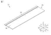
- the cutting blade 10 has a base material 20 .
- the base material 20 has a plate shape having a main surface MF.
- the "principal surface” is the surface with the largest area among the surfaces of the plate-shaped member.
- the base material 20 has a rectangular shape when the base material 20 is viewed in a direction perpendicular to the main surface MF.
- the axis along the long side of the four sides of the square substrate 20 is the first Let X be the axis. Further, when the substrate 20 is viewed in a direction orthogonal to the main surface MF, the axis along the short side of the four sides of the square substrate 20 is defined as a second axis Y. A third axis Z is defined as an axis extending in a direction orthogonal to the main surface MF.
- One of the directions along the first axis X is defined as a first positive direction X1, and the direction opposite to the first positive direction X1 among the directions along the first axis X is defined as a first negative direction X2.
- One of the directions along the second axis Y is defined as a second positive direction Y1, and the direction opposite to the second positive direction Y1 among the directions along the second axis Y is defined as a second negative direction Y2.
- One of the directions along the third axis Z is defined as a third positive direction Z1, and the direction opposite to the third positive direction Z1 among the directions along the third axis Z is defined as a third negative direction Z2.
- the end in the second positive direction Y1 is a cutting edge 23.
- the cutting edge 23 extends linearly along the outer edge of the base material 20 .
- the base material 20 has a cutting edge 23 over the entire end of the base material 20 in the second positive direction Y1.
- the cutting edge 23 is parallel to the first axis X.
- the edge of the base material 20 in the second negative direction Y2 forms a ridge 24 .
- the base material 20 has a ridge 24 across the edge opposite to the cutting edge 23 .
- the ridge 24 is parallel to the first axis as is the cutting edge 23 .
- the base material 20 has a peak side portion 21 and a blade side portion 22 .
- the ridge-side portion 21 is the portion of the substrate 20 that includes the ridge 24 .
- the crest side portion 21 has a rectangular shape elongated in the direction along the first axis X when the substrate 20 is viewed in the direction along the third axis Z. As shown in FIG.
- the dimension of the peak side portion 21 in the direction along the third axis Z, that is, the thickness of the peak side portion 21 is the same throughout the direction along the first axis X and the direction along the second axis Y. .
- the blade-side portion 22 is a portion of the substrate 20 that includes the cutting edge 23 .
- the dimension along the first axis X of the blade side portion 22 is the same as the dimension along the first axis X of the peak side portion 21 .
- the surface of the blade-side portion 22 facing the third positive direction Z1 is defined as a first substrate surface 22A. 22 A of 1st base-material surfaces incline so that it may be located in the 3rd negative direction Z2 side, so that it goes to the 2nd positive direction Y1.
- a surface of the blade-side portion 22 facing the third negative direction Z2 is defined as a second substrate surface 22B.
- the second base material surface 22B is inclined toward the third positive direction Z1 toward the second positive direction Y1.
- the dimension of the blade side portion 22 in the direction along the third axis Z decreases in the second positive direction Y1. That is, the blade-side portion 22 is a portion of the base material 20 that includes the blade edge 23 and has a thickness that decreases toward the blade edge 23 .
- the dimension of the substrate 20 in the direction along the first axis X is, for example, 100 mm or more and 300 mm or less.
- the dimension of the substrate 20 in the direction along the second axis Y is, for example, 20 mm or more and 30 mm or less.
- the dimension of the crest side portion 21 in the direction along the third axis Z is, for example, 0.05 mm or more and 0.5 mm or less.
- the material of the base material 20 is cemented carbide.
- Cemented carbide is sintered hard metal carbide powder.
- cemented carbide is obtained by sintering a mixture of tungsten carbide and cobalt as a binder.
- the cutting blade 10 is provided with a coating 30.
- the coating 30 covers the entire surface of the blade side portion 22 of the surface of the base material 20 . Therefore, the film 30 covers the cutting edge 23 of the substrate 20 . Moreover, the film 30 covers a portion of the surface of the peak side portion 21 including the end in the second positive direction Y1. The dimension of the film 30 in the direction along the second axis Y is substantially constant over the entire area in the direction along the first axis X. As shown in FIG.
- the material of coating 30 contains diamond. Therefore, the material of the coating 30 is harder than the cemented carbide that is the material of the base material 20 .
- the film 30 has a film body 31 and a plurality of projections 32.
- the membrane body 31 extends along the surface of the substrate 20 .
- the membrane body 31 is a range specified as follows. First, the necessary measurement range is specified.
- the measurement range is the range of a portion of the coating 30 excluding part of the edge of the coating 30 in a cross section passing through the center of the cutting edge 23 in the direction along the first axis X and perpendicular to the first axis X.
- the central range is set as the measurement range.
- the thinnest portion of the coating 30 is specified in the measurement range.
- the thinnest point is, for example, the dimension of the coating 30 perpendicular to the surface of the substrate 20 in the measurement range of the cross section passing through the center of the cutting edge 23 in the direction along the first axis X and perpendicular to the first axis X. is the point where is the smallest.
- a specific point that is 0.5 ⁇ m outside in the direction orthogonal to the surface of the base material 20 from the thinnest point is specified.
- a virtual line passing through the specific point and parallel to the surface of the substrate 20 is drawn.
- the area of the film 30 surrounded by the imaginary line and the surface of the substrate 20 is the main body 31 of the film.
- the surface roughness Rz of the film main body 31 defined as above is 0.5 ⁇ m or less. That is, the film main body 31 extends along the surface of the base material 20, and the film thickness of the portion of the film main body 31 that exists on the surface of the base material 20 is substantially constant. On the other hand, the film main body 31 may have fine unevenness that satisfies the condition that the surface roughness Rz is 0.5 ⁇ m or less. 3 and 4, the film thickness T2 of the film main body 31 existing on the first base material surface 22A and the second base material surface 22B of the base material 20 is illustrated as being uniform.
- the membrane body 31 covers the cutting edge 23 .
- a film thickness T1 at a portion of the film body 31 covering the cutting edge 23 is larger than a film thickness T2 at a portion of the film body 31 covering the blade side portion 22 excluding the cutting edge 23 .
- the film thickness T2 is the thickness of a portion of the blade side portion 22 that covers the first substrate surface 22A and the second substrate surface 22B. That is, the film thickness of the film main body 31 is the thickest at the portion covering the cutting edge 23 .
- the film thickness T1 is two to seven times the film thickness T2. It is assumed that a virtual tangent line is drawn with respect to a specific point on the surface of the base material 20 in a cross section orthogonal to the first axis X. FIG.
- the dimension of the film body 31 in the direction orthogonal to the imaginary tangent line is the thickness of the film body 31 at the portion covering the specific point.
- the film thickness T1 of the film body 31 at the portion covering the cutting edge 23 is the distance from the cutting edge 23 to the farthest portion of the outer surface of the film body 31 on the second positive direction Y1 side.
- the film thickness T1 is the distance from the cutting edge 23 to the tip 31E of the film main body 31 .
- the angle formed by the outer surfaces of the membrane body 31 sandwiching the tip 31E of the membrane body 31 is the angle on the side where the base material 20 exists. increases stepwise toward the tip 31E of the membrane main body 31.
- the outer surface of the membrane body 31 has a first inclined surface 31A, a second inclined surface 31B, a first tip surface 31C, and a second tip surface 31D.
- the first inclined surface 31A is the outer surface of the portion of the film body 31 that covers the first substrate surface 22A.
- the end of the first inclined surface 31 ⁇ /b>A in the second positive direction Y ⁇ b>1 is located on the second positive direction Y ⁇ b>1 side of the cutting edge 23 of the substrate 20 .
- the second inclined surface 31B is the outer surface of the portion of the film body 31 that covers the second substrate surface 22B.
- the end of the second inclined surface 31B in the second positive direction Y1 is positioned closer to the second positive direction Y1 than the cutting edge 23 of the substrate 20 .
- the first tip surface 31C is the outer surface of the portion of the membrane body 31 that covers the cutting edge 23 .
- the first tip surface 31C is a portion of the film body 31 between the tip 31E covering the cutting edge 23 and the first inclined surface 31A.
- the second tip surface 31D is the outer surface of the portion of the membrane body 31 that covers the cutting edge 23 .
- the second tip surface 31D is a portion of the film body 31 between the tip 31E covering the cutting edge 23 and the second inclined surface 31B.
- the first angle ⁇ 1 on the base material 20 side is smaller than 90 degrees.
- the second angle ⁇ 2 on the base material 20 side is smaller than 90 degrees.
- the second angle ⁇ 2 is larger than the first angle ⁇ 1.
- the protrusions 32 protrude from the outer surface of the membrane body 31 . That is, the projections 32 are portions of the coating 30 where the surface roughness Rz of the coating 30 exceeds 0.5 ⁇ m.
- the projection 32 has a hemispherical shape. Therefore, in a cross section orthogonal to the first axis X, the outer surface of the protrusion 32 is curved. In particular, in the cross section, the outer surface of the protrusion 32 is arcuate.
- a contact angle ⁇ 3 of the protrusion 32 with respect to the outer surface of the membrane main body 31 is an acute angle.
- the contact angle ⁇ 3 is the angle formed by the tangent line L3 at the contact point between the outer surface of the membrane main body 31 and the outer surface of the protrusion 32 on the side where the protrusion 32 exists.
- the tangent line L3 is a straight line passing through the contact point in a cross section perpendicular to the first axis X and perpendicular to a line segment connecting the contact point and the center of a virtual circle including the outer surface of the arcuate projection 32. is.
- some of the plurality of protrusions 32 are present on the first inclined surface 31A and the second inclined surface 31B of the outer surface of the membrane body 31 .
- Some of the plurality of protrusions 32 are positioned within a range from the cutting edge 23 to the tip 31E of the film main body 31 in the direction along the second axis Y. As shown in FIG. In particular, it is located within a range on the second positive direction Y1 side of the cutting edge 23 between the first inclined surface 31A and the second inclined surface 31B.
- some of the protrusions 32 are located on the side of the outer surface of the membrane body 31 where the tip 31E of the membrane body 31 exists with respect to the boundary line passing through the cutting edge 23 and parallel to the third axis Z.
- the plurality of protrusions 32 are distributed over the entire outer surface of the membrane body 31 . Therefore, as shown in FIG. 4, some of the plurality of protrusions 32 are arranged along the first axis X at intervals. That is, as shown in FIG. 3, a plurality of protrusions 32 are arranged along the cutting edge 23 at intervals.
- the number of projections 32 is 3 or more and 100 or less per square millimeter on the outer surface of the membrane body 31 .
- the number of protrusions 32 per square millimeter on the outer surface of the membrane body 31 is measured, for example, as follows. First, five areas per square millimeter on the outer surface of the membrane body 31 are randomly observed with a microscope.
- the number of protrusions 32 in each range is calculated. Then, the average value of the number of protrusions 32 in the range of five points is taken as the number of protrusions 32 per square millimeter on the outer surface of the membrane main body 31 .
- the protrusion amount of the projection 32 is 0.5% or more and 10% or less with respect to the substrate thickness TB, which is the maximum thickness of the blade side portion 22 .
- the base material thickness TB is equal to the thickness of the crest side portion 21 .
- the base material thickness TB is the dimension in the direction along the third axis Z of the contact portion between the crest side portion 21 and the blade side portion 22 .
- the protrusion amount of the protrusion 32 is the distance from the farthest point of the protrusion 32 from the surface of the substrate 20 in the direction perpendicular to the surface to the surface in the cross section perpendicular to the first axis X.
- the proportion of the protrusions 32 whose protrusion amount is 0.5% or more and 7% or less with respect to the substrate thickness TB is 90% or more.
- the protrusion amount of the protrusions 32 was measured for an example having a substrate thickness TB of 0.1 mm. All projection amounts of the protrusions 32 existing in a range of 0.3 mm along the outer surface of the membrane body 31 and 70 mm along the first axis X from the tip 31E of the membrane body 31 were measured. As a result, the protrusion amount of all protrusions 32 was 7 ⁇ m or less. That is, the protrusion amount of all protrusions 32 was 0.5% or more and 7% or less with respect to the substrate thickness TB.
- the method for manufacturing the cutting blade 10 includes a base material preparation step and a film forming step.
- the base material preparation process is performed.
- a plate-shaped member having a main surface MF is prepared.
- a part of the outer edge of the plate-like member when viewed in a direction orthogonal to the main surface MF is machined to form the base material 20 having the blade side portion 22 .
- the film forming process is performed.
- diamond coating is applied to a portion of the surface of the substrate 20 prepared in the substrate preparing step, which includes at least the surface of the blade side portion 22 .
- Diamond coating is performed by chemical vapor deposition, a so-called CVD (chemical vapor deposition) method.
- pretreatment of the base material 20 is performed.
- cobalt as a binder is removed from the surface of the base material 20 with a chemical solution or the like.
- the tungsten carbide particles are exposed on the surface of the substrate 20 .
- the surface of the pretreated base material 20 is seeded with diamond particles.
- the substrate 20 is immersed in a solvent in which diamond nanoparticles and diamond particles larger than the nanoparticles are dispersed. This causes the diamond particles to adhere to the tungsten carbide on the surface of the substrate 20 .
- the film forming apparatus 50 has a chamber 60 into which reaction gas is introduced.
- Chamber 60 has a reaction space 61 for chemical vapor deposition.
- the chamber 60 also has an inlet 62 for introducing the reaction gas into the reaction space 61 .
- the chamber 60 also has an exhaust port 63 for exhausting reacted gas from the reaction space 61 .
- the film forming apparatus 50 includes a heat source 80 that heats the substrate 20 inside the chamber 60 .
- Heat source 80 is a filament.
- the substrate 20 is held within the chamber 60 so that the heat source 80 is positioned on the cutting edge 23 side of the substrate 20 .
- a tip 31E, a first tip face 31C, and a second tip face 31D are formed at a portion of the film 30 that covers the cutting edge 23.
- the portion of the film 30 that covers the cutting edge 23 is processed by ion etching.
- the ion beam output and the like are controlled.
- the corner on the side where the substrate 20 exists is the tip of the membrane body 31. It forms so that it may become large gradually toward 31E.
- the coating 30 is formed on the substrate 20, and the cutting blade 10 is manufactured.
- the cutting blade 10 is reciprocated in the direction along the second Y axis. Then, the object to be cut is cut by bringing the blade side portion 22 into contact with the object to be cut.
- the film 30 covering the surface of the blade side portion 22 has protrusions 32 in addition to the film main body 31 . Therefore, the projection 32 comes into contact with the object to be cut.
- the protrusions 32 come into contact with each other, a gap is created between the outer surface of the membrane body 31 near the protrusions 32 and the object to be cut.
- the cutting blade 10 cuts the object to be cut, part of the object to be cut adheres to the surface of the projections 32 in the surface of the film 30 . On the other hand, the object to be cut does not adhere to the film main body 31 . That is, when the cutting blade 10 separates from the object to be cut, the protrusion 32 pushes the object to be cut away.
- the film thickness T1 of the portion of the film body 31 that covers the cutting edge 23 is greater than the film thickness T2 of the portion of the film body 31 that covers the blade-side portion 22 excluding the cutting edge 23 . ing. Therefore, the vicinity of the tip 31E of the film body 31 covering the cutting edge 23 tends to be sharp.
- the film thickness T1 is at least twice as large as the film thickness T2. Therefore, the strength of the cutting blade 10 in the vicinity of the cutting edge 23 of the substrate 20 can be considerably improved. Moreover, the film thickness T1 is seven times or less the film thickness T2. Therefore, the outer surface of the coating 30 covering the blade side portion 22 is not excessively sharp. Therefore, even if the tip 31E of the cutting blade 10 collides with the object to be cut, chipping or cracking can be further suppressed.
- the angle on the side where the base material 20 exists increases stepwise toward the tip 31E of the membrane main body 31.
- FIG. By changing the angle between the outer surfaces of the membrane body 31, when cutting the object by reciprocating the cutting blade 10 in the direction along the second axis Y, in the vicinity of the tip 31E of the membrane body 31, It becomes easy to create a portion that does not come into contact with the object to be cut. Therefore, the vicinity of the tip 31E of the film main body 31 can be prevented from coming into close contact with the object to be cut.
- some of the plurality of protrusions 32 are located within the range from the cutting edge 23 to the tip 31E of the membrane main body 31 .
- the protrusion 32 is also positioned near the cutting edge 23 . Therefore, even when cutting a correspondingly thin object with the cutting blade 10, the protrusions 32 are more likely to come into contact with the object to be cut. Therefore, the cutting blade 10 can more reliably avoid sticking the object to be cut.
- some of the plurality of protrusions 32 are arranged along the cutting edge 23 at intervals.
- the plurality of protrusions 32 are likely to come into contact with the object. In this case, it is easy to obtain a large space between the film main body 31 and the object to be cut between the plurality of projections 32 .
- the outer surface of the protrusion 32 is curved. Therefore, even if the protrusions 32 come into contact with the object to be cut, chipping or cracking of the protrusions 32 can be further suppressed. In addition, since the protrusions 32 come into contact with the object to be cut, the object to be cut is less likely to be damaged excessively.
- the contact angle ⁇ 3 of the protrusion 32 with respect to the outer surface of the membrane body 31 is an acute angle. Therefore, even if the protrusions 32 come into contact with the object to be cut, the protrusions 32 can be further prevented from being chipped or cracked. In addition, since the protrusions 32 come into contact with the object to be cut, the object to be cut is less likely to be damaged excessively.
- the protrusion amount of the protrusion 32 is 0.5% or more and 10% or less with respect to the substrate thickness TB, which is the maximum thickness of the blade side portion 22 . Since the protrusion amount of the protrusions 32 is 0.5% or more with respect to the base material thickness TB, the effect of making it easier for the workpiece to be cut to separate from the cutting blade 10 can be fully exhibited. In addition, since the protrusion amount of the protrusions 32 is 10% or less of the base material thickness TB, the protrusions 32 can be prevented from excessively scratching the surface of the object to be cut.
- the base material thickness TB that is, the dimension of the peak side portion 21 in the direction along the third axis Z is, for example, 0.05 mm or more and 0.5 mm or less. That is, the dimension of the substrate 20 in the direction along the third axis Z is considerably small. Therefore, if the protrusion 32 protrudes excessively, the substrate 20 may be distorted when it comes into contact with the object to be cut. According to the above-described embodiment, the amount of projection of the protrusion 32 is relatively small, so that such distortion of the base material 20 can be prevented.
- the proportion of the protrusions 32 whose protrusion amount is 0.5% or more and 7% or less with respect to the substrate thickness TB is 90% or more. It's becoming That is, most of the plurality of protrusions 32 have a protrusion amount of 0.5% or more and 7% or less with respect to the substrate thickness TB. Therefore, it is possible to prevent the load from being unevenly applied to some of the protrusions 32 due to excessive variations in the amount of protrusion of the protrusions 32 .
- the number of protrusions 32 is 3 or more and 100 or less per square millimeter on the outer surface of the membrane body 31 .
- the plurality of projections 32 and the object to be cut are in contact with each other, so that most of the film main body 31 tends to create a space between the object and the object to be cut within a range of 1 square millimeter.
- the number of projections 32 is 100 or less in the range of 1 square millimeter. Therefore, an excessive number of protrusions 32 is less likely to cause excessive scratches on the object to be cut.
- the shape of the base material 20 is not limited to the example of the above embodiment.
- the shape of the base material 20 may be a square shape or a rectangular shape whose dimension in the direction along the second axis Y is longer than in the direction along the first axis X when viewed from the direction along the third axis Z.
- the shape of the base material 20 may be such that one or both of the cutting edge 23 and the ridge 24 extend in an arc shape or in a wavy shape when viewed from the direction along the third axis Z.
- the substrate 20 is not limited to a so-called double-edged blade, and may be a single-edged blade.
- the cutting edge 23 may be a so-called saw blade. In this case, the cutting edge 23 may extend in a curved shape along the outer edge of the substrate 20 .
- the material of the base material 20 is not limited to the example of the above embodiment.
- the material of the base material 20 may be a cemented carbide containing titanium carbide, titanium carbonitride, or the like.
- the material of the substrate 20 is not limited to cemented carbide, and may be steel or ceramics.
- the size of the base material 20 is not limited to the example of the above embodiment.
- the dimension of the substrate 20 along the first axis X may be smaller than 100 mm or larger than 250 mm.
- the dimension of the substrate 20 in the direction along the second axis Y may be smaller than 20 mm or larger than 30 mm.
- the dimension of the peak side portion 21 in the direction along the third axis Z may be smaller than 0.05 mm or larger than 0.5 mm.
- the range in which the cutting edge 23 exists in the base material 20 is not limited to the example of the above embodiment.
- the cutting edge 23 when viewed from the direction along the third axis Z, the cutting edge 23 may be positioned on the short side of the rectangle, or the cutting edge 23 may be positioned on a part of one side of the rectangle. .
- the range covered with the film 30 is not limited to the example of the above embodiment.
- the coating 30 only needs to cover at least the cutting edge 23 .
- coating 30 may cover the entire surface of substrate 20 .
- the film thickness T1 of the portion of the film body 31 covering the cutting edge 23 may be less than or equal to the film thickness T2 of the portion of the film body 31 covering the blade side portion 22 excluding the cutting edge 23 . If the film thickness T1 is larger, the coating 30 covering the blade side portion 22 becomes sharper, making it easier to cut the object.
- the corner on the side where the base material 20 exists is at the tip 31E of the membrane body 31. It may be continuously increasing toward it.
- the outer surface of the film body 31 covering the cutting edge 23 may be arcuate in a cross section orthogonal to the first axis X.
- the angle on the side where the base material 20 exists increases continuously toward the tip 31E of the membrane body 31. .
- the vicinity of the tip 31E of the film main body 31 does not become excessively sharp, so chipping or cracking of the vicinity of the tip 31E is less likely to occur.
- the first angle ⁇ 1 may be 90 degrees or more
- the second angle ⁇ 2 may be 90 degrees or more. It may be changed according to the shape of the blade side portion 22 and the object to be cut.
- the corner on the side where the base material 20 exists is at the tip 31E of the membrane body 31. It may have a constant size toward it. Even in this case, since the material of the film 30 contains diamond, chipping and cracking of the tip 31E of the film main body 31 can be accordingly prevented.
- the number of protrusions 32 may be 2 or less, or may be 101 or more per square millimeter on the outer surface of the membrane body 31 . It is sufficient that a sufficient space is obtained between the outer surface of the membrane body 31 and the object to be cut in the vicinity of the projection 32 .
- the proportion of the protrusions 32 having a protrusion amount of 0.5% or more and 7% or less with respect to the substrate thickness TB may be less than 90%.
- the protrusion amount of the protrusions 32 may be less than 0.5% or may exceed 10% with respect to the substrate thickness TB.
- the amount of protrusion of the protrusions 32 with respect to the substrate thickness TB may be changed according to the type of the object to be cut. For example, if there is an inclusion inside the coating 30, there may be a protrusion 32 with a large amount of protrusion.
- the shape of the protrusion 32 is not limited to the example of the above embodiment.
- the contact angle ⁇ 3 of the protrusion 32 with respect to the outer surface of the membrane body 31 may be a right angle or an obtuse angle.
- the outer surface of the protrusion 32 may be linear. That is, the protrusion 32 may be polygonal.
- the plurality of protrusions 32 may not be arranged along the cutting edge 23 with a space therebetween.
- the plurality of protrusions 32 may be arranged at intervals only in the direction orthogonal to the cutting edge 23 .
- a plurality of protrusions 32 may be arranged in a line while shifting their positions in both the direction orthogonal to the cutting edge 23 and the direction along the cutting edge 23 .
- the protrusion 32 does not have to exist within the range from the cutting edge 23 to the tip 31E of the membrane body 31 .
- the protrusions 32 may be present only in a range of the film main body 31 that covers the first substrate surface 22A and the second substrate surface 22B.
- the protrusion 32 may exist in the vicinity of the tip 31E of the protrusion 32 by omitting the ion etching of the portion of the coating 30 that covers the cutting edge 23 .
- the cutting blade 10 is not limited to one manufactured by the manufacturing method according to the above embodiment.
- the protrusions 32 may be formed by sputtering or the like after diamond coating.
Landscapes
- Chemical & Material Sciences (AREA)
- Engineering & Computer Science (AREA)
- Mechanical Engineering (AREA)
- Life Sciences & Earth Sciences (AREA)
- Forests & Forestry (AREA)
- Chemical Kinetics & Catalysis (AREA)
- Materials Engineering (AREA)
- General Chemical & Material Sciences (AREA)
- Metallurgy (AREA)
- Organic Chemistry (AREA)
- Inorganic Chemistry (AREA)
- Nonmetal Cutting Devices (AREA)
- Chemical Vapour Deposition (AREA)
- Polishing Bodies And Polishing Tools (AREA)
Priority Applications (2)
| Application Number | Priority Date | Filing Date | Title |
|---|---|---|---|
| JP2023566159A JP7477057B2 (ja) | 2021-12-06 | 2022-10-31 | カット刃 |
| CN202280008774.1A CN116783045A (zh) | 2021-12-06 | 2022-10-31 | 切割刀 |
Applications Claiming Priority (2)
| Application Number | Priority Date | Filing Date | Title |
|---|---|---|---|
| JP2021-198093 | 2021-12-06 | ||
| JP2021198093 | 2021-12-06 |
Publications (1)
| Publication Number | Publication Date |
|---|---|
| WO2023105988A1 true WO2023105988A1 (ja) | 2023-06-15 |
Family
ID=86730216
Family Applications (1)
| Application Number | Title | Priority Date | Filing Date |
|---|---|---|---|
| PCT/JP2022/040602 Ceased WO2023105988A1 (ja) | 2021-12-06 | 2022-10-31 | カット刃 |
Country Status (3)
| Country | Link |
|---|---|
| JP (1) | JP7477057B2 (https=) |
| CN (1) | CN116783045A (https=) |
| WO (1) | WO2023105988A1 (https=) |
Cited By (1)
| Publication number | Priority date | Publication date | Assignee | Title |
|---|---|---|---|---|
| WO2025063119A1 (ja) * | 2023-09-20 | 2025-03-27 | 株式会社村田製作所 | カット刃及びカット刃の製造方法 |
Citations (4)
| Publication number | Priority date | Publication date | Assignee | Title |
|---|---|---|---|---|
| JPS62173193A (ja) * | 1986-01-24 | 1987-07-30 | 松下電工株式会社 | 刃物 |
| JP3054641B2 (ja) * | 1989-12-19 | 2000-06-19 | 旭ダイヤモンド工業株式会社 | 切断刃 |
| JP3134378B2 (ja) * | 1991-08-15 | 2001-02-13 | 住友電気工業株式会社 | ダイヤモンド被覆硬質材料 |
| JP2016210190A (ja) * | 2015-05-13 | 2016-12-15 | 東京シリコーン株式会社 | コーティング構造体 |
Family Cites Families (8)
| Publication number | Priority date | Publication date | Assignee | Title |
|---|---|---|---|---|
| JPH08289984A (ja) * | 1995-04-21 | 1996-11-05 | Sekisui Chem Co Ltd | 刃物及びその製造方法 |
| JP4741056B2 (ja) * | 2000-06-05 | 2011-08-03 | 株式会社貝印刃物開発センター | 刃部材及びその刃先の製造方法 |
| CN201009252Y (zh) * | 2007-02-15 | 2008-01-23 | 李积回 | 一种防粘刀 |
| JP5016961B2 (ja) * | 2007-03-30 | 2012-09-05 | 株式会社神戸製鋼所 | 刃部材 |
| KR100954726B1 (ko) * | 2008-04-25 | 2010-04-23 | (주)월드세라믹 | 비점착식 코팅층을 갖는 조리용 칼 및 코팅층 형성방법 |
| JP5297265B2 (ja) * | 2009-05-19 | 2013-09-25 | 住友電気工業株式会社 | 光ファイバ切断用カッター及び光ファイバの切断方法 |
| CN203003911U (zh) * | 2012-11-27 | 2013-06-19 | 林宸羽 | 一种带圆凸面防粘附装置菜刀 |
| KR102030057B1 (ko) * | 2019-08-13 | 2019-10-08 | 이준범 | 칼날을 오래 사용하고 음식물이 달라붙지 않는 칼 |
-
2022
- 2022-10-31 CN CN202280008774.1A patent/CN116783045A/zh active Pending
- 2022-10-31 WO PCT/JP2022/040602 patent/WO2023105988A1/ja not_active Ceased
- 2022-10-31 JP JP2023566159A patent/JP7477057B2/ja active Active
Patent Citations (4)
| Publication number | Priority date | Publication date | Assignee | Title |
|---|---|---|---|---|
| JPS62173193A (ja) * | 1986-01-24 | 1987-07-30 | 松下電工株式会社 | 刃物 |
| JP3054641B2 (ja) * | 1989-12-19 | 2000-06-19 | 旭ダイヤモンド工業株式会社 | 切断刃 |
| JP3134378B2 (ja) * | 1991-08-15 | 2001-02-13 | 住友電気工業株式会社 | ダイヤモンド被覆硬質材料 |
| JP2016210190A (ja) * | 2015-05-13 | 2016-12-15 | 東京シリコーン株式会社 | コーティング構造体 |
Cited By (1)
| Publication number | Priority date | Publication date | Assignee | Title |
|---|---|---|---|---|
| WO2025063119A1 (ja) * | 2023-09-20 | 2025-03-27 | 株式会社村田製作所 | カット刃及びカット刃の製造方法 |
Also Published As
| Publication number | Publication date |
|---|---|
| CN116783045A (zh) | 2023-09-19 |
| JPWO2023105988A1 (https=) | 2023-06-15 |
| JP7477057B2 (ja) | 2024-05-01 |
Similar Documents
| Publication | Publication Date | Title |
|---|---|---|
| JP5260924B2 (ja) | 切削インサート及びそれを用いた切削工具並びに切削方法 | |
| JP6194437B2 (ja) | 刃物 | |
| KR101348062B1 (ko) | 스크라이빙 휠 | |
| KR102362495B1 (ko) | 절단 공구 및 그 제조 방법 | |
| CN110997203A (zh) | 切削工具及其制造方法 | |
| CA2922827A1 (en) | Coated cutting tool | |
| WO2023105988A1 (ja) | カット刃 | |
| CN104174884B (zh) | 刀具 | |
| EP3363572A1 (en) | Blade | |
| US20040226176A1 (en) | Razor blades having a non-linear cutting edge and a method for manufacture thereof | |
| WO2020050263A1 (ja) | 被覆工具及び切削工具 | |
| JP2023022633A (ja) | カット刃の製造方法、及びカット刃 | |
| CN113909572B (zh) | 被覆切削工具 | |
| JPWO2018180911A1 (ja) | 切削インサート及び切削工具 | |
| EP0206494A1 (en) | Improved cutting edges | |
| JP7254225B2 (ja) | スリッターナイフおよびスリッター | |
| CN121398947A (zh) | 切割刀和切割刀的制造方法 | |
| JP2022138599A (ja) | カット刃、及びカット刃の製造方法 | |
| KR102780218B1 (ko) | 피복공구 및 그것을 구비한 절삭공구 | |
| CN103934484B (zh) | 刀具工具 | |
| JP2011173225A (ja) | ダイカッターおよびその製造方法 | |
| JP5053561B2 (ja) | 切削工具およびその製造方法 | |
| JP7839472B2 (ja) | 被覆切削工具 | |
| JP7839473B2 (ja) | 被覆切削工具 | |
| US20250381696A1 (en) | Razor blade |
Legal Events
| Date | Code | Title | Description |
|---|---|---|---|
| WWE | Wipo information: entry into national phase |
Ref document number: 202280008774.1 Country of ref document: CN |
|
| WWE | Wipo information: entry into national phase |
Ref document number: 2023566159 Country of ref document: JP |
|
| 121 | Ep: the epo has been informed by wipo that ep was designated in this application |
Ref document number: 22903920 Country of ref document: EP Kind code of ref document: A1 |
|
| NENP | Non-entry into the national phase |
Ref country code: DE |
|
| 122 | Ep: pct application non-entry in european phase |
Ref document number: 22903920 Country of ref document: EP Kind code of ref document: A1 |