WO2023100886A1 - 信号生成装置およびエレベータ - Google Patents
信号生成装置およびエレベータ Download PDFInfo
- Publication number
- WO2023100886A1 WO2023100886A1 PCT/JP2022/044003 JP2022044003W WO2023100886A1 WO 2023100886 A1 WO2023100886 A1 WO 2023100886A1 JP 2022044003 W JP2022044003 W JP 2022044003W WO 2023100886 A1 WO2023100886 A1 WO 2023100886A1
- Authority
- WO
- WIPO (PCT)
- Prior art keywords
- signal
- phase signal
- angle
- processing device
- output
- Prior art date
- Legal status (The legal status is an assumption and is not a legal conclusion. Google has not performed a legal analysis and makes no representation as to the accuracy of the status listed.)
- Ceased
Links
Images


Classifications
-
- G—PHYSICS
- G01—MEASURING; TESTING
- G01B—MEASURING LENGTH, THICKNESS OR SIMILAR LINEAR DIMENSIONS; MEASURING ANGLES; MEASURING AREAS; MEASURING IRREGULARITIES OF SURFACES OR CONTOURS
- G01B7/00—Measuring arrangements characterised by the use of electric or magnetic techniques
- G01B7/30—Measuring arrangements characterised by the use of electric or magnetic techniques for measuring angles or tapers; for testing the alignment of axes
-
- B—PERFORMING OPERATIONS; TRANSPORTING
- B66—HOISTING; LIFTING; HAULING
- B66B—ELEVATORS; ESCALATORS OR MOVING WALKWAYS
- B66B1/00—Control systems of elevators in general
- B66B1/34—Details, e.g. call counting devices, data transmission from car to control system, devices giving information to the control system
- B66B1/3492—Position or motion detectors or driving means for the detector
-
- G—PHYSICS
- G01—MEASURING; TESTING
- G01D—MEASURING NOT SPECIALLY ADAPTED FOR A SPECIFIC VARIABLE; ARRANGEMENTS FOR MEASURING TWO OR MORE VARIABLES NOT COVERED IN A SINGLE OTHER SUBCLASS; TARIFF METERING APPARATUS; MEASURING OR TESTING NOT OTHERWISE PROVIDED FOR
- G01D3/00—Indicating or recording apparatus with provision for the special purposes referred to in the subgroups
- G01D3/08—Indicating or recording apparatus with provision for the special purposes referred to in the subgroups with provision for safeguarding the apparatus, e.g. against abnormal operation, against breakdown
-
- G—PHYSICS
- G01—MEASURING; TESTING
- G01D—MEASURING NOT SPECIALLY ADAPTED FOR A SPECIFIC VARIABLE; ARRANGEMENTS FOR MEASURING TWO OR MORE VARIABLES NOT COVERED IN A SINGLE OTHER SUBCLASS; TARIFF METERING APPARATUS; MEASURING OR TESTING NOT OTHERWISE PROVIDED FOR
- G01D5/00—Mechanical means for transferring the output of a sensing member; Means for converting the output of a sensing member to another variable where the form or nature of the sensing member does not constrain the means for converting; Transducers not specially adapted for a specific variable
- G01D5/12—Mechanical means for transferring the output of a sensing member; Means for converting the output of a sensing member to another variable where the form or nature of the sensing member does not constrain the means for converting; Transducers not specially adapted for a specific variable using electric or magnetic means
- G01D5/14—Mechanical means for transferring the output of a sensing member; Means for converting the output of a sensing member to another variable where the form or nature of the sensing member does not constrain the means for converting; Transducers not specially adapted for a specific variable using electric or magnetic means influencing the magnitude of a current or voltage
- G01D5/142—Mechanical means for transferring the output of a sensing member; Means for converting the output of a sensing member to another variable where the form or nature of the sensing member does not constrain the means for converting; Transducers not specially adapted for a specific variable using electric or magnetic means influencing the magnitude of a current or voltage using Hall-effect devices
- G01D5/145—Mechanical means for transferring the output of a sensing member; Means for converting the output of a sensing member to another variable where the form or nature of the sensing member does not constrain the means for converting; Transducers not specially adapted for a specific variable using electric or magnetic means influencing the magnitude of a current or voltage using Hall-effect devices influenced by the relative movement between the Hall device and magnetic fields
-
- G—PHYSICS
- G01—MEASURING; TESTING
- G01D—MEASURING NOT SPECIALLY ADAPTED FOR A SPECIFIC VARIABLE; ARRANGEMENTS FOR MEASURING TWO OR MORE VARIABLES NOT COVERED IN A SINGLE OTHER SUBCLASS; TARIFF METERING APPARATUS; MEASURING OR TESTING NOT OTHERWISE PROVIDED FOR
- G01D5/00—Mechanical means for transferring the output of a sensing member; Means for converting the output of a sensing member to another variable where the form or nature of the sensing member does not constrain the means for converting; Transducers not specially adapted for a specific variable
- G01D5/12—Mechanical means for transferring the output of a sensing member; Means for converting the output of a sensing member to another variable where the form or nature of the sensing member does not constrain the means for converting; Transducers not specially adapted for a specific variable using electric or magnetic means
- G01D5/244—Mechanical means for transferring the output of a sensing member; Means for converting the output of a sensing member to another variable where the form or nature of the sensing member does not constrain the means for converting; Transducers not specially adapted for a specific variable using electric or magnetic means influencing characteristics of pulses or pulse trains; generating pulses or pulse trains
- G01D5/245—Mechanical means for transferring the output of a sensing member; Means for converting the output of a sensing member to another variable where the form or nature of the sensing member does not constrain the means for converting; Transducers not specially adapted for a specific variable using electric or magnetic means influencing characteristics of pulses or pulse trains; generating pulses or pulse trains using a variable number of pulses in a train
- G01D5/2451—Incremental encoders
-
- G—PHYSICS
- G01—MEASURING; TESTING
- G01D—MEASURING NOT SPECIALLY ADAPTED FOR A SPECIFIC VARIABLE; ARRANGEMENTS FOR MEASURING TWO OR MORE VARIABLES NOT COVERED IN A SINGLE OTHER SUBCLASS; TARIFF METERING APPARATUS; MEASURING OR TESTING NOT OTHERWISE PROVIDED FOR
- G01D5/00—Mechanical means for transferring the output of a sensing member; Means for converting the output of a sensing member to another variable where the form or nature of the sensing member does not constrain the means for converting; Transducers not specially adapted for a specific variable
- G01D5/54—Mechanical means for transferring the output of a sensing member; Means for converting the output of a sensing member to another variable where the form or nature of the sensing member does not constrain the means for converting; Transducers not specially adapted for a specific variable using means specified in two or more of groups G01D5/02, G01D5/12, G01D5/26, G01D5/42, and G01D5/48
- G01D5/56—Mechanical means for transferring the output of a sensing member; Means for converting the output of a sensing member to another variable where the form or nature of the sensing member does not constrain the means for converting; Transducers not specially adapted for a specific variable using means specified in two or more of groups G01D5/02, G01D5/12, G01D5/26, G01D5/42, and G01D5/48 using electric or magnetic means
-
- G—PHYSICS
- G01—MEASURING; TESTING
- G01D—MEASURING NOT SPECIALLY ADAPTED FOR A SPECIFIC VARIABLE; ARRANGEMENTS FOR MEASURING TWO OR MORE VARIABLES NOT COVERED IN A SINGLE OTHER SUBCLASS; TARIFF METERING APPARATUS; MEASURING OR TESTING NOT OTHERWISE PROVIDED FOR
- G01D5/00—Mechanical means for transferring the output of a sensing member; Means for converting the output of a sensing member to another variable where the form or nature of the sensing member does not constrain the means for converting; Transducers not specially adapted for a specific variable
- G01D5/54—Mechanical means for transferring the output of a sensing member; Means for converting the output of a sensing member to another variable where the form or nature of the sensing member does not constrain the means for converting; Transducers not specially adapted for a specific variable using means specified in two or more of groups G01D5/02, G01D5/12, G01D5/26, G01D5/42, and G01D5/48
- G01D5/58—Mechanical means for transferring the output of a sensing member; Means for converting the output of a sensing member to another variable where the form or nature of the sensing member does not constrain the means for converting; Transducers not specially adapted for a specific variable using means specified in two or more of groups G01D5/02, G01D5/12, G01D5/26, G01D5/42, and G01D5/48 using optical means, i.e. using infrared, visible or ultraviolet light
-
- G—PHYSICS
- G01—MEASURING; TESTING
- G01D—MEASURING NOT SPECIALLY ADAPTED FOR A SPECIFIC VARIABLE; ARRANGEMENTS FOR MEASURING TWO OR MORE VARIABLES NOT COVERED IN A SINGLE OTHER SUBCLASS; TARIFF METERING APPARATUS; MEASURING OR TESTING NOT OTHERWISE PROVIDED FOR
- G01D5/00—Mechanical means for transferring the output of a sensing member; Means for converting the output of a sensing member to another variable where the form or nature of the sensing member does not constrain the means for converting; Transducers not specially adapted for a specific variable
- G01D5/12—Mechanical means for transferring the output of a sensing member; Means for converting the output of a sensing member to another variable where the form or nature of the sensing member does not constrain the means for converting; Transducers not specially adapted for a specific variable using electric or magnetic means
- G01D5/244—Mechanical means for transferring the output of a sensing member; Means for converting the output of a sensing member to another variable where the form or nature of the sensing member does not constrain the means for converting; Transducers not specially adapted for a specific variable using electric or magnetic means influencing characteristics of pulses or pulse trains; generating pulses or pulse trains
- G01D5/24471—Error correction
-
- G—PHYSICS
- G01—MEASURING; TESTING
- G01D—MEASURING NOT SPECIALLY ADAPTED FOR A SPECIFIC VARIABLE; ARRANGEMENTS FOR MEASURING TWO OR MORE VARIABLES NOT COVERED IN A SINGLE OTHER SUBCLASS; TARIFF METERING APPARATUS; MEASURING OR TESTING NOT OTHERWISE PROVIDED FOR
- G01D5/00—Mechanical means for transferring the output of a sensing member; Means for converting the output of a sensing member to another variable where the form or nature of the sensing member does not constrain the means for converting; Transducers not specially adapted for a specific variable
- G01D5/26—Mechanical means for transferring the output of a sensing member; Means for converting the output of a sensing member to another variable where the form or nature of the sensing member does not constrain the means for converting; Transducers not specially adapted for a specific variable characterised by optical transfer means, i.e. using infrared, visible, or ultraviolet light
- G01D5/32—Mechanical means for transferring the output of a sensing member; Means for converting the output of a sensing member to another variable where the form or nature of the sensing member does not constrain the means for converting; Transducers not specially adapted for a specific variable characterised by optical transfer means, i.e. using infrared, visible, or ultraviolet light with attenuation or whole or partial obturation of beams of light
- G01D5/34—Mechanical means for transferring the output of a sensing member; Means for converting the output of a sensing member to another variable where the form or nature of the sensing member does not constrain the means for converting; Transducers not specially adapted for a specific variable characterised by optical transfer means, i.e. using infrared, visible, or ultraviolet light with attenuation or whole or partial obturation of beams of light the beams of light being detected by photocells
- G01D5/347—Mechanical means for transferring the output of a sensing member; Means for converting the output of a sensing member to another variable where the form or nature of the sensing member does not constrain the means for converting; Transducers not specially adapted for a specific variable characterised by optical transfer means, i.e. using infrared, visible, or ultraviolet light with attenuation or whole or partial obturation of beams of light the beams of light being detected by photocells using displacement encoding scales
Definitions
- the present invention relates to signal generators and elevators. This application claims priority based on Japanese Patent Application No. 2021-194064 filed in Japan on November 30, 2021, the content of which is incorporated herein.
- an optical encoder that outputs an A-phase signal and a B-phase signal, which have a phase difference of 90 electrical degrees from each other, as analog signals that are substantially sine waves.
- a magnetic encoder using a magnetoresistive element and a magnetic recording medium is also known.
- Japanese Patent Laid-Open No. 2002-200002 discloses a method for suppressing amplitude fluctuations of the A-phase signal and the B-phase signal output from a magnetic encoder, based on the deviation between the maximum output voltage of these sinusoidal signals and a reference voltage.
- a technique for feedback-controlling the voltage applied to the element is disclosed.
- Patent Document 2 in order to improve the resolution of a magnetic encoder, a sine wave signal with less distortion is output from the magnetoresistive element by setting the distance between the magnetoresistive element and the magnetic recording medium to a predetermined value. , discloses a technique of converting the sine wave signal into a pulse waveform and then multiplying the pulse waveform by a multiplier circuit.
- Optical encoders are often expensive because they consist of dedicated optical components that require microfabrication technology.
- the resolution is determined by the number of times (the number of cycles) that waveforms of one electrical angle cycle appear in the A phase signal and B phase signal in one mechanical angle cycle. It is difficult to change the resolution without changing the hardware, as the number depends on the number of graduation tracks provided on the graduation disk.
- the sine wave signal may be distorted due to uneven magnetization of the magnetic recording medium, which may reduce the angle detection accuracy.
- the number of cycles of the A-phase signal and the B-phase signal depends on the magnetic recording medium, so it is difficult to change the resolution without changing the hardware.
- One aspect of the signal generation device of the present invention is to calculate angle information indicating the mechanical angle of the rotating shaft, and based on the calculation result of the angle information, the waveform of one cycle of the electrical angle is generated N times in one cycle of the mechanical angle ( N is an integer equal to or greater than 1) and a second signal having a phase difference of 90 electrical degrees with respect to the first signal.
- a car suspended by a rope, a hoist that raises the car by hoisting the rope, and angle information indicating the mechanical angle of the rotation axis of the hoist are calculated. and the signal generation device according to the aspect described above, which generates at least the first signal and the second signal based on the calculation result of the angle information.
- the processing device can be configured with an inexpensive general-purpose microcomputer, at least the first signal and the second signal can be generated with a simpler and lower-cost configuration than a conventional optical encoder. It is possible to provide a signal generation device that can In addition, in conventional optical encoders, since the number of cycles of the first signal and the second signal depends on the number of scale tracks provided on the scale disc, it is difficult to change the resolution without changing the hardware. However, in the present invention, the number of cycles N of the first signal and the second signal can be set by software, so that the resolution can be changed without changing the hardware. Furthermore, since the first signal and the second signal can be generated using a D/A converter that is generally installed in a general-purpose microcomputer that can be used as a processing device, the first signal and the second signal can be generated with less distortion. can generate a signal.
- FIG. 1 is a block diagram schematically showing the configuration of a signal generator according to one embodiment of the present invention.
- FIG. 2 is a timing chart showing temporal correspondences among the timing of interrupt signal generation, the timing of change in the number of interrupts, the timing of execution of interrupt processing, the operation timing of the A/D converter, and the timing of execution of angle calculation processing. Chart.
- FIG. 3 is a flowchart showing interrupt processing executed by the first arithmetic unit of the first processing unit (main MPU).
- FIG. 4 is a diagram for explaining absolute angle delay compensation.
- FIG. 5 is a diagram showing an example of an absolute angle function.
- FIG. 6 is a flowchart showing signal generation processing executed by the second arithmetic unit of the second processing unit (sub MPU).
- FIG. 1 is a block diagram schematically showing the configuration of a signal generator according to one embodiment of the present invention.
- FIG. 2 is a timing chart showing temporal correspondences among the timing of interrupt signal generation, the timing of change in the number of
- FIG. 7 is a diagram showing an example of the waveform of the fifth signal (R phase signal).
- FIG. 8 is a diagram showing an example of a differential signal output from the output circuit of the signal generation device.
- FIG. 9 is a diagram showing an example of waveforms of the A-phase signal, the B-phase signal, and the R-phase signal in the first embodiment.
- FIG. 10 is an enlarged view of the area indicated by numeral 200 in FIG.
- FIG. 11 is a block diagram schematically showing the configuration of the signal generation device according to the second embodiment of the present invention.
- FIG. 12 is a diagram showing an example of waveforms of the A-phase signal, the B-phase signal, and the output signal of the arithmetic circuit in the second embodiment.
- FIG. 13 is a diagram showing an example of waveforms of the A-phase signal, the B-phase signal, and the R-phase signal in the second embodiment.
- FIG. 14 is a diagram showing the appearance of an elevator that is an application example of the present invention.
- FIG. 1 is a block diagram schematically showing the configuration of a signal generator 1 according to one embodiment of the present invention.
- the signal generation device 1 in this embodiment includes a sensor section 10 , a processing device 20 , a filter circuit 50 and an output circuit 60 .
- the sensor unit 10 has three magnetic sensors 11, 12 and 13, for example.
- Each of the magnetic sensors 11, 12, and 13 is a Hall sensor that detects the magnetic flux intensity that changes according to the rotation angle of the rotating shaft and outputs an analog signal indicating the detection result of the magnetic flux intensity as a magnetic flux detection signal.
- the rotating shaft is, for example, the rotor shaft of a three-phase brushless DC motor.
- a three-phase brushless DC motor is equipped with a control board that supplies drive currents to the three-phase coils.
- the magnetic sensors 11, 12 and 13 are arranged on the control board so as to face the rotor magnets in the axial direction of the rotor shaft. Further, the magnetic sensors 11, 12 and 13 are arranged at regular intervals along the rotation direction of the rotor shaft when viewed from the axial direction of the rotor shaft. The regular intervals are, for example, 120 degree intervals.
- the magnetic sensor 11 outputs to the processing device 20 a magnetic flux detection signal Hu indicating the detection result of the magnetic flux intensity in the U phase.
- the magnetic sensor 12 outputs to the processing device 20 a magnetic flux detection signal Hv indicating the detection result of the magnetic flux intensity in the V phase.
- the magnetic sensor 13 outputs a magnetic flux detection signal Hw indicating the detection result of the magnetic flux intensity in the W phase to the processing device 20 .
- the three magnetic flux detection signals Hu, Hv and Hw have a phase difference of 120 electrical degrees from each other.
- the processing device 20 calculates angle information indicating the mechanical angle of the rotating shaft, and based on the calculation result of the angle information, the waveform of one cycle of the electrical angle appears N times (N is an integer equal to or greater than 1) in one cycle of the mechanical angle.
- a first signal VA and a second signal VB having a phase difference of 90 electrical degrees with respect to the first signal VA are generated.
- the first signal VA may be called “A phase signal” and the second signal VB may be called “B phase signal”.
- the A phase signal VA is a sine wave signal and the B phase signal VB is a cosine wave signal.
- the processing device 20 Based on the result of calculation of the angle information, the processing device 20 generates a third signal VC in which a waveform of one electrical angle cycle appears once in one mechanical angle cycle, and a third signal VC that is 90 degrees in electrical angle with respect to the third signal VC.
- a fourth signal VD having a phase difference is also generated.
- the third signal VC may be called the "C phase signal” and the fourth signal VD may be called the "D phase signal”.
- the C-phase signal VC is a sine wave signal and the D-phase signal VD is a cosine wave signal.
- the processing device 20 further generates a fifth signal VR indicating the reference position of one cycle of the mechanical angle based on the result of calculation of the angle information.
- the fifth signal VR may be called an "R phase signal”.
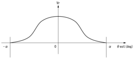
- the R-phase signal VR has a waveform that is symmetrical within a range of ⁇ degrees centered on the mechanical angle of 0 degrees, and whose peak appears at the mechanical angle of 0 degrees.
- a waveform represented by a sigmoid function, a rectangular wave, a triangular wave, a sine wave, or the like can be used as the waveform of the R-phase signal VR.
- the processor 20 outputs the A-phase signal VA, the B-phase signal VB, the C-phase signal VC, the D-phase signal VD, and the R-phase signal VR to the filter circuit 50 .
- the processing device 20 includes a first processing device 30 that calculates angle information, generates an A-phase signal VA and a B-phase signal VB based on the calculation result of the angle information, and an angle obtained from the first processing device 30 . and a second processing device 40 for generating a C-phase signal VC, a D-phase signal VD, and an R-phase signal VR based on the result of computing the information.
- the first processing device 30 and the second processing device 40 communicate the calculation result of the angle information.
- the first processing device 30 and the second processing device 40 are processor ICs such as MPUs (Micro Processing Units), for example. In the following description, the first processing unit 30 may be called “main MPU” and the second processing unit 40 may be called "sub MPU".
- the main MPU 30 calculates angle information indicating the mechanical angle of the rotating shaft based on the magnetic flux detection signals Hu, Hv, and Hw output from the sensor unit 10, and based on the calculation result of the angle information, the A-phase signal VA and B-phase signal Generates signal VB.
- the main MPU 30 transmits the calculation result of angle information to the sub MPU 40 .
- the main MPU 30 includes an A/D converter 31, a timer 32, a first computing unit 33, a first storage unit 34, a first D/A converter 35, a first communication I/F 36, Prepare.
- the magnetic flux detection signals Hu, Hv, and Hw output from the sensor section 10 are input to the A/D converter 31 of the main MPU 30 .
- the A/D converter 31 converts each of the magnetic flux detection signals Hu, Hv, and Hw into digital data by sampling them at a predetermined sampling frequency, and converts the digital data of the magnetic flux detection signals Hu, Hv, and Hw to a first calculation unit. 33.
- the timer 32 outputs an interrupt signal INT to the first computing section 33 at a predetermined cycle. Specifically, the timer 32 increments the timer count value in synchronization with a clock signal (not shown), and outputs an interrupt signal INT and resets the timer count value when the timer count value reaches a timer reset value TRES. . In this manner, the cycle of outputting the interrupt signal INT from the timer 32 is determined by the timer reset value TRES.
- the timer reset value TRES is set in the timer 32 by the first calculator 33 .
- the first computing unit 33 is a processor core that executes various processes according to programs pre-stored in the first storage unit 34 . Although details will be described later, when the interrupt signal INT is input from the timer 32, the first computing unit 33, based on the digital data of the magnetic flux detection signals Hu, Hv, and Hw input from the A/D converter 31, Interrupt processing is executed to calculate the angle estimated value ⁇ est as angle information.
- the first calculation unit 33 generates the A-phase digital signal DVA and the B-phase digital signal DVB based on the calculation result of the estimated angle value ⁇ est during execution of the interrupt process, and outputs them to the first D/A converter 35 . do. Further, the first calculation unit 33 transmits digital data indicating the calculation result of the estimated angle value ⁇ est to the sub MPU 40 via the first communication I/F 36 when executing the interrupt process.
- the first storage unit 34 includes a non-volatile memory that stores in advance programs and setting data necessary for causing the first calculation unit 33 to execute various processes, and a and volatile memory that is used as a temporary data storage destination.
- Non-volatile memory includes, for example, EEPROM (Electrically Erasable Programmable Read-Only Memory) and flash memory.
- Volatile memory is, for example, RAM (Random Access Memory).
- the first D/A converter 35 is, for example, a 2-channel D/A converter.
- the first D/A converter 35 converts the A-phase digital signal DVA output from the first calculation unit 33 into an analog signal to generate the A-phase signal VA.
- the first D/A converter 35 converts the B-phase digital signal DVB output from the first computing section 33 into an analog signal to generate the B-phase signal VB.
- the first D/A converter 35 outputs the A-phase signal VA and the B-phase signal VB to the filter circuit 50 .
- the first communication I/F 36 is a serial communication interface that communicates with the second communication I/F 41 of the sub MPU 40 according to, for example, the SPI (Serial Peripheral Interface) communication standard.
- 1st communication I/F36 transmits the digital data output from the 1st calculating part 33 to 2nd communication I/F41 of sub MPU40.
- the first communication I/F 36 receives digital data transmitted from the second communication I/F 41 of the sub-MPU 40 and outputs the received digital data to the first computing section 33 .
- the digital data transmitted from the first calculation unit 33 to the sub MPU 40 via the first communication I/F 36 includes digital data indicating the calculation result of the estimated angle value ⁇ est.
- the sub-MPU 40 generates the C-phase signal VC, the D-phase signal VD, and the R-phase signal VR based on the calculation result of the angle information transmitted from the main MPU 30, that is, the calculation result of the angle estimated value ⁇ est.
- the sub MPU 40 includes a second communication I/F 41 , a second computing section 42 , a second storage section 43 and a second D/A converter 44 .
- the second communication I/F 41 is a serial communication interface that communicates with the first communication I/F 36 of the main MPU 30 according to, for example, the SPI communication standard.
- the second communication I/F 41 transmits the digital data output from the second calculation section 42 to the first communication I/F 36 of the main MPU 30 .
- the second communication I/F 41 receives digital data transmitted from the first communication I/F 36 of the main MPU 30 and outputs the received digital data to the second computing section 42 .
- the second computing unit 42 is a processor core that executes various processes according to programs pre-stored in the second storage unit 43 .
- the second calculation unit 42 receives the calculation result of the estimated angle value ⁇ est from the main MPU 30 via the second communication I/F 41, the second calculation unit 42 calculates the C-phase digital signal DVC based on the received calculation result of the estimated angle value ⁇ est.
- D-phase digital signal DVD, and R-phase digital signal DVR are generated and output to the second D/A converter 44 .
- the second storage unit 43 includes a non-volatile memory that stores in advance programs and setting data necessary for causing the second calculation unit 42 to perform various processes, and a second storage unit 42 that performs various processes. and volatile memory that is used as a temporary data storage destination.
- Non-volatile memories are, for example, EEPROMs and flash memories.
- Volatile memory is, for example, RAM.
- the second D/A converter 44 is, for example, a 3-channel D/A converter.
- the second D/A converter 44 converts the C-phase digital signal DVC output from the second computing section 42 into an analog signal to generate the C-phase signal VC.
- the second D/A converter 44 converts the D-phase digital signal DVD output from the second computing section 42 into an analog signal to generate a D-phase signal VD.
- the second D/A converter 44 converts the R-phase digital signal DVR output from the second computing section 42 into an analog signal to generate the R-phase signal VR.
- the second D/A converter 44 outputs the C-phase signal VC, D-phase signal VD and R-phase signal VR to the filter circuit 50 .
- the filter circuit 50 includes a first low-pass filter 51, a second low-pass filter 52, a third low-pass filter 53, a fourth low-pass filter 54, and a fifth low-pass filter 55.
- the first low-pass filter 51, the second low-pass filter 52, the third low-pass filter 53, the fourth low-pass filter 54, and the fifth low-pass filter 55 are, for example, second order RC low-pass filters.
- the first low-pass filter 51 is provided on the transmission path of the A-phase signal VA output from the main MPU 30 of the processing device 20 .
- the first low-pass filter 51 passes, to the output circuit 60 , frequency components below a predetermined cutoff frequency among the frequency components contained in the A-phase signal VA output from the main MPU 30 .
- the signal output from the first low-pass filter 51 has a smoother sine waveform than the A-phase signal VA input to the first low-pass filter 51 .
- the signal output from the first low-pass filter 51 is different from the A-phase signal VA input to the first low-pass filter 51, but in this embodiment, for convenience of explanation,
- the output signal is also called "A phase signal VA".
- the second low-pass filter 52 is provided on the transmission path of the B-phase signal VB output from the main MPU 30 of the processing device 20 .
- the second low-pass filter 52 passes, to the output circuit 60 , frequency components below a predetermined cutoff frequency among the frequency components contained in the B-phase signal VB output from the main MPU 30 .
- the signal output from the second low-pass filter 52 has a smoother cosine waveform than the B-phase signal VB input to the second low-pass filter 52 .
- the signal output from the second low-pass filter 52 is different from the B-phase signal VB input to the second low-pass filter 52.
- the output signal is also called "B-phase signal VB".
- the third low-pass filter 53 is provided on the transmission path of the C-phase signal VC output from the sub MPU 40 of the processing device 20.
- the third low-pass filter 53 passes, to the output circuit 60 , frequency components below a predetermined cutoff frequency among the frequency components contained in the C-phase signal VC output from the sub MPU 40 .
- the signal output from the third low-pass filter 53 has a smoother sine waveform than the C-phase signal VC input to the third low-pass filter 53 .
- the signal output from the third low-pass filter 53 is different from the C-phase signal VC input to the third low-pass filter 53, but in this embodiment, for convenience of explanation,
- the output signal is also called "C-phase signal VC".
- a fourth low-pass filter 54 is provided in the transmission path of the D-phase signal VD output from the sub-MPU 40 of the processing device 20 .
- the fourth low-pass filter 54 passes frequency components below a predetermined cutoff frequency out of the frequency components contained in the D-phase signal VD output from the sub MPU 40 to the output circuit 60 .
- the signal output from the fourth low-pass filter 54 has a smoother cosine waveform than the D-phase signal VD input to the fourth low-pass filter 54 .
- the signal output from the fourth low-pass filter 54 is different from the D-phase signal VD input to the fourth low-pass filter 54, but in this embodiment, for convenience of explanation,
- the output signal is also called "D-phase signal VD".
- a fifth low-pass filter 55 is provided in the transmission path of the R-phase signal VR output from the sub-MPU 40 of the processing device 20 .
- the fifth low-pass filter 55 passes frequency components below a predetermined cutoff frequency out of the frequency components contained in the R-phase signal VR output from the sub MPU 40 to the output circuit 60 .
- the signal output from the fifth low-pass filter 55 has a smoother waveform than the R-phase signal VR input to the fifth low-pass filter 55 .
- the signal output from the fifth low-pass filter 55 is different from the R-phase signal VR input to the fifth low-pass filter 55.
- the output signal is also called "R phase signal VR".
- the output circuit 60 is a circuit that generates and outputs differential signals of the A-phase signal VA, B-phase signal VB, C-phase signal VC, D-phase signal VD, and R-phase signal VR output from the filter circuit 50. is.
- the output circuit 60 includes a first differential output circuit 61, a second differential output circuit 62, a third differential output circuit 63, a fourth differential output circuit 64, and a fifth differential output circuit 64. and an output circuit 65 .
- a first differential output circuit 61 generates a differential signal of the A-phase signal VA output from the first low-pass filter 51 .
- the differential signal output from the first differential output circuit 61 is a signal having the same phase as the A-phase signal VA input from the first low-pass filter 51 to the first differential output circuit 61. It includes a phase signal A+ and a negative A-phase signal A-, which is a signal opposite in phase to the positive A-phase signal A+.
- a second differential output circuit 62 generates a differential signal of the B-phase signal VB output from the second low-pass filter 52 .
- the differential signal output from the second differential output circuit 62 is a signal having the same phase as the B-phase signal VB input from the second low-pass filter 52 to the second differential output circuit 62. It includes a phase signal B+ and a negative side B phase signal B ⁇ that is a signal in opposite phase to the positive side B phase signal B+.
- a third differential output circuit 63 generates a differential signal of the C-phase signal VC output from the third low-pass filter 53 .
- the differential signal output from the third differential output circuit 63 is a signal having the same phase as the C-phase signal VC input from the third low-pass filter 53 to the third differential output circuit 63. It includes a phase signal C+ and a negative side C-phase signal C ⁇ that is a signal opposite in phase to the positive side C-phase signal C+.
- a fourth differential output circuit 64 generates a differential signal of the D-phase signal VD output from the fourth low-pass filter 54 .
- the differential signal output from the fourth differential output circuit 64 is a signal having the same phase as the D-phase signal VD input from the fourth low-pass filter 54 to the fourth differential output circuit 64. It includes a phase signal D+ and a negative side D-phase signal D- that is a signal opposite in phase to the positive side D-phase signal D+.
- a fifth differential output circuit 65 generates a differential signal of the R-phase signal VR output from the fifth low-pass filter 55 .
- the differential signal output from the fifth differential output circuit 65 is a signal having the same phase as the R-phase signal VR input from the fifth low-pass filter 55 to the fifth differential output circuit 65. It includes a phase signal R+ and a negative side R-phase signal R- that is a signal opposite in phase to the positive side R-phase signal R+.
- the first calculation unit 33 of the main MPU 30 and the second calculation unit 42 of the sub MPU 40 each execute predetermined initialization processing.
- the first calculation unit 33 reads the timer reset value TRES of the timer 32 from the first storage unit 34 and sets the read timer reset value TRES in the timer 32 as one of the initialization processes.
- the first calculation unit 33 resets the value of the number of interrupts count, which will be described later, to "0" as one of the initialization processes.
- FIG. 2 shows temporal correspondence relationships among the timing of generation of the interrupt signal INT, the timing of change in the number of interrupts count, the timing of execution of interrupt processing, the operation timing of the A/D converter 31, and the timing of execution of angle calculation processing.
- the interrupt signal INT is output from the timer 32 at a predetermined cycle T INT .
- the first arithmetic unit 33 performs interrupt processing each time an interrupt signal INT is generated. , a predetermined short-cycle process is performed after a predetermined long-cycle process is performed. On the other hand, if the number of interrupts count is not equal to the initial value "0", the short-cycle process is performed without performing the long-cycle process.
- the number of interrupts count is reset to the initial value "0" when it exceeds the maximum value "Cm".
- the period T period in which the number of interrupts count is reset is called a "control period”.
- the control period T period is represented by the following formula (1).
- the long period processing included in the interrupt processing is processing that is repeatedly executed at a period equal to the control period T period .
- the short-cycle processing included in the interrupt processing is processing that is repeatedly executed at a cycle equal to the generation cycle T INT of the interrupt signal INT.
- T period (Cm+1) ⁇ T INT ... (1)
- the sensor unit 10 When the rotary shaft rotates, the sensor unit 10 outputs magnetic flux detection signals Hu, Hv, and Hw having a phase difference of 120 electrical degrees from each other.
- the A/D converter 31 starts digital conversion of the magnetic flux detection signals Hu, Hv and Hw, and when the number of interrupts count is "2", for example.
- the digital conversion ends. In other words, digital data of the magnetic flux detection signals Hu, Hv, and Hw in one control cycle is obtained while the number of interrupts count changes from the initial value "0" to "2".
- the first calculation unit 33 acquires the digital data of the magnetic flux detection signals Hu, Hv, and Hw, the first calculation unit 33 executes angle calculation processing while interrupt processing is not executed.
- the first calculator 33 calculates the absolute angle ⁇ (mechanical angle) of the rotating shaft based on the digital data of the magnetic flux detection signals Hu, Hv, and Hw.
- an algorithm for calculating the absolute angle ⁇ for example, an algorithm described in Japanese Patent No. 6233532 can be used. Therefore, in this specification, the description of the calculation algorithm for the absolute angle ⁇ is omitted.
- the algorithm for calculating the absolute angle ⁇ is not limited to the algorithm described in Japanese Patent No. 6233532. Other calculation algorithms may be used as long as they can calculate the absolute angle of the rotation axis.
- the angle calculation process executed within one control cycle is terminated.
- the first calculation unit 33 substitutes the calculation result of the absolute angle ⁇ into the global variable gwTheta.
- the period at which the value of the global variable gwTheta indicating the absolute angle ⁇ is rewritten to a new value is equal to the control period T period .
- the control period T period is the period in which the absolute angle ⁇ of the rotating shaft is updated.
- FIG. 3 is a flowchart showing interrupt processing executed by the first calculation unit 33.
- the first calculation unit 33 executes the interrupt processing shown in FIG.
- the first calculation unit 33 first determines whether or not the number of interrupts count is equal to the initial value "0" (step S1). If “Yes” in step S1, that is, if the number of interrupts count is equal to the initial value "0”, the first calculation unit 33 proceeds to the process of step S2. On the other hand, if "No” in step S1, that is, if the number of interrupts count is not equal to the initial value "0", the first calculation unit 33 proceeds to the process of step S5.
- processing from step S2 to step S4 is long cycle processing.
- processing from step S5 to step S11 is short cycle processing. That is, when the number of interrupts count is equal to the initial value "0", the first calculation unit 33 executes the long cycle processing including the processing from step S2 to step S4, and then performs the processing from step S5 to step S11. Executes short-cycle processing including On the other hand, when the number of interrupts "count" is not equal to the initial value "0", the first calculation unit 33 executes the short period processing without executing the long period processing.
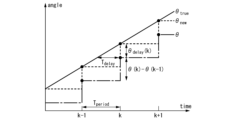
- the first computing unit 33 executes angle acquisition processing for acquiring the current value of the absolute angle ⁇ of the rotation axis as one of the long-cycle processing (step S2). Specifically, in step S2, the first calculator 33 acquires the value of the global variable gwTheta as the current value Theta of the absolute angle ⁇ . As shown in FIG. 2, the current value Theta of the absolute angle .theta. is the value of the absolute angle .theta. calculated in the control cycle immediately preceding the current control cycle.
- the first computing unit 33 performs an absolute A function calculation process for calculating an angle function is executed (steps S3 and S4).
- the previous value Theta_prev of the absolute angle ⁇ is the value of the absolute angle ⁇ calculated in the control cycle two cycles before the current control cycle.
- the first calculation unit 33 performs an intercept calculation process for calculating the intercept of the absolute angle function by performing delay compensation on the current value Theta of the absolute angle ⁇ .
- the current value Theta of the absolute angle ⁇ includes the following time lag components.
- the current value Theta of the absolute angle ⁇ is the value of the absolute angle ⁇ calculated in the control cycle immediately preceding the current control cycle. Therefore, the current value Theta of the absolute angle ⁇ has a time delay corresponding to one control cycle.
- the current value Theta of the absolute angle ⁇ has a time delay due to response delays of the magnetic sensors 11 , 12 and 13 .
- the current value Theta of the absolute angle ⁇ has a time delay due to the frequency characteristics of the low-pass filter.
- step S3 the first calculation unit 33 performs delay compensation on the current value Theta of the absolute angle ⁇ having the time delay component as described above.
- ⁇ is the absolute angle ⁇ calculated by the angle arithmetic processing
- ⁇ true is the true value of the absolute angle ⁇
- ⁇ new is the delay-compensated absolute angle ⁇ .
- Tdelay time delay in the absolute angle ⁇
- an angle error ⁇ delay occurs in the absolute angle ⁇ with respect to the true value ⁇ new.
- the delay-compensated absolute angle ⁇ new is represented by the following equation (2).
- ⁇ (k) is equal to the current value Theta of the absolute angle ⁇
- ⁇ (k ⁇ 1) is equal to the previous value Theta_prev of the absolute angle ⁇ .
- the second term on the right side is equal to the angle error ⁇ delay .
- step S3 the first calculator 33 calculates the delay-compensated absolute angle ⁇ new as the intercept of the absolute angle function based on the above equation (2).
- the first calculator 33 acquires the calculation result of the delay-compensated absolute angle ⁇ new as the intercept Theta_new_low.
- T delay included in the above equation (2) a calculated value obtained by performing a simulation considering the above-described time delay factor may be used, or it may be obtained by conducting an experiment. A measured value may be used.
- step S2 to step S4 described above is a long period processing that is repeatedly executed at a period equal to the control period T period .
- short cycle processing will be described.
- the first calculation unit 33 executes an estimated angle value calculation process for calculating an estimated value of the absolute angle ⁇ as the estimated angle value ⁇ est based on the absolute angle function calculated by the function calculation process. (step S5). Specifically, in step S5, the first calculation unit 33 assigns the value of ⁇ (count) calculated by substituting the value of the current number of interrupts count into the above equation (4) as the estimated angle value ⁇ est. get.
- the straight line L shows an example of the absolute angle function ⁇ (count) calculated when the number of interrupts count is "0" in any one control cycle.
- the slope of the straight line L is the slope Theta_extr of the absolute angle function ⁇ (count).
- the value of the point P0 on the straight line L is the estimated angle value ⁇ est calculated when the number of interrupts count is "0".
- the value of point P0 is equal to the intercept Theta_new_low of the absolute angle function ⁇ (count).
- the value of the point P2 on the straight line L is the estimated angle value ⁇ est calculated when the number of interrupts count is "2".
- the value of the point P3 on the straight line L is the estimated angle value ⁇ est calculated when the number of interrupts count is "3".
- the value of the point P5 on the straight line L is the estimated angle value ⁇ est calculated when the number of interrupts count is "5".
- the value of the point P7 on the straight line L is the estimated angle value ⁇ est calculated when the number of interrupts count is "7".
- the first calculation unit 33 calculates the estimated angle value ⁇ est corresponding to the value of the current number of interrupts count. 5) Calculate the instantaneous value Va of the A-phase signal VA based on the equation (step S6), and calculate the instantaneous value Vb of the B-phase signal VB based on the following equation (6) (step S7).
- K and N are constants. N is the number of times (the number of cycles) that waveforms of one electrical angle cycle appear in the A-phase signal VA and the B-phase signal VB in one mechanical angle cycle.
- the resolution is determined by the number of cycles N of the A-phase signal VA and the B-phase signal VB.
- N is 2048.
- Va K ⁇ sin (N ⁇ est) (5)
- Vb K ⁇ cos(N ⁇ est) (6)
- the first calculation unit 33 outputs digital data indicating the calculation result of the instantaneous value Va of the A-phase signal VA as the A-phase digital signal DVA to the first D/A converter 35, and also outputs the instantaneous value of the B-phase signal VB. Digital data indicating the calculation result of Vb is output to the first D/A converter 35 as a B-phase digital signal DVB.
- the first calculation unit 33 refers to the table data stored in advance in the first storage unit 34 to obtain the instantaneous value Va of the A-phase signal VA and the B-phase signal VB corresponding to the estimated angle value ⁇ est. An instantaneous value Vb may be acquired.
- the first calculation unit 33 transmits digital data indicating the calculation result of the estimated angle value ⁇ est to the sub MPU 40 via the first communication I/F 36 (step S8).
- the first calculation unit 33 executes an interrupt number update process for updating the number of interrupts count (step S9). Specifically, in step S9, the first calculation unit 33 increments the value of the number of interrupts count.
- the first calculation unit 33 determines whether or not the number of interrupts count is equal to a predetermined threshold value Cth (step S10).
- the first arithmetic unit 33 repeatedly executes the above-described interrupt processing at the generation cycle T INT of the interrupt signal INT, so that the phase A signal VA, which is an analog sine wave signal, and the analog signal VA, which is a cosine wave, are generated.
- a B-phase signal VB (that is, a B-phase signal VB having a 90-degree electrical angle phase difference with respect to the A-phase signal VA) is output from the first D/A converter 35 to the filter circuit 50 .
- N of the A-phase signal VA and the B-phase signal VB is 2048
- the A-phase signal VA and In the B-phase signal VB a waveform of one electrical angle cycle appears 2048 times.
- the first calculation unit 33 repeatedly executes the above-described interrupt processing at the generation cycle T INT of the interrupt signal INT , so that the angle estimated value ⁇ est is transmitted from the main MPU 30 to the sub MPU 40 .
- FIG. 6 is a flowchart showing signal generation processing executed by the second calculation unit 42 of the sub MPU 40.
- the second calculation unit 42 determines whether or not the calculation result of the estimated angle value ⁇ est has been received from the main MPU 30 via the second communication I/F 41 (step S21). In the case of "No" in step S21, the second calculation unit 42 waits until receiving the calculation result of the angle estimated value ⁇ est from the main MPU 30 by repeating the process of step S21 at regular time intervals.
- step S21 that is, if the calculation result of the angle estimation value ⁇ est is received from the main MPU 30, the second calculation unit 42 calculates the instantaneous value Vc of the C-phase signal VC based on the following equation (7). (step S22), and the instantaneous value Vd of the D-phase signal VD is calculated based on the following equation (8) (step S23).
- K is a constant.
- Vc K ⁇ sin( ⁇ est) (7)
- Vd K ⁇ cos( ⁇ est) (8)
- the second calculation unit 42 outputs digital data indicating the calculation result of the instantaneous value Vc of the C-phase signal VC as the C-phase digital signal DVC to the second D/A converter 44, and outputs the instantaneous value of the D-phase signal VD. Digital data indicating the calculation result of Vd is output to the second D/A converter 44 as a D-phase digital signal DVD.
- the second calculation unit 42 refers to table data stored in advance in the second storage unit 43 to determine the instantaneous value Vd of the C-phase signal VC and the instantaneous value Vd of the D-phase signal VD corresponding to the estimated angle value ⁇ est. An instantaneous value Vd may be obtained.
- the second calculator 42 calculates the instantaneous value Vr of the R-phase signal VR based on a predetermined function (step S24).
- the R-phase signal VR is bilaterally symmetrical within a range of ⁇ degrees around the mechanical angle of 0 degrees (in this case, the estimated angle ⁇ est is 0 degrees). It is a waveform in which peaks appear.
- FIG. 7 shows, as an example, a waveform obtained when the instantaneous value Vr of the R-phase signal VR is calculated based on the sigmoid function.
- the second calculation unit 42 outputs digital data indicating the calculation result of the instantaneous value Vr of the R-phase signal VR to the second D/A converter 44 as the R-phase digital signal DVR.
- the second calculation unit 42 may obtain the instantaneous value Vr of the R-phase signal VR corresponding to the estimated angle value ⁇ est by referring to table data stored in advance in the second storage unit 43. .
- step S ⁇ b>24 the second calculation unit 24 returns to step S ⁇ b>21 and waits until the calculation result of the next angle estimation value ⁇ est is received from the main MPU 30 .
- the second calculation unit 42 executes the above-described signal generation processing each time the estimated angle value ⁇ est is received from the main MPU 30, thereby generating the phase C signal VC, which is an analog sine wave signal, and the analog cosine wave signal VC.
- a D-phase signal VD (that is, a D-phase signal VD having a phase difference of 90 electrical degrees with respect to the C-phase signal VC) is output from the second D/A converter 44 to the filter circuit 50. .
- a waveform of one electrical angle cycle appears once.
- the second calculation unit 42 executes the above-described signal generation processing every time the estimated angle value ⁇ est is received from the main MPU 30, so that the reference position of one cycle of the mechanical angle, that is, the estimated angle value ⁇ est becomes 0.
- the second D/A converter 44 outputs an R-phase signal VR, which is an analog signal indicating the position of the degree, to the filter circuit 50 .
- the A-phase signal VA output from the main MPU 30 is shaped into a signal having a smooth sine waveform by the first low-pass filter 51 of the filter circuit 50, and then passed through the first differential signal of the output circuit 60. It is input to the output circuit 61 .
- the B-phase signal VB output from the main MPU 30 is shaped into a signal having a smooth cosine waveform by the second low-pass filter 52 of the filter circuit 50, and then input to the second differential output circuit 62 of the output circuit 60. be done.
- the C-phase signal VC output from the sub MPU 40 is shaped into a signal having a smooth sine waveform by the third low-pass filter 53 of the filter circuit 50, and then input to the third differential output circuit 63 of the output circuit 60. be done.
- the D-phase signal VD output from the sub MPU 40 is shaped into a signal having a smooth cosine waveform by the fourth low-pass filter 54 of the filter circuit 50, and then input to the fourth differential output circuit 64 of the output circuit 60. be done.
- the R-phase signal VR output from the sub MPU 40 is shaped into a signal having a smooth waveform by the fifth low-pass filter 55 of the filter circuit 50, and then input to the fifth differential output circuit 65 of the output circuit 60. be.
- the positive A-phase signal A+ which is a signal having the same phase as the A-phase signal VA input from the first low-pass filter 51 to the first differential output circuit 61
- the positive A-phase signal A The first differential output circuit 61 outputs a negative side A-phase signal A ⁇ , which is a signal opposite in phase to the phase signal A+.
- a negative-side B-phase signal B ⁇ which is a signal in opposite phase, is output from the second differential output circuit 62 .
- the positive A-phase signal A+ and negative A-phase For example, when the number of cycles N of the A-phase signal VA and B-phase signal VB is 2048, the positive A-phase signal A+ and negative A-phase Each of the signal A-, the positive side B-phase signal B+, and the negative side B-phase signal B- has a waveform of one electrical angle cycle appearing 2048 times.
- a positive side C phase signal C+ which is a signal having the same phase as the C phase signal VC input from the third low-pass filter 53 to the third differential output circuit 63
- a positive side C A negative-side C-phase signal C ⁇ which is a signal having an opposite phase to the phase signal C+
- the fourth differential output circuit 64 outputs a negative-side D-phase signal D-, which is an opposite-phase signal.
- the positive C-phase signal C+, the negative C-phase signal C-, the positive D-phase signal D+, and the negative D-phase signal D- that are output while the estimated angle value ⁇ est changes from 0 degrees to 360 degrees are , respectively, a waveform of one electrical angle cycle appears once.
- a positive side R phase signal R+ which is a signal having the same phase as the R phase signal VR input from the fifth low-pass filter 55 to the fifth differential output circuit 65
- the fifth differential output circuit 65 outputs a negative side R-phase signal R ⁇ , which is a signal opposite in phase to the phase signal R+.
- the positive side R-phase signal R+ and the negative side R-phase signal R ⁇ output during the period in which the estimated angle value ⁇ est varies from 0 degrees to 360 degrees have a range of ⁇ degrees around 0 degrees of the estimated angle value ⁇ est.
- a waveform that becomes left-right line symmetrical appears once.
- the signal generation device 1 of the present embodiment calculates the angle information indicating the mechanical angle of the rotating shaft, and based on the calculation result of the angle information, the waveform of one cycle of the electrical angle is obtained in one cycle of the mechanical angle.
- a processing device 20 is provided for generating an A-phase signal VA appearing N times (N is an integer equal to or greater than 1) and a B-phase signal VB having a phase difference of 90 electrical degrees with respect to the A-phase signal VA.
- N is an integer equal to or greater than 1
- the processing device 20 can be configured with an inexpensive general-purpose microcomputer, at least the A-phase signal VA and the B-phase signal VB can be generated with a simpler and lower-cost configuration than a conventional optical encoder.
- a signal generator 1 can be provided.
- the number of cycles of the A-phase signal and B-phase signal depends on the number of scale tracks provided on the scale disc, it is difficult to change the resolution without changing the hardware.
- the number of periods N of the A-phase signal and the B-phase signal can be set by software, so that the resolution can be changed without changing the hardware.
- the A-phase signal and B-phase signal can be generated using a D/A converter that is generally installed in a general-purpose microcomputer that can be used as the processing device 20, the A-phase signal and B-phase signal with little distortion can be generated. can.
- the signal generation device 1 of the present embodiment includes a first low-pass filter 51 provided in the transmission path of the A-phase signal VA output from the processing device 20 and a transmission path of the B-phase signal VB output from the processing device 20. and a second low pass filter 52 provided.
- a first low-pass filter 51 provided in the transmission path of the A-phase signal VA output from the processing device 20 and a transmission path of the B-phase signal VB output from the processing device 20.
- a second low pass filter 52 provided.
- the signal generation device 1 of the present embodiment includes a first differential output circuit 61 that generates a differential signal of the A-phase signal VA output from the first low-pass filter 51, and a signal output from the second low-pass filter 52. and a second differential output circuit 62 for generating a differential signal of the B-phase signal VB.
- the processing device 20 calculates the phase C signal VC in which the waveform of one cycle of the electrical angle appears once in one cycle of the mechanical angle, and the electrical angle of the phase C signal VC.
- a D-phase signal VD having a phase difference of 90 degrees is also generated.
- the C-phase signal VC and the D-phase signal VD can be used by the mating device to detect absolute position. Although it is difficult to determine the absolute position in one mechanical angle cycle only with the A-phase signal VA and B-phase signal VB, the C-phase signal VC and D-phase signal VD show waveforms of one electrical angle cycle in one mechanical angle cycle. Since it appears once, it is possible to determine the absolute position in one mechanical angle cycle using the C-phase signal VC and the D-phase signal VD.
- the signal generation device 1 of the present embodiment includes a third low-pass filter 53 provided in the transmission path of the C-phase signal VC output from the processing device 20 and a transmission path of the D-phase signal VD output from the processing device 20. and a fourth low pass filter 54 provided.
- a third low-pass filter 53 provided in the transmission path of the C-phase signal VC output from the processing device 20 and a transmission path of the D-phase signal VD output from the processing device 20.
- a fourth low pass filter 54 provided.
- the signal generation device 1 of the present embodiment includes a third differential output circuit 63 that generates a differential signal of the C-phase signal VC output from the third low-pass filter 53, and a signal output from the fourth low-pass filter 54. and a fourth differential output circuit 64 for generating a differential signal of the D-phase signal VD.
- the processing device 20 further generates an R-phase signal VR indicating a reference position for one cycle of the mechanical angle based on the result of calculation of the angle information.
- the R-phase signal VR indicating the reference position of one cycle of the mechanical angle (for example, the position of 0 mechanical angle) can be provided to the device on the other side.
- the processing device 20 includes a first processing device 30 that calculates angle information and generates an A-phase signal VA and a B-phase signal VB based on the calculation result of the angle information; and a second processing device 40 for generating a C-phase signal VC, a D-phase signal VD and an R-phase signal VR based on the result of calculation of the angle information obtained from 30 .
- a first processing device 30 that calculates angle information and generates an A-phase signal VA and a B-phase signal VB based on the calculation result of the angle information
- a second processing device 40 for generating a C-phase signal VC, a D-phase signal VD and an R-phase signal VR based on the result of calculation of the angle information obtained from 30 .
- the first processing device 30 and the second processing device 40 communicate the calculation results of the angle information.
- the calculation result of the angle information can be transmitted from the first processing device 30 to the second processing device 40. It is not necessary to provide the processing unit 40 with an angular information calculation function. In other words, since the computational load on the processor core of the second processing device 40 is reduced, a cheaper, low-spec general-purpose microcomputer can be used as the second processing device 40 .
- the signal processing device 1 of this embodiment further includes a fifth low-pass filter 55 provided in the transmission path of the R-phase signal VR output from the processing device 20 .
- a fifth low-pass filter 55 provided in the transmission path of the R-phase signal VR output from the processing device 20 .
- the signal processing device 1 of this embodiment further includes a fifth differential output circuit 65 that generates a differential signal of the R-phase signal VR output from the fifth low-pass filter 55 .
- a fifth differential output circuit 65 that generates a differential signal of the R-phase signal VR output from the fifth low-pass filter 55 .
- the signal processing device 1 of the present embodiment further includes a plurality of magnetic sensors 11, 12 and 13 that detect changes in magnetic flux due to rotation of the rotating shaft. Angular information is calculated based on the signal. This makes it possible to provide a magnetic encoder capable of generating at least the A-phase signal VA and the B-phase signal VB with a simpler and lower-cost configuration than conventional optical encoders.
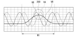
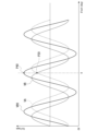
- FIG. 9 is a diagram showing an example of waveforms of the A-phase signal VA, B-phase signal VB, and R-phase signal VR in the first embodiment.
- the range W1 corresponds to the range of ⁇ degrees around 0 degrees of the estimated angle value ⁇ est shown in FIG.
- FIG. 10 is an enlarged view of the area indicated by numeral 200 in FIG.
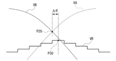
- the sub MPU 40 receives the estimated angle value ⁇ est from the main MPU 30 and calculates the instantaneous value Vr of the R-phase signal VR based on a predetermined function. causes a synchronization deviation ⁇ of the R-phase signal VR with respect to the A-phase signal VA and the B-phase signal VB.
- the out-of-synchronization ⁇ is a mechanical angle deviation between the intersection point P20 of the A-phase signal VA and the B-phase signal VB and the vertex P30 of the R-phase signal VR. It is desirable that the out-of-synchronization ⁇ is as small as possible.
- FIG. 11 is a block diagram schematically showing the configuration of a signal generation device 1A according to the second embodiment.
- the same reference numerals as those used in the first embodiment are assigned to configurations common to the first embodiment, and detailed description thereof will be omitted as appropriate.
- the signal generation device 1A includes a sensor section 10, a processing device 20A, a filter circuit 50A, and an output circuit 60A. Since the configuration of the sensor section 10 is the same as that of the first embodiment, the description of the sensor section 10 is omitted.
- the processing device 20A includes a main MPU 30A and a sub MPU 40A.
- the main MPU 30A calculates the angle information indicating the mechanical angle of the rotating shaft based on the magnetic flux detection signals Hu, Hv, and Hw output from the sensor unit 10, that is, the estimated angle value ⁇ est, and based on the calculated result of the estimated angle value ⁇ est. It matches the main MPU 30 of the first embodiment in that it generates the A-phase signal VA and the B-phase signal VB.
- the main MPU 30A differs from the main MPU 30 of the first embodiment in that it generates an R-phase signal VR in addition to the A-phase signal VA and B-phase signal VB.
- the sub MPU 40A matches the sub MPU 40 of the first embodiment in that it generates the C-phase signal VC and the D-phase signal VD based on the calculation result of the angle estimation value ⁇ est transmitted from the main MPU 30A.
- the sub MPU 40A differs from the sub MPU 40 of the first embodiment in that it does not generate the R-phase signal VR.
- the filter circuit 50A is similar to the filter circuit 50 of the first embodiment in that it includes a first low-pass filter 51, a second low-pass filter 52, a third low-pass filter 53, and a fourth low-pass filter 54. matches. On the other hand, the filter circuit 50A differs from the filter circuit 50 of the first embodiment in that the fifth low-pass filter 55 is not provided.
- the output circuit 60A includes a first differential output circuit 61, a second differential output circuit 62, a third differential output circuit 63, and a fourth differential output circuit 64, It matches the output circuit 60 of the first embodiment.
- the output circuit 60A includes a fifth differential output circuit 65A that generates a differential signal of the R-phase signal VR output from the main MPU 30A, instead of the fifth differential output circuit 65 of the first embodiment. It differs from the output circuit 60 of the first embodiment in that it is provided.
- the main MPU 30A is provided with an A/D converter 31, a timer 32, a first storage unit 34, a first D/A converter 35, and a first communication I/F 36. It matches the main MPU 30 in form.
- the main MPU 30A differs from the main MPU 30 of the first embodiment in that it includes a first arithmetic section 33A instead of the first arithmetic section 33 of the first embodiment.
- the main MPU 30A differs from the main MPU 30 of the first embodiment in that it further includes an arithmetic circuit 37, a switch 38, and an output port 39.
- the first calculation unit 33A has at least the same functions as the first calculation unit 33 of the first embodiment. That is, when the interrupt signal INT is input from the timer 32, the first calculation unit 33A calculates the angle estimated value ⁇ est based on the digital data of the magnetic flux detection signals Hu, Hv, and Hw input from the A/D converter 31. as angle information. The first calculation unit 33A generates the A-phase digital signal DVA and the B-phase digital signal DVB based on the calculation result of the estimated angle value ⁇ est and outputs them to the first D/A converter 35 when the interrupt process is executed. do.
- the first calculation unit 33A transmits digital data indicating the calculation result of the estimated angle value ⁇ est to the sub-MPU 40A via the first communication I/F 36 when executing the interrupt process. Since the function of the first arithmetic unit 33A as described above has been described in the first embodiment, the description in the second embodiment is omitted.
- the first calculation unit 33A has a function of controlling the switch 38 in addition to the functions described above.
- the arithmetic circuit 37 adds or multiplies the A-phase signal VA output from the first low-pass filter 51 and the B-phase signal VB output from the second low-pass filter 52 .
- arithmetic circuit 37 is an analog addition circuit or an analog multiplication circuit.
- the configurations of analog adder circuits and analog multiplier circuits are generally well known. Therefore, detailed description of the configuration of the arithmetic circuit 37 is omitted.
- the output port 39 is a port that outputs the output signal VR0 of the arithmetic circuit 37 as the R-phase signal VR.
- the output port 39 is electrically connected to the input terminal of the fifth differential output circuit 65A, and the R-phase signal VR output from the output port 39 is input to the fifth differential output circuit 65A. .
- the switch 38 electrically connects the arithmetic circuit 37 and the output port 39 when the mechanical angle indicated by the estimated angle value ⁇ est is greater than or equal to the first mechanical angle ⁇ 1 and less than or equal to the second mechanical angle ⁇ 2.
- the first calculator 33A turns on the switch 38 when the mechanical angle indicated by the estimated angle value ⁇ est is greater than or equal to the first mechanical angle ⁇ 1 and less than or equal to the second mechanical angle ⁇ 2.
- arithmetic circuit 37 and output port 39 are electrically connected, and output signal VR0 of arithmetic circuit 37 is output from output port 39 as R-phase signal VR.
- FIG. 12 is a diagram showing an example of waveforms of the A-phase signal VA, the B-phase signal VB, and the output signal VR0 of the arithmetic circuit 37 in the second embodiment.
- FIG. 12 shows a signal obtained by adding the A-phase signal VA and the B-phase signal VB as an example of the output signal VR0 of the arithmetic circuit 37.
- FIG. 12 shows a signal obtained by adding the A-phase signal VA and the B-phase signal VB as an example of the output signal VR0 of the arithmetic circuit 37.
- the mechanical angle indicated by the angle estimation value ⁇ est is 0 degrees
- the mechanical angle corresponding to the vertex P40 of the output signal VR0 of the arithmetic circuit 37 is the A-phase signal VA and the B-phase signal VB. substantially coincides with the mechanical angle corresponding to the intersection point P20 of . That is, by using the output signal VR0 of the arithmetic circuit 37 as the R-phase signal VR, the synchronization deviation ⁇ of the R-phase signal VR with respect to the A-phase signal VA and the B-phase signal VB can be suppressed to almost zero.
- the first calculation unit 33A turns on the switch 38 when the mechanical angle indicated by the estimated angle value ⁇ est is greater than or equal to the first mechanical angle ⁇ 1 and less than or equal to the second mechanical angle ⁇ 2. Control.
- the output signal VR0 of the arithmetic circuit 37 is output from the output port 39 as the R-phase signal VR only during the period in which the mechanical angle is equal to or greater than the first mechanical angle ⁇ 1 and equal to or less than the second mechanical angle ⁇ 2.
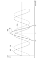
- FIG. 13 is a diagram showing an example of waveforms of the A-phase signal VA, the B-phase signal VB, and the R-phase signal VR output from the output port 39 in the second embodiment.
- the output signal VR0 of the arithmetic circuit 37 is output from the output port 39 as the R-phase signal VR only during the period in which the mechanical angle is equal to or greater than the first mechanical angle ⁇ 1 and equal to or less than the second mechanical angle ⁇ 2.
- an R-phase signal VR is obtained in which a symmetrical waveform appears once within a range of ⁇ degrees centered on 0 degrees.
- the first mechanical angle ⁇ 1 is set to 359.82422 (deg)
- 2 may be set to 0.17578 (deg).
- the signal generator 1A capable of reducing the synchronization deviation ⁇ of the R-phase signal VR with respect to the A-phase signal VA and the B-phase signal VB.
- the sub MPU 40A matches the sub MPU 40 of the first embodiment in that it includes a second communication I/F 41 and a second storage unit 43 .
- the sub-MPU 40A includes a second arithmetic unit 42A and a second D/A converter 44A instead of the second arithmetic unit 42 and the second D/A converter 44 of the first embodiment. It differs from the sub MPU 40 of the first embodiment.
- the second calculation unit 42A generates a C-phase digital signal DVC and a D-phase digital signal DVD based on the calculation result of the angle estimation value ⁇ est received from the main MPU 30A via the second communication I/F 41. 2 D/A converter 44A, which corresponds to the second computing unit 42 of the first embodiment.
- the second computing section 42A does not have the function of generating the instantaneous value Vr of the R-phase signal VR, that is, the R-phase digital signal DVR, based on a predetermined function such as a sigmoid function. It is different from the second computing section 42 of the embodiment.
- the second D/A converter 44A differs from the second D/A converter 44 of the first embodiment in that it is a 2-channel D/A converter.
- the second D/A converter 44A generates a C-phase signal VC by converting the C-phase digital signal DVC output from the second computing section 42A into an analog signal.
- the second D/A converter 44A generates a D-phase signal VD by converting the D-phase digital signal DVD output from the second computing section 42A into an analog signal.
- the second calculation unit 42A of the sub MPU 40A does not need to calculate the instantaneous value Vr of the R-phase signal VR based on a predetermined function. It is possible to reduce the calculation load (calculation time, memory size, etc.) of the unit 42A, improve real-time performance, and reduce the cost of the sub MPU 40A. Further, according to the second embodiment, since a 2-channel D/A converter can be used as the second D/A converter 44A of the sub MPU 40A, a 3-channel D/A converter can be used as the second D/A converter 44. Cost reduction of the sub MPU 40A can be realized as compared with the first embodiment.
- the processing device 20 includes the first processing device 30 that calculates the angle information and generates the A-phase signal VA and the B-phase signal VB based on the calculation result of the angle information; and the second processing device 40 that generates the C-phase signal VC, the D-phase signal VD, and the R-phase signal VR based on the calculation result of the angle information obtained from the one processing device 30 is illustrated.
- the present invention is not limited to this.
- the processing device calculates the angle information, and based on the calculation result of the angle information, the A-phase signal VA and A first processing device for generating the B-phase signal VB and a second processing device for generating the R-phase signal VR based on the calculation result of the angle information obtained from the first processing device.
- inexpensive general-purpose microcomputers having 2-channel D/A converters can be used as the first processing device and the second processing device.
- the processing device alone may generate the A-phase signal VA, B-phase signal VB and R-phase signal VR.
- the processing device alone can process A-phase signal VA, B-phase signal VB, C-phase signal VC, D-phase signal VD and R-phase signal. All signals of VR may be generated. If the R-phase signal VR is not needed, the processing units are a first processing unit that generates the A-phase signal VA and the B-phase signal VB, and a second processing unit that generates the C-phase signal VC and the D-phase signal VD. and may be provided.
- a low-cost general-purpose microcomputer having a two-channel D/A converter can be used as a processing device to generate the A-phase signals VA and A B-phase signal VB may be generated.
- the three magnetic sensors 11, 12 and 13 are used as examples. etc. may be changed as appropriate.
- FIG. 14 is a diagram schematically showing the appearance of an elevator 100 that is an application example of the present invention.
- the elevator 100 calculates a car 120 suspended by a rope 110, a hoist 130 that raises the car 120 by hoisting the rope 110, and angle information indicating the mechanical angle of the rotation shaft of the hoist 130, and calculates the angle information. and a signal generation device (not shown) that generates at least the first signal and the second signal based on the calculation result of .
- the signal generation device 1 of the first embodiment or the signal generation device 1A of the second embodiment can be used.
- Application examples of the present invention are not limited to the elevator 100, and the present invention can be widely applied to devices such as robots that are driven by motors.
- the present technology can be configured as follows.
- Angle information indicating the mechanical angle of the rotating shaft is calculated, and based on the result of the calculation of the angle information, the waveform of one cycle of the electrical angle appears N times (N is an integer equal to or greater than 1) in one cycle of the mechanical angle. 1 and a second signal having a phase difference of 90 electrical degrees with respect to the first signal.
- the signal generator according to (1) further comprising: a filter.
- the processing device Based on the calculation result of the angle information, the processing device generates a third signal in which a waveform of one electrical angle cycle appears once in one mechanical angle cycle, and an electrical angle
- the signal generation device according to any one of (1) to (3), further generating a fourth signal having a phase difference of 90 degrees at .
- a third low-pass filter provided in the transmission path of the third signal output from the processing device, and a fourth low-pass filter provided in the transmission path of the fourth signal output from the processing device.
- a third differential output circuit that generates a differential signal of the third signal output from the third low-pass filter and a differential signal of the fourth signal output from the fourth low-pass filter.
- the signal generation device according to (5), further comprising: a fourth differential output circuit that generates a differential signal.
- the processing device according to any one of (1) to (3), further generating a fifth signal indicating a reference position of one cycle of the mechanical angle based on the result of calculation of the angle information.
- the processing device calculates the angle information and generates the first signal and the second signal based on the calculation result of the angle information;
- the signal generation device according to (7), further comprising: a second processing device that generates the fifth signal based on a calculation result of the angle information obtained from the processing device.
- the processing device according to any one of (4) to (6), further generating a fifth signal indicating a reference position of one cycle of the mechanical angle based on the result of calculation of the angle information.
- a signal generator as described.
- the processing device includes a first processing device that calculates the angle information and generates the first signal and the second signal based on the calculation result of the angle information; (9), comprising a second processing device that generates the third signal, the fourth signal, and the fifth signal based on the calculation result of the angle information obtained from the processing device; A signal generator as described.
- the processing device includes an arithmetic circuit that adds or multiplies the first signal output from the first low-pass filter and the second signal output from the second low-pass filter; an output port for outputting the output signal of the arithmetic circuit as a fifth signal; and the arithmetic circuit when the mechanical angle indicated by the angle information is greater than or equal to a first mechanical angle and less than or equal to a second mechanical angle.
- (16) further comprising a plurality of magnetic sensors for detecting changes in magnetic flux due to rotation of the rotating shaft, wherein the processing device calculates the angle information based on signals output from the plurality of magnetic sensors;
- (17) Calculate the angle information indicating the mechanical angle of the car suspended by the rope, the hoist that raises the car by hoisting the rope, and the rotation shaft of the hoist, and calculate the result of the angle information. and a signal generator according to any one of (1) to (16) that generates at least the first signal and the second signal based on:
- a signal generation device capable of generating at least a first signal and a second signal with a simpler and lower cost configuration than a conventional optical encoder, and the signal generation device.
- An elevator is provided. Therefore, the present invention has industrial applicability.
Landscapes
- Physics & Mathematics (AREA)
- General Physics & Mathematics (AREA)
- Engineering & Computer Science (AREA)
- Automation & Control Theory (AREA)
- Computer Networks & Wireless Communication (AREA)
- Transmission And Conversion Of Sensor Element Output (AREA)
Priority Applications (4)
| Application Number | Priority Date | Filing Date | Title |
|---|---|---|---|
| US18/713,176 US20250020443A1 (en) | 2021-11-30 | 2022-11-29 | Signal generation device and elevator |
| JP2023565018A JPWO2023100886A1 (https=) | 2021-11-30 | 2022-11-29 | |
| CN202280078454.3A CN118318145A (zh) | 2021-11-30 | 2022-11-29 | 信号生成装置以及电梯 |
| EP22901318.0A EP4443112A4 (en) | 2021-11-30 | 2022-11-29 | SIGNAL GENERATION DEVICE AND LIFT |
Applications Claiming Priority (2)
| Application Number | Priority Date | Filing Date | Title |
|---|---|---|---|
| JP2021-194064 | 2021-11-30 | ||
| JP2021194064 | 2021-11-30 |
Publications (1)
| Publication Number | Publication Date |
|---|---|
| WO2023100886A1 true WO2023100886A1 (ja) | 2023-06-08 |
Family
ID=86612340
Family Applications (1)
| Application Number | Title | Priority Date | Filing Date |
|---|---|---|---|
| PCT/JP2022/044003 Ceased WO2023100886A1 (ja) | 2021-11-30 | 2022-11-29 | 信号生成装置およびエレベータ |
Country Status (5)
| Country | Link |
|---|---|
| US (1) | US20250020443A1 (https=) |
| EP (1) | EP4443112A4 (https=) |
| JP (1) | JPWO2023100886A1 (https=) |
| CN (1) | CN118318145A (https=) |
| WO (1) | WO2023100886A1 (https=) |
Citations (11)
| Publication number | Priority date | Publication date | Assignee | Title |
|---|---|---|---|---|
| JPS6370116A (ja) | 1986-09-12 | 1988-03-30 | Hitachi Ltd | 磁気式正弦波エンコ−ダの出力回路 |
| JPH07174588A (ja) * | 1993-11-29 | 1995-07-14 | Futaba Corp | 光学式アブソリュートスケール |
| JPH09218053A (ja) | 1996-02-08 | 1997-08-19 | Sankyo Seiki Mfg Co Ltd | 磁気式エンコーダ装置 |
| JPH11178303A (ja) * | 1997-12-09 | 1999-07-02 | Sankyo Seiki Mfg Co Ltd | エンコーダ装置及びそのパラメータ設定装置 |
| JP2000171239A (ja) * | 1998-12-03 | 2000-06-23 | Ntn Corp | 回転角検出装置 |
| JP2007071865A (ja) * | 2005-08-11 | 2007-03-22 | Mitsutoyo Corp | エンコーダ出力の内挿方法及び内挿回路 |
| JP2013205144A (ja) * | 2012-03-28 | 2013-10-07 | Nidec Sankyo Corp | エンコーダ装置および位置データの生成方法 |
| JP6233532B2 (ja) | 2014-12-22 | 2017-11-22 | 日本電産株式会社 | 位置推定方法および位置制御装置 |
| WO2021090372A1 (ja) * | 2019-11-05 | 2021-05-14 | 株式会社五十嵐電機製作所 | 汎用型ロータリーエンコーダ |
| WO2021186680A1 (ja) * | 2020-03-19 | 2021-09-23 | 三菱電機株式会社 | エレベーターの制御装置 |
| JP2021194064A (ja) | 2020-06-09 | 2021-12-27 | 株式会社大一商会 | 遊技機 |
Family Cites Families (4)
| Publication number | Priority date | Publication date | Assignee | Title |
|---|---|---|---|---|
| EP1741659B1 (en) * | 2004-04-30 | 2018-06-06 | Mitsubishi Denki Kabushiki Kaisha | Elevator apparatus |
| US20190003856A1 (en) * | 2015-12-18 | 2019-01-03 | Nidec Corporation | Motor module and motor authentication method |
| JP2017138143A (ja) * | 2016-02-02 | 2017-08-10 | Tdk株式会社 | 変位検出装置および角速度検出装置 |
| CN108426587B (zh) * | 2017-02-14 | 2020-09-18 | 日本电产三协株式会社 | 旋转编码器 |
-
2022
- 2022-11-29 JP JP2023565018A patent/JPWO2023100886A1/ja active Pending
- 2022-11-29 CN CN202280078454.3A patent/CN118318145A/zh active Pending
- 2022-11-29 US US18/713,176 patent/US20250020443A1/en active Pending
- 2022-11-29 EP EP22901318.0A patent/EP4443112A4/en active Pending
- 2022-11-29 WO PCT/JP2022/044003 patent/WO2023100886A1/ja not_active Ceased
Patent Citations (11)
| Publication number | Priority date | Publication date | Assignee | Title |
|---|---|---|---|---|
| JPS6370116A (ja) | 1986-09-12 | 1988-03-30 | Hitachi Ltd | 磁気式正弦波エンコ−ダの出力回路 |
| JPH07174588A (ja) * | 1993-11-29 | 1995-07-14 | Futaba Corp | 光学式アブソリュートスケール |
| JPH09218053A (ja) | 1996-02-08 | 1997-08-19 | Sankyo Seiki Mfg Co Ltd | 磁気式エンコーダ装置 |
| JPH11178303A (ja) * | 1997-12-09 | 1999-07-02 | Sankyo Seiki Mfg Co Ltd | エンコーダ装置及びそのパラメータ設定装置 |
| JP2000171239A (ja) * | 1998-12-03 | 2000-06-23 | Ntn Corp | 回転角検出装置 |
| JP2007071865A (ja) * | 2005-08-11 | 2007-03-22 | Mitsutoyo Corp | エンコーダ出力の内挿方法及び内挿回路 |
| JP2013205144A (ja) * | 2012-03-28 | 2013-10-07 | Nidec Sankyo Corp | エンコーダ装置および位置データの生成方法 |
| JP6233532B2 (ja) | 2014-12-22 | 2017-11-22 | 日本電産株式会社 | 位置推定方法および位置制御装置 |
| WO2021090372A1 (ja) * | 2019-11-05 | 2021-05-14 | 株式会社五十嵐電機製作所 | 汎用型ロータリーエンコーダ |
| WO2021186680A1 (ja) * | 2020-03-19 | 2021-09-23 | 三菱電機株式会社 | エレベーターの制御装置 |
| JP2021194064A (ja) | 2020-06-09 | 2021-12-27 | 株式会社大一商会 | 遊技機 |
Non-Patent Citations (1)
| Title |
|---|
| See also references of EP4443112A4 |
Also Published As
| Publication number | Publication date |
|---|---|
| CN118318145A (zh) | 2024-07-09 |
| JPWO2023100886A1 (https=) | 2023-06-08 |
| EP4443112A4 (en) | 2025-12-17 |
| US20250020443A1 (en) | 2025-01-16 |
| EP4443112A1 (en) | 2024-10-09 |
Similar Documents
| Publication | Publication Date | Title |
|---|---|---|
| JP5762622B2 (ja) | 角度検出装置 | |
| US5760562A (en) | Apparatus and method for generating digital position signals for a rotatable shaft | |
| US9857203B2 (en) | Resolver device | |
| CN110943670A (zh) | 一种电机转子位置获取方法及系统 | |
| JP7066306B2 (ja) | 回転角度検出装置、および当該回転角度検出装置を含む電動パワーステアリング装置 | |
| JP5217766B2 (ja) | 回転体の角度位置検出装置及び回転数検出装置 | |
| JP2005257565A (ja) | レゾルバディジタル角度変換装置および方法ならびにプログラム | |
| JP2013198229A (ja) | Δς変調型a/d変換器およびそれを備えたモータ制御装置 | |
| JP2013238431A (ja) | レゾルバ装置 | |
| WO2023100886A1 (ja) | 信号生成装置およびエレベータ | |
| Karabeyli et al. | Enhancing the accuracy for the open-loop resolver to digital converters | |
| JP7789770B2 (ja) | 角度検出方法および角度検出装置 | |
| JP7819187B2 (ja) | 角度検出方法および角度検出装置 | |
| US20150022131A1 (en) | Electric circuit and method for estimating the angular position of a rotor of an electric motor, and device for controlling an electric motor | |
| KR102077362B1 (ko) | 모터제어기의 개선 | |
| JP2016020819A (ja) | 角度検出装置及びモータ駆動回路 | |
| JP7186846B1 (ja) | 角度検出装置及び交流回転機の制御システム | |
| JP2016148587A (ja) | レゾルバ信号処理装置 | |
| JP2010014410A (ja) | 回転体の回転位置検出装置 | |
| JP2024006075A (ja) | 通信方法および通信システム | |
| CN113302455B (zh) | 旋转角度检测装置以及包含该旋转角度检测装置的电动助力转向装置 | |
| WO2024004474A1 (ja) | 角度検出装置および角度検出方法 | |
| JP5097012B2 (ja) | エンコーダ用信号処理回路 | |
| WO2014010063A1 (ja) | モータ制御装置 | |
| JP2006250618A (ja) | 速度検出装置 |
Legal Events
| Date | Code | Title | Description |
|---|---|---|---|
| 121 | Ep: the epo has been informed by wipo that ep was designated in this application |
Ref document number: 22901318 Country of ref document: EP Kind code of ref document: A1 |
|
| ENP | Entry into the national phase |
Ref document number: 2023565018 Country of ref document: JP Kind code of ref document: A |
|
| WWE | Wipo information: entry into national phase |
Ref document number: 18713176 Country of ref document: US |
|
| WWE | Wipo information: entry into national phase |
Ref document number: 202280078454.3 Country of ref document: CN |
|
| WWE | Wipo information: entry into national phase |
Ref document number: 2022901318 Country of ref document: EP |
|
| NENP | Non-entry into the national phase |
Ref country code: DE |
|
| ENP | Entry into the national phase |
Ref document number: 2022901318 Country of ref document: EP Effective date: 20240701 |