WO2023100503A1 - 電子部品用ペースト - Google Patents
電子部品用ペースト Download PDFInfo
- Publication number
- WO2023100503A1 WO2023100503A1 PCT/JP2022/038492 JP2022038492W WO2023100503A1 WO 2023100503 A1 WO2023100503 A1 WO 2023100503A1 JP 2022038492 W JP2022038492 W JP 2022038492W WO 2023100503 A1 WO2023100503 A1 WO 2023100503A1
- Authority
- WO
- WIPO (PCT)
- Prior art keywords
- binder
- cellulose
- dispersant
- ethyl cellulose
- terminal
- Prior art date
- Legal status (The legal status is an assumption and is not a legal conclusion. Google has not performed a legal analysis and makes no representation as to the accuracy of the status listed.)
- Ceased
Links
Images

Classifications
-
- C—CHEMISTRY; METALLURGY
- C08—ORGANIC MACROMOLECULAR COMPOUNDS; THEIR PREPARATION OR CHEMICAL WORKING-UP; COMPOSITIONS BASED THEREON
- C08L—COMPOSITIONS OF MACROMOLECULAR COMPOUNDS
- C08L1/00—Compositions of cellulose, modified cellulose or cellulose derivatives
- C08L1/08—Cellulose derivatives
-
- C—CHEMISTRY; METALLURGY
- C08—ORGANIC MACROMOLECULAR COMPOUNDS; THEIR PREPARATION OR CHEMICAL WORKING-UP; COMPOSITIONS BASED THEREON
- C08K—Use of inorganic or non-macromolecular organic substances as compounding ingredients
- C08K3/00—Use of inorganic substances as compounding ingredients
-
- C—CHEMISTRY; METALLURGY
- C08—ORGANIC MACROMOLECULAR COMPOUNDS; THEIR PREPARATION OR CHEMICAL WORKING-UP; COMPOSITIONS BASED THEREON
- C08K—Use of inorganic or non-macromolecular organic substances as compounding ingredients
- C08K3/00—Use of inorganic substances as compounding ingredients
- C08K3/01—Use of inorganic substances as compounding ingredients characterized by their specific function
- C08K3/013—Fillers, pigments or reinforcing additives
-
- C—CHEMISTRY; METALLURGY
- C08—ORGANIC MACROMOLECULAR COMPOUNDS; THEIR PREPARATION OR CHEMICAL WORKING-UP; COMPOSITIONS BASED THEREON
- C08K—Use of inorganic or non-macromolecular organic substances as compounding ingredients
- C08K3/00—Use of inorganic substances as compounding ingredients
- C08K3/02—Elements
- C08K3/08—Metals
-
- H—ELECTRICITY
- H01—ELECTRIC ELEMENTS
- H01B—CABLES; CONDUCTORS; INSULATORS; SELECTION OF MATERIALS FOR THEIR CONDUCTIVE, INSULATING OR DIELECTRIC PROPERTIES
- H01B1/00—Conductors or conductive bodies characterised by the conductive materials; Selection of materials as conductors
- H01B1/20—Conductive material dispersed in non-conductive organic material
- H01B1/22—Conductive material dispersed in non-conductive organic material the conductive material comprising metals or alloys
-
- H—ELECTRICITY
- H01—ELECTRIC ELEMENTS
- H01G—CAPACITORS; CAPACITORS, RECTIFIERS, DETECTORS, SWITCHING DEVICES, LIGHT-SENSITIVE OR TEMPERATURE-SENSITIVE DEVICES OF THE ELECTROLYTIC TYPE
- H01G4/00—Fixed capacitors; Processes of their manufacture
- H01G4/002—Details
- H01G4/005—Electrodes
- H01G4/008—Selection of materials
-
- H—ELECTRICITY
- H01—ELECTRIC ELEMENTS
- H01G—CAPACITORS; CAPACITORS, RECTIFIERS, DETECTORS, SWITCHING DEVICES, LIGHT-SENSITIVE OR TEMPERATURE-SENSITIVE DEVICES OF THE ELECTROLYTIC TYPE
- H01G4/00—Fixed capacitors; Processes of their manufacture
- H01G4/30—Stacked capacitors
-
- C—CHEMISTRY; METALLURGY
- C08—ORGANIC MACROMOLECULAR COMPOUNDS; THEIR PREPARATION OR CHEMICAL WORKING-UP; COMPOSITIONS BASED THEREON
- C08L—COMPOSITIONS OF MACROMOLECULAR COMPOUNDS
- C08L2203/00—Applications
- C08L2203/20—Applications use in electrical or conductive gadgets
-
- C—CHEMISTRY; METALLURGY
- C08—ORGANIC MACROMOLECULAR COMPOUNDS; THEIR PREPARATION OR CHEMICAL WORKING-UP; COMPOSITIONS BASED THEREON
- C08L—COMPOSITIONS OF MACROMOLECULAR COMPOUNDS
- C08L2205/00—Polymer mixtures characterised by other features
- C08L2205/02—Polymer mixtures characterised by other features containing two or more polymers of the same C08L -group
Definitions
- the present invention relates to a paste for electronic parts containing inorganic particles, a dispersant, a binder and an organic solvent, which is used in the manufacture of electronic parts, and particularly relates to improvement of the binder.
- Patent Document 1 Japanese Patent Application Laid-Open No. 2018-168238
- This conductive paste contains a conductive powder, an organic resin (hereinafter referred to as a "binder"), an organic solvent, an additive, and a dielectric powder.
- the agent comprises a composition containing an unsaturated carboxylic acid-based dispersant and an oleylamine-based dispersant.
- nickel powder is exemplified as the conductive powder
- ceramic powder is exemplified as the dielectric powder.
- the content of the unsaturated carboxylic acid-based dispersant in the additive is 0.2% by mass or more and 1.2% by mass or less with respect to the total amount of the conductive paste, and The content of the oleylamine-based dispersant in the additive is 0.3% by mass or more and 2.0% by mass or less with respect to the total amount of the conductive paste.
- cellulose is known to have a hydroxy group on one non-reducing end side and a hydroxy group and a formyl group on the other reducing end side.
- ethyl cellulose as the binder described above it can be easily assumed that most of the terminal hydroxy groups are ethoxylated due to the known manufacturing process. Therefore, it can be said that one terminal of normal ethyl cellulose (corresponding to the non-reducing terminal side of cellulose) is an ethoxy group, and the other terminal (corresponding to the reducing terminal side of cellulose) is an ethoxy group or a formyl group.
- Common dispersants have alkyl chains, ether chains, or ester chains, so their adhesion to ethyl cellulose is weak.
- ethyl cellulose as a binder is adsorbed to inorganic particles such as nickel particles and ceramic particles, and some ethyl cellulose is not adsorbed to any inorganic particles.
- the adhesive force at the interface between the dispersant adsorbed on the surface of the inorganic particles and the ethyl cellulose that is not adsorbed is weakened, and as a result, between the inorganic particles in the conductive paste, more specifically, the nickel particles Adhesion between particles, between ceramic particles, or between nickel particles and ceramic particles is weakened. This tends to cause cohesive failure (separation within the internal electrode layer) between nickel particles in the internal electrodes, between ceramic particles, or between nickel particles and ceramic particles during the manufacturing process of the multilayer ceramic capacitor.
- Cohesive failure in the internal electrodes includes peeling of the internal electrode layers during pressure cutting of the laminate before firing, delamination of the multilayer ceramic capacitor after firing, and deterioration of the moisture resistance of the multilayer ceramic capacitor after baking the external electrodes. In order to cause it, it is required to prevent it from occurring as much as possible.
- the conductive paste does not contain a dispersant, it is possible to eliminate interfaces with weak adhesion. However, it is difficult to ensure the dispersibility of the conductive paste without a dispersant.
- an object of the present invention is to provide an electronic component paste that can satisfy the above-mentioned demands.
- the present invention is directed to a paste for electronic parts containing inorganic particles, a dispersant, a binder, and an organic solvent, wherein the binder comprises a first binder adsorbed to the surface of the inorganic particles, and a second binder that is not adsorbed to the surface of the polymer, wherein at least the first binder is a cellulose derivative having one terminal carboxyl group or one terminal carboxylate.
- the inorganic particles Even if the adhesive force at the interface between the dispersant adsorbed on the surface of the inorganic particles and the second binder not adsorbed on the inorganic particles is low, the inorganic particles The interface between the cellulose derivative having one terminal carboxyl group or one terminal carboxylate as the first binder adsorbed on the surface of the inorganic particles and the second binder not adsorbed on the surface of the inorganic particles exhibits high adhesive strength at the interface. . As a result, as a whole, the adhesive strength between the inorganic particles is improved through the high adhesive strength at the interface between the first binder and the second binder as described above. Therefore, when the present invention is applied, for example, to a conductive paste for internal electrodes used in the manufacture of laminated ceramic capacitors, cohesive failure ( peeling in the internal electrode layers) can be made less likely to occur.
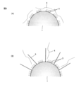
- an inorganic substance 1 is a diagram schematically showing a state in which a dispersing agent 2 and a first binder 5 are adsorbed to particles 1.
- FIG. It is for explaining the action of the electronic component paste according to the present invention, in the case where the low-molecular dispersant 3 is included, (A) the state in which only the dispersant 3 is adsorbed on the inorganic particles 1, (B) the inorganic particles 1 FIG.
- FIG. 2 is a diagram schematically showing a state in which a dispersant 3 and a first binder 5 are adsorbed to the surface.
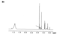
- FIG. 1 shows 1 H-NMR spectra of ethyl cellulose derivatized products.
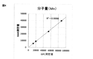
- FIG. 2 is a diagram showing the correlation between the molecular weight of ethyl cellulose determined by NMR and that determined by GPC.
- the electronic component paste according to the present invention contains inorganic particles, a dispersant, a binder, and an organic solvent.
- the binder includes a first binder adsorbed on the surfaces of the inorganic particles and a second binder not adsorbed on the surfaces of the inorganic particles.
- At least the first binder is a cellulose derivative having one terminal carboxyl group or one terminal carboxylate.
- the cellulose derivative having one terminal carboxyl group or one terminal carboxylate as the first binder is the steric repulsion part of the dispersant (side chain in the case of a comb-type dispersant, main It is noted that the size is several tens to several hundred nm longer than the chain).
- Generally commercially available cellulose derivatives have a polystyrene equivalent molecular weight Mn of about 10000 to 90000 and a size of about 25 to 225 nm.
- the dispersant generally adheres to the particle surface and has a molecular chain of several nanometers (the length of the side chain in the case of a polymer dispersant and the length of the main chain in the case of a low-molecular dispersant). ), wetting with the solvent and dispersion stabilization due to steric repulsion are realized.
- the interface between the sterically repulsive portion of several nanometers in the dispersant (the side chain in the case of a comb-shaped dispersant and the main chain in the case of a one-end adsorption dispersant) and the binder is poorly compatible. A problem arises in that the adhesive strength becomes low.
- a comb-shaped polymeric dispersant (hereinafter referred to as “polymeric dispersant”) 2 is adsorbed on the surface of inorganic particles 1 .
- a low-molecular one-end adsorption dispersant (hereinafter referred to as “low-molecular-weight dispersant”) 3 is adsorbed on the surface of inorganic particles 1 .
- the second binder 4 made of a cellulose derivative Adhesion between the binder and the molecular chains of dispersant 2 or 3 is difficult to develop (poor compatibility).
- a steric repulsion portion (comb) of the dispersant 2 or 3 is formed in the gap where the dispersant 2 or 3 is not adsorbed on the surface of the inorganic particles 1.
- the side chain in the case of a single-end adsorption dispersant such as the low-molecular dispersant 3, the main chain) is longer than the main chain).
- the molecular chains are arranged at wide intervals, so that steric restrictions are less likely to occur, and the second binder 4 and the first binder 5 are separated. is oriented and the adhesive force is likely to develop.
- the binder that is adsorbed on the surfaces of the inorganic particles is defined as the "first binder”
- the binder that is not adsorbed on the surfaces of the inorganic particles is defined as the "second binder”. Therefore, the second binder can be a binder of the same composition as the first binder, ie both are cellulose derivatives with one terminal carboxyl group or one terminal carboxylate.
- the second binder may be a cellulose derivative that does not have a single terminal carboxyl group or a single terminal carboxylate.
- the second binder is a copolymer having a portion of a cellulose derivative (any end is acceptable) or a mixture of multiple polymers containing a cellulose derivative.
- a high intermolecular force acts between the one-end adsorbed cellulose derivative in the first binder and the cellulose derivative part of the second binder on the surface of the , and a high adhesive strength improvement effect is obtained.
- the inorganic particle surface adsorption rate of the cellulose derivative having one terminal carboxyl group or one terminal carboxylate does not reach 100%. This is because the adsorption phenomenon is not completely irreversible because of single-point adsorption.
- the inorganic particle surface adsorption rate varies depending on the chemical state and surface area of the inorganic particle surface, the type of solvent contained in the electronic component paste, the amount and concentration of the binder added in the electronic component paste, and the like. About 30 to 90% of the added amount is adsorbed in the region where the amount is not excessive.
- the binder does not contain a cellulose derivative having one terminal carboxyl group or one terminal carboxylate, as shown in FIGS.
- the interface between the dispersing agent 2 or 3 adsorbed to the inorganic particles 1 and the second binder 4 made of, for example, a cellulose derivative and not adsorbed to the inorganic particles 1 is mainly an interface having only a low adhesive strength.
- the binder contains the first binder 5 made of a cellulose derivative having one terminal carboxyl group or one terminal carboxylate, as shown in FIGS. 1(B) and 2(B), inorganic particles 1 and the second binder 4 made of, for example, a cellulose derivative that is not adsorbed on the surface of the inorganic particles 1.
- the cellulose derivative having one terminal carboxyl group or one terminal carboxylate as the first binder is 1.0 mg/m 2 to 5.0 mg/m 2 with respect to the total surface area of the inorganic particles. is preferred. In other words, 1.0 mg/m 2 to 5.0 mg/m 2 of the cellulose derivative having one terminal carboxyl group or one terminal carboxylate as the first binder is adsorbed to the total surface area of the inorganic particles. is preferred. This is because a significant effect appears when the adsorption amount becomes 1.0 mg/m 2 or more. On the other hand, there is almost no adsorption exceeding 5.0 mg/m 2 .
- the cellulose derivative having one terminal carboxyl group or one terminal carboxylate is preferably a cellulose ether having one terminal carboxyl group or one terminal carboxylate. This is because it is more realistic to obtain a cellulose ether having a single terminal carboxyl group or a single terminal carboxylate as a cellulose derivative having a single terminal carboxyl group or a single terminal carboxylate when considering the synthetic reaction scheme described later. be.
- the cellulose ether having one terminal carboxyl group or one terminal carboxylate is more preferably at least one selected from methylcellulose, ethylcellulose, hydroxyethylcellulose, hydroxypropylcellulose, ethylhydroxyethylcellulose and hydroxypropylmethylcellulose.
- a comb-shaped polymer dispersant or a low-molecular one-end adsorption dispersant is used, as described above.
- a comb-shaped polymeric dispersant for example, a polycarboxylic acid-based dispersant is used.
- Comb-type polymer dispersants such as polycarboxylic acid-based dispersants and low-molecular one-end adsorption dispersants form steric repulsion sites by arranging molecular chains at narrow intervals on the surface of inorganic particles, resulting in steric restrictions.
- the inorganic particles contained in the electronic component paste according to the present invention preferably contain at least one of ceramic particles and metal particles.
- a paste for forming dielectric layers in a multilayer ceramic capacitor contains at least ceramic particles
- a paste for forming internal electrode layers contains at least metal particles.
- the ceramic particles described above contain at least one element selected from, for example, Ba, Ti, Ca, Zr and Sr.
- the metal particles described above contain, for example, at least one metal selected from Cu, Ni, Au and Ag.
- the TMS derivatization method is a method of substituting a trimethylsilyl group (Si(CH 3 ) 3 ) for H of a hydroxyl group contained in a carboxyl group of ethyl cellulose. Due to this derivatization, the number of hydrogen atoms in the carboxyl group is changed from 1H to 9H, so the detection sensitivity in 1 H-NMR is increased ninefold.
- a derivatized product is obtained by adding ethyl cellulose and a derivatizing reagent (BSTFA) to a dehydrated chloroform solvent and heating at 70° C. for 1 hour. Since the derivatization reagent acts on both hydroxyl groups and carboxyl groups of ethyl cellulose, the amount of reagent to be added was about 1.5 times the molar number of hydroxyl groups and terminal carboxyl groups of ethyl cellulose. In addition, it was confirmed that the quantitative values of TMS hydroxyl groups and carboxyl groups did not change even when the amount of the reagent was added in excess of 1.5 times the molar amount.
- BSTFA derivatizing reagent
- the number of carboxyl groups in ethyl cellulose decreases as the molecular weight increases, suggesting that the carboxyl groups are present in sites that depend on the molecular weight. Since the terminal concentration of the polymer decreases as the molecular weight of one molecular chain increases, it is considered that the quantified carboxyl groups are present at the terminal. From the aspect of the synthesis reaction scheme of the sample, it can be determined that the carboxyl group analyzed by NMR exists at one end.
- the molecular weight of ethyl cellulose was calculated by determining the number of repetitions of ethyl cellulose.
- Table 2 shows the average molecular weight determined by NMR and the average molecular weight determined by GPC.
- the average molecular weight determined by GPC is in terms of polystyrene
- the average molecular weight determined by NMR does not match the average molecular weight determined by GPC in absolute value.
- FIG. 4 when the molecular weight values obtained by both methods were compared for samples with different molecular weights, a high correlation was shown. This result indicates that a carboxyl group exists at one end of ethyl cellulose, and it can be said that NMR quantified the carboxyl group present at one end.
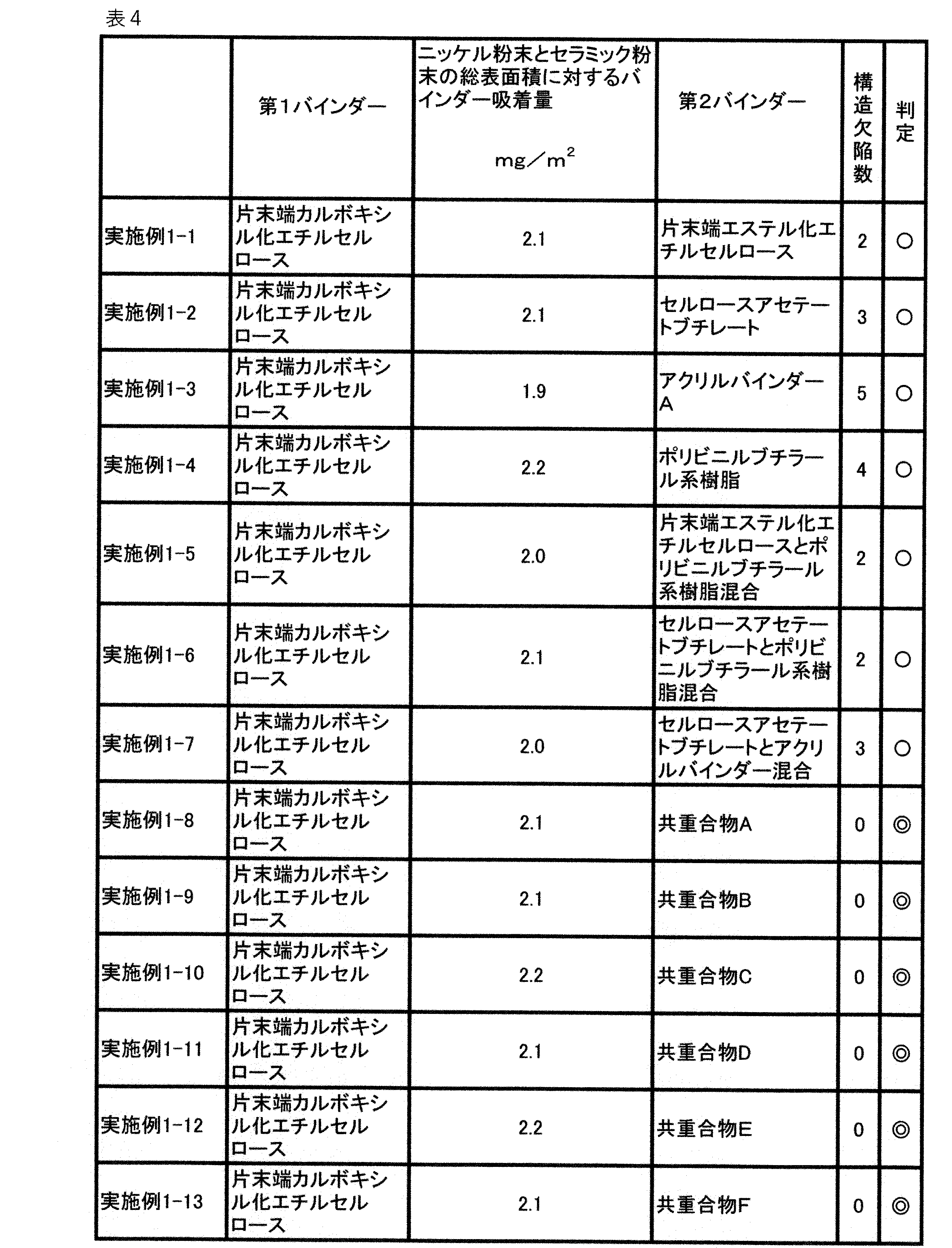
- the intermediate conductive paste shown in the "second binder" column of Tables 3 and 4, - Single-end esterified ethyl cellulose, - cellulose acetate butyrate, - Acrylic binder A (a binder made of polyisobutyl methacrylate), ⁇ Polyvinyl butyral resin, ⁇ Mixing of one-end esterified ethyl cellulose and polyvinyl butyral resin, ⁇ Mixing of cellulose acetate butyrate and polyvinyl butyral resin, - Mixing of cellulose acetate butyrate and acrylic binder A, - Copolymer A (details will be described later), - Copolymer B (details will be described later), ⁇ Copolymer C (details will be described later), - Copolymer D (details will be described later), Copolymer E (details will be described later), and Copolymer F (details will be described later), 1.1 parts by
- the dispersion method is not limited to the above method, and various methods such as roll mill, ball mill, bead mill, and high-pressure dispersion can be applied. This applies not only to the operation for obtaining the conductive paste here, but also to other operations.
- Copolymer A is a copolymer of one-end carboxylated ethyl cellulose and acrylic binder B (main monomer is isobutyl methacrylate and contains 5 mol % of 2-hydroxyethyl methacrylate).
- azoisobutyronitrile (AIBN) as a polymerization initiator for the introduced methacrylate (with the total number of moles of one-end carboxylated ethyl cellulose and acrylic binder B converted to Mn being 1 mol) was mixed to obtain 70 C. for 5 hours to obtain a binder solution containing copolymer A.
- Copolymer B is a copolymer of one-end-esterified ethyl cellulose and polyvinyl butyral resin.
- the resulting solution was added with 1.5 mol of methacrylic acid and 1.5 mol of diisopropylcarbodiimide as a condensing agent (assuming that the total number of moles of one-end-esterified ethyl cellulose and polyvinyl acetal-based resin in terms of Mn is 1 mol).
- dimethylaminopyridine as a reaction accelerator was added in an amount of 0.01 times the number of moles of the condensing agent, and the mixture was stirred at a temperature of 50°C for 24 hours to carry out a reaction. This led to the introduction of methacrylate into the hydroxyl groups of one-end-esterified ethyl cellulose and polyvinyl acetal-based resins.
- azoisobutyronitrile AIBN
- methacrylate the total number of moles of one-end-esterified ethyl cellulose and polyvinyl acetal resin converted to Mn being 1 mol.
- a reaction was carried out at 70° C. for 5 hours to obtain a binder solution containing copolymer B.
- Copolymer C is a copolymer of one-end carboxylated ethyl cellulose and polyvinyl butyral resin.
- the resulting solution was added with 1.5 mol of methacrylic acid and 2.0 mol of diisopropylcarbodiimide as a condensing agent (where the total number of moles of one-end carboxylated ethyl cellulose and polyvinyl acetal-based resin in terms of Mn is 1 mol). and dimethylaminopyridine as a reaction accelerator in an amount 0.01 times the number of moles of the condensing agent were added, and the mixture was stirred at a temperature of 50° C. for 24 hours to carry out a reaction.
- methacrylate is introduced into the hydroxy groups of the one-end carboxylated ethyl cellulose and the polyvinyl acetal-based resin, and the hydroxy groups of the polyvinyl acetal-based resin and the one-end carboxylated ethyl cellulose are esterified with the carboxyl groups of the one-end carboxylated ethyl cellulose. and proceeded.
- azoisobutyronitrile AIBN
- methacrylate the total number of moles of one-end carboxylated ethyl cellulose and polyvinyl acetal resin converted to Mn being 1 mol.
- a reaction was carried out at 70° C. for 5 hours to obtain a binder solution containing copolymer C.
- Copolymer D is a copolymer of one-end carboxylated ethyl cellulose and polyvinyl butyral resin.
- a binder solution containing polyvinyl acetal-based resin and a copolymer D obtained by esterification of the hydroxyl group of the one-end carboxylated ethyl cellulose and the carboxyl group of the one-end carboxylated ethyl cellulose was obtained.
- Copolymer E is a copolymer of cellulose acetate butyrate and polyvinyl butyral resin.
- the resulting solution was added with 2 mol of methacrylic acid (where the total number of moles of cellulose acetate butyrate and polyvinyl acetal-based resin in terms of Mn is 1 mol), 2 mol of diisopropylcarbodiimide as a condensing agent, and a reaction accelerator. Then, dimethylaminopyridine was added in an amount 0.01 times the molar amount of the condensing agent, and the mixture was stirred at a temperature of 50° C. for 24 hours to carry out a reaction. This led to the introduction of methacrylate into cellulose acetate butyrate and polyvinyl acetal resins.
- Copolymer F is a copolymer of cellulose acetate butyrate and acrylic binder B (main monomer is isobutyl methacrylate and contains 5 mol % of 2-hydroxyethyl methacrylate).
- cellulose acetate butyrate (“CAB381-0.1” manufactured by Eastman) having a number average molecular weight Mn of 2.0 ⁇ 10 4 and the above-mentioned 5.5 parts by mass of acrylic binder B was dried under reduced pressure, 89 parts by mass of dihydroterpineol acetate was added, and dissolved at 50° C. in a nitrogen atmosphere. The resulting solution was added with 2 mol of methacrylic acid (where the total number of moles of cellulose acetate butyrate and polyvinyl acetal-based resin in terms of Mn is 1 mol), 2 mol of diisopropylcarbodiimide as a condensing agent, and a reaction accelerator.
- methacrylic acid where the total number of moles of cellulose acetate butyrate and polyvinyl acetal-based resin in terms of Mn is 1 mol
- diisopropylcarbodiimide as a condensing agent
- dimethylaminopyridine was added in an amount 0.01 times the molar amount of the condensing agent, and the mixture was stirred at a temperature of 50° C. for 24 hours to carry out a reaction. In this way, introduction of methacrylate into cellulose acetate butyrate and acrylic binder B was advanced.
- azoisobutyronitrile (AIBN) as a polymerization initiator for the introduced methacrylate (the total number of moles of cellulose acetate butyrate and polyvinyl acetal-based resin in terms of Mn being 1 mol) was mixed to obtain 70 C. for 5 hours to obtain a binder solution containing copolymer F.
- AIBN azoisobutyronitrile
- the amount of binder adsorption relative to the total surface area of nickel powder and ceramic powder was obtained.
- Amount of adsorbed binder (total amount of organic solids - total amount of organic solids in supernatant - total amount of dispersant) / total surface area of nickel powder and ceramic powder. Since it is used, it is in an adsorption state that can be regarded as substantially irreversible, and the calculation was made on the assumption that the supernatant does not contain the dispersant.
- binder adsorption amounts are shown in Tables 3 and 4 in the column "Binder adsorption amount with respect to the total surface area of nickel powder and ceramic powder".
- the mixture was centrifuged (“CS100FNX” manufactured by himac) for 15 minutes at 29000 rpm to precipitate nickel powder and ceramic powder, and the supernatant was collected.
- the collected supernatant was dried, and the dried solid content of the obtained supernatant was converted to TMS and subjected to NMR measurement to identify the adsorbent binder.
- fractionation by HPLC is required.
- this ceramic slurry was formed on a PET (polyethylene terephthalate) film using a doctor blade method so as to have a thickness of 1.0 ⁇ m after drying to obtain a ceramic green sheet.
- a pattern was formed on the ceramic green sheet so that the chip-shaped laminated body to be obtained later after cutting and firing had a planar dimension of 1.0 mm ⁇ 0.5 mm.
- Conductive paste according to the above sample so that 30 ⁇ m (X-ray fluorescence analysis (XRF) measurement) and an average physical thickness of 0.60 ⁇ m (focused ion beam (FIB) processing cross-section scanning electron microscope (SEM) observation) It was printed by a screen printer to form a conductive paste coating film to serve as an internal electrode.
- XRF X-ray fluorescence analysis
- FIB focused ion beam
- SEM scanning electron microscope
- the column “number of structural defects" in Tables 3 and 4 shows the number of laminate chips in which structural defects were observed among the 100 laminate chips. Based on the number of laminate chips in which structural defects were observed, occurrence of structural defects was evaluated according to the following criteria.
- High-molecular-weight comb-type dispersants such as polycarboxylic acid-based dispersants and low-molecular-weight single-end-adsorbed dispersants form steric repulsion sites by arranging molecular chains at narrow intervals on the surface of inorganic particles. Due to restrictions, there is a problem that it is difficult to develop an adhesive force (poor compatibility) between the binder and the molecular chains of the dispersant.
- Examples 1-5 to 1-7 and Examples 1-8 to 1-13 it was found that, as in Examples 1-5 to 1-7, the cellulose derivative was mixed and included, and the As in Examples 1-8 to 1-13, it is found that the use of a copolymer having a cellulose derivative portion as a binder is more effective in suppressing structural defects. This is presumed to be due to the fact that in the different binder mixed systems such as those of Examples 1-5 to 1-7, the adhesion at the interfaces of the different binders was weak, and cohesive failure (peeling within the internal electrode layers) occurred starting there. be done.
- the cellulose derivative having a higher Tg than the composition of only the cellulose derivative having a high Tg (glass transition point) and a different binder having a low Tg is softer and less likely to break.
- the adsorption amount of one-end carboxylated ethyl cellulose to the total surface area of nickel powder and ceramic powder is particularly preferably 1.0 mg/m 2 or more and 5.0 mg/m 2 or less.
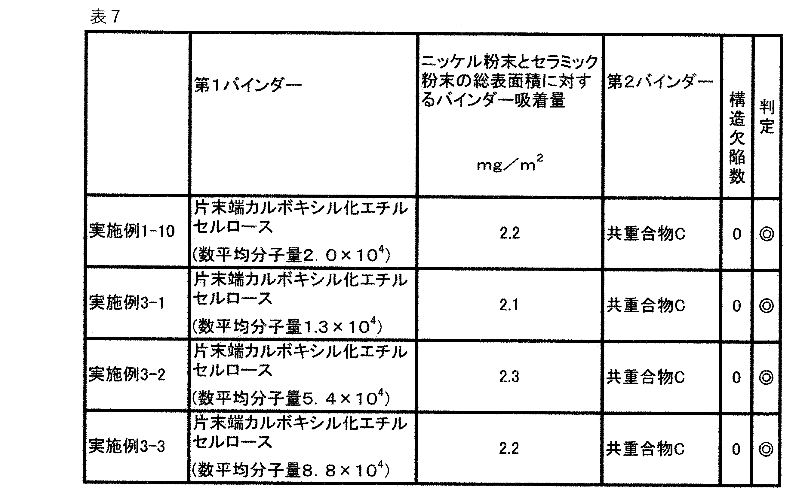
- the reason why the adsorbed amount did not change significantly even when the molecular weight was changed is that the shorter the molecular chain of the one-end carboxylated ethyl cellulose, the smaller the repulsion between the molecular chains adsorbed on the surfaces of the nickel particles and the ceramic particles.
- the number of adsorbed single-end carboxylated ethyl cellulose increased, the longer the molecular chain of the single-end carboxylated ethyl cellulose, the greater the repulsion between the molecular chains adsorbed on the surfaces of the nickel particles and the ceramic particles, resulting in single-end carboxylation. It is presumed that there is a balance relationship such that the number of adsorbed ethyl cellulose decreases.
- this ceramic slurry was formed on a PET (polyethylene terephthalate) film using a doctor blade method so as to have a thickness of 1.0 ⁇ m after drying to obtain a ceramic green sheet.
- the conductive paste according to Example 1-10 described above is printed by a screen printer, and the conductive paste to be the internal electrode is printed. A flexible paste coating was formed.
- the ceramic paste according to Example 4-2 shown in Table 8 was applied to the place where the conductive paste coating film was not formed by a screen printing machine so that the average physical thickness was 0.30 ⁇ m (FIB processed cross-sectional SEM observation). and formed a coating film for compensating for a step due to the thickness of the conductive paste coating film to be the internal electrode.
- Example 4-1 [Evaluation of Occurrence of Structural Defects]
- Example 4-1 the same method as in Example 1 was used to evaluate the amount of binder adsorption with respect to the total surface area of the nickel powder and ceramic powder, and to evaluate the number of structural defects when the unfired laminate was cut. bottom.
- Example 4-2 for each of 100 unfired laminate chips randomly selected from the above-described unfired laminate chips, the cut surface of the press cutting was observed with an optical microscope, and structural defects were identified. The presence or absence of cohesive failure (peeling within the internal electrode layer or within the step compensation coating) in the conductive paste coating or in the step compensation coating was confirmed.
- the column “number of structural defects” in Table 8 shows the number of laminate chips in which structural defects were observed among 100 laminate chips. Also, the “determination” in Table 8 follows the same criteria as the “determination” in Tables 3 and 4.
- the inorganic particles contained in the electronic component paste may be any inorganic particles as long as they can adsorb a cellulose derivative having a one-end carboxyl group or a one-end carboxylate. I understand.
Landscapes
- Chemical & Material Sciences (AREA)
- Engineering & Computer Science (AREA)
- Polymers & Plastics (AREA)
- Health & Medical Sciences (AREA)
- Organic Chemistry (AREA)
- Medicinal Chemistry (AREA)
- Chemical Kinetics & Catalysis (AREA)
- Power Engineering (AREA)
- Microelectronics & Electronic Packaging (AREA)
- Manufacturing & Machinery (AREA)
- Spectroscopy & Molecular Physics (AREA)
- Dispersion Chemistry (AREA)
- Physics & Mathematics (AREA)
- Materials Engineering (AREA)
- Conductive Materials (AREA)
- Ceramic Capacitors (AREA)
- Compositions Of Macromolecular Compounds (AREA)
Abstract
Description
[セルロース誘導体の合成]
この実験例において、電子部品用ペーストに含まれるバインダーとなるべき片末端カルボキシル化セルロース誘導体および片末端エステル化セルロース誘導体を明らかにするため、以下に各々の合成方法を示す。以下に示した合成方法は、セルロース誘導体の一種であり、電子部品用ペーストなどで広く用いられているエチルセルロースでの合成方法である。なお、これらの合成方法は、一例にすぎず、これらに限定されるものではない。
(1)セルロースの還元末端の酸化反応による片末端カルボキシル化セルロースの生成
セルロースの水分散スラリー(固形分1440g)に、50%水酸化ナトリウム水溶液(1680g)を加えた。その後、30%過酸化水素に溶かしたアントラキノン-2-スルホン酸ナトリウム(24g)を加えて撹拌することでセルロースの還元末端を酸化した後に、ろ過と水洗をすることで片末端カルボキシル化セルロースを得た。この反応はセルロースの還元末端の互換異性のうち、開環してホルミル基を有した状態のホルミル基をカルボキシル基に酸化させる反応である。
片末端カルボキシル化セルロースの水溶液に50%水酸化ナトリウム水溶液を加えて60℃で20分撹拌して、ヒドロキシ基が-ONa、片末端が-COONaになったアルカリセルロースを得た。
0.5MPaの圧力釜内でアルカリセルロースとエチルクロライドとを110℃で12時間撹拌して、ヒドロキシ基が-OEtで、片末端が-COONaまたは-COOHまたは-COOEtになったエチルセルロースを得た。なお、このときに得られるセルロースのモノマーユニットの3つのOH基に対するエトキシ化の置換度(DS)は2.46~2.58(エトキシ化度48.0~49.5質量%)の範囲になるように水酸化ナトリウム添加量とエチルクロライド添加量とを調整した。なお、この合成ではエステル化反応よりもエーテル化反応の方が進むため、-COOEtにエステル化されたものは少ない。
片末端が-COOEtになったエチルセルロースの-COOEtを加水分解で-COOHにする反応を進め、ヒドロキシ基が-OEt(置換度2.5)で片末端が-COONa(カルボン酸塩)または-COOH(カルボキシル基)になったエチルセルロースを得た。
熱水洗浄で塩や副生成物を除いたのちに、減圧乾燥をして、片末端-COONa(カルボン酸塩)または-COOH(カルボキシル基)に、もう一方の片末端が-OEt(エーテル)となった、エトキシ化の置換度2.5のエチルセルロースの固体を得た。なお、最初に使用するセルロースの数平均分子量を1万~10万の範囲で調整することで、数平均分子量としては1.3×10⁴、2.0×10⁴、5.4×10⁴、および8.8×10⁴の4種類のエチルセルロースを作ることができた。なお、数平均分子量はTHF(テトラヒドロフラン)溶媒下のGPC(ゲル浸透クロマトグラフィー)でポリスチレン換算をして求めた。
(1)セルロースの還元末端の酸化反応による片末端カルボキシル化セルロースの生成
上述の片末端カルボキシル化セルロース誘導体の合成の場合と同様、セルロースの水分散スラリー(固形分1440g)に、50%水酸化ナトリウム水溶液(1680g)を加えた。その後、30%過酸化水素に溶かしたアントラキノン-2-スルホン酸ナトリウム(24g)を加えて撹拌することでセルロースの還元末端を酸化した後に、ろ過と水洗をすることで片末端カルボキシル化セルロースを得た。
前述の片末端カルボキシル化セルロース誘導体の合成の場合と同様、片末端カルボキシル化セルロースの水溶液に50%水酸化ナトリウム水溶液を加えて60℃で20分撹拌して、ヒドロキシ基が-ONa、片末端が-COONaになったアルカリセルロースを得た。
前述の片末端カルボキシル化セルロース誘導体の合成の場合と同様、0.5MPaの圧力釜内でアルカリセルロースとエチルクロライドとを110℃で12時間撹拌して、ヒドロキシ基が-OEtで、片末端が-COONaまたは-COOHまたは-COOEtになったエチルセルロースを得た。なお、このときに得られるセルロースのOH基に対するエトキシ化の置換度(DS)は2.46~2.58(エトキシ化度48.0~49.5質量%)の範囲になるように水酸化ナトリウム添加量とエチルクロライド添加量を調整した。
上記(3)で得たエチルセルロースの固体をエタノールに溶解させた後、酸触媒として濃硫酸を滴下することで、片末端のカルボキシル基をエチルエステル化した。
熱水洗浄で塩や副生成物を除いた後に、減圧乾燥をして、片末端-COOEt(エチルエステル基)、もう一方の片末端が-OEt(エーテル)となった、エトキシ化の置換度2.5のエチルセルロースの固体を得た。なお、最初に使用するセルロースの数平均分子量を1万~10万の範囲で調整することで、数平均分子量Mnが、それぞれ、1.4×10⁴、2.0×10⁴、5.2×10⁴、および8.9×10⁴の4種類のエチルセルロースを作ることができた。なお、前述の場合と同様、数平均分子量はTHF溶媒下のGPCでポリスチレン換算をして求めた。
前述のように合成した片末端カルボキシル化エチルセルロース中のカルボキシル基の量を1H-NMR測定で定量した。通常のNMR測定では、微量である末端カルボキシル基の定量において感度不足が予想されたため、トリメチルシリル(TMS)誘導体化法を用いた。

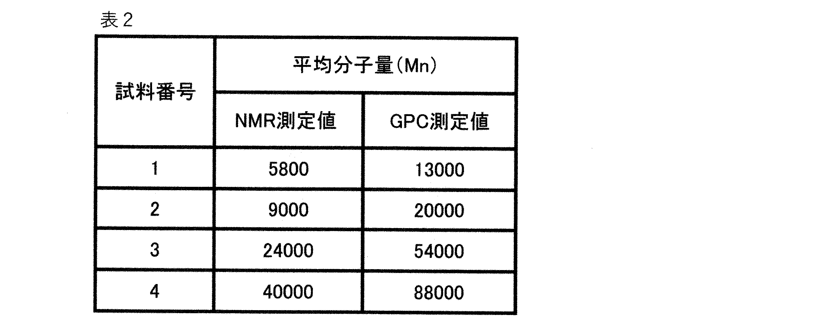
表3および表4の「第1バインダー」の欄に示した片末端エステル化エチルセルロース(数平均分子量=2.0×10⁴)または片末端カルボキシル化エチルセルロース(数平均分子量=2.0×10⁴)を1.1質量部(ニッケル粉末とセラミック粉末との総表面積に対して2.9mg/m2)と、有機溶剤としてのジヒドロターピネオールアセテートを39.7質量部と、を混合して、第1有機ビヒクルを得た。
・片末端エステル化エチルセルロース、
・セルロースアセテートブチレート、
・アクリルバインダーA(ポリメタクリル酸イソブチルからなるバインダー)、
・ポリビニルブチラール系樹脂、
・片末端エステル化エチルセルロースとポリビニルブチラール系樹脂の混合、
・セルロースアセテートブチレートとポリビニルブチラール系樹脂の混合、
・セルロースアセテートブチレートとアクリルバインダーAの混合、
・共重合物A(詳細は後述する。)、
・共重合物B(詳細は後述する。)、
・共重合物C(詳細は後述する。)、
・共重合物D(詳細は後述する。)、
・共重合物E(詳細は後述する。)、および
・共重合物F(詳細は後述する。)、
のいずれかを1.1質量部と、
ジヒドロターピネオールアセテート8.9質量と、
からなる第2有機ビヒクルを添加し、ロール分散処理して、導電性ペーストを完成させた。
共重合物Aは、片末端カルボキシル化エチルセルロースとアクリルバインダーB(主モノマーはメタクリル酸イソブチルとし、メタクリル酸2-ヒドロキシエチルを5mol%含む。)との共重合物である。
共重合物Bは、片末端エステル化エチルセルロースとポリビニルブチラール系樹脂との共重合物である。
共重合物Cは、片末端カルボキシル化エチルセルロースとポリビニルブチラール系樹脂との共重合物である。
共重合物Dは、片末端カルボキシル化エチルセルロースとポリビニルブチラール系樹脂との共重合物である。
共重合物Eは、セルロースアセテートブチレートとポリビニルブチラール系樹脂との共重合物である。
共重合物Fは、セルロースアセテートブチレートとアクリルバインダーB(主モノマーはメタクリル酸イソブチルとし、メタクリル酸2-ヒドロキシエチルを5mol%含む。)との共重合物である。
作製した導電性ペーストについて、以下の操作をして、バインダーの吸着量を評価した。
なお、試料となる導電性ペーストでは、ポリカルボン酸系の分散剤を使用しているため、実質的に不可逆と見なしてよい吸着状態となっており、上澄みには分散剤が含まれないものとして計算した。
比較例1-1および実施例1-1について、バインダーの吸着量および吸着物を評価するため、追加で以下の評価(1)および評価(2)を実施した。
導電性ペースト200ccに対して400ccのアセトンを添加し、プラネタリーミキサーで30分撹拌した後に、遠心分離機(himac製の「CS100FNX」)により、33000rpmの条件で、15分間処理し、ニッケル粉末とセラミック粉末とを沈殿させ、上澄みを分取した。分取した上澄みを乾燥させ、得られた上澄み乾燥固形分(つまり未吸着のバインダー)をTMS化し、NMR測定することで、未吸着バインダーの同定をした。なお、上澄み中に複数種のバインダーが含まれたり、分散剤などが含まれたりする場合は、HPLC(高速液体クロマトグラフ)での分取が必要となった。
評価(1)の遠心分離で沈殿させた固形分に対して、400ccのアセトンを添加し、プライミクス社製ホモミクサー「MARK II」により、12000rpmの条件で、30分間撹拌処理し、粒子表面に吸着しているバインダーの一部を脱吸着させた。
BET径150nmのチタン酸バリウムを主成分とするセラミック材料と、ポリビニルブチラール系樹脂と、トルエンとエキネンが5:5の溶剤と、可塑剤であるトリエチレングリコールジ(2-エチルヘキサノアート)と、を所定の割合で混合し、ビーズミルを用いて湿式分散処理することによって、セラミックスラリーを得た。
上記の未焼成積層体チップから無作為に選択した100個の未焼成積層体チップそれぞれについて、押切りの切断面を光学顕微鏡により観察し、構造欠陥としての導電性塗膜中の凝集破壊(内部電極層内の剥がれ)の有無を確認した。
◎:構造欠陥が観察された積層体の個数が0または1個である。
○:構造欠陥が観察された積層体の個数が2個以上かつ5個以下である。
×:構造欠陥が観察された積層体の個数が6個以上である。

実験例2では、導電性ペースト中の有機ビヒクルの組成を変えた試料について、実験例1の場合と同様の方法で、バインダー吸着量および構造欠陥の発生を評価した。
表5に示した実施例2-1~2-4を得るため、BET径177nm(SSA=3.8m2/g)のニッケル粉末を45.5質量部と、BET径13nm(SSA=77m2/g)のチタン酸バリウムを主成分とするセラミック粉末を3.0質量部と、ポリカルボン酸系高分子分散剤を0.70質量部と、第1バインダーとしての数平均分子量2.0×104の片末端カルボキシル化エチルセルロースを表5の「第1バインダー」の欄に示した質量部と、有機溶剤としてのジヒドロターピネオールアセテートを39.7質量部と、を混合し、ロール分散処理して、中間導電性ペーストを得た。

実験例1の場合と同様の方法で、ニッケル粉末とセラミック粉末の総表面積に対するバインダー吸着量の評価と、未焼成積層体を押切りした際の構造欠陥数の評価を実施した。その結果が表6に示されている。

実験例3では、実験例1の場合と同様の方法で、導電性ペーストに含まれるセルロース誘導体の分子量の異なる試料を作製した。
BET径177nm(SSA=3.8m2/g)のニッケル粉末を45.5質量部と、BET径13nm(SSA=77m2/g)のチタン酸バリウムを主成分とするセラミック粉末を3.0質量部と、ポリカルボン酸系高分子分散剤を0.70質量部と、第1バインダーとしての表7の「第1バインダー」の欄に示した数平均分子量の片末端カルボキシル化エチルセルロースを1.1質量部と、ジヒドロターピネオールアセテートを39.7質量部と、を混合し、ロール分散処理して、中間導電性ペーストを得た。
実験例1の場合と同様の方法で、ニッケル粉末とセラミック粉末の総表面積に対するバインダー吸着量の評価と、未焼成積層体を押切りした際の構造欠陥数の評価を実施した。その結果が表7に示されている。なお、表7には、実験例1において作製した実施例1-10の評価結果も示されている。
実験例4では、実験例1の場合と同様の方法で、ペーストに含まれる無機物粒子種の異なる試料を作製した。
BET径204nm(SSA=3.4m2/g)のデカン酸コートCu粉末を45.5質量部と、BET径13nm(SSA=77m2/g)のチタン酸バリウムを主成分とするセラミック粉末を3.0質量部と、ポリカルボン酸系高分子分散剤を0.35質量部と、第1バインダーとしての数平均分子量2.0×104の片末端カルボキシル化エチルセルロースを0.8質量部と、ジヒドロターピネオールアセテートを40.05質量部と、を混合し、ロール分散処理して、中間導電性ペーストを得た。
BET径149nm(SSA=6.7m2/g)のチタン酸バリウムを主成分とする粉末を33.6質量部と、ポリカルボン酸系高分子分散剤を0.45質量部と、第1バインダーとしての数平均分子量2.0×104の片末端カルボキシル化エチルセルロースを0.4質量部と、ジヒドロターピネオールアセテートを40.05質量部と、を混合し、ロール分散処理して、中間セラミックペーストを得た。
実施例4-1に係る導電性ペーストについては、実験例1の場合と同様の方法で、未焼成積層体チップを得た。
実施例4-1については、実施例1と同様の方法で、ニッケル粉末とセラミック粉末の総表面積に対するバインダー吸着量の評価と、未焼成積層体を押切りした際の構造欠陥数の評価を実施した。

2 くし型高分子分散剤
3 低分子分散剤
4 第2バインダー
5 第1バインダー
Claims (12)
- 無機物粒子と分散剤とバインダーと有機溶剤とを含み、
前記バインダーは、前記無機物粒子の表面に吸着している第1バインダーと、前記無機物粒子の表面に吸着していない第2バインダーと、を含み、
少なくとも前記第1バインダーが、片末端カルボキシル基または片末端カルボン酸塩を有するセルロース誘導体である、
電子部品用ペースト。 - 前記第2バインダーが、片末端カルボキシル基または片末端カルボン酸塩を有するセルロース誘導体である、請求項1に記載の電子部品用ペースト。
- 前記第2バインダーが、片末端カルボキシル基または片末端カルボン酸塩を有しないセルロース誘導体である、請求項1に記載の電子部品用ペースト。
- 前記第2バインダーが、セルロース誘導体部を有する共重合体またはセルロース誘導体を含む複数高分子混合物である、請求項1に記載の電子部品用ペースト。
- 前記第1バインダーとしての前記片末端カルボキシル基または片末端カルボン酸塩を有するセルロース誘導体は、前記無機物粒子の総表面積に対して、1.0mg/m2以上かつ5.0mg/m2以下含む、請求項1ないし4のいずれかに記載の電子部品用ペースト。
- 前記無機物粒子は、セラミック粒子および金属粒子の少なくとも一方を含む、請求項1ないし5のいずれかに記載の電子部品用ペースト。
- 前記セラミック粒子は、Ba、Ti、Ca、ZrおよびSrから選ばれる少なくとも1つの元素を含む、請求項6に記載の電子部品用ペースト。
- 前記金属粒子は、Cu、Ni、AuおよびAgから選ばれる少なくとも1つの金属を含む、請求項6に記載の電子部品用ペースト。
- 前記片末端カルボキシル基または片末端カルボン酸塩を有するセルロース誘導体は、片末端カルボキシル基または片末端カルボン酸塩を有するセルロースエーテルである、請求項1ないし8のいずれかに記載の電子部品用ペースト。
- 前記片末端カルボキシル基または片末端カルボン酸塩を有するセルロースエーテルは、メチルセルロース、エチルセルロース、ヒドロキシエチルセルロース、ヒドロキシプロピルセルロース、エチルヒドロキシエチルセルロースおよびヒドロキシプロピルメチルセルロースから選ばれる少なくとも1種である、請求項9に記載の電子部品用ペースト。
- 前記分散剤は高分子分散剤である、請求項1ないし10のいずれかに記載の電子部品用ペースト。
- 前記高分子分散剤はポリカルボン酸系分散剤である、請求項11に記載の電子部品用ペースト。
Priority Applications (4)
| Application Number | Priority Date | Filing Date | Title |
|---|---|---|---|
| CN202280070299.0A CN118120032A (zh) | 2021-12-01 | 2022-10-15 | 电子部件用糊剂 |
| JP2023564783A JP7652287B2 (ja) | 2021-12-01 | 2022-10-15 | 電子部品用ペースト |
| KR1020247018117A KR102934404B1 (ko) | 2021-12-01 | 2022-10-15 | 전자부품용 페이스트 |
| TW111145894A TW202336121A (zh) | 2021-12-01 | 2022-11-30 | 電子零件用膏 |
Applications Claiming Priority (2)
| Application Number | Priority Date | Filing Date | Title |
|---|---|---|---|
| JP2021-195053 | 2021-12-01 | ||
| JP2021195053 | 2021-12-01 |
Publications (1)
| Publication Number | Publication Date |
|---|---|
| WO2023100503A1 true WO2023100503A1 (ja) | 2023-06-08 |
Family
ID=86611987
Family Applications (1)
| Application Number | Title | Priority Date | Filing Date |
|---|---|---|---|
| PCT/JP2022/038492 Ceased WO2023100503A1 (ja) | 2021-12-01 | 2022-10-15 | 電子部品用ペースト |
Country Status (5)
| Country | Link |
|---|---|
| JP (1) | JP7652287B2 (ja) |
| KR (1) | KR102934404B1 (ja) |
| CN (1) | CN118120032A (ja) |
| TW (1) | TW202336121A (ja) |
| WO (1) | WO2023100503A1 (ja) |
Citations (2)
| Publication number | Priority date | Publication date | Assignee | Title |
|---|---|---|---|---|
| JP2018131681A (ja) * | 2017-02-14 | 2018-08-23 | 住友金属鉱山株式会社 | ニッケルペースト及びその製造方法、並びにニッケル有機スラリー及びその製造方法 |
| JP2021051916A (ja) * | 2019-09-25 | 2021-04-01 | 株式会社ノリタケカンパニーリミテド | 導電性ペーストとこれを用いた電子部品の製造方法 |
Family Cites Families (3)
| Publication number | Priority date | Publication date | Assignee | Title |
|---|---|---|---|---|
| JP4881193B2 (ja) | 2007-03-09 | 2012-02-22 | 三菱樹脂株式会社 | 導電性ペースト組成物 |
| JP6795362B2 (ja) | 2016-09-15 | 2020-12-02 | イー・アイ・デュポン・ドウ・ヌムール・アンド・カンパニーE.I.Du Pont De Nemours And Company | 接合用の導電性ペースト |
| JP6939015B2 (ja) | 2017-03-29 | 2021-09-22 | 住友金属鉱山株式会社 | 積層セラミックコンデンサ内部電極用のグラビア印刷用導電性ペースト |
-
2022
- 2022-10-15 CN CN202280070299.0A patent/CN118120032A/zh active Pending
- 2022-10-15 WO PCT/JP2022/038492 patent/WO2023100503A1/ja not_active Ceased
- 2022-10-15 KR KR1020247018117A patent/KR102934404B1/ko active Active
- 2022-10-15 JP JP2023564783A patent/JP7652287B2/ja active Active
- 2022-11-30 TW TW111145894A patent/TW202336121A/zh unknown
Patent Citations (2)
| Publication number | Priority date | Publication date | Assignee | Title |
|---|---|---|---|---|
| JP2018131681A (ja) * | 2017-02-14 | 2018-08-23 | 住友金属鉱山株式会社 | ニッケルペースト及びその製造方法、並びにニッケル有機スラリー及びその製造方法 |
| JP2021051916A (ja) * | 2019-09-25 | 2021-04-01 | 株式会社ノリタケカンパニーリミテド | 導電性ペーストとこれを用いた電子部品の製造方法 |
Also Published As
| Publication number | Publication date |
|---|---|
| CN118120032A (zh) | 2024-05-31 |
| KR20240100390A (ko) | 2024-07-01 |
| KR102934404B1 (ko) | 2026-03-06 |
| JP7652287B2 (ja) | 2025-03-27 |
| TW202336121A (zh) | 2023-09-16 |
| JPWO2023100503A1 (ja) | 2023-06-08 |
Similar Documents
| Publication | Publication Date | Title |
|---|---|---|
| KR101829788B1 (ko) | 폴리비닐 아세탈 수지, 그 슬러리 조성물, 세라믹 그린 시트 및 적층 세라믹 콘덴서 | |
| TWI658109B (zh) | 黏著劑樹脂之製造方法及樹脂組成物之製造方法以及黏著劑樹脂及樹脂組成物 | |
| CN104620325B (zh) | 导电性糊膏、及层叠陶瓷电子零件与其制造方法 | |
| KR102937110B1 (ko) | 전자부품용 페이스트 | |
| TWI637994B (zh) | 陶瓷成形用或導電糊用黏合劑、及彼等之用途、以及陶瓷胚片及塗敷片、及彼等之製造方法 | |
| JP5965808B2 (ja) | ペースト及び積層セラミックコンデンサ | |
| KR20060103815A (ko) | 도공 페이스트용 결합제 수지 | |
| JP7061795B2 (ja) | 高分子化合物及びそれを含む高分子組成物、並びに無機粒子含有組成物 | |
| CN113227018B (zh) | 陶瓷浆料组合物和生产叠层陶瓷部件的方法 | |
| US10392535B2 (en) | Binder resin for inorganic particle-dispersed pastes and inorganic particle-dispersed paste | |
| JP2008285589A (ja) | 樹脂組成物、導電ペースト及びセラミックペースト | |
| JP6542476B2 (ja) | 共重合体及びその製造方法、並びに共重合体組成物 | |
| JP5767923B2 (ja) | 導電ペースト | |
| WO2023100503A1 (ja) | 電子部品用ペースト | |
| JP5824388B2 (ja) | 導電ペースト | |
| KR20250025493A (ko) | 도전성 페이스트, 전자 부품 및 적층 세라믹 콘덴서 | |
| JP7457487B2 (ja) | 導電ペースト | |
| JP5528156B2 (ja) | セラミックグリーンシートおよびその製造方法 | |
| JP6742791B2 (ja) | 焼成ペースト組成物、及び共重合体の製造方法 | |
| JP2013073689A (ja) | 導電ペースト | |
| WO2022265080A1 (ja) | 樹脂、及び樹脂組成物 | |
| JP2025107821A (ja) | 導電性ペースト、電子部品及び積層セラミックコンデンサ | |
| JP7692543B1 (ja) | グラビア印刷用Niペースト、ならびに電子部品の製造方法 | |
| TW202600492A (zh) | 展色劑、導電性膏、電子零件及積層陶瓷電容 | |
| TW202604985A (zh) | 聚乙烯縮醛樹脂 |
Legal Events
| Date | Code | Title | Description |
|---|---|---|---|
| 121 | Ep: the epo has been informed by wipo that ep was designated in this application |
Ref document number: 22900937 Country of ref document: EP Kind code of ref document: A1 |
|
| WWE | Wipo information: entry into national phase |
Ref document number: 2023564783 Country of ref document: JP |
|
| WWE | Wipo information: entry into national phase |
Ref document number: 202280070299.0 Country of ref document: CN |
|
| NENP | Non-entry into the national phase |
Ref country code: DE |
|
| 122 | Ep: pct application non-entry in european phase |
Ref document number: 22900937 Country of ref document: EP Kind code of ref document: A1 |