WO2023100439A1 - 樹脂封止装置及び樹脂封止方法 - Google Patents
樹脂封止装置及び樹脂封止方法 Download PDFInfo
- Publication number
- WO2023100439A1 WO2023100439A1 PCT/JP2022/034308 JP2022034308W WO2023100439A1 WO 2023100439 A1 WO2023100439 A1 WO 2023100439A1 JP 2022034308 W JP2022034308 W JP 2022034308W WO 2023100439 A1 WO2023100439 A1 WO 2023100439A1
- Authority
- WO
- WIPO (PCT)
- Prior art keywords
- resin
- work
- unit
- supply
- identification mark
- Prior art date
Links
- 229920005989 resin Polymers 0.000 title claims abstract description 465
- 239000011347 resin Substances 0.000 title claims abstract description 465
- 238000000034 method Methods 0.000 title claims description 26
- 239000000463 material Substances 0.000 claims abstract description 26
- 238000005259 measurement Methods 0.000 claims abstract description 23
- 238000007789 sealing Methods 0.000 claims description 101
- 238000000465 moulding Methods 0.000 claims description 76
- 238000003860 storage Methods 0.000 claims description 42
- 239000000758 substrate Substances 0.000 claims description 14
- 230000032258 transport Effects 0.000 claims description 12
- 230000008569 process Effects 0.000 claims description 9
- 238000003384 imaging method Methods 0.000 claims description 6
- 238000005538 encapsulation Methods 0.000 claims description 4
- 238000004891 communication Methods 0.000 description 16
- 238000004519 manufacturing process Methods 0.000 description 16
- 238000004364 calculation method Methods 0.000 description 11
- 238000011027 product recovery Methods 0.000 description 11
- 238000000605 extraction Methods 0.000 description 10
- 238000012546 transfer Methods 0.000 description 10
- 230000002950 deficient Effects 0.000 description 6
- 230000006870 function Effects 0.000 description 5
- 230000001276 controlling effect Effects 0.000 description 4
- 238000001816 cooling Methods 0.000 description 4
- 238000010586 diagram Methods 0.000 description 4
- 239000007788 liquid Substances 0.000 description 4
- 239000000203 mixture Substances 0.000 description 4
- -1 polytetrafluoroethylene Polymers 0.000 description 4
- 238000005303 weighing Methods 0.000 description 4
- 238000012937 correction Methods 0.000 description 3
- 239000000284 extract Substances 0.000 description 3
- 238000007689 inspection Methods 0.000 description 3
- 230000007246 mechanism Effects 0.000 description 3
- 239000004065 semiconductor Substances 0.000 description 3
- 239000004743 Polypropylene Substances 0.000 description 2
- 238000000748 compression moulding Methods 0.000 description 2
- 230000007423 decrease Effects 0.000 description 2
- 238000010438 heat treatment Methods 0.000 description 2
- 230000000704 physical effect Effects 0.000 description 2
- 229920000139 polyethylene terephthalate Polymers 0.000 description 2
- 239000005020 polyethylene terephthalate Substances 0.000 description 2
- 229920001343 polytetrafluoroethylene Polymers 0.000 description 2
- 239000004810 polytetrafluoroethylene Substances 0.000 description 2
- 238000012545 processing Methods 0.000 description 2
- 230000001105 regulatory effect Effects 0.000 description 2
- 238000001721 transfer moulding Methods 0.000 description 2
- 238000011179 visual inspection Methods 0.000 description 2
- VEXZGXHMUGYJMC-UHFFFAOYSA-M Chloride anion Chemical compound [Cl-] VEXZGXHMUGYJMC-UHFFFAOYSA-M 0.000 description 1
- 229920001328 Polyvinylidene chloride Polymers 0.000 description 1
- 239000000853 adhesive Substances 0.000 description 1
- 230000001070 adhesive effect Effects 0.000 description 1
- 230000008859 change Effects 0.000 description 1
- 230000006835 compression Effects 0.000 description 1
- 238000007906 compression Methods 0.000 description 1
- 238000011109 contamination Methods 0.000 description 1
- 229920001577 copolymer Polymers 0.000 description 1
- 230000007547 defect Effects 0.000 description 1
- 238000013461 design Methods 0.000 description 1
- 239000006185 dispersion Substances 0.000 description 1
- 229920000840 ethylene tetrafluoroethylene copolymer Polymers 0.000 description 1
- 239000004744 fabric Substances 0.000 description 1
- 239000011521 glass Substances 0.000 description 1
- 230000005484 gravity Effects 0.000 description 1
- 238000010191 image analysis Methods 0.000 description 1
- 230000006872 improvement Effects 0.000 description 1
- 230000007257 malfunction Effects 0.000 description 1
- 239000002861 polymer material Substances 0.000 description 1
- 229920001155 polypropylene Polymers 0.000 description 1
- 239000005033 polyvinylidene chloride Substances 0.000 description 1
- 239000000843 powder Substances 0.000 description 1
- 238000002360 preparation method Methods 0.000 description 1
- 238000011084 recovery Methods 0.000 description 1
- 230000009467 reduction Effects 0.000 description 1
- 239000003826 tablet Substances 0.000 description 1
- 229920001187 thermosetting polymer Polymers 0.000 description 1
- 238000004804 winding Methods 0.000 description 1
Images


Classifications
-
- B—PERFORMING OPERATIONS; TRANSPORTING
- B29—WORKING OF PLASTICS; WORKING OF SUBSTANCES IN A PLASTIC STATE IN GENERAL
- B29C—SHAPING OR JOINING OF PLASTICS; SHAPING OF MATERIAL IN A PLASTIC STATE, NOT OTHERWISE PROVIDED FOR; AFTER-TREATMENT OF THE SHAPED PRODUCTS, e.g. REPAIRING
- B29C43/00—Compression moulding, i.e. applying external pressure to flow the moulding material; Apparatus therefor
- B29C43/02—Compression moulding, i.e. applying external pressure to flow the moulding material; Apparatus therefor of articles of definite length, i.e. discrete articles
- B29C43/18—Compression moulding, i.e. applying external pressure to flow the moulding material; Apparatus therefor of articles of definite length, i.e. discrete articles incorporating preformed parts or layers, e.g. compression moulding around inserts or for coating articles
-
- B—PERFORMING OPERATIONS; TRANSPORTING
- B29—WORKING OF PLASTICS; WORKING OF SUBSTANCES IN A PLASTIC STATE IN GENERAL
- B29C—SHAPING OR JOINING OF PLASTICS; SHAPING OF MATERIAL IN A PLASTIC STATE, NOT OTHERWISE PROVIDED FOR; AFTER-TREATMENT OF THE SHAPED PRODUCTS, e.g. REPAIRING
- B29C43/00—Compression moulding, i.e. applying external pressure to flow the moulding material; Apparatus therefor
- B29C43/32—Component parts, details or accessories; Auxiliary operations
- B29C43/34—Feeding the material to the mould or the compression means
-
- H—ELECTRICITY
- H01—ELECTRIC ELEMENTS
- H01L—SEMICONDUCTOR DEVICES NOT COVERED BY CLASS H10
- H01L21/00—Processes or apparatus adapted for the manufacture or treatment of semiconductor or solid state devices or of parts thereof
- H01L21/02—Manufacture or treatment of semiconductor devices or of parts thereof
- H01L21/04—Manufacture or treatment of semiconductor devices or of parts thereof the devices having potential barriers, e.g. a PN junction, depletion layer or carrier concentration layer
- H01L21/50—Assembly of semiconductor devices using processes or apparatus not provided for in a single one of the subgroups H01L21/06 - H01L21/326, e.g. sealing of a cap to a base of a container
- H01L21/56—Encapsulations, e.g. encapsulation layers, coatings
Definitions
- the present invention relates to a resin sealing device and a resin sealing method.
- the amount of resin supplied may be adjusted based on the state of mounting the electronic parts in order to reduce the deviation in the thickness of the molded resin.
- Patent Document 1 discloses a resin molding apparatus that processes a workpiece into a molded product by resin-molding a workpiece using a resin-sealed mold that includes an upper mold and a lower mold.
- a resin molding apparatus is disclosed that calculates the volume of an electronic component based on the thickness of a workpiece measured using a measuring instrument, and adjusts the supply amount of molding resin.
- the present invention has been made in view of such circumstances, and an object of the present invention is to provide a resin sealing apparatus and a resin sealing method capable of improving manufacturing efficiency.
- a resin sealing apparatus is a resin sealing apparatus for resin-sealing an electronic component of a work including a substrate and an electronic component, and includes a work supply unit that supplies the work, and a resin that supplies the work. It comprises a resin supply unit and a resin molding unit that molds resin onto a workpiece.
- the workpiece supply unit has a reading unit that reads an identification mark for identifying the workpiece. It is associated with resin supply data based on actual measurements indicating the mounting status of parts, and the resin supply unit dispenses a predetermined amount of resin for each workpiece based on the resin supply data associated with the identification mark read by the reading unit. supply.
- the amount of resin to be supplied can be determined by reading the identification mark associated with the resin supply data in the resin sealing apparatus. Therefore, the time required from the supply of the work to the molding of the resin can be shortened, and the manufacturing efficiency can be improved.
- the work supply unit is set with a work container for storing a plurality of works, and the work container contains the work for which the actual measurement value indicating the mounting state of the electronic component on the base material is measured. good too.
- the identification mark is attached to the work
- the reading unit may read the identification mark attached to the work delivered from the work container.
- the identification mark is attached to the work container, and the reading unit may read the identification mark attached to the work container.
- the above aspect further includes a work loader that transports the work and a resin loader that transports the resin, and the resin supply unit supplies a predetermined amount of resin corresponding to the work to the resin loader before the work is placed on the work loader. You may start the process to
- the resin sealing device is communicably connected to a measuring device that measures an actual measurement value indicating the mounting status of the electronic component on the substrate, and the resin sealing device receives the resin supply data associated with the identification mark. , may be obtained from the measurement device.
- the measuring device may calculate resin supply data based on three-dimensional images formed by imaging the workpiece from three or more directions.
- the resin supply data may be a volume value indicating the total volume of electronic components on the substrate.
- the resin supply data may be the amount of resin supplied calculated based on the volume value indicating the total volume of the electronic component on the substrate.
- a resin-sealing method is a resin-sealing method using a resin-sealing device for resin-sealing an electronic component of a work including a substrate and an electronic component
- the resin-sealing device includes a work supply unit that supplies a work, a resin supply unit that supplies resin, and a resin molding unit that molds the resin onto the work, and the work supply unit reads an identification mark for identifying the work. It has a reading unit, and the resin sealing method is to read an identification mark for identifying the work by the reading unit, and the identification mark is based on actual measurement values indicating the mounting status of electronic components on the base material. Reading an identification mark associated with resin supply data, and supplying a predetermined amount of resin for each work by a resin supply unit based on the resin supply data associated with the identification mark read by the reading unit. and including.
- the amount of resin to be supplied can be determined by reading the identification mark associated with the resin supply data in the resin sealing apparatus. Therefore, the time required from the supply of the work to the molding of the resin can be shortened, and the manufacturing efficiency can be improved.
- the above aspect further includes placing the workpiece on the work loader and transporting it, and placing the resin on the resin loader and transporting it, and supplying the resin by the resin supply unit includes placing the work on the work loader. , the process of supplying a predetermined amount of resin corresponding to the workpiece to the resin loader may be started.
- preparing the workpiece by mounting the electronic component on the base material, capturing the workpiece from three or more directions to obtain a three-dimensional image, and determining the appearance of the workpiece based on the three-dimensional image. It may further include inspecting and calculating resin supply data based on the three-dimensional image.
- FIG. 1 is a plan view schematically showing the configuration of a resin sealing device according to one embodiment.
- FIG. 2 is a block diagram schematically showing the configuration of a control unit according to one embodiment.
- Fig. 1 shows the layout when viewed from above.
- the front, rear, left, and right directions are given for convenience in order to help understand the positional relationship of each member.
- the resin sealing apparatus 1 is a manufacturing apparatus for manufacturing a molded product M by resin-sealing an electronic component P of a work W including a substrate S and an electronic component P.
- the resin sealing apparatus 1 fixes the functional member H together with the resin R when the electronic component P is resin-sealed.
- the functional member H is provided, for example, so as to be exposed on the side of the molded article M opposite to the side on which the substrate S is exposed.
- the substrate S is, for example, an interposer substrate, but is not limited to this, and may be a lead frame, a carrier plate with an adhesive sheet, a semiconductor substrate, or the like.
- the electronic component P is, for example, a semiconductor element such as an IC chip, but is not limited to this, and may be various active elements, passive elements, MEMS devices, or the like.
- the resin R is, for example, a granular thermosetting resin, but is not limited thereto, and the form of the resin may be powder, liquid, tablet, sheet, or the like.
- the functional member H is, for example, a heat radiating member that releases heat generated by the electronic component P, but is not limited to this, and may be a shielding member that shields electromagnetic waves.
- the resin sealing apparatus 1 includes a workpiece supply unit 10, a resin supply unit 40, a functional member supply unit 50, resin molding units 20 and 30, a molded product recovery unit 90, and a first A loader 60 and a second loader 70 are provided.
- the work supply unit 10, the resin supply unit 40, the resin molding units 20 and 30, and the molded product recovery unit 90 are arranged side by side in the left-right direction.
- the resin supply unit 40 and the functional member supply unit 50 are arranged side by side in the front-rear direction.
- the work supply unit 10 supplies the work W.
- the work supply unit 10 includes a work storage section 11 , a work transfer section 13 , a work preheating section 15 and a work supply control panel 19 . As shown in FIG. 1, the work supply unit 10 is arranged, for example, at the left end of the resin sealing device 1 when viewed from above.
- the work storage unit 11 stores a plurality of works W and sequentially delivers the works W.
- the work storage unit 11 is provided with a plurality of work magazines WM in which a plurality of works W are stored so as to overlap each other, and a work elevation that adjusts the positions of the work magazines WM and sends out the work W. It is The empty work magazine WM is removed from the work elevation, and the work magazine WM containing a plurality of works W is attached to the work elevation.
- the work magazine WM corresponds to an example of the "work container" according to the present invention.
- the work delivery section 13 delivers the work W received from the work storage section 11 to the work preheating section 15 .
- the work delivery unit 13 includes a work index for receiving and aligning the works W sent out from the work storage unit 11 and a work pick and place for delivering the works W aligned by the work index to the work preheating unit 15. ing.
- the work preheating section 15 preheats the work W received from the work delivery section 13 and delivers it to the first loader 60 .
- the work preheating section 15 is provided with a preheat rail for heating the work W received from the work storage section 11 .
- the heating method in the work preheating section 15 is not limited to the above, and the work preheating section 15 may be provided with, for example, a hot plate, a hot air heater, an infrared heater, or the like.
- the work preheating section may be omitted. That is, the resin sealing apparatus may be configured to carry the work into the mold without preheating the work.
- the work supply control panel 19 is a control panel for controlling the operation of the work supply unit 10. When viewed from above as shown in FIG. 1, the work supply control panel 19 is arranged in front of the work supply unit 10 .
- the work supply control panel 19 includes a display section for displaying control parameters of the work supply unit 10 and an input section for inputting the control parameters of the work supply unit 10 .
- the molded article recovery unit 90 recovers the molded article M.
- the molded article collection unit 90 includes a molded article receiving section 91 , a molded article delivery section 93 , and a molded article storage section 95 . As shown in FIG. 1, the molded product recovery unit 90 is arranged, for example, at the right end of the resin sealing device 1 when viewed from above.
- the molded product receiving unit 91 delivers the molded product M received from the first loader 60 to the molded product delivery unit 93 .
- the molded article receiving section 91 is equipped with a cooling pallet for cooling the molded article M. As shown in FIG.
- the molded product receiving part 91 does not need to be equipped with a cooling pallet.
- the molded product delivery unit 93 delivers the molded product M received from the molded product receiving unit 91 to the molded product storage unit 95 .
- the molded product delivery unit 93 includes a molded product index for receiving and aligning the molded product M delivered by the molded product receiving unit 91 and a molding unit for delivering the aligned molded product M to the molded product storage unit 95 . Goods are picked and placed.
- the molded product storage unit 95 receives and stores the molded product M.
- the molded product storage unit 95 may include a plurality of molded product magazines each storing a plurality of molded products M so as to overlap each other, and a molded product elevator for receiving the molded products M by adjusting the positions of the plurality of molded product magazines. are provided.
- the molded product recovery unit 90 includes a volume measuring unit for measuring the volume of the molded product M, a weight measuring unit for measuring the weight of the workpiece W, a thickness measuring unit for measuring the thickness of the workpiece W, and an external appearance of the molded product M.
- a visual inspection unit or the like for inspecting may be further provided.
- the resin sealing apparatus according to one embodiment of the present invention is a transfer-type resin sealing apparatus
- the molded product recovery unit separates unnecessary resin called cull, spool, runner, gate, etc. from the molded product M.
- a degating section and a scrap box or the like for collecting the separated unnecessary resin may be provided.
- the resin molding unit 20 molds the resin R on the workpiece W and the functional member H.
- the resin molding unit 20 includes a mold 21 , a film handler 27 and a resin molding control panel 29 . As shown in FIG. 1, the resin molding unit 20 is connected to, for example, the right side of the work supply unit 10 when viewed from above.
- the mold 21 is a resin-sealing mold that heats and cures the resin R in its internal cavity to seal the electronic component P.
- the mold 21 has a pair of openable and closable lower and upper molds.
- the film handler 27 supplies the film F to the mold 21.
- the film F is a release film that prevents the resin R from entering the gap of the cavity and facilitates peeling of the molded article M.
- the film handler 27 includes an unwinding section for supplying unused film F provided in a roll and a winding section for collecting used film F. As shown in FIG.
- polymer materials having excellent heat resistance, peelability, flexibility, and extensibility such as PTFE (polytetrafluoroethylene), ETFE (polytetrafluoroethylene-ethylene copolymer), FEP ( tetrafluoroethylene-hexafluoropropylene copolymer), PET (polyethylene terephthalate), PP (polypropylene), PVDC (polyvinylidine chloride), or the like is preferably used.
- the material of the film F is not limited to the above, and may be, for example, fluorine-impregnated glass cloth.
- the thickness of the film F is suitably selected according to the physical properties of the material, and is, for example, about 50 ⁇ m.
- the shape of the film F is not limited to a roll shape, and may be a strip shape.
- the resin molding control panel 29 is a control board for controlling the operation of the resin molding unit 20. As shown in FIG. 1, the resin molding control panel 29 is arranged in front of the resin molding unit 20 when viewed from above. For example, the resin molding control panel 29 includes a display section for displaying control parameters of the resin molding unit 20 and an input section for inputting the control parameters of the resin molding unit 20 .
- the resin molding unit 30 includes a mold 31, a film handler 37, and a resin molding control panel 39. As shown in FIG. 1, the resin molding unit 30 is connected to the left side of the molded product recovery unit 90, for example, when viewed from above. Since the configuration of the resin molding unit 30 is the same as that of the resin molding unit 20, the description of the mold 31, the film handler 37 and the resin molding control panel 39 is omitted.
- At least part of the functions of the resin molding control panels 29 and 39 may be integrated into the work supply control panel 19.
- the control parameters of the resin molding units 20 and 30 may be displayed on the display section of the workpiece supply control panel 19, and the control parameters of the resin molding units 20 and 30 may be input to the input section of the workpiece supply control panel 19. good.
- the resin molding control panels 29 and 39 may be omitted.
- the resin supply unit 40 supplies the resin R to the second loader 70. As shown in FIG. 1, the resin supply unit 40 is connected to the right side of the resin molding unit 20 and is connected to the left side of the resin molding unit 30 when viewed from above.
- the resin supply unit 40 includes a resin supply section 41 .
- the resin supply unit 41 includes, for example, a hopper 42, a feeder 43, and a flow control valve 45.
- the hopper 42 corresponds to an example of a storage section that stores the resin R.
- the feeder 43 corresponds to an example of a delivery unit that delivers the resin R received from the hopper 42 to a second loader hand 71, which will be described later.
- the flow rate adjustment valve 45 corresponds to an example of an adjustment section that adjusts the supply speed and supply amount of the resin R from the hopper 42 to the feeder 43 .
- the resin supply unit may include a syringe that stores the resin, a piston that pushes out the resin, a servomotor that drives the piston, and a pinch valve that opens and closes the tip of the syringe.
- the adjustment unit corresponds to a servomotor and a pinch valve.
- the resin supply unit 40 includes a weight measuring unit for measuring the weight of the resin R, a resin preheating unit for preheating the resin R, a resin guard used as a frame surrounding the resin R, and a vibrating unit for dispersing the resin R by vibration. , and an inspection unit or the like for inspecting the degree of dispersion of the resin R may be further provided.
- the functional material supply unit 50 supplies the functional material H to the second loader 70 .
- the functional member supply unit 50 includes a functional member storage section 51 and a functional member delivery section 53 .
- the functional member supply unit 50 is connected to the front side of the resin supply unit 40 .
- the functional member supply unit 50 is arranged on the front side of the resin sealing device 1 .
- the front side of the resin sealing apparatus 1 is the side on which the work supply control panel 19 and the resin molding control panels 29 and 39 are arranged in the front-rear direction.
- the functional member supply unit 50 is arranged on the opposite side of the resin supply unit 41 in the front-rear direction as viewed from the first guide unit 60R, which will be described later.
- the functional member supply unit 50 is positioned in front of the first guide portion 60R, and the resin supply portion 41 is positioned behind the first guide portion 60R.
- the first guide portion 60R is provided between the functional member supply unit 50 and the resin supply portion 41.
- the functional member storage unit 51 stores a plurality of functional members H and delivers the functional members H sequentially.
- the functional member storage section 51 may include a plurality of functional member magazines in which a plurality of functional members H are stored so as to overlap each other, and a functional member elevator that adjusts the positions of the plurality of functional member magazines and feeds out the functional members H. are provided.
- the functional member magazine is, for example, a so-called slit magazine in which a plurality of functional members H are held in slits at intervals.
- the functional member magazine is not limited to the above, and may be a so-called stack magazine in which a plurality of functional members H are directly stacked and held.
- the functional member delivery section 53 delivers the functional member H received from the functional member storage section 51 to the second loader 70 .
- the functional member delivery unit 53 has a functional member index for receiving and aligning the functional members H delivered from the functional member storage unit 51, and a functional member pick-and-place for delivering the functional members H aligned by the functional member index. are provided.
- the functional member supply unit 50 includes a volume measuring section for measuring the volume of the functional member H, a weight measuring section for measuring the weight of the functional member H, a thickness measuring section for measuring the thickness of the functional member H, and an appearance of the functional member H. and a functional member preheating section for preheating the functional member H may be further provided.
- the first loader 60 conveys the work W from the work supply unit 10 to the resin molding units 20 and 30.
- the first loader 60 corresponds to an example of a "work loader” according to the present invention.
- the first loader 60 is configured to be movable in the left-right direction along the first guide portion 60R.
- the first guide portion 60R extends in the left-right direction across the work supply unit 10, the resin molding units 20 and 30, the resin supply unit 40, and the molded product recovery unit 90.
- the first guide portion 60 ⁇ /b>R corresponds to an example of the transport path of the first loader 60 .
- the first guide portion 60R is provided behind the molds 21 and 31 and in front of the resin supply portion 41, for example.
- the first loader 60 not only transports the workpiece W, but also transports the molded product M from the resin molding units 20 and 30 to the molded product recovery unit 90 . That is, the first loader 60 corresponds to an example of a molded article unloader.
- the resin encapsulation apparatus may further include a molded product unloader configured to be movable in the left-right direction along the first guide portion 60R.
- the resin sealing device may further include a guide section for moving the molded article unloader apart from the first guide section 60R.
- the first loader 60 has a first loader hand 61 having a mechanism for holding the workpiece W and the molded product M.
- the first loader hand 61 is configured to move back and forth with respect to the mold 21 .
- the first loader hand 61 receives the work W from the work preheating section 15 or the work transfer section 13 in the work supply unit 10, moves in the left-right direction to the resin molding unit 20, and stops behind the mold 21. do.
- the first loader hand 61 enters the mold 21 from behind and loads the workpiece W into the mold 21 .
- the first loader hand 61 that has handed over the workpiece W to the mold 21 retreats behind the mold 21 .
- the first loader hand 61 which has carried out the molded product M from the mold 21 by the same operation as when carrying in the work W, moves in the left-right direction to the molded product recovery unit 90, and moves to the molded product receiving part 91 or the molded product delivery part 93. deliver the molded product M to
- the second loader 70 transports the resin R received from the resin supply section 41 and the functional member H received from the functional member delivery section 53 .
- the second loader 70 corresponds to an example of a "resin loader" according to the present invention.
- the second loader 70 is configured to be movable in the front-rear direction along the second guide portion 70R.
- the second guide portion 70R is provided, for example, in the resin supply unit 40 and extends in the front-rear direction.
- the second guide portion 70 ⁇ /b>R corresponds to an example of the conveying route of the second loader 70 . When viewed from above as shown in FIG. 1, the second guide portion 70R intersects the first guide portion 60R, for example.
- the second loader 70 transports both the resin R and the functional member H at the same time, it is not limited to this. One of the resin R and the functional member H may be transported before the other.
- the second loader 70 includes a second loader hand 71 having a holding mechanism for holding the resin R and the functional member H.
- the second loader hand 71 is configured to be rotatable, and configured to move forward and backward with respect to the mold 21 in the horizontal direction.
- the second loader hand 71 moves to a position P1 in front of the first guide part 60R after receiving the resin R at the resin supply part 41.
- the second loader hand 71 turns and moves to the position P2 behind the functional member transfer section 53 .
- the second loader hand 71 moves to the functional member transfer section 53 to receive the functional member H, and then returns to the position P2.
- the second loader hand 71 turns and moves to the right position P3 of the mold 21 .
- the second loader hand 71 enters the mold 21 from the right side and loads the resin R and the functional member H into the mold 21 . After transferring the resin R and the functional member H to the mold 21 , the second loader hand 71 withdraws to the right of the mold 21 .
- the second loader hand 71 receives the functional member H after receiving the resin R, for example, and carries both of them into the mold 21 at the same time, it is not limited to this.
- the second loader hand 71 may receive the resin R after receiving the functional member H.
- the second loader hand 71 may load one of the resin R and the functional member H into the mold 21 and then withdraw from the mold 21 once, and then load the other into the mold 21 .
- the first loader 60 and the second loader 70 operate in the same manner as for the mold 21 of the resin molding unit 20. Therefore, description of the operation of the first loader 60 and the second loader 70 with respect to the mold 31 is omitted. However, the operation of the second loader 70 with respect to the mold 31 is a horizontally reversed operation of the operation of the second loader 70 with respect to the mold 21 .
- FIG. 2 is a block diagram schematically showing the configuration of a control unit according to one embodiment.
- the resin sealing device 1 has a control section 100 .
- the control unit 100 controls the supply amount of the resin R via the flow rate adjustment valve 45 of the resin supply unit 41 .
- the control unit 100 is communicably connected to a measuring device 200 provided outside the resin sealing apparatus 1 .
- Communication between the control unit 100 and the measurement device 200 is, for example, communication by direct wired connection, but is not limited to this.
- Communication between the control unit 100 and the measurement device 200 may be communication by wireless connection, or may be indirect communication via a host computer.
- SECS SEMI EQUIPMENT COMMUNICATION STANDARDS
- GEM GEM
- the control unit 100 includes an acquisition unit 110 , a storage unit 120 , a reading unit 130 , an extraction unit 140 and a calculation unit 150 .
- the acquisition unit 110 acquires resin supply data based on actual measurement values indicating the mounting status of the electronic component P on the base material S through communication with the measurement device 200 .
- the resin supply data acquired by the acquisition unit 110 from the measuring device 200 is, for example, a volume value indicating the total volume of the electronic components P on the substrate S.
- the resin supply data is acquired by the acquisition unit 110 as a set of data paired with the identification data corresponding to the identification mark attached to the work W on which the resin supply data is based.
- the storage unit 120 stores the resin supply data and identification data registered by the acquisition unit 110 as a set of data. That is, the storage unit 120 stores the resin supply data in a state in which it can be referred to based on the identification mark.
- the storage unit 120 stores data related to the mold such as the shape and capacity of the cavity, data related to the resin R such as the specific gravity, target dimensions and tolerances of the molded product M, and resin supply data to calculate the supply amount of the resin R. and a program for operating the control unit 100 may also be stored.
- the reading unit 130 reads the identification mark attached to the work W delivered from the work magazine WM in the work supply unit 10 .
- the identification mark attached to the work W is associated with resin supply data based on the work W measured by the measuring device 200 before being accommodated in the work magazine WM.
- the extraction unit 140 Based on the identification mark read by the reading unit 130, the extraction unit 140 extracts resin supply data associated with the identification mark from the storage unit 120.
- the calculation unit 150 calculates control data for supplying an appropriate amount of resin R to the workpiece W based on the resin supply data extracted by the extraction unit 140 .
- the control data is, for example, a control parameter for controlling the flow regulating valve 45 of the resin supply section 41 to supply a predetermined amount of resin R to the resin supply section 41 .
- the calculation unit 150 extracts the capacity of the cavities of the molds 21 and 31 and the design value of the thickness of the molded product M from the storage unit 120, and calculates the supply amount of the resin R by taking them into account.
- the measuring device 200 is a volume meter for the electronic component P that is communicably connected to the resin sealing device 1 .
- the measuring device 200 also includes a reading unit for reading the identification mark of the workpiece W, an arithmetic unit for processing the measurement result of the volume meter and calculating resin supply data, a communication module for transmitting the resin supply data, and the like. It has The measuring device 200 is, for example, a visual inspection device that inspects the state of mounting of the electronic components P on the substrate S.
- the measuring device 200 is an appearance inspection device, the measuring device 200 is installed in a production line of works W, for example. In the example shown in FIG. 2, the measuring device 200 forms a three-dimensional image of the work W by imaging the work W from eight directions. As shown in FIG.
- the workpiece W can be viewed from three or more directions.
- An accurate three-dimensional image is acquired by imaging the .
- the measuring device 200 Based on this three-dimensional image, the measuring device 200 performs an appearance inspection of the work W and calculates actual measurement values indicating the mounting status of the electronic components P on the base material S.
- the measured values are, for example, the presence or absence of the electronic components P, dimensions, etc.
- a volume value indicating the total volume of the electronic components P on the substrate S which corresponds to an example of resin supply data, is calculated.
- the measuring device 200 transmits the resin supply data and the identification data corresponding to the identification mark attached to the workpiece W measured for calculating the resin supply data to the control unit 100 .
- FIG. 3 is a diagram illustrating an example of a physical configuration of a control unit
- the control unit 100 includes a CPU (Central Processing Unit) 101, a RAM (Random Access Memory) 102, a ROM (Read Only Memory) 103, a communication module 105, a monitor 106, and a keyboard 107. These components are connected to each other via a bus so that data can be sent and received.
- the control unit 100 is configured by, for example, a single computer, but may be realized by combining a plurality of distributed computers.
- the control unit 100 causes the acquisition unit 110, the storage unit 120, the reading unit 130, the extraction unit 140, and the calculation unit 150 to function by executing a predetermined program stored in the RAM 102 or the ROM 103 using the CPU 101. can be done.
- the CPU 101 corresponds to an example of the extraction unit 140 and the calculation unit 150.
- the RAM 102 or ROM 103 corresponds to an example of the storage section 120 .
- Communication module 103 corresponds to an example of acquisition unit 110 .
- the monitor 106 corresponds to an example of a display unit. For example, the monitor 106 displays the resin supply data acquired by the acquisition unit 110, the identification data corresponding to the identification mark read by the reading unit 130, the resin supply data extracted by the extraction unit 140, and the control data calculated by the calculation unit 150. etc. may be displayed.
- the display section of the control section 100 may be shared with at least one display section of the work supply control panel 19 and the resin molding control panels 29 and 39, for example.
- the keyboard 107 corresponds to an example of an input unit.
- Necessary information for the control unit 100 is input to the keyboard 107 .
- the user can input a command such as start, end, or pause of the control unit 100 to the keyboard 107 .
- the input unit may be another device such as a touch panel.
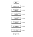
- FIG. 4 is a flow chart schematically showing the first half process of resin sealing.
- FIG. 5 is a flow chart schematically showing the latter half of the resin sealing process.
- the base material S is prepared (S111), and the electronic component P is mounted on the base material S (S112).
- a three-dimensional image of the workpiece W is obtained (S113).
- the measurement device 200 installed in the production line of the work W captures images of the work W from eight directions to obtain a three-dimensional image of the work W.
- the workpiece W is visually inspected (S114). Based on the three-dimensional image of the workpiece W acquired in step S113, the mounting status of the electronic components P, the status of the base material S, and the like are inspected to detect partially defective workpieces W or wholly defective workpieces W.
- the volume of the electronic component P is measured (S115). Based on the three-dimensional image of the electronic component P included in the three-dimensional image of the workpiece W acquired in step S113, the dimensions of the electronic component P are calculated by image analysis. Thereby, the measuring device 200 calculates a volume value indicating the total volume of the electronic component P, which corresponds to the resin supply data.
- the measuring device 200 transmits the resin supply data and the identification data corresponding to the resin supply data to the acquisition unit 110 of the control unit 100 .
- the work W is set in the work magazine WM (S117).
- a workpiece W measured by the measuring device 200 is set in the workpiece magazine WM.
- the step S117 of setting the work W in the work magazine WM may be performed before the step S116 of transmitting the data. For example, after setting the work W in the work magazine WM, only the resin supply data of the work W set in the work magazine WM may be transmitted.
- the acquisition unit 110 receives the resin supply data transmitted by the measuring device 200 and the identification data corresponding to the resin supply data and registers them in the storage unit 120 .
- a database containing a plurality of resin supply data and a plurality of identification data is created in the storage unit 120 .
- the work magazine WM is set in the work storage section 11 (S122).
- Data regarding the work W set in the work magazine WM set in the work storage unit 11 is already stored in the storage unit 120 .
- the identification data corresponding to the identification mark attached to the work W and the resin supply data calculated by measuring the work W are used when the work supply unit 10 is ready to supply the work W. It has already been stored in the storage unit 120 .
- the identification mark of the work W is read (S124).
- the timing of reading the identification mark of the work W is not particularly limited as long as the work W is sent out from the work storage unit 11 .
- the reading unit 130 may read the identification mark from the work W that is being moved from the work storage unit 11 to the work transfer unit 13, or may read the identification mark from the work W set in the work transfer unit 13. . Further, the reading unit 130 may read the identification mark from the work W that is being moved from the work transfer unit 13 to the work preheating unit 15 , or read the identification mark from the work set in the work preheating unit 15 .
- the resin supply data associated with the identification mark is extracted (S125). Based on the identification mark read by the reading unit 130 , the extraction unit 140 extracts resin supply data associated with the identification mark from the storage unit 120 .
- the calculation unit 150 calculates an appropriate supply amount of the resin R based on the resin supply data extracted by the extraction unit 140, and calculates control data for supplying an appropriate supply amount of the resin R to the workpiece W.
- the resin R is supplied to the workpiece W (S127).
- the flow control valve 45 of the resin supply unit 41 is controlled to supply a predetermined amount of resin R optimized for the workpiece W.
- the resin sealing apparatus 1 includes the reading unit 130 for reading the identification mark associated with the resin supply data from the workpiece W, and the workpiece W is detected based on the resin supply data. A predetermined amount of resin R is supplied to . Further, in a resin sealing method according to another aspect of the present invention, the electronic component P is resin-sealed using the resin sealing apparatus 1 .
- the identification mark associated with the resin supply data in advance is used. you should read it.
- the time required to read the identification mark is shorter than the time required to measure the volume of the electronic component P. Therefore, compared to the configuration in which the volume of the electronic component P is measured after the workpiece W is supplied, the time required from the supply of the workpiece W to the molding of the resin R can be shortened, and the manufacturing efficiency can be improved. . In particular, if the volume of the electronic component P is measured more accurately and the supply amount of the resin R is determined more accurately, the time required to measure the volume of the electronic component P becomes longer.
- the time required from the supply of the work W to the molding of the resin R is not affected by the time required to measure the volume of the electronic component P.
- the precision of the supply amount of R can be improved. Therefore, it is possible to reduce the occurrence of defective products and improve manufacturing efficiency.
- the work W supplied in the work supply unit 10 is stored in the work magazine WM after being measured by the measuring device 200, and the reading section 130 reads the identification mark of the work W sent out from the work magazine WM. .
- the identification mark may be attached to the work magazine, and the reading unit may read the identification mark attached to the work magazine.
- an identification mark attached to a work magazine is associated with a plurality of resin supply data for a plurality of works accommodated in the work magazine.
- the amount of resin R to be supplied to each of the plurality of works stored in the work magazine can be calculated. good. Therefore, the time required from the supply of the work W to the molding of the resin R can be further shortened. Moreover, the supply of the resin R can be started before the works W are sent out from the work magazine WM, that is, when the works W are stored in the work magazine WM.
- the resin sealing apparatus 1 separately includes the first loader 60 that transports the work W and the second loader 70 that transports the resin R, and before the work W is placed on the first loader 60 , start supplying the resin R to the second loader 70 .
- the supply of the resin R can be started without waiting for preparation such as preheating of the work W, so that the manufacturing efficiency can be further improved.
- the resin sealing device 1 acquires resin supply data from the external measuring device 200 .
- the size of the resin sealing device 1 can be reduced. In particular, even if the volume of the electronic component P is measured with the large measuring device 200 in order to improve the accuracy of the supply amount of the resin R, the resin sealing device 1 does not become large.
- the resin sealing device 1 is communicably connected to the measuring device 200 .
- the resin sealing apparatus 1 acquires the resin supply data from the measuring apparatus 200 by communication, when the resin supply data is read from a storage medium such as a USB memory, or when the resin supply data is input by an input device such as a keyboard, The time required to acquire the resin supply data can be shortened as compared with the case of inputting the data.
- the resin sealing apparatus 1 may be connected to the measuring device 200 in such a manner that the workpiece W or the workpiece magazine WM can be directly received from the measuring device 200 .
- a pick-and-place hand, a guide rail, a linear conveyor, or the like for transporting the work W or the work magazine WM may be provided.
- the measuring device 200 may be arranged in front, rear or left of the work supply unit 10 . Also, the measuring device 200 may be provided inside the work supply unit 10 . At this time, the work storage unit 11 may be omitted and the work W may be supplied from the measuring device 200 to the work transfer unit 13 .
- the resin sealing apparatus 1 may acquire resin supply data via a storage medium or an input device. According to this, even when the resin sealing device 1 and the measuring device 200 are not connected for communication or the communication is temporarily interrupted, the resin sealing device 1 acquires the resin supply data. can do. In particular, when using a storage medium, the resin sealing apparatus 1 can acquire a large amount of resin supply data at high speed compared to when using an input device.
- the resin supply data is calculated based on a three-dimensional image formed by imaging the workpiece W from eight directions.
- the volume can be calculated with high accuracy, so that the accuracy of the resin supply data can be improved and the occurrence of defective products can be reduced. can.
- the time required for volume measurement may become longer. Calculation of supply data is complete. Therefore, it is possible to improve the accuracy of the resin supply data and reduce the occurrence of defective products without lowering the manufacturing efficiency.
- the resin supply data acquired by the control unit 100 from the measuring device 200 in the above embodiment is the volume value of the electronic component P
- the resin supply data is not limited to the above.
- the resin supply data may be, for example, the amount of resin to be supplied calculated based on the volume value, the dimension value such as the thickness of the electronic component, or the mass value of the electronic component.
- the resin supply data may be control data for controlling the flow rate adjustment valve 45 of the resin supply section 41 . That is, the calculation unit of the control unit may be omitted, and the control unit 100 may control the supply amount of the resin R based on the resin supply data extracted by the extraction unit based on the identification mark.
- the resin supply unit 40 is provided between the resin molding unit 20 and the resin molding unit 30 in this embodiment, either one of the resin molding unit 20 and the resin molding unit 30 may be omitted. That is, one resin supply unit may supply resin to one resin molding unit. Also, three or more resin molding units may be provided, and two or more resin supply units may be provided. For example, two resin molding units and a resin supply unit provided between the two resin molding units to supply resin to the two resin molding units constitute one unit group, and a plurality of unit groups are arranged in the horizontal direction. may be placed side by side. At this time, the control section 100 may control a plurality of resin supply sections of a plurality of resin supply units.
- the first loader 60 functions as a work loader that loads the workpiece W into the molds 21 and 31 and also functions as a molded product unloader that unloads the molded product M from the molds 21 and 31.
- the functionality of the first loader 60 may be limited to a work loader. That is, the resin sealing apparatus may further include a third loader as a molded article unloader. Such a third loader may share a transport path with the first loader, for example, and may be configured to be movable along the first guide section. Also, the resin sealing apparatus may further include a third guide section for conveying the third loader.
- the first loader 60 transports the work W and the molded product M between units, but it is not limited to this.
- the work preheating section and the molded product receiving section may be configured to be movable left and right along the first guide section.
- the work preheating section may convey the work from the work supply unit to the resin molding unit, and deliver the work to a loader provided in the resin molding unit.
- the molded article receiving section may receive the molded article from the loader in the resin molding unit and convey the molded article from the resin molding unit to the molded article collection unit.
- Such a loader may be provided in each of the plurality of resin molding units when the resin sealing apparatus includes a plurality of resin molding units, or may be configured to be movable in the left-right direction between the plurality of resin molding units. may be
- the second loader hand 71 moves between positions P1 to P3 by turning, but the second loader hand 71 may not turn.
- the second loader hand can move in two directions, that is, the front-rear direction and the left-right direction, the second loader hand does not have to move between the positions P1 to P3 by turning.
- the second guide rod can move in the left-right direction. It need not be pivotable as long as it can extend and retract.
- the resin molding units 20 and 30 according to the present embodiment are, for example, compression molding units having a compression molding mold with a movable cavity structure in which the volume of the cavity decreases as the mold is clamped.
- the resin molding units 20 and 30 are not limited to the above, and may be a transfer molding unit having a transfer molding die provided with a mechanism for pressurizing and injecting resin into a fixed-capacity cavity.
- the resin sealing apparatus according to the present embodiment may be either a compression type resin sealing apparatus or a transfer type resin sealing apparatus.
- the cavity is provided on either one of the surfaces of the upper mold and the lower mold that face each other, but may be provided on both.
- a resin sealing device may include a vibration control section instead of the flow control valve 45 as an adjustment section for adjusting the supply speed and supply amount of the resin R.
- the vibration control unit controls the direction, speed, amplitude, etc. of vibration of the feeder 43 to adjust the delivery speed and delivery amount of the resin R delivered by the feeder 43 .
- the movable part which contacts resin R can be reduced. Therefore, it is possible to suppress the occurrence of malfunction of the resin sealing device due to the resin R sticking to the movable portion. Also, by omitting the flow control valve 45, the maintainability of the resin sealing device is improved.
- the adjustment unit is not limited to the flow rate adjustment valve 45 as long as the supply speed and supply amount of the resin R can be adjusted.
- the resin sealing device may further include a correction section that corrects the adjustment of the supply speed or supply amount of the resin R in the adjustment section.
- the correction unit has a weighing device for weighing the resin R, for example.
- the weighing instrument measures the amount of resin R being supplied to the second loader hand 71 or the amount of resin R that has been completely supplied to the second loader hand 71 .
- the weighing instrument may, for example, measure the amount of decrease in resin R contained in the hopper 42 or measure the amount of increase in resin R contained in the second loader hand 71 .
- the resin sealing device may correct the adjustment of the supply speed or supply amount of the resin R being supplied based on the measurement data acquired by the measurement unit, and the supply speed or supply amount of the resin R to be supplied next may be corrected. may be corrected.
- the measurement data is sent to the calculation unit 150 and used to calculate control data for supplying an appropriate amount of resin R to the work W.
- FIG. According to this, the resin R can be supplied more accurately by grasping the supply amount of the resin R not only as a set value in the adjustment section but also as an actual measurement value in the correction section.
- the resin sealing apparatus further includes a sheet resin supply unit that supplies sheet-shaped resin (hereinafter referred to as "sheet resin") molded in the resin molding units 20 and 30. good too.
- sheet resin is used together with the resin R supplied from the resin supply unit 40 for resin sealing of the electronic component P in the resin molding units 20 and 30 . According to this, since the amount of resin R supplied from the resin supply unit 40 in one resin molding can be reduced, the number of times the resin R is supplied to the resin supply unit 40 can be reduced.
- the sheet resin supply unit is arranged, for example, behind the resin supply unit 40, but is not limited to this.
- the sheet resin supply unit may be arranged in front of the functional member supply unit 50 or may be arranged between the resin supply unit 40 and the functional member supply unit 50 .
- the sheet resin supply unit may be arranged in front of or behind the work supply unit 10 , the resin molding units 20 and 30 , or the molded product recovery unit 90 .
- the sheet resin is transported by the second loader 70, for example. According to this, since the sheet resin SR, the resin R, and the functional member H can all be transported by the second loader 70, complication of the resin sealing apparatus due to additional loaders can be suppressed. Note that the sheet resin may be transported by the first loader 60 or may be transported by another loader.
- the second loader 70 transfers the sheet resin supplied from the sheet resin supply unit and the resin R supplied from the resin supply unit 40 to the resin molding units in random order. 20, 30, or simultaneously to the resin molding units 20, 30.
- the second loader 70 conveys the resin R placed on the sheet resin.
- the production speed of the molded product M is improved compared to a resin sealing apparatus in which these are separately conveyed.
- the resin R is transported in a state of being fused to the sheet resin by preheating.
- the position of the resin supplied from the resin supply unit 40 with respect to the sheet resin can be suppressed from changing during transportation, so that the adjustment accuracy of the resin supply position can be improved. can.
- the sheet resin supplied from the sheet resin supply unit and the resin R supplied from the resin supply unit 40 have the same composition. According to this, by adjusting the supply amount of the resin R, the total supply amount of the resin supplied to the resin molding units 20 and 30 can be adjusted without adjusting the shape and size of the sheet resin. can.
- the sheet resin supplied from the sheet resin supply unit and the resin R supplied from the resin supply unit 40 may be resins having different compositions.
- a low-viscosity resin that easily penetrates into details of the work W may be supplied to the side closer to the work W from the viewpoint of suppressing the occurrence of defects due to voids.
- the sheet resin supply unit and the resin supply unit 40 may supply two types of resins that change the curing conditions and physical properties of the cured product when cured together.
- a resin sealing device may include a sheet resin supply unit instead of the functional member supply unit 50 that supplies the functional member H.
Landscapes
- Engineering & Computer Science (AREA)
- Mechanical Engineering (AREA)
- Physics & Mathematics (AREA)
- Condensed Matter Physics & Semiconductors (AREA)
- General Physics & Mathematics (AREA)
- Manufacturing & Machinery (AREA)
- Computer Hardware Design (AREA)
- Microelectronics & Electronic Packaging (AREA)
- Power Engineering (AREA)
- Encapsulation Of And Coatings For Semiconductor Or Solid State Devices (AREA)
Abstract
樹脂封止装置(1)は、ワーク供給ユニット(10)と、樹脂供給ユニット(40)と、樹脂成形ユニット(20)とを備え、ワーク供給ユニット(10)は、ワーク(W)を識別するための識別マークを読み取る読取部(130)を有し、識別マークには、基材(S)における電子部品(P)の搭載状況を示す実測値に基づく樹脂供給データが関連付けられており、樹脂供給ユニット(40)は、読取部(130)が読み取った識別マークに関連付けられた樹脂供給データに基づいて、ワーク(W)ごとに所定量の樹脂(R)を供給する。
Description
本発明は、樹脂封止装置及び樹脂封止方法に関する。
半導体素子等の電子部品を樹脂封止する場合、成形される樹脂の厚さの偏差を小さくするため、電子部品の搭載状況に基づいて樹脂の供給量を調整する場合がある。
特許文献1には、上型と下型とを備える樹脂封止金型を用いてワークを樹脂モールドして成形品に加工する樹脂モールド装置であって、レーザ変位計やカメラで構成されるワーク計測器を用いて計測したワークの厚みに基づいて電子部品の体積を算出し、モールド樹脂の供給量を調整する樹脂モールド装置が開示されている。
しかしながら、特許文献1に記載された樹脂モールド装置では、ワークの厚みの計測に時間を要する場合があり、さらなる製造効率の向上が求められていた。
本発明はこのような事情に鑑みてなされたものであり、本発明の目的は、製造効率の向上を図ることができる樹脂封止装置及び樹脂封止方法を提供することである。
本発明の一態様に係る樹脂封止装置は、基材及び電子部品を含むワークの電子部品を樹脂封止する樹脂封止装置であって、ワークを供給するワーク供給ユニットと、樹脂を供給する樹脂供給ユニットと、ワークに対して樹脂を成形する樹脂成形ユニットとを備え、ワーク供給ユニットは、ワークを識別するための識別マークを読み取る読取部を有し、識別マークには、基材における電子部品の搭載状況を示す実測値に基づく樹脂供給データが関連付けられており、樹脂供給ユニットは、読取部が読み取った識別マークに関連付けられた樹脂供給データに基づいて、ワークごとに所定量の樹脂を供給する。
この態様によれば、樹脂封止装置において、樹脂供給データが関連付けられた識別マークを読み取ることで、樹脂の供給量を決定することができる。したがって、ワークを供給してから樹脂を成形するまでに要する時間が短縮され、製造効率を向上させることができる。
上記態様において、ワーク供給ユニットには、複数のワークを収納するワーク収納器がセットされ、ワーク収納器には、基材における電子部品の搭載状況を示す実測値が測定されたワークが収納されてもよい。
上記態様において、識別マークは、ワークに付されており、読取部は、ワーク収納器から送り出されたワークに付された識別マークを読み取ってもよい。
上記態様において、識別マークは、ワーク収納器に付されており、読取部は、ワーク収納器に付された識別マークを読み取ってもよい。
上記態様において、ワークを搬送するワークローダと、樹脂を搬送するレジンローダとをさらに備え、樹脂供給ユニットは、ワークがワークローダに配置される前に、ワークに対応する所定量の樹脂をレジンローダに供給する処理を開始してもよい。
上記態様において、樹脂封止装置は、基材における電子部品の搭載状況を示す実測値を測定する測定装置と通信可能に接続され、樹脂封止装置は、識別マークに関連付けられた樹脂供給データを、測定装置から取得してもよい。
上記態様において、測定装置は、3つ以上の方向からワークを撮像して形成した3次元画像に基づいて樹脂供給データを算出してもよい。
上記態様において、樹脂供給データは、基材における電子部品の総体積を示す体積値であってもよい。
上記態様において、樹脂供給データは、基材における電子部品の総体積を示す体積値に基づいて算出した樹脂の供給量であってもよい。
本発明の他の一態様に係る樹脂封止方法は、基材及び電子部品を含むワークの電子部品を樹脂封止する樹脂封止装置を用いた樹脂封止方法であって、樹脂封止装置は、ワークを供給するワーク供給ユニットと、樹脂を供給する樹脂供給ユニットと、ワークに対して樹脂を成形する樹脂成形ユニットとを含み、ワーク供給ユニットは、ワークを識別するための識別マークを読み取る読取部を有し、樹脂封止方法は、読取部によって、ワークを識別するための識別マークを読み取ることであって、識別マークには、基材における電子部品の搭載状況を示す実測値に基づく樹脂供給データが関連付けられている、識別マークを読み取ることと、樹脂供給ユニットによって、読取部が読み取った識別マークに関連付けられた樹脂供給データに基づいて、ワークごとに所定量の樹脂を供給することと、を含む。
この態様によれば、樹脂封止装置において、樹脂供給データが関連付けられた識別マークを読み取ることで、樹脂の供給量を決定することができる。したがって、ワークを供給してから樹脂を成形するまでに要する時間が短縮され、製造効率を向上させることができる。
上記態様において、識別マークを読み取る前に、基材における電子部品の搭載状況を示す実測値を測定することと、実測値が測定された複数のワークをワーク収納器に収納することと、ワーク収納器をワーク供給ユニットにセットすることとを含んでもよい。
上記態様において、ワークをワークローダに配置して搬送することと、樹脂をレジンローダに配置して搬送することとをさらに含み、樹脂供給ユニットによって樹脂を供給することは、ワークをワークローダに配置する前に、ワークに対応する所定量の樹脂をレジンローダに供給する処理を開始してもよい。
上記態様において、基材に電子部品を搭載してワークを準備することと、3つ以上の方向からワークを撮像して3次元画像を取得することと、3次元画像に基づいてワークの外観を検査すること、3次元画像に基づいて樹脂供給データを算出することとをさらに含んでもよい。
本発明によれば、製造効率の向上を図ることができる樹脂封止装置及び樹脂封止方法を提供することができる。
以下、図面を参照しながら本発明の実施形態について説明する。各実施形態の図面は例示であり、各部の寸法や形状は模式的なものであり、本願発明の技術的範囲を当該実施形態に限定して解するべきではない。
<実施形態>
図1及び図2を参照しつつ、本発明の一実施形態に係る樹脂封止装置1の構成について説明する。図1は、一実施形態に係る樹脂封止装置の構成を概略的に示す平面図である。図2は、一実施形態に係る制御部の構成を概略的に示すブロック図である。
図1及び図2を参照しつつ、本発明の一実施形態に係る樹脂封止装置1の構成について説明する。図1は、一実施形態に係る樹脂封止装置の構成を概略的に示す平面図である。図2は、一実施形態に係る制御部の構成を概略的に示すブロック図である。
図1は、上方から平面視したときのレイアウトを示している。図1には、各部材の位置関係を理解する助けとするために、便宜的に前後左右の方向を付している。
樹脂封止装置1は、基材S及び電子部品Pを含むワークWの電子部品Pを樹脂封止し、成形品Mを製造する製造装置である。樹脂封止装置1は、電子部品Pを樹脂封止するとき、機能部材Hも一緒に樹脂Rで固定する。機能部材Hは、例えば、成形品Mにおいて基材Sが露出する側とは反対側に露出するように設けられる。基材Sは、例えばインタポーザ基板であるがこれに限定されるものではなく、リードフレーム、粘着シート付きキャリアプレート、又は半導体基板等であってもよい。電子部品Pは、例えばICチップ等の半導体素子であるがこれに限定されるものではなく、各種の能動素子、受動素子又はMEMSデバイス等であってもよい。樹脂Rは、例えば顆粒状の熱硬化性樹脂であるがこれに限定されるものではなく、樹脂の態様は、粉末状、液状、タブレット状、又はシート状等であってもよい。機能部材Hは、例えば電子部品Pが発する熱を放出する放熱部材であるがこれに限定されるものではなく、電磁波を遮蔽する遮蔽部材等であってもよい。
図1に示すように、樹脂封止装置1は、ワーク供給ユニット10と、樹脂供給ユニット40と、機能部材供給ユニット50と、樹脂成形ユニット20,30と、成形品回収ユニット90と、第1ローダ60と、第2ローダ70とを備えている。ワーク供給ユニット10と、樹脂供給ユニット40と、樹脂成形ユニット20,30と、成形品回収ユニット90とは、左右方向に並んで配置されている。樹脂供給ユニット40と、機能部材供給ユニット50とは、前後方向に並んで配置されている。
ワーク供給ユニット10は、ワークWを供給する。ワーク供給ユニット10は、ワーク収納部11と、ワーク受渡部13と、ワーク予熱部15と、ワーク供給コントロールパネル19とを備えている。図1に示すように平面視したとき、ワーク供給ユニット10は、例えば樹脂封止装置1の左端に配置されている。
ワーク収納部11は、複数のワークWを収納し、ワークWを順次送り出す。例えば、ワーク収納部11には、それぞれに複数のワークWが重なるように収納された複数のワークマガジンWMと、複数のワークマガジンWMの位置を調整してワークWを送り出すワークエレベーションとが備えられている。空になったワークマガジンWMはワークエレベーションから取り外され、複数のワークWが収納されたワークマガジンWMがワークエレベーションに取り付けられる。ワークマガジンWMは、本発明に係る「ワーク収納器」の一例に相当する。
ワーク受渡部13は、ワーク収納部11から受け取ったワークWをワーク予熱部15に引き渡す。例えば、ワーク受渡部13には、ワーク収納部11が送り出したワークWを受け取って整列させるワークインデックスと、ワークインデックスが整列させたワークWをワーク予熱部15に引き渡すワークピックアンドプレイスとが備えられている。
ワーク予熱部15は、ワーク受渡部13から受け取ったワークWを予熱し、第1ローダ60に引き渡す。樹脂成形ユニット20,30に搬送される前にワークWを予熱することで、急激な温度変化によるワークWの変形を抑制する。例えば、ワーク予熱部15には、ワーク収納部11から受け取ったワークWを加熱するプレヒートレールが備えられている。ワーク予熱部15における加熱方法は上記に限定されるものでなく、ワーク予熱部15には例えばホットプレート、熱風ヒータ、又は赤外線ヒータ等が備えられてもよい。なお、ワーク予熱部は省略されてもよい。すなわち、樹脂封止装置はワークを予熱せずに金型に搬入する構成であってもよい。
ワーク供給コントロールパネル19は、ワーク供給ユニット10の動作を制御するための制御盤である。図1に示すように平面視したとき、ワーク供給コントロールパネル19は、ワーク供給ユニット10の前面に配置されている。例えば、ワーク供給コントロールパネル19には、ワーク供給ユニット10の制御パラメータを表示する表示部と、ワーク供給ユニット10の制御パラメータを入力する入力部とが備えられている。
成形品回収ユニット90は、成形品Mを回収する。成形品回収ユニット90は、成形品受取部91と、成形品受渡部93と、成形品収納部95とを備えている。図1に示すように平面視したとき、成形品回収ユニット90は、例えば樹脂封止装置1の右端に配置されている。
成形品受取部91は、第1ローダ60から受け取った成形品Mを成形品受渡部93に引き渡す。例えば、成形品受取部91には、成形品Mを冷却する冷却パレットが備えられている。なお、成形品Mの冷却が不要である場合、成形品受取部91は冷却パレットを備えなくてもよい。
成形品受渡部93は、成形品受取部91から受け取った成形品Mを成形品収納部95に引き渡す。例えば、成形品受渡部93には、成形品受取部91が送り出した成形品Mを受け取って整列させる成形品インデックスと、成形品インデックスが整列させた成形品Mを成形品収納部95に引き渡す成形品ピックアンドプレイスとが備えられている。
成形品収納部95は、成形品Mを受け取って収納する。例えば、成形品収納部95には、それぞれに複数の成形品Mが重なるように収納される複数の成形品マガジンと、複数の成形品マガジンの位置を調整して成形品Mを受け取る成形品エレベーションとが備えられている。
なお、成形品回収ユニット90は、成形品Mの体積を測定する体積測定部、ワークWの重量を測定する重量測定部、ワークWの厚みを測定する厚み測定部、及び、成形品Mの外観を検査する外観検査部等をさらに備えてもよい。本発明の一実施形態に係る樹脂封止装置がトランスファ方式の樹脂封止装置である場合、成形品回収ユニットには、カル、スプール、ランナ及びゲート等と呼ばれる不要樹脂を成形品Mから分離するディゲート部、及び、分離した不要樹脂を回収するためのスクラップボックス等が備えられてもよい。
樹脂成形ユニット20は、ワークW及び機能部材Hに対して樹脂Rを成形する。樹脂成形ユニット20は、金型21と、フィルムハンドラ27と、樹脂成形コントロールパネル29とを備えている。図1に示すように平面視したとき、樹脂成形ユニット20は、例えばワーク供給ユニット10の右側に連結されている。
金型21は、その内部のキャビティにおいて樹脂Rを加熱硬化させて電子部品Pを封止する、樹脂封止金型である。金型21は一対の開閉可能な下型及び上型を備えている。
フィルムハンドラ27は、金型21にフィルムFを供給する。フィルムFは、キャビティの隙間への樹脂Rの侵入を阻害するとともに、成形品Mの剥離を容易にする離型フィルムである。フィルムハンドラ27には、ロール状に設けられた未使用のフィルムFを供給する巻出部と、使用済みのフィルムFを回収する巻取部とが備えられている。フィルムFの材料として、耐熱性、剥離容易性、柔軟性、伸展性に優れた高分子材料、例えば、PTFE(ポリテトラフルオロエチレン)、ETFE(ポリテトラフルオロエチレン・エチレン共重合体)、FEP(テトラフルオロエチレン・ヘキサフルオロプロピレン共重合体)、PET(ポリエチレンテレフタレート)、PP(ポリプロピレン)、又はPVDC(ポリ塩化ビニリジン)等が好適に用いられる。フィルムFの材料は上記に限定されるものではなく、例えばフッ素含浸ガラスクロス等でもよい。フィルムFの厚さは、材料の物性に応じて好適に選択され、一例として50μm程度である。なお、フィルムFの形状はロール状に限定されるものではなく、短冊状であってもよい。
樹脂成形コントロールパネル29は、樹脂成形ユニット20の動作を制御するための制御盤である。図1に示すように平面視したとき、樹脂成形コントロールパネル29は、樹脂成形ユニット20の前面に配置されている。例えば、樹脂成形コントロールパネル29には、樹脂成形ユニット20の制御パラメータを表示する表示部と、樹脂成形ユニット20の制御パラメータを入力する入力部とが備えられている。
樹脂成形ユニット30は、金型31と、フィルムハンドラ37と、樹脂成形コントロールパネル39とを備えている。図1に示すように平面視したとき、樹脂成形ユニット30は、例えば成形品回収ユニット90の左側に連結されている。なお、樹脂成形ユニット30の構成は樹脂成形ユニット20の構成と同様のため、金型31、フィルムハンドラ37及び樹脂成形コントロールパネル39についての説明は省略する。
なお、樹脂成形コントロールパネル29,39は、その機能の少なくとも一部がワーク供給コントロールパネル19に集約されてもよい。例えば、樹脂成形ユニット20,30の制御パラメータはワーク供給コントロールパネル19の表示部に表示されてもよく、樹脂成形ユニット20,30の制御パラメータはワーク供給コントロールパネル19の入力部に入力されてもよい。各ユニットのコントロールパネルの機能が全てワーク供給コントロールパネル19に集約される場合、樹脂成形コントロールパネル29,39は省略されてもよい。
樹脂供給ユニット40は、第2ローダ70に樹脂Rを供給する。図1に示すように平面視したとき、樹脂供給ユニット40は、樹脂成形ユニット20の右側に連結し、樹脂成形ユニット30左側に連結されている。樹脂供給ユニット40は、樹脂供給部41を備えている。
樹脂供給部41は、例えば、ホッパ42と、フィーダ43と、流量調整弁45とを備えている。ホッパ42は、樹脂Rを貯留する貯留部の一例に相当する。フィーダ43は、ホッパ42から受け取った樹脂Rを後述する第2ローダハンド71へと送り出す送出部の一例に相当する。流量調整弁45は、ホッパ42からフィーダ43への樹脂Rの供給速度及び供給量を調整する調整部の一例に相当する。なお、樹脂が液状の場合、樹脂供給部は、樹脂を貯留するシリンジと、樹脂を押し出すピストンと、ピストンを駆動するサーボモータと、シリンジの先端を開閉するピンチバルブとを備えてもよい。この場合、調整部には、サーボモータ及びピンチバルブが相当する。樹脂供給部が液状樹脂を供給する場合、樹脂供給部は、ワーク上に液状樹脂を塗布してもよい。
なお、樹脂供給ユニット40は、樹脂Rの重量を測定する重量測定部、樹脂Rを予熱する樹脂予熱部、樹脂Rを囲む枠体として用いられるレジンガード、樹脂Rを振動によって分散させる加振部、及び、樹脂Rの分散具合を検査する検査部等をさらに備えてもよい。
機能部材供給ユニット50は、第2ローダ70に機能部材Hを供給する。機能部材供給ユニット50は、機能部材収納部51と、機能部材受渡部53とを備えている。図1に示すように平面視したとき、機能部材供給ユニット50は、樹脂供給ユニット40の前側に連結している。言い換えると、機能部材供給ユニット50は、樹脂封止装置1の正面側に配置されている。ここで、樹脂封止装置1の正面側は、前後方向における、ワーク供給コントロールパネル19及び樹脂成形コントロールパネル29,39が配置された側である。機能部材供給ユニット50は、後述する第1ガイド部60Rから視て、樹脂供給部41とは前後方向において反対側に配置されている。具体的には、機能部材供給ユニット50は第1ガイド部60Rの前方に位置し、樹脂供給部41は第1ガイド部60Rの後方に位置している。言い換えると、機能部材供給ユニット50と樹脂供給部41との間に第1ガイド部60Rが設けられている。
機能部材収納部51は、複数の機能部材Hを収納し、機能部材Hを順次送り出す。例えば、機能部材収納部51には、それぞれに複数の機能部材Hが重なるように収納された複数の機能部材マガジンと、複数の機能部材マガジンの位置を調整して機能部材Hを送り出す機能部材エレベーションとが備えられている。機能部材マガジンは、例えば、複数の機能部材Hが互いに間隔を空けてスリットに保持される、いわゆるスリットマガジンである。機能部材マガジンは上記に限定されるものではなく、複数の機能部材Hが直接積み重ねて保持される、いわゆるスタックマガジンであってもよい。
機能部材受渡部53は、機能部材収納部51から受け取った機能部材Hを第2ローダ70に引き渡す。例えば、機能部材受渡部53には、機能部材収納部51が送り出した機能部材Hを受け取って整列させる機能部材インデックスと、機能部材インデックスが整列させた機能部材Hを引き渡す機能部材ピックアンドプレイスとが備えられている。
なお、機能部材供給ユニット50は、機能部材Hの体積を測定する体積測定部、機能部材Hの重量を測定する重量測定部、機能部材Hの厚みを測定する厚み測定部、機能部材Hの外観を検査する外観検査部、及び、機能部材Hを予熱する機能部材予熱部等をさらに備えてもよい。
第1ローダ60は、ワークWをワーク供給ユニット10から樹脂成形ユニット20,30に搬送する。第1ローダ60は、本発明に係る「ワークローダ」の一例に相当する。第1ローダ60は第1ガイド部60Rに沿って左右方向に移動可能に構成されている。第1ガイド部60Rは、ワーク供給ユニット10、樹脂成形ユニット20,30、樹脂供給ユニット40及び成形品回収ユニット90に亘って、左右方向に延在している。第1ガイド部60Rは、第1ローダ60の搬送経路の一例に相当する。図1に示すように平面視したとき、第1ガイド部60Rは、例えば、金型21,31の後方であって樹脂供給部41の前方に設けられている。本実施形態において、第1ローダ60は、ワークWの搬送だけでなく、樹脂成形ユニット20,30から成形品回収ユニット90への成形品Mの搬送も行う。すなわち、第1ローダ60は、成形品アンローダの一例に相当する。なお、樹脂封止装置は、ワークローダに相当する第1ローダ60とは別に、第1ガイド部60Rに沿って左右方向に移動可能に構成された成形品アンローダをさらに備えてもよい。また、樹脂封止装置は、第1ガイド部60Rとは別に、成形品アンローダを移動させるためのガイド部をさらに備えてもよい。
第1ローダ60は、ワークW及び成形品Mの保持機構を有する第1ローダハンド61を備えている。第1ローダハンド61は、金型21に対して前後方向に進退可能に構成されている。
一例として、第1ローダハンド61は、ワーク供給ユニット10においてワーク予熱部15又はワーク受渡部13からワークWを受け取った後、左右方向において樹脂成形ユニット20まで移動して金型21の後方で停止する。次に、第1ローダハンド61は、後方から金型21に進入し、金型21にワークWを搬入する。ワークWを金型21に引き渡した第1ローダハンド61は、金型21の後方へと退出する。ワークWの搬入時と同様の動作によって金型21から成形品Mを搬出した第1ローダハンド61は、左右方向において成形品回収ユニット90まで移動し、成形品受取部91又は成形品受渡部93に成形品Mを引き渡す。
第2ローダ70は、樹脂供給部41から受け取った樹脂Rと、機能部材受渡部53から受け取った機能部材Hとを搬送する。第2ローダ70は、本発明に係る「レジンローダ」の一例に相当する。第2ローダ70は、第2ガイド部70Rに沿って前後方向に移動可能に構成されている。第2ガイド部70Rは、例えば樹脂供給ユニット40に設けられ、前後方向に延在している。第2ガイド部70Rは、第2ローダ70の搬送経路の一例に相当する。図1に示すように平面視したとき、第2ガイド部70Rは、例えば、第1ガイド部60Rと交差している。
なお、第2ローダ70は、例えば樹脂R及び機能部材Hの両方を同時に搬送するが、これに限定されるものではない。樹脂R及び機能部材Hの一方を搬送してから他方を搬送してもよい。
図2に示すように、第2ローダ70は、樹脂R及び機能部材Hの保持機構を有する第2ローダハンド71を備えている。第2ローダハンド71は、旋回可能に構成され、金型21に対して左右方向に進退可能に構成されている。
一例として、第2ローダハンド71は、樹脂供給部41で樹脂Rを受け取った後、第1ガイド部60Rの前方の位置P1に移動する。次に、第2ローダハンド71は、旋回して機能部材受渡部53の後方の位置P2に移動する。次に、第2ローダハンド71は、機能部材受渡部53に移動して機能部材Hを受け取った後、位置P2に戻る。次に、第2ローダハンド71は、旋回して金型21の右方の位置P3に移動する。次に、第2ローダハンド71は、右方から金型21に進入し、金型21に樹脂R及び機能部材Hを搬入する。樹脂R及び機能部材Hを金型21に引き渡した第2ローダハンド71は、金型21の右方へと退出する。
なお、第2ローダハンド71は、例えば樹脂Rを受け取ってから機能部材Hを受け取り、その両方を同時に金型21に搬入しているが、これに限定されるものではない。第2ローダハンド71は、機能部材Hを受け取ってから樹脂Rを受け取ってもよい。また、第2ローダハンド71は、樹脂R及び機能部材Hの一方を金型21に搬入してから一度金型21から退出し、次に他方を金型21に搬入してもよい。
樹脂成形ユニット30の金型31に対して、第1ローダ60及び第2ローダ70は、樹脂成形ユニット20の金型21に対するのと同様に動作する。したがって、第1ローダ60及び第2ローダ70の金型31に対する動作の説明は省略する。但し、第2ローダ70の金型31に対する動作は、第2ローダ70の金型21に対する動作とは左右反転した動作となる。
次に、図2を参照しつつ、樹脂Rの供給量を制御する制御部100の構成について説明する。図2は、一実施形態に係る制御部の構成を概略的に示すブロック図である。
樹脂封止装置1は、制御部100を備えている。制御部100は、樹脂供給部41の流量調整弁45を介して樹脂Rの供給量を制御する。制御部100は、樹脂封止装置1の外部に設けられた測定装置200と通信可能に接続されている。制御部100と測定装置200との間の通信は、例えば直接的な有線接続による通信であるが、これに限定されるものではない。制御部100と測定装置200との間の通信は、無線接続による通信であってもよく、ホストコンピュータを介した間接的な通信であってもよい。制御部100と測定装置200との間の通信には、例えばSECS(SEMI Equipment Communication Standards)通信規格又はGEM(Generic Model For Communications and Control Of Manufacturing Equipment)通信規格といった通信プロトコルが用いられるが、これに限定されるものではない。
制御部100は、取得部110と、記憶部120と、読取部130と、抽出部140と、算出部150とを備えている。
取得部110は、測定装置200との通信によって、基材Sにおける電子部品Pの搭載状況を示す実測値に基づく樹脂供給データを取得する。取得部110が測定装置200から取得する樹脂供給データは、例えば、基材Sにおける電子部品Pの総体積を示す体積値である。当該樹脂供給データは、当該樹脂供給データの基となったワークWに付された識別マークに対応する識別データと対を成す、一組のデータとして取得部110に取得される。
記憶部120は、取得部110によって登録された樹脂供給データ及び識別データを一組のデータとして記憶する。すなわち、記憶部120は、識別マークに基づいて樹脂供給データを照会できる状態で記憶している。記憶部120には、キャビティの形状や容量等の金型に関するデータ、比重等の樹脂Rに関するデータ、成形品Mの目標寸法及びその許容誤差、樹脂供給データから樹脂Rの供給量を算出するための式、及び、制御部100を動作させるためのプログラム等もさらに記憶されてもよい。
読取部130は、ワーク供給ユニット10においてワークマガジンWMから送り出されたワークWに付された識別マークを読み取る。ワークWに付された識別マークには、ワークマガジンWMに収納される前に測定装置200で測定されたワークWに基づく樹脂供給データが関連付けられている。
抽出部140は、読取部130において読み取られた識別マークに基づき、当該識別マークに関連付けられた樹脂供給データを記憶部120から抽出する。
算出部150は、抽出部140において抽出された樹脂供給データに基づき、ワークWに適切な供給量の樹脂Rを供給するための制御データを算出する。当該制御データは、例えば、樹脂供給部41の流量調整弁45を制御して、樹脂供給部41に所定量の樹脂Rを供給させるための制御パラメータである。算出部150は、金型21,31のキャビティの容量や、成形品Mの厚さの設計値などを記憶部120から引き出し、それらを加味して樹脂Rの供給量を算出する。
測定装置200は、樹脂封止装置1に通信可能に接続された、電子部品Pの体積計である。また、測定装置200は、ワークWの識別マークを読み取る読取部、体積計の測定結果を処理して樹脂供給データを算出するための演算部、及び、樹脂供給データを送信するための通信モジュール等を備えている。測定装置200は、例えば、基材Sにおける電子部品Pの搭載状況を検査する外観検査装置である。測定装置200が外観検査装置である場合、測定装置200は、例えばワークWの製造ラインに設置される。図2に示した例において、測定装置200は、ワークWを8方向から撮像してワークWの3次元画像を形成する。図2に示すように電子部品Pが積層チップであり基材Sの主面と直交する方向から撮像しただけでは影となる空間が存在する場合であっても、3つ以上の方向からワークWを撮像することで、正確な3次元画像が取得される。測定装置200は、この3次元画像に基づいて、ワークWの外観検査を行うとともに、基材Sにおける電子部品Pの搭載状況を示す実測値を算出する。当該実測値は例えば電子部品Pの有無や寸法等であり、これを基に樹脂供給データの一例に相当する、基材Sにおける電子部品Pの総体積を示す体積値が算出される。測定装置200は、樹脂供給データと、当該樹脂供給データの算出のために測定したワークWに付された識別マークに対応する識別データとを制御部100に送信する。
次に、図3を参照しつつ、制御部100の物理的構成について説明する。図3は、制御部の物理的構成の一例を示す図である。
制御部100は、CPU(Central Processing Unit)101と、RAM(Random Access Memory)102と、ROM(Read Only Memory)103と、通信モジュール105と、モニタ106と、キーボード107とを備えている。これらの各構成は、バスを介して相互にデータ送受信可能に接続されている。制御部100は、例えば単一のコンピュータにより構成されるが、分散した複数のコンピュータが組み合われて実現されたものでもよい。制御部100は、例えば、RAM102又はROM103に記憶された所定のプログラムを、CPU101で実行することにより、取得部110、記憶部120、読取部130、抽出部140、及び算出部150を機能させることができる。
CPU101は、抽出部140及び算出部150の一例に相当する。RAM102又はROM103は、記憶部120の一例に相当する。通信モジュール103は、取得部110の一例に相当する。モニタ106は、表示部の一例に相当する。例えば、モニタ106は、取得部110が取得した樹脂供給データ、読取部130が読み取った識別マークに対応する識別データ、抽出部140が抽出した樹脂供給データ、及び、算出部150が算出した制御データ等を表示してもよい。制御部100の表示部は、例えば、ワーク供給コントロールパネル19及び樹脂成形コントロールパネル29,39の少なくとも1つの表示部と共有されてもよい。キーボード107は、入力部の一例に相当する。キーボード107には制御部100に対して必要な情報が入力され、例えばユーザはキーボード107に制御部100の開始、終了、又は一時停止等のコマンドを入力できる。入力部は、タッチパネル等の別のデバイスであってもよい。
次に、図4及び図5を参照しつつ、樹脂封止装置1を用いた樹脂封止方法について説明する。図4は、樹脂封止の前半工程を概略的に示すフローチャートである。図5は、樹脂封止の後半工程を概略的に示すフローチャートである。
まず、基材Sを準備し(S111)、基材Sに電子部品Pを搭載する(S112)。
次に、ワークWの3次元画像を取得する(S113)。例えば、ワークWの製造ラインに設置した測定装置200によって、ワークWを8方向から撮像し、ワークWの3次元画像を取得する。
次に、ワークWの外観検査を実施する(S114)。工程S113で取得したワークWの3次元画像に基づき、電子部品Pの搭載状況や基材Sの状況等を検査し、一部不良のワークWや全部不良のワークWを検出する。
次に、電子部品Pの体積を測定する(S115)。工程S113で取得したワークWの3次元画像に含まれる電子部品Pの3次元画像を基に、画像解析により電子部品Pの寸法を算出する。これにより、測定装置200は、樹脂供給データに相当する、電子部品Pの総体積を示す体積値を算出する。
次に、データを送信する(S116)。測定装置200は、樹脂供給データ及び当該樹脂供給データに対応する識別データを、制御部100の取得部110に送信する。
次に、ワークWをワークマガジンWMにセットする(S117)。ワークマガジンWMには、測定装置200によって測定されたワークWがセットされる。なお、ワークWをワークマガジンWMにセットする工程S117は、データを送信する工程S116の前に実施されてもよい。例えば、ワークWをワークマガジンWMにセットした後、ワークマガジンWMにセットされたワークWの樹脂供給データだけを送信してもよい。
次に、受信したデータを記憶部に登録する(S121)。測定装置200が送信した樹脂供給データ及び当該樹脂供給データに対応する識別データを、取得部110で受信し、記憶部120に登録する。記憶部120には、複数の樹脂供給データ及び複数の識別データを含むデータベースが作成される。
次に、ワークマガジンWMをワーク収納部11にセットする(S122)。ワーク収納部11にセットされるワークマガジンWMにセットされたワークWに関するデータは、既に記憶部120に記憶されている。つまり、ワークWに付された識別マークに対応する識別データと、そのワークWを測定して算出された樹脂供給データとは、ワーク供給ユニット10においてそのワークWを供給する準備が整ったときには、既に記憶部120に記憶されている。
次に、ワークWをワーク収納部11から送り出す(S123)。
次に、ワークWの識別マークを読み取る(S124)。ワークWがワーク収納部11から送り出された後であれば、ワークWの識別マークを読み取るタイミングは特に限定されるものではない。例えば、読取部130は、ワーク収納部11からワーク受渡部13への移動中のワークWから識別マークを読み取ってもよく、ワーク受渡部13にセットされたワークWから識別マークを読み取ってもよい。また、読取部130は、ワーク受渡部13からワーク予熱部15へ移動中のワークWから識別マークを読み取ってもよく、ワーク予熱部15にセットされたワークから識別マークを読み取ってもよい。
次に、識別マークに関連付けられた樹脂供給データを抽出する(S125)。抽出部140は、読取部130において読み取られた識別マークに基づき、当該識別マークに関連付けられた樹脂供給データを記憶部120から抽出する。
次に、樹脂Rの供給量を算出する(S126)。算出部150は、抽出部140において抽出された樹脂供給データに基づき、樹脂Rの適切な供給量を算出し、ワークWに適切な供給量の樹脂Rを供給するための制御データを算出する。
次に、ワークWに樹脂Rを供給する(S127)。工程S126で算出された制御パラメータに基づき樹脂供給部41の流量調整弁45を制御し、ワークWに最適化した所定量の樹脂Rを供給する。
以上のように、本発明の一態様に係る樹脂封止装置1は、樹脂供給データが関連付けられた識別マークをワークWから読み取るための読取部130を備え、当該樹脂供給データに基づいてワークWに所定量の樹脂Rを供給する。また、本発明の他の一態様に係る樹脂封止方法は、樹脂封止装置1を用いて電子部品Pを樹脂封止する。
これら本発明の一態様によれば、樹脂Rの供給量を決定するにあたって、ワークWを供給してから電子部品Pの体積を測定する必要がなく、樹脂供給データが予め関連付けられた識別マークを読み取ればよい。識別マークの読み取りに要する時間は、電子部品Pの体積測定に要する時間よりも短い。したがって、ワークWを供給してから電子部品Pの体積を測定する構成に比べて、ワークWを供給してから樹脂Rを成形するまでに要する時間が短縮され、製造効率を向上させることができる。特に、電子部品Pの体積をより正確に測定し、樹脂Rの供給量をより正確に決定しようとすると、電子部品Pの体積測定に要する時間が長くなる。しかし、本実施形態によれば、ワークWを供給してから樹脂Rを成形するまでに要する時間が、電子部品Pの体積測定に要する時間に左右されないため、製造効率を低下させることなく、樹脂Rの供給量の精度を向上させることができる。したがって、不良品の発生を低減し、製造効率を向上させることができる。
上記態様において、ワーク供給ユニット10において供給されるワークWは、測定装置200で測定されてからワークマガジンWMに収納され、読取部130は、ワークマガジンWMから送り出されたワークWの識別マークを読み取る。
これによれば、識別マークを読み取ったワークと、樹脂封止するワークとの取り違えを防止し、不良品の発生を抑制することができる。
なお、識別マークはワークマガジンに付されてもよく、読取部はワークマガジンに付された識別マークを読み取ってもよい。例えば、ワークマガジンに付された識別マークには、当該ワークマガジンに収納された複数のワークの複数の樹脂供給データが関連付けられている。
これによれば、ワークマガジンの1つの識別マークを読み取ることで、当該ワークマガジンに収納された複数のワークのそれぞれに対する樹脂Rの供給量が算出できるため、逐一ワークの識別マークを読み取らなくてもよい。したがって、ワークWを供給してから樹脂Rを成形するまでに要する時間が、さらに短縮できる。また、ワークマガジンWMからワークWを送り出す前、すなわちワークマガジンWMにワークWが収納されている時点から、樹脂Rの供給を開始することができる。
上記態様において、樹脂封止装置1は、ワークWを搬送する第1ローダ60と、樹脂Rを搬送する第2ローダ70とを別々に備え、ワークWが第1ローダ60に配置される前に、第2ローダ70への樹脂Rの供給を開始する。
これによれば、ワークWの予熱等の準備を待たずに樹脂Rの供給を開始することができるため、製造効率をさらに向上させることができる。
上記態様において、樹脂封止装置1は、外部の測定装置200から樹脂供給データを取得する。
これによれば、測定装置200を内蔵する必要がないため、樹脂封止装置1を小型化することができる。特に、樹脂Rの供給量の精度を向上させるために大型の測定装置200で電子部品Pの体積を測定する場合であっても、樹脂封止装置1は大型化しない。
上記態様において、樹脂封止装置1は、測定装置200と通信可能に接続されている。
これによれば、樹脂封止装置1は通信によって測定装置200から樹脂供給データを取得するため、USBメモリ等の記憶媒体から樹脂供給データを読み出す場合や、キーボード等の入力装置によって樹脂供給データを入力される場合に比べて、樹脂供給データの取得に要する時間を短縮することができる。なお、樹脂封止装置1は、ワークW又はワークマガジンWMを測定装置200から直接受け取ることができる態様で、測定装置200に接続されてもよい。例えば、樹脂封止装置1と測定装置200との間に、ワークW又はワークマガジンWMを搬送するためのピックアンドプレイスハンド、ガイドレール及びリニアコンベア等が設けられてもよい。測定装置200が、ワーク供給ユニット10の前方、後方又は左方に配置されてもよい。また、測定装置200が、ワーク供給ユニット10の内部に設けられてもよい。このとき、ワーク収納部11を省略し、測定装置200からワーク受渡部13へとワークWを供給してもよい。
なお、樹脂封止装置1は、記憶媒体や入力装置を介して樹脂供給データを取得してもよい。これによれば、樹脂封止装置1と測定装置200とが通信接続されていない場合や、一時的に通信が途絶している場合であっても、樹脂封止装置1は樹脂供給データを取得することができる。特に記憶媒体を用いる場合には、入力装置を用いる場合に比べて、樹脂封止装置1は大量の樹脂供給データを高速で取得することができる。
上記態様において、樹脂供給データは、8方向からワークWを撮像して形成した3次元画像に基づいて算出される。
これによれば、積層チップ等の複雑な形状を有する電子部品であっても、体積を高精度に算出可能であるため、樹脂供給データの精度が向上し、不良品の発生を低減することができる。また、樹脂供給データの精度を向上させるためには体積測定に要する時間が長くなる場合があるが、本実施形態ではワーク供給ユニット10へのワークWのセット前に、ワークWの体積測定及び樹脂供給データの算出が完了している。したがって、製造効率を低下させることなく、樹脂供給データの精度を向上させて不良品の発生を低減することができる。
上記態様において測定装置200から制御部100が取得する樹脂供給データは電子部品Pの体積値であるが、樹脂供給データは上記に限定されるものではない。樹脂供給データは、例えば、体積値に基づいて算出した樹脂の供給量、電子部品の厚さ等の寸法値、又は、電子部品の質量値であってもよい。また、樹脂供給データは、樹脂供給部41の流量調整弁45を制御するための制御データであってもよい。つまり、制御部の算出部は省略されてもよく、抽出部が識別マークに基づいて抽出した樹脂供給データに基づいて、制御部100は樹脂Rの供給量を制御してもよい。
本実施形態において、樹脂成形ユニット20と樹脂成形ユニット30との間に樹脂供給ユニット40が設けられているが、樹脂成形ユニット20及び樹脂成形ユニット30のいずれか一方は省略されてもよい。すなわち、1つの樹脂供給ユニットが1つの樹脂成形ユニットに樹脂を供給する構成であってもよい。また、樹脂成形ユニットは3つ以上設けられてもよく、樹脂供給ユニットは2つ以上設けられてもよい。例えば、2つの樹脂成形ユニットと、当該2つの樹脂成形ユニットの間に設けられて当該2つの樹脂成形ユニットに樹脂を供給する樹脂供給ユニットとを1つのユニット群として、複数のユニット群が左右方向に並んで配置されてもよい。このとき、制御部100は、複数の樹脂供給ユニットの複数の樹脂供給部を制御してもよい。
本実施形態に係る第1ローダ60は、ワークWを金型21,31に搬入するワークローダとして機能するとともに、成形品Mを金型21,31から搬出する成形品アンローダとしても機能するが、第1ローダ60の機能はワークローダに限定されてもよい。すなわち、樹脂封止装置は、成形品アンローダとして第3ローダをさらに備えてもよい。このような第3ローダは、例えば第1ローダと搬送経路を共有し、第1ガイド部に沿って移動可能に構成されてもよい。また、樹脂封止装置は、第3ローダを搬送するための第3ガイド部をさらに備えてもよい。
本実施形態において、ワークW及び成形品Mのユニット間での搬送は第1ローダ60によって実施されているが、これに限定されるものではない。例えば、ワーク予熱部及び成形品受取部が第1ガイド部に沿って左右に移動可能に構成されてもよい。具体的には、ワーク予熱部がワーク供給ユニットから樹脂成形ユニットへとワークを搬送し、樹脂成形ユニットに設けられたローダにワークを引き渡してもよい。また、成形品受取部が樹脂成形ユニットにおいてローダから成形品を受け取り、樹脂成形ユニットから成形品回収ユニットへと成形品を搬送してもよい。このようなローダは、樹脂封止装置が複数の樹脂成形ユニットを備える場合には複数の樹脂成形ユニットのそれぞれに設けられてもよいし、複数の樹脂成形ユニット間を左右方向に移動可能に構成されてもよい。
本実施形態において、第2ローダハンド71は旋回によって位置P1~P3のそれぞれの間を移動するが、第2ローダハンド71は旋回しない構成であってもよい。例えば、前後方向及び左右方向の2方向に移動可能であれば、第2ローダハンドは旋回によって位置P1~P3の間を移動しなくてもよい。また、例えば、第2ガイド部に沿った第2ベースの前後方向への移動のみによって、第2ローダハンドが樹脂供給部及び機能部材供給部へ移動可能である場合、第2ガイドロッドは左右方向へと伸縮可能であれば、旋回可能に構成されなくてもよい。
本実施形態に係る樹脂成形ユニット20,30は、例えば、型締めに伴いキャビティの容量が減少するキャビティ可動構造のコンプレッション成形金型を有するコンプレッション成形ユニットである。但し、樹脂成形ユニット20,30は上記に限定されるものではなく、固定容量のキャビティに樹脂を加圧注入する機構が備えられたトランスファ成形金型を有するトランスファ成形ユニットであってもよい。つまり、本実施形態に係る樹脂封止装置は、コンプレッション方式又はトランスファ方式のいずれの樹脂封止装置であってもよい。キャビティは、上型及び下型の互いに対向する面のいずれか一方に設けられているが、両方に設けられてもよい。
本発明の一実施形態に係る樹脂封止装置は、樹脂Rの供給速度及び供給量を調整する調整部として、流量調整弁45の代わりに振動制御部を備えてもよい。当該振動制御部は、フィーダ43の振動の方向、速度及び振幅などを制御することで、フィーダ43によって送り出される樹脂Rの送出速度及び送出量を調整する。これによれば、流量調整弁45によって樹脂Rの供給速度及び供給量を調整する構成に比べて、樹脂Rに接触する可動部を減らすことができる。したがって、可動部に樹脂Rが固着することによる樹脂封止装置の動作不良の発生を抑制することができる。また、流量調整弁45が省略されることによって、樹脂封止装置のメンテナンス性が向上する。このように、調整部は、樹脂Rの供給速度及び供給量を調整可能であれば、流量調整弁45に限定されるものではない。
本発明の一実施形態に係る樹脂封止装置は、調整部における樹脂Rの供給速度又は供給量の調整を補正する補正部をさらに備えてもよい。当該補正部は、例えば樹脂Rを計量する計量器を有している。当該計量器は、第2ローダハンド71に供給中の樹脂Rの供給量、又は、第2ローダハンド71への供給が完了した樹脂Rの供給量を計量する。当該計量器は、例えば、ホッパ42に収容された樹脂Rの減少量を計量してもよく、第2ローダハンド71に収容された樹脂Rの増加量を計量してもよい。樹脂封止装置は、当該計量部で取得された計量データに基づき、供給中の樹脂Rの供給速度又は供給量の調整を補正してもよく、次に供給する樹脂Rの供給速度又は供給量の調整を補正してもよい。例えば、当該計量データは、算出部150に送られ、ワークWに適切な供給量の樹脂Rを供給するための制御データの算出に用いられる。これによれば、樹脂Rの供給量を調整部における設定値としてだけではなく、補正部における実測値として把握することによって、より正確に樹脂Rを供給することができる。
本発明の一実施形態に係る樹脂封止装置は、樹脂成形ユニット20,30において成形されるシート状の樹脂(以下、「シート樹脂」とする。)を供給するシート樹脂供給ユニットをさらに備えてもよい。当該シート樹脂は、樹脂成形ユニット20,30において、樹脂供給ユニット40から供給された樹脂Rとともに電子部品Pの樹脂封止に用いられる。これによれば、1回の樹脂成形における樹脂供給ユニット40からの樹脂Rの供給量を減らすことができるため、樹脂供給ユニット40への樹脂Rの補給回数を減らすことができる。
当該シート樹脂供給ユニットは、例えば樹脂供給ユニット40の後方に配置されるが、これに限定されるものではない。当該シート樹脂供給ユニットは、機能部材供給ユニット50の前方に配置されてもよく、樹脂供給ユニット40と機能部材供給ユニット50との間に配置されてもよい。当該シート樹脂供給ユニットは、ワーク供給ユニット10、樹脂成形ユニット20,30、又は成形品回収ユニット90の前方若しくは後方に配置されてもよい。
当該シート樹脂は、例えば第2ローダ70によって搬送される。これによれば、シート樹脂SR、樹脂R及び機能部材Hを全て第2ローダ70によって搬送することができるため、ローダの増設による樹脂封止装置の複雑化を抑制することができる。なお、当該シート樹脂は、第1ローダ60によって搬送されてもよく、それ以外のローダによって搬送されてもよい。
当該シート樹脂が第2ローダ70によって搬送される場合、第2ローダ70は、シート樹脂供給ユニットから供給されるシート樹脂と、樹脂供給ユニット40から供給される樹脂Rとを、順不同に樹脂成形ユニット20,30に搬送してもよく、同時に樹脂成形ユニット20,30に搬送してもよい。例えば、第2ローダ70は、シート樹脂の上に樹脂Rを載せて搬送する。第2ローダ70がシート樹脂と樹脂Rとを同時に搬送する樹脂封止装置においては、これらを別々に搬送する樹脂封止装置に比べて、成形品Mの生産速度が向上する。なお、搬送時の樹脂の飛散による樹脂封止装置の内部汚染や実際に成形に使用される樹脂量の低下を抑制する観点から、樹脂Rは、予備加熱によってシート樹脂に融着した状態で搬送されてもよい。また、樹脂Rがシート樹脂に融着した場合、樹脂供給ユニット40から供給された樹脂のシート樹脂に対する位置が搬送時に変化することを抑制できるため、樹脂の供給位置の調整精度を向上させることができる。
例えば、シート樹脂供給ユニットから供給されるシート樹脂と、樹脂供給ユニット40から供給される樹脂Rとは、同じ組成の樹脂である。これによれば、樹脂Rの供給量を調整することで、当該シート樹脂の形状や大きさを調整することなく、樹脂成形ユニット20,30に供給される樹脂の総供給量を調整することができる。なお、シート樹脂供給ユニットから供給されるシート樹脂と、樹脂供給ユニット40から供給される樹脂Rとは、組成の異なる樹脂であってもよい。例えば、本実施形態に係る樹脂封止装置において、ボイドによる欠陥の発生を抑制する観点から、ワークWの細部に侵入し易い低粘度の樹脂がワークWに近い側に供給されてもよい。また、本実施形態に係る樹脂封止装置において、成形品Mの気密性や機械的強度等を向上させる観点、又は、樹脂封止工程における熱や圧力によるワークWの損傷を抑制する観点から、一緒に硬化させると硬化条件や硬化物の物性が変化する2種類の樹脂が、シート樹脂供給ユニット及び樹脂供給ユニット40から供給されてもよい。
本発明の一実施形態に係る樹脂封止装置は、機能部材Hを供給する機能部材供給ユニット50の代わりに、シート樹脂供給ユニットを備えてもよい。
以上説明したように、本発明の一態様によれば、製造効率の向上を図ることができる樹脂封止装置及び樹脂封止方法を提供することができる。
以上説明した実施形態は、本発明の理解を容易にするためのものであり、本発明を限定して解釈するためのものではない。実施形態が備える各要素並びにその配置、材料、条件、形状及びサイズ等は、例示したものに限定されるわけではなく適宜変更することができる。また、異なる実施形態で示した構成同士を部分的に置換し又は組み合わせることが可能である。
1…樹脂封止装置
10…ワーク供給ユニット
20,30…樹脂成形ユニット
40…樹脂供給ユニット
41…樹脂供給部
42…ホッパ
43…フィーダ
45…流量調整弁
50…機能部材供給ユニット
60…第1ローダ
61…第1ローダハンド
70…第2ローダ
71…第2ローダハンド
90…成形品回収ユニット
100…制御部
110…取得部
120…記憶部
130…読取部
140…抽出部
150…算出部
200…測定装置
W…ワーク
P…電子部品
S…基材
R…樹脂
H…機能部材
F…フィルム
10…ワーク供給ユニット
20,30…樹脂成形ユニット
40…樹脂供給ユニット
41…樹脂供給部
42…ホッパ
43…フィーダ
45…流量調整弁
50…機能部材供給ユニット
60…第1ローダ
61…第1ローダハンド
70…第2ローダ
71…第2ローダハンド
90…成形品回収ユニット
100…制御部
110…取得部
120…記憶部
130…読取部
140…抽出部
150…算出部
200…測定装置
W…ワーク
P…電子部品
S…基材
R…樹脂
H…機能部材
F…フィルム
Claims (13)
- 基材及び電子部品を含むワークの前記電子部品を樹脂封止する樹脂封止装置であって、 前記ワークを供給するワーク供給ユニットと、
樹脂を供給する樹脂供給ユニットと、
前記ワークに対して前記樹脂を成形する樹脂成形ユニットと
を備え、
前記ワーク供給ユニットは、前記ワークを識別するための識別マークを読み取る読取部を有し、
前記識別マークには、前記基材における前記電子部品の搭載状況を示す実測値に基づく樹脂供給データが関連付けられており、
前記樹脂供給ユニットは、前記読取部が読み取った前記識別マークに関連付けられた前記樹脂供給データに基づいて、前記ワークごとに所定量の樹脂を供給する、
樹脂封止装置。 - 前記ワーク供給ユニットには、複数のワークを収納するワーク収納器がセットされ、
前記ワーク収納器には、前記基材における前記電子部品の搭載状況を示す実測値が測定されたワークが収納される、
請求項1に記載の樹脂封止装置。 - 前記識別マークは、前記ワークに付されており、
前記読取部は、前記ワーク収納器から送り出された前記ワークに付された前記識別マークを読み取る、
請求項2に記載の樹脂封止装置。 - 前記識別マークは、前記ワーク収納器に付されており、
前記読取部は、前記ワーク収納器に付された前記識別マークを読み取る、
請求項2に記載の樹脂封止装置。 - 前記ワークを搬送するワークローダと、
前記樹脂を搬送するレジンローダと
をさらに備え、
前記樹脂供給ユニットは、前記ワークが前記ワークローダに配置される前に、前記ワークに対応する所定量の樹脂を前記レジンローダに供給する処理を開始する、
請求項1に記載の樹脂封止装置。 - 前記樹脂封止装置は、前記基材における前記電子部品の搭載状況を示す実測値を測定する測定装置と通信可能に接続され、
前記樹脂封止装置は、前記識別マークに関連付けられた前記樹脂供給データを、前記測定装置から取得する、
請求項1に記載の樹脂封止装置。 - 前記測定装置は、3つ以上の方向から前記ワークを撮像して形成した3次元画像に基づいて前記樹脂供給データを算出する、
請求項6に記載の樹脂封止装置。 - 前記樹脂供給データは、前記基材における前記電子部品の総体積を示す体積値である、
請求項1から7のいずれか1項に記載の樹脂封止装置。 - 前記樹脂供給データは、前記基材における前記電子部品の総体積を示す体積値に基づいて算出した前記樹脂の供給量である、
請求項1から7のいずれか1項に記載の樹脂封止装置。 - 基材及び電子部品を含むワークの前記電子部品を樹脂封止する樹脂封止装置を用いた樹脂封止方法であって、
前記樹脂封止装置は、
前記ワークを供給するワーク供給ユニットと、
樹脂を供給する樹脂供給ユニットと、
前記ワークに対して前記樹脂を成形する樹脂成形ユニットと
を含み、
前記ワーク供給ユニットは、前記ワークを識別するための識別マークを読み取る読取部を有し、
前記樹脂封止方法は、
前記読取部によって、前記ワークを識別するための識別マークを読み取ることであって、前記識別マークには、前記基材における前記電子部品の搭載状況を示す実測値に基づく樹脂供給データが関連付けられている、前記識別マークを読み取ることと、
前記樹脂供給ユニットによって、前記読取部が読み取った前記識別マークに関連付けられた前記樹脂供給データに基づいて、前記ワークごとに所定量の樹脂を供給することと、を含む、
樹脂封止方法。 - 前記識別マークを読み取る前に、
前記基材における前記電子部品の搭載状況を示す実測値を測定することと、
前記実測値が測定された複数のワークをワーク収納器に収納することと、
前記ワーク収納器を前記ワーク供給ユニットにセットすることと
を含む、
請求項10に記載の樹脂封止方法。 - 前記ワークをワークローダに配置して搬送することと、
前記樹脂をレジンローダに配置して搬送することと
をさらに含み、
前記樹脂供給ユニットによって樹脂を供給することは、前記ワークを前記ワークローダに配置する前に、前記ワークに対応する所定量の樹脂を前記レジンローダに供給する処理を開始する、
請求項10に記載の樹脂封止方法。 - 前記基材に前記電子部品を搭載して前記ワークを準備することと、
3つ以上の方向から前記ワークを撮像して3次元画像を取得することと、
前記3次元画像に基づいて前記ワークの外観を検査すること、
前記3次元画像に基づいて前記樹脂供給データを算出することと
をさらに含む、
請求項10から12のいずれか1項に記載の樹脂封止方法。
Priority Applications (1)
| Application Number | Priority Date | Filing Date | Title |
|---|---|---|---|
| JP2023564745A JPWO2023100439A1 (ja) | 2021-12-03 | 2022-09-14 |
Applications Claiming Priority (2)
| Application Number | Priority Date | Filing Date | Title |
|---|---|---|---|
| JP2021196756 | 2021-12-03 | ||
| JP2021-196756 | 2021-12-03 |
Publications (1)
| Publication Number | Publication Date |
|---|---|
| WO2023100439A1 true WO2023100439A1 (ja) | 2023-06-08 |
Family
ID=86611909
Family Applications (1)
| Application Number | Title | Priority Date | Filing Date |
|---|---|---|---|
| PCT/JP2022/034308 WO2023100439A1 (ja) | 2021-12-03 | 2022-09-14 | 樹脂封止装置及び樹脂封止方法 |
Country Status (3)
| Country | Link |
|---|---|
| JP (1) | JPWO2023100439A1 (ja) |
| TW (1) | TWI820948B (ja) |
| WO (1) | WO2023100439A1 (ja) |
Citations (2)
| Publication number | Priority date | Publication date | Assignee | Title |
|---|---|---|---|---|
| JP2019145548A (ja) * | 2018-02-16 | 2019-08-29 | アピックヤマダ株式会社 | 樹脂モールド装置及び樹脂モールド方法 |
| WO2020137386A1 (ja) * | 2018-12-27 | 2020-07-02 | アピックヤマダ株式会社 | 樹脂モールド装置 |
Family Cites Families (3)
| Publication number | Priority date | Publication date | Assignee | Title |
|---|---|---|---|---|
| JP4927653B2 (ja) * | 2007-07-10 | 2012-05-09 | 住友重機械工業株式会社 | 樹脂封止装置 |
| CN202962899U (zh) * | 2012-11-02 | 2013-06-05 | 苏州富士胶片映像机器有限公司 | 一种注塑用树脂的自动分检系统 |
| TWI787411B (zh) * | 2018-02-16 | 2022-12-21 | 日商山田尖端科技股份有限公司 | 樹脂模製裝置 |
-
2022
- 2022-09-14 WO PCT/JP2022/034308 patent/WO2023100439A1/ja active Application Filing
- 2022-09-14 JP JP2023564745A patent/JPWO2023100439A1/ja active Pending
- 2022-10-04 TW TW111137614A patent/TWI820948B/zh active
Patent Citations (2)
| Publication number | Priority date | Publication date | Assignee | Title |
|---|---|---|---|---|
| JP2019145548A (ja) * | 2018-02-16 | 2019-08-29 | アピックヤマダ株式会社 | 樹脂モールド装置及び樹脂モールド方法 |
| WO2020137386A1 (ja) * | 2018-12-27 | 2020-07-02 | アピックヤマダ株式会社 | 樹脂モールド装置 |
Also Published As
| Publication number | Publication date |
|---|---|
| TWI820948B (zh) | 2023-11-01 |
| JPWO2023100439A1 (ja) | 2023-06-08 |
| TW202323061A (zh) | 2023-06-16 |
Similar Documents
| Publication | Publication Date | Title |
|---|---|---|
| KR102288499B1 (ko) | 수지몰드장치 | |
| CN103448188B (zh) | 树脂模制设备和树脂模制方法 | |
| CN103930252B (zh) | 树脂密封装置 | |
| JP5793806B2 (ja) | 樹脂モールド装置 | |
| TWI787411B (zh) | 樹脂模製裝置 | |
| JP5693931B2 (ja) | 樹脂モールド装置 | |
| KR102288581B1 (ko) | 수지 성형 장치 및 수지 성형품의 제조 방법 | |
| JP7444453B2 (ja) | 樹脂封止装置及び樹脂封止方法 | |
| KR102010643B1 (ko) | 수지 성형 장치, 수지 성형품의 제조 방법 및 제품의 제조 방법 | |
| JP2012126074A (ja) | 樹脂モールド装置 | |
| JP2019145548A (ja) | 樹脂モールド装置及び樹脂モールド方法 | |
| JP5913654B2 (ja) | 樹脂モールド装置及び樹脂モールド方法 | |
| WO2023100439A1 (ja) | 樹脂封止装置及び樹脂封止方法 | |
| WO2023074036A1 (ja) | 樹脂封止装置 | |
| KR101087697B1 (ko) | 와이어 검사형 디스펜싱 방법 및 와이어 검사형 디스펜서 | |
| JP2023072436A (ja) | 樹脂封止装置及び樹脂封止方法 | |
| WO2023238516A1 (ja) | 樹脂封止装置及び樹脂封止方法 | |
| WO2023233696A1 (ja) | 樹脂封止装置及び樹脂封止方法 | |
| JP2019145549A (ja) | 樹脂モールド装置 | |
| JP7312452B2 (ja) | 樹脂モールド装置及び樹脂モールド方法 | |
| KR20240135816A (ko) | 수지 밀봉 장치 및 수지 밀봉 방법 | |
| JP2023109602A (ja) | 樹脂封止装置及び樹脂封止方法 | |
| JP2023079295A (ja) | 樹脂封止装置 | |
| JP2024014455A (ja) | 樹脂封止装置及び樹脂封止方法 |
Legal Events
| Date | Code | Title | Description |
|---|---|---|---|
| 121 | Ep: the epo has been informed by wipo that ep was designated in this application |
Ref document number: 22900874 Country of ref document: EP Kind code of ref document: A1 |
|
| WWE | Wipo information: entry into national phase |
Ref document number: 2023564745 Country of ref document: JP |
|
| NENP | Non-entry into the national phase |
Ref country code: DE |