WO2023100439A1 - 樹脂封止装置及び樹脂封止方法 - Google Patents
樹脂封止装置及び樹脂封止方法 Download PDFInfo
- Publication number
- WO2023100439A1 WO2023100439A1 PCT/JP2022/034308 JP2022034308W WO2023100439A1 WO 2023100439 A1 WO2023100439 A1 WO 2023100439A1 JP 2022034308 W JP2022034308 W JP 2022034308W WO 2023100439 A1 WO2023100439 A1 WO 2023100439A1
- Authority
- WO
- WIPO (PCT)
- Prior art keywords
- resin
- work
- unit
- supply
- identification mark
- Prior art date
- Legal status (The legal status is an assumption and is not a legal conclusion. Google has not performed a legal analysis and makes no representation as to the accuracy of the status listed.)
- Ceased
Links
Images



Classifications
-
- B—PERFORMING OPERATIONS; TRANSPORTING
- B29—WORKING OF PLASTICS; WORKING OF SUBSTANCES IN A PLASTIC STATE IN GENERAL
- B29C—SHAPING OR JOINING OF PLASTICS; SHAPING OF MATERIAL IN A PLASTIC STATE, NOT OTHERWISE PROVIDED FOR; AFTER-TREATMENT OF THE SHAPED PRODUCTS, e.g. REPAIRING
- B29C43/00—Compression moulding, i.e. applying external pressure to flow the moulding material; Apparatus therefor
- B29C43/02—Compression moulding, i.e. applying external pressure to flow the moulding material; Apparatus therefor of articles of definite length, i.e. discrete articles
- B29C43/18—Compression moulding, i.e. applying external pressure to flow the moulding material; Apparatus therefor of articles of definite length, i.e. discrete articles incorporating preformed parts or layers, e.g. compression moulding around inserts or for coating articles
-
- B—PERFORMING OPERATIONS; TRANSPORTING
- B29—WORKING OF PLASTICS; WORKING OF SUBSTANCES IN A PLASTIC STATE IN GENERAL
- B29C—SHAPING OR JOINING OF PLASTICS; SHAPING OF MATERIAL IN A PLASTIC STATE, NOT OTHERWISE PROVIDED FOR; AFTER-TREATMENT OF THE SHAPED PRODUCTS, e.g. REPAIRING
- B29C43/00—Compression moulding, i.e. applying external pressure to flow the moulding material; Apparatus therefor
- B29C43/32—Component parts, details or accessories; Auxiliary operations
- B29C43/34—Feeding the material to the mould or the compression means
-
- H—ELECTRICITY
- H10—SEMICONDUCTOR DEVICES; ELECTRIC SOLID-STATE DEVICES NOT OTHERWISE PROVIDED FOR
- H10W—GENERIC PACKAGES, INTERCONNECTIONS, CONNECTORS OR OTHER CONSTRUCTIONAL DETAILS OF DEVICES COVERED BY CLASS H10
- H10W74/00—Encapsulations, e.g. protective coatings
- H10W74/01—Manufacture or treatment
Definitions
- the present invention relates to a resin sealing device and a resin sealing method.
- the amount of resin supplied may be adjusted based on the state of mounting the electronic parts in order to reduce the deviation in the thickness of the molded resin.
- Patent Document 1 discloses a resin molding apparatus that processes a workpiece into a molded product by resin-molding a workpiece using a resin-sealed mold that includes an upper mold and a lower mold.
- a resin molding apparatus is disclosed that calculates the volume of an electronic component based on the thickness of a workpiece measured using a measuring instrument, and adjusts the supply amount of molding resin.
- the present invention has been made in view of such circumstances, and an object of the present invention is to provide a resin sealing apparatus and a resin sealing method capable of improving manufacturing efficiency.
- a resin sealing apparatus is a resin sealing apparatus for resin-sealing an electronic component of a work including a substrate and an electronic component, and includes a work supply unit that supplies the work, and a resin that supplies the work. It comprises a resin supply unit and a resin molding unit that molds resin onto a workpiece.
- the workpiece supply unit has a reading unit that reads an identification mark for identifying the workpiece. It is associated with resin supply data based on actual measurements indicating the mounting status of parts, and the resin supply unit dispenses a predetermined amount of resin for each workpiece based on the resin supply data associated with the identification mark read by the reading unit. supply.
- the amount of resin to be supplied can be determined by reading the identification mark associated with the resin supply data in the resin sealing apparatus. Therefore, the time required from the supply of the work to the molding of the resin can be shortened, and the manufacturing efficiency can be improved.
- the work supply unit is set with a work container for storing a plurality of works, and the work container contains the work for which the actual measurement value indicating the mounting state of the electronic component on the base material is measured. good too.
- the identification mark is attached to the work
- the reading unit may read the identification mark attached to the work delivered from the work container.
- the identification mark is attached to the work container, and the reading unit may read the identification mark attached to the work container.
- the above aspect further includes a work loader that transports the work and a resin loader that transports the resin, and the resin supply unit supplies a predetermined amount of resin corresponding to the work to the resin loader before the work is placed on the work loader. You may start the process to
- the resin sealing device is communicably connected to a measuring device that measures an actual measurement value indicating the mounting status of the electronic component on the substrate, and the resin sealing device receives the resin supply data associated with the identification mark. , may be obtained from the measurement device.
- the measuring device may calculate resin supply data based on three-dimensional images formed by imaging the workpiece from three or more directions.
- the resin supply data may be a volume value indicating the total volume of electronic components on the substrate.
- the resin supply data may be the amount of resin supplied calculated based on the volume value indicating the total volume of the electronic component on the substrate.
- a resin-sealing method is a resin-sealing method using a resin-sealing device for resin-sealing an electronic component of a work including a substrate and an electronic component
- the resin-sealing device includes a work supply unit that supplies a work, a resin supply unit that supplies resin, and a resin molding unit that molds the resin onto the work, and the work supply unit reads an identification mark for identifying the work. It has a reading unit, and the resin sealing method is to read an identification mark for identifying the work by the reading unit, and the identification mark is based on actual measurement values indicating the mounting status of electronic components on the base material. Reading an identification mark associated with resin supply data, and supplying a predetermined amount of resin for each work by a resin supply unit based on the resin supply data associated with the identification mark read by the reading unit. and including.
- the amount of resin to be supplied can be determined by reading the identification mark associated with the resin supply data in the resin sealing apparatus. Therefore, the time required from the supply of the work to the molding of the resin can be shortened, and the manufacturing efficiency can be improved.
- the above aspect further includes placing the workpiece on the work loader and transporting it, and placing the resin on the resin loader and transporting it, and supplying the resin by the resin supply unit includes placing the work on the work loader. , the process of supplying a predetermined amount of resin corresponding to the workpiece to the resin loader may be started.
- preparing the workpiece by mounting the electronic component on the base material, capturing the workpiece from three or more directions to obtain a three-dimensional image, and determining the appearance of the workpiece based on the three-dimensional image. It may further include inspecting and calculating resin supply data based on the three-dimensional image.
- FIG. 1 is a plan view schematically showing the configuration of a resin sealing device according to one embodiment.
- FIG. 2 is a block diagram schematically showing the configuration of a control unit according to one embodiment.
- Fig. 1 shows the layout when viewed from above.
- the front, rear, left, and right directions are given for convenience in order to help understand the positional relationship of each member.
- the resin sealing apparatus 1 is a manufacturing apparatus for manufacturing a molded product M by resin-sealing an electronic component P of a work W including a substrate S and an electronic component P.
- the resin sealing apparatus 1 fixes the functional member H together with the resin R when the electronic component P is resin-sealed.
- the functional member H is provided, for example, so as to be exposed on the side of the molded article M opposite to the side on which the substrate S is exposed.
- the substrate S is, for example, an interposer substrate, but is not limited to this, and may be a lead frame, a carrier plate with an adhesive sheet, a semiconductor substrate, or the like.
- the electronic component P is, for example, a semiconductor element such as an IC chip, but is not limited to this, and may be various active elements, passive elements, MEMS devices, or the like.
- the resin R is, for example, a granular thermosetting resin, but is not limited thereto, and the form of the resin may be powder, liquid, tablet, sheet, or the like.
- the functional member H is, for example, a heat radiating member that releases heat generated by the electronic component P, but is not limited to this, and may be a shielding member that shields electromagnetic waves.
- the resin sealing apparatus 1 includes a workpiece supply unit 10, a resin supply unit 40, a functional member supply unit 50, resin molding units 20 and 30, a molded product recovery unit 90, and a first A loader 60 and a second loader 70 are provided.
- the work supply unit 10, the resin supply unit 40, the resin molding units 20 and 30, and the molded product recovery unit 90 are arranged side by side in the left-right direction.
- the resin supply unit 40 and the functional member supply unit 50 are arranged side by side in the front-rear direction.
- the work supply unit 10 supplies the work W.
- the work supply unit 10 includes a work storage section 11 , a work transfer section 13 , a work preheating section 15 and a work supply control panel 19 . As shown in FIG. 1, the work supply unit 10 is arranged, for example, at the left end of the resin sealing device 1 when viewed from above.
- the work storage unit 11 stores a plurality of works W and sequentially delivers the works W.
- the work storage unit 11 is provided with a plurality of work magazines WM in which a plurality of works W are stored so as to overlap each other, and a work elevation that adjusts the positions of the work magazines WM and sends out the work W. It is The empty work magazine WM is removed from the work elevation, and the work magazine WM containing a plurality of works W is attached to the work elevation.
- the work magazine WM corresponds to an example of the "work container" according to the present invention.
- the work delivery section 13 delivers the work W received from the work storage section 11 to the work preheating section 15 .
- the work delivery unit 13 includes a work index for receiving and aligning the works W sent out from the work storage unit 11 and a work pick and place for delivering the works W aligned by the work index to the work preheating unit 15. ing.
- the work preheating section 15 preheats the work W received from the work delivery section 13 and delivers it to the first loader 60 .
- the work preheating section 15 is provided with a preheat rail for heating the work W received from the work storage section 11 .
- the heating method in the work preheating section 15 is not limited to the above, and the work preheating section 15 may be provided with, for example, a hot plate, a hot air heater, an infrared heater, or the like.
- the work preheating section may be omitted. That is, the resin sealing apparatus may be configured to carry the work into the mold without preheating the work.
- the work supply control panel 19 is a control panel for controlling the operation of the work supply unit 10. When viewed from above as shown in FIG. 1, the work supply control panel 19 is arranged in front of the work supply unit 10 .
- the work supply control panel 19 includes a display section for displaying control parameters of the work supply unit 10 and an input section for inputting the control parameters of the work supply unit 10 .
- the molded article recovery unit 90 recovers the molded article M.
- the molded article collection unit 90 includes a molded article receiving section 91 , a molded article delivery section 93 , and a molded article storage section 95 . As shown in FIG. 1, the molded product recovery unit 90 is arranged, for example, at the right end of the resin sealing device 1 when viewed from above.
- the molded product receiving unit 91 delivers the molded product M received from the first loader 60 to the molded product delivery unit 93 .
- the molded article receiving section 91 is equipped with a cooling pallet for cooling the molded article M. As shown in FIG.
- the molded product receiving part 91 does not need to be equipped with a cooling pallet.
- the molded product delivery unit 93 delivers the molded product M received from the molded product receiving unit 91 to the molded product storage unit 95 .
- the molded product delivery unit 93 includes a molded product index for receiving and aligning the molded product M delivered by the molded product receiving unit 91 and a molding unit for delivering the aligned molded product M to the molded product storage unit 95 . Goods are picked and placed.
- the molded product storage unit 95 receives and stores the molded product M.
- the molded product storage unit 95 may include a plurality of molded product magazines each storing a plurality of molded products M so as to overlap each other, and a molded product elevator for receiving the molded products M by adjusting the positions of the plurality of molded product magazines. are provided.
- the molded product recovery unit 90 includes a volume measuring unit for measuring the volume of the molded product M, a weight measuring unit for measuring the weight of the workpiece W, a thickness measuring unit for measuring the thickness of the workpiece W, and an external appearance of the molded product M.
- a visual inspection unit or the like for inspecting may be further provided.
- the resin sealing apparatus according to one embodiment of the present invention is a transfer-type resin sealing apparatus
- the molded product recovery unit separates unnecessary resin called cull, spool, runner, gate, etc. from the molded product M.
- a degating section and a scrap box or the like for collecting the separated unnecessary resin may be provided.
- the resin molding unit 20 molds the resin R on the workpiece W and the functional member H.
- the resin molding unit 20 includes a mold 21 , a film handler 27 and a resin molding control panel 29 . As shown in FIG. 1, the resin molding unit 20 is connected to, for example, the right side of the work supply unit 10 when viewed from above.
- the mold 21 is a resin-sealing mold that heats and cures the resin R in its internal cavity to seal the electronic component P.
- the mold 21 has a pair of openable and closable lower and upper molds.
- the film handler 27 supplies the film F to the mold 21.
- the film F is a release film that prevents the resin R from entering the gap of the cavity and facilitates peeling of the molded article M.
- the film handler 27 includes an unwinding section for supplying unused film F provided in a roll and a winding section for collecting used film F. As shown in FIG.
- polymer materials having excellent heat resistance, peelability, flexibility, and extensibility such as PTFE (polytetrafluoroethylene), ETFE (polytetrafluoroethylene-ethylene copolymer), FEP ( tetrafluoroethylene-hexafluoropropylene copolymer), PET (polyethylene terephthalate), PP (polypropylene), PVDC (polyvinylidine chloride), or the like is preferably used.
- the material of the film F is not limited to the above, and may be, for example, fluorine-impregnated glass cloth.
- the thickness of the film F is suitably selected according to the physical properties of the material, and is, for example, about 50 ⁇ m.
- the shape of the film F is not limited to a roll shape, and may be a strip shape.
- the resin molding control panel 29 is a control board for controlling the operation of the resin molding unit 20. As shown in FIG. 1, the resin molding control panel 29 is arranged in front of the resin molding unit 20 when viewed from above. For example, the resin molding control panel 29 includes a display section for displaying control parameters of the resin molding unit 20 and an input section for inputting the control parameters of the resin molding unit 20 .
- the resin molding unit 30 includes a mold 31, a film handler 37, and a resin molding control panel 39. As shown in FIG. 1, the resin molding unit 30 is connected to the left side of the molded product recovery unit 90, for example, when viewed from above. Since the configuration of the resin molding unit 30 is the same as that of the resin molding unit 20, the description of the mold 31, the film handler 37 and the resin molding control panel 39 is omitted.
- At least part of the functions of the resin molding control panels 29 and 39 may be integrated into the work supply control panel 19.
- the control parameters of the resin molding units 20 and 30 may be displayed on the display section of the workpiece supply control panel 19, and the control parameters of the resin molding units 20 and 30 may be input to the input section of the workpiece supply control panel 19. good.
- the resin molding control panels 29 and 39 may be omitted.
- the resin supply unit 40 supplies the resin R to the second loader 70. As shown in FIG. 1, the resin supply unit 40 is connected to the right side of the resin molding unit 20 and is connected to the left side of the resin molding unit 30 when viewed from above.
- the resin supply unit 40 includes a resin supply section 41 .
- the resin supply unit 41 includes, for example, a hopper 42, a feeder 43, and a flow control valve 45.
- the hopper 42 corresponds to an example of a storage section that stores the resin R.
- the feeder 43 corresponds to an example of a delivery unit that delivers the resin R received from the hopper 42 to a second loader hand 71, which will be described later.
- the flow rate adjustment valve 45 corresponds to an example of an adjustment section that adjusts the supply speed and supply amount of the resin R from the hopper 42 to the feeder 43 .
- the resin supply unit may include a syringe that stores the resin, a piston that pushes out the resin, a servomotor that drives the piston, and a pinch valve that opens and closes the tip of the syringe.
- the adjustment unit corresponds to a servomotor and a pinch valve.
- the resin supply unit 40 includes a weight measuring unit for measuring the weight of the resin R, a resin preheating unit for preheating the resin R, a resin guard used as a frame surrounding the resin R, and a vibrating unit for dispersing the resin R by vibration. , and an inspection unit or the like for inspecting the degree of dispersion of the resin R may be further provided.
- the functional material supply unit 50 supplies the functional material H to the second loader 70 .
- the functional member supply unit 50 includes a functional member storage section 51 and a functional member delivery section 53 .
- the functional member supply unit 50 is connected to the front side of the resin supply unit 40 .
- the functional member supply unit 50 is arranged on the front side of the resin sealing device 1 .
- the front side of the resin sealing apparatus 1 is the side on which the work supply control panel 19 and the resin molding control panels 29 and 39 are arranged in the front-rear direction.
- the functional member supply unit 50 is arranged on the opposite side of the resin supply unit 41 in the front-rear direction as viewed from the first guide unit 60R, which will be described later.
- the functional member supply unit 50 is positioned in front of the first guide portion 60R, and the resin supply portion 41 is positioned behind the first guide portion 60R.
- the first guide portion 60R is provided between the functional member supply unit 50 and the resin supply portion 41.
- the functional member storage unit 51 stores a plurality of functional members H and delivers the functional members H sequentially.
- the functional member storage section 51 may include a plurality of functional member magazines in which a plurality of functional members H are stored so as to overlap each other, and a functional member elevator that adjusts the positions of the plurality of functional member magazines and feeds out the functional members H. are provided.
- the functional member magazine is, for example, a so-called slit magazine in which a plurality of functional members H are held in slits at intervals.
- the functional member magazine is not limited to the above, and may be a so-called stack magazine in which a plurality of functional members H are directly stacked and held.
- the functional member delivery section 53 delivers the functional member H received from the functional member storage section 51 to the second loader 70 .
- the functional member delivery unit 53 has a functional member index for receiving and aligning the functional members H delivered from the functional member storage unit 51, and a functional member pick-and-place for delivering the functional members H aligned by the functional member index. are provided.
- the functional member supply unit 50 includes a volume measuring section for measuring the volume of the functional member H, a weight measuring section for measuring the weight of the functional member H, a thickness measuring section for measuring the thickness of the functional member H, and an appearance of the functional member H. and a functional member preheating section for preheating the functional member H may be further provided.
- the first loader 60 conveys the work W from the work supply unit 10 to the resin molding units 20 and 30.
- the first loader 60 corresponds to an example of a "work loader” according to the present invention.
- the first loader 60 is configured to be movable in the left-right direction along the first guide portion 60R.
- the first guide portion 60R extends in the left-right direction across the work supply unit 10, the resin molding units 20 and 30, the resin supply unit 40, and the molded product recovery unit 90.
- the first guide portion 60 ⁇ /b>R corresponds to an example of the transport path of the first loader 60 .
- the first guide portion 60R is provided behind the molds 21 and 31 and in front of the resin supply portion 41, for example.
- the first loader 60 not only transports the workpiece W, but also transports the molded product M from the resin molding units 20 and 30 to the molded product recovery unit 90 . That is, the first loader 60 corresponds to an example of a molded article unloader.
- the resin encapsulation apparatus may further include a molded product unloader configured to be movable in the left-right direction along the first guide portion 60R.
- the resin sealing device may further include a guide section for moving the molded article unloader apart from the first guide section 60R.
- the first loader 60 has a first loader hand 61 having a mechanism for holding the workpiece W and the molded product M.
- the first loader hand 61 is configured to move back and forth with respect to the mold 21 .
- the first loader hand 61 receives the work W from the work preheating section 15 or the work transfer section 13 in the work supply unit 10, moves in the left-right direction to the resin molding unit 20, and stops behind the mold 21. do.
- the first loader hand 61 enters the mold 21 from behind and loads the workpiece W into the mold 21 .
- the first loader hand 61 that has handed over the workpiece W to the mold 21 retreats behind the mold 21 .
- the first loader hand 61 which has carried out the molded product M from the mold 21 by the same operation as when carrying in the work W, moves in the left-right direction to the molded product recovery unit 90, and moves to the molded product receiving part 91 or the molded product delivery part 93. deliver the molded product M to
- the second loader 70 transports the resin R received from the resin supply section 41 and the functional member H received from the functional member delivery section 53 .
- the second loader 70 corresponds to an example of a "resin loader" according to the present invention.
- the second loader 70 is configured to be movable in the front-rear direction along the second guide portion 70R.
- the second guide portion 70R is provided, for example, in the resin supply unit 40 and extends in the front-rear direction.
- the second guide portion 70 ⁇ /b>R corresponds to an example of the conveying route of the second loader 70 . When viewed from above as shown in FIG. 1, the second guide portion 70R intersects the first guide portion 60R, for example.
- the second loader 70 transports both the resin R and the functional member H at the same time, it is not limited to this. One of the resin R and the functional member H may be transported before the other.
- the second loader 70 includes a second loader hand 71 having a holding mechanism for holding the resin R and the functional member H.
- the second loader hand 71 is configured to be rotatable, and configured to move forward and backward with respect to the mold 21 in the horizontal direction.
- the second loader hand 71 moves to a position P1 in front of the first guide part 60R after receiving the resin R at the resin supply part 41.
- the second loader hand 71 turns and moves to the position P2 behind the functional member transfer section 53 .
- the second loader hand 71 moves to the functional member transfer section 53 to receive the functional member H, and then returns to the position P2.
- the second loader hand 71 turns and moves to the right position P3 of the mold 21 .
- the second loader hand 71 enters the mold 21 from the right side and loads the resin R and the functional member H into the mold 21 . After transferring the resin R and the functional member H to the mold 21 , the second loader hand 71 withdraws to the right of the mold 21 .
- the second loader hand 71 receives the functional member H after receiving the resin R, for example, and carries both of them into the mold 21 at the same time, it is not limited to this.
- the second loader hand 71 may receive the resin R after receiving the functional member H.
- the second loader hand 71 may load one of the resin R and the functional member H into the mold 21 and then withdraw from the mold 21 once, and then load the other into the mold 21 .
- the first loader 60 and the second loader 70 operate in the same manner as for the mold 21 of the resin molding unit 20. Therefore, description of the operation of the first loader 60 and the second loader 70 with respect to the mold 31 is omitted. However, the operation of the second loader 70 with respect to the mold 31 is a horizontally reversed operation of the operation of the second loader 70 with respect to the mold 21 .
- FIG. 2 is a block diagram schematically showing the configuration of a control unit according to one embodiment.
- the resin sealing device 1 has a control section 100 .
- the control unit 100 controls the supply amount of the resin R via the flow rate adjustment valve 45 of the resin supply unit 41 .
- the control unit 100 is communicably connected to a measuring device 200 provided outside the resin sealing apparatus 1 .
- Communication between the control unit 100 and the measurement device 200 is, for example, communication by direct wired connection, but is not limited to this.
- Communication between the control unit 100 and the measurement device 200 may be communication by wireless connection, or may be indirect communication via a host computer.
- SECS SEMI EQUIPMENT COMMUNICATION STANDARDS
- GEM GEM
- the control unit 100 includes an acquisition unit 110 , a storage unit 120 , a reading unit 130 , an extraction unit 140 and a calculation unit 150 .
- the acquisition unit 110 acquires resin supply data based on actual measurement values indicating the mounting status of the electronic component P on the base material S through communication with the measurement device 200 .
- the resin supply data acquired by the acquisition unit 110 from the measuring device 200 is, for example, a volume value indicating the total volume of the electronic components P on the substrate S.
- the resin supply data is acquired by the acquisition unit 110 as a set of data paired with the identification data corresponding to the identification mark attached to the work W on which the resin supply data is based.
- the storage unit 120 stores the resin supply data and identification data registered by the acquisition unit 110 as a set of data. That is, the storage unit 120 stores the resin supply data in a state in which it can be referred to based on the identification mark.
- the storage unit 120 stores data related to the mold such as the shape and capacity of the cavity, data related to the resin R such as the specific gravity, target dimensions and tolerances of the molded product M, and resin supply data to calculate the supply amount of the resin R. and a program for operating the control unit 100 may also be stored.
- the reading unit 130 reads the identification mark attached to the work W delivered from the work magazine WM in the work supply unit 10 .
- the identification mark attached to the work W is associated with resin supply data based on the work W measured by the measuring device 200 before being accommodated in the work magazine WM.
- the extraction unit 140 Based on the identification mark read by the reading unit 130, the extraction unit 140 extracts resin supply data associated with the identification mark from the storage unit 120.
- the calculation unit 150 calculates control data for supplying an appropriate amount of resin R to the workpiece W based on the resin supply data extracted by the extraction unit 140 .
- the control data is, for example, a control parameter for controlling the flow regulating valve 45 of the resin supply section 41 to supply a predetermined amount of resin R to the resin supply section 41 .
- the calculation unit 150 extracts the capacity of the cavities of the molds 21 and 31 and the design value of the thickness of the molded product M from the storage unit 120, and calculates the supply amount of the resin R by taking them into account.
- the measuring device 200 is a volume meter for the electronic component P that is communicably connected to the resin sealing device 1 .
- the measuring device 200 also includes a reading unit for reading the identification mark of the workpiece W, an arithmetic unit for processing the measurement result of the volume meter and calculating resin supply data, a communication module for transmitting the resin supply data, and the like. It has The measuring device 200 is, for example, a visual inspection device that inspects the state of mounting of the electronic components P on the substrate S.
- the measuring device 200 is an appearance inspection device, the measuring device 200 is installed in a production line of works W, for example. In the example shown in FIG. 2, the measuring device 200 forms a three-dimensional image of the work W by imaging the work W from eight directions. As shown in FIG.
- the workpiece W can be viewed from three or more directions.
- An accurate three-dimensional image is acquired by imaging the .
- the measuring device 200 Based on this three-dimensional image, the measuring device 200 performs an appearance inspection of the work W and calculates actual measurement values indicating the mounting status of the electronic components P on the base material S.
- the measured values are, for example, the presence or absence of the electronic components P, dimensions, etc.
- a volume value indicating the total volume of the electronic components P on the substrate S which corresponds to an example of resin supply data, is calculated.
- the measuring device 200 transmits the resin supply data and the identification data corresponding to the identification mark attached to the workpiece W measured for calculating the resin supply data to the control unit 100 .
- FIG. 3 is a diagram illustrating an example of a physical configuration of a control unit
- the control unit 100 includes a CPU (Central Processing Unit) 101, a RAM (Random Access Memory) 102, a ROM (Read Only Memory) 103, a communication module 105, a monitor 106, and a keyboard 107. These components are connected to each other via a bus so that data can be sent and received.
- the control unit 100 is configured by, for example, a single computer, but may be realized by combining a plurality of distributed computers.
- the control unit 100 causes the acquisition unit 110, the storage unit 120, the reading unit 130, the extraction unit 140, and the calculation unit 150 to function by executing a predetermined program stored in the RAM 102 or the ROM 103 using the CPU 101. can be done.
- the CPU 101 corresponds to an example of the extraction unit 140 and the calculation unit 150.
- the RAM 102 or ROM 103 corresponds to an example of the storage section 120 .
- Communication module 103 corresponds to an example of acquisition unit 110 .
- the monitor 106 corresponds to an example of a display unit. For example, the monitor 106 displays the resin supply data acquired by the acquisition unit 110, the identification data corresponding to the identification mark read by the reading unit 130, the resin supply data extracted by the extraction unit 140, and the control data calculated by the calculation unit 150. etc. may be displayed.
- the display section of the control section 100 may be shared with at least one display section of the work supply control panel 19 and the resin molding control panels 29 and 39, for example.
- the keyboard 107 corresponds to an example of an input unit.
- Necessary information for the control unit 100 is input to the keyboard 107 .
- the user can input a command such as start, end, or pause of the control unit 100 to the keyboard 107 .
- the input unit may be another device such as a touch panel.
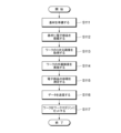
- FIG. 4 is a flow chart schematically showing the first half process of resin sealing.
- FIG. 5 is a flow chart schematically showing the latter half of the resin sealing process.
- the base material S is prepared (S111), and the electronic component P is mounted on the base material S (S112).
- a three-dimensional image of the workpiece W is obtained (S113).
- the measurement device 200 installed in the production line of the work W captures images of the work W from eight directions to obtain a three-dimensional image of the work W.
- the workpiece W is visually inspected (S114). Based on the three-dimensional image of the workpiece W acquired in step S113, the mounting status of the electronic components P, the status of the base material S, and the like are inspected to detect partially defective workpieces W or wholly defective workpieces W.
- the volume of the electronic component P is measured (S115). Based on the three-dimensional image of the electronic component P included in the three-dimensional image of the workpiece W acquired in step S113, the dimensions of the electronic component P are calculated by image analysis. Thereby, the measuring device 200 calculates a volume value indicating the total volume of the electronic component P, which corresponds to the resin supply data.
- the measuring device 200 transmits the resin supply data and the identification data corresponding to the resin supply data to the acquisition unit 110 of the control unit 100 .
- the work W is set in the work magazine WM (S117).
- a workpiece W measured by the measuring device 200 is set in the workpiece magazine WM.
- the step S117 of setting the work W in the work magazine WM may be performed before the step S116 of transmitting the data. For example, after setting the work W in the work magazine WM, only the resin supply data of the work W set in the work magazine WM may be transmitted.
- the acquisition unit 110 receives the resin supply data transmitted by the measuring device 200 and the identification data corresponding to the resin supply data and registers them in the storage unit 120 .
- a database containing a plurality of resin supply data and a plurality of identification data is created in the storage unit 120 .
- the work magazine WM is set in the work storage section 11 (S122).
- Data regarding the work W set in the work magazine WM set in the work storage unit 11 is already stored in the storage unit 120 .
- the identification data corresponding to the identification mark attached to the work W and the resin supply data calculated by measuring the work W are used when the work supply unit 10 is ready to supply the work W. It has already been stored in the storage unit 120 .
- the identification mark of the work W is read (S124).
- the timing of reading the identification mark of the work W is not particularly limited as long as the work W is sent out from the work storage unit 11 .
- the reading unit 130 may read the identification mark from the work W that is being moved from the work storage unit 11 to the work transfer unit 13, or may read the identification mark from the work W set in the work transfer unit 13. . Further, the reading unit 130 may read the identification mark from the work W that is being moved from the work transfer unit 13 to the work preheating unit 15 , or read the identification mark from the work set in the work preheating unit 15 .
- the resin supply data associated with the identification mark is extracted (S125). Based on the identification mark read by the reading unit 130 , the extraction unit 140 extracts resin supply data associated with the identification mark from the storage unit 120 .
- the calculation unit 150 calculates an appropriate supply amount of the resin R based on the resin supply data extracted by the extraction unit 140, and calculates control data for supplying an appropriate supply amount of the resin R to the workpiece W.
- the resin R is supplied to the workpiece W (S127).
- the flow control valve 45 of the resin supply unit 41 is controlled to supply a predetermined amount of resin R optimized for the workpiece W.
- the resin sealing apparatus 1 includes the reading unit 130 for reading the identification mark associated with the resin supply data from the workpiece W, and the workpiece W is detected based on the resin supply data. A predetermined amount of resin R is supplied to . Further, in a resin sealing method according to another aspect of the present invention, the electronic component P is resin-sealed using the resin sealing apparatus 1 .
- the identification mark associated with the resin supply data in advance is used. you should read it.
- the time required to read the identification mark is shorter than the time required to measure the volume of the electronic component P. Therefore, compared to the configuration in which the volume of the electronic component P is measured after the workpiece W is supplied, the time required from the supply of the workpiece W to the molding of the resin R can be shortened, and the manufacturing efficiency can be improved. . In particular, if the volume of the electronic component P is measured more accurately and the supply amount of the resin R is determined more accurately, the time required to measure the volume of the electronic component P becomes longer.
- the time required from the supply of the work W to the molding of the resin R is not affected by the time required to measure the volume of the electronic component P.
- the precision of the supply amount of R can be improved. Therefore, it is possible to reduce the occurrence of defective products and improve manufacturing efficiency.
- the work W supplied in the work supply unit 10 is stored in the work magazine WM after being measured by the measuring device 200, and the reading section 130 reads the identification mark of the work W sent out from the work magazine WM. .
- the identification mark may be attached to the work magazine, and the reading unit may read the identification mark attached to the work magazine.
- an identification mark attached to a work magazine is associated with a plurality of resin supply data for a plurality of works accommodated in the work magazine.
- the amount of resin R to be supplied to each of the plurality of works stored in the work magazine can be calculated. good. Therefore, the time required from the supply of the work W to the molding of the resin R can be further shortened. Moreover, the supply of the resin R can be started before the works W are sent out from the work magazine WM, that is, when the works W are stored in the work magazine WM.
- the resin sealing apparatus 1 separately includes the first loader 60 that transports the work W and the second loader 70 that transports the resin R, and before the work W is placed on the first loader 60 , start supplying the resin R to the second loader 70 .
- the supply of the resin R can be started without waiting for preparation such as preheating of the work W, so that the manufacturing efficiency can be further improved.
- the resin sealing device 1 acquires resin supply data from the external measuring device 200 .
- the size of the resin sealing device 1 can be reduced. In particular, even if the volume of the electronic component P is measured with the large measuring device 200 in order to improve the accuracy of the supply amount of the resin R, the resin sealing device 1 does not become large.
- the resin sealing device 1 is communicably connected to the measuring device 200 .
- the resin sealing apparatus 1 acquires the resin supply data from the measuring apparatus 200 by communication, when the resin supply data is read from a storage medium such as a USB memory, or when the resin supply data is input by an input device such as a keyboard, The time required to acquire the resin supply data can be shortened as compared with the case of inputting the data.
- the resin sealing apparatus 1 may be connected to the measuring device 200 in such a manner that the workpiece W or the workpiece magazine WM can be directly received from the measuring device 200 .
- a pick-and-place hand, a guide rail, a linear conveyor, or the like for transporting the work W or the work magazine WM may be provided.
- the measuring device 200 may be arranged in front, rear or left of the work supply unit 10 . Also, the measuring device 200 may be provided inside the work supply unit 10 . At this time, the work storage unit 11 may be omitted and the work W may be supplied from the measuring device 200 to the work transfer unit 13 .
- the resin sealing apparatus 1 may acquire resin supply data via a storage medium or an input device. According to this, even when the resin sealing device 1 and the measuring device 200 are not connected for communication or the communication is temporarily interrupted, the resin sealing device 1 acquires the resin supply data. can do. In particular, when using a storage medium, the resin sealing apparatus 1 can acquire a large amount of resin supply data at high speed compared to when using an input device.
- the resin supply data is calculated based on a three-dimensional image formed by imaging the workpiece W from eight directions.
- the volume can be calculated with high accuracy, so that the accuracy of the resin supply data can be improved and the occurrence of defective products can be reduced. can.
- the time required for volume measurement may become longer. Calculation of supply data is complete. Therefore, it is possible to improve the accuracy of the resin supply data and reduce the occurrence of defective products without lowering the manufacturing efficiency.
- the resin supply data acquired by the control unit 100 from the measuring device 200 in the above embodiment is the volume value of the electronic component P
- the resin supply data is not limited to the above.
- the resin supply data may be, for example, the amount of resin to be supplied calculated based on the volume value, the dimension value such as the thickness of the electronic component, or the mass value of the electronic component.
- the resin supply data may be control data for controlling the flow rate adjustment valve 45 of the resin supply section 41 . That is, the calculation unit of the control unit may be omitted, and the control unit 100 may control the supply amount of the resin R based on the resin supply data extracted by the extraction unit based on the identification mark.
- the resin supply unit 40 is provided between the resin molding unit 20 and the resin molding unit 30 in this embodiment, either one of the resin molding unit 20 and the resin molding unit 30 may be omitted. That is, one resin supply unit may supply resin to one resin molding unit. Also, three or more resin molding units may be provided, and two or more resin supply units may be provided. For example, two resin molding units and a resin supply unit provided between the two resin molding units to supply resin to the two resin molding units constitute one unit group, and a plurality of unit groups are arranged in the horizontal direction. may be placed side by side. At this time, the control section 100 may control a plurality of resin supply sections of a plurality of resin supply units.
- the first loader 60 functions as a work loader that loads the workpiece W into the molds 21 and 31 and also functions as a molded product unloader that unloads the molded product M from the molds 21 and 31.
- the functionality of the first loader 60 may be limited to a work loader. That is, the resin sealing apparatus may further include a third loader as a molded article unloader. Such a third loader may share a transport path with the first loader, for example, and may be configured to be movable along the first guide section. Also, the resin sealing apparatus may further include a third guide section for conveying the third loader.
- the first loader 60 transports the work W and the molded product M between units, but it is not limited to this.
- the work preheating section and the molded product receiving section may be configured to be movable left and right along the first guide section.
- the work preheating section may convey the work from the work supply unit to the resin molding unit, and deliver the work to a loader provided in the resin molding unit.
- the molded article receiving section may receive the molded article from the loader in the resin molding unit and convey the molded article from the resin molding unit to the molded article collection unit.
- Such a loader may be provided in each of the plurality of resin molding units when the resin sealing apparatus includes a plurality of resin molding units, or may be configured to be movable in the left-right direction between the plurality of resin molding units. may be
- the second loader hand 71 moves between positions P1 to P3 by turning, but the second loader hand 71 may not turn.
- the second loader hand can move in two directions, that is, the front-rear direction and the left-right direction, the second loader hand does not have to move between the positions P1 to P3 by turning.
- the second guide rod can move in the left-right direction. It need not be pivotable as long as it can extend and retract.
- the resin molding units 20 and 30 according to the present embodiment are, for example, compression molding units having a compression molding mold with a movable cavity structure in which the volume of the cavity decreases as the mold is clamped.
- the resin molding units 20 and 30 are not limited to the above, and may be a transfer molding unit having a transfer molding die provided with a mechanism for pressurizing and injecting resin into a fixed-capacity cavity.
- the resin sealing apparatus according to the present embodiment may be either a compression type resin sealing apparatus or a transfer type resin sealing apparatus.
- the cavity is provided on either one of the surfaces of the upper mold and the lower mold that face each other, but may be provided on both.
- a resin sealing device may include a vibration control section instead of the flow control valve 45 as an adjustment section for adjusting the supply speed and supply amount of the resin R.
- the vibration control unit controls the direction, speed, amplitude, etc. of vibration of the feeder 43 to adjust the delivery speed and delivery amount of the resin R delivered by the feeder 43 .
- the movable part which contacts resin R can be reduced. Therefore, it is possible to suppress the occurrence of malfunction of the resin sealing device due to the resin R sticking to the movable portion. Also, by omitting the flow control valve 45, the maintainability of the resin sealing device is improved.
- the adjustment unit is not limited to the flow rate adjustment valve 45 as long as the supply speed and supply amount of the resin R can be adjusted.
- the resin sealing device may further include a correction section that corrects the adjustment of the supply speed or supply amount of the resin R in the adjustment section.
- the correction unit has a weighing device for weighing the resin R, for example.
- the weighing instrument measures the amount of resin R being supplied to the second loader hand 71 or the amount of resin R that has been completely supplied to the second loader hand 71 .
- the weighing instrument may, for example, measure the amount of decrease in resin R contained in the hopper 42 or measure the amount of increase in resin R contained in the second loader hand 71 .
- the resin sealing device may correct the adjustment of the supply speed or supply amount of the resin R being supplied based on the measurement data acquired by the measurement unit, and the supply speed or supply amount of the resin R to be supplied next may be corrected. may be corrected.
- the measurement data is sent to the calculation unit 150 and used to calculate control data for supplying an appropriate amount of resin R to the work W.
- FIG. According to this, the resin R can be supplied more accurately by grasping the supply amount of the resin R not only as a set value in the adjustment section but also as an actual measurement value in the correction section.
- the resin sealing apparatus further includes a sheet resin supply unit that supplies sheet-shaped resin (hereinafter referred to as "sheet resin") molded in the resin molding units 20 and 30. good too.
- sheet resin is used together with the resin R supplied from the resin supply unit 40 for resin sealing of the electronic component P in the resin molding units 20 and 30 . According to this, since the amount of resin R supplied from the resin supply unit 40 in one resin molding can be reduced, the number of times the resin R is supplied to the resin supply unit 40 can be reduced.
- the sheet resin supply unit is arranged, for example, behind the resin supply unit 40, but is not limited to this.
- the sheet resin supply unit may be arranged in front of the functional member supply unit 50 or may be arranged between the resin supply unit 40 and the functional member supply unit 50 .
- the sheet resin supply unit may be arranged in front of or behind the work supply unit 10 , the resin molding units 20 and 30 , or the molded product recovery unit 90 .
- the sheet resin is transported by the second loader 70, for example. According to this, since the sheet resin SR, the resin R, and the functional member H can all be transported by the second loader 70, complication of the resin sealing apparatus due to additional loaders can be suppressed. Note that the sheet resin may be transported by the first loader 60 or may be transported by another loader.
- the second loader 70 transfers the sheet resin supplied from the sheet resin supply unit and the resin R supplied from the resin supply unit 40 to the resin molding units in random order. 20, 30, or simultaneously to the resin molding units 20, 30.
- the second loader 70 conveys the resin R placed on the sheet resin.
- the production speed of the molded product M is improved compared to a resin sealing apparatus in which these are separately conveyed.
- the resin R is transported in a state of being fused to the sheet resin by preheating.
- the position of the resin supplied from the resin supply unit 40 with respect to the sheet resin can be suppressed from changing during transportation, so that the adjustment accuracy of the resin supply position can be improved. can.
- the sheet resin supplied from the sheet resin supply unit and the resin R supplied from the resin supply unit 40 have the same composition. According to this, by adjusting the supply amount of the resin R, the total supply amount of the resin supplied to the resin molding units 20 and 30 can be adjusted without adjusting the shape and size of the sheet resin. can.
- the sheet resin supplied from the sheet resin supply unit and the resin R supplied from the resin supply unit 40 may be resins having different compositions.
- a low-viscosity resin that easily penetrates into details of the work W may be supplied to the side closer to the work W from the viewpoint of suppressing the occurrence of defects due to voids.
- the sheet resin supply unit and the resin supply unit 40 may supply two types of resins that change the curing conditions and physical properties of the cured product when cured together.
- a resin sealing device may include a sheet resin supply unit instead of the functional member supply unit 50 that supplies the functional member H.
Landscapes
- Engineering & Computer Science (AREA)
- Mechanical Engineering (AREA)
- Encapsulation Of And Coatings For Semiconductor Or Solid State Devices (AREA)
Priority Applications (1)
| Application Number | Priority Date | Filing Date | Title |
|---|---|---|---|
| JP2023564745A JPWO2023100439A1 (https=) | 2021-12-03 | 2022-09-14 |
Applications Claiming Priority (2)
| Application Number | Priority Date | Filing Date | Title |
|---|---|---|---|
| JP2021-196756 | 2021-12-03 | ||
| JP2021196756 | 2021-12-03 |
Publications (1)
| Publication Number | Publication Date |
|---|---|
| WO2023100439A1 true WO2023100439A1 (ja) | 2023-06-08 |
Family
ID=86611909
Family Applications (1)
| Application Number | Title | Priority Date | Filing Date |
|---|---|---|---|
| PCT/JP2022/034308 Ceased WO2023100439A1 (ja) | 2021-12-03 | 2022-09-14 | 樹脂封止装置及び樹脂封止方法 |
Country Status (3)
| Country | Link |
|---|---|
| JP (1) | JPWO2023100439A1 (https=) |
| TW (1) | TWI820948B (https=) |
| WO (1) | WO2023100439A1 (https=) |
Citations (2)
| Publication number | Priority date | Publication date | Assignee | Title |
|---|---|---|---|---|
| JP2019145548A (ja) * | 2018-02-16 | 2019-08-29 | アピックヤマダ株式会社 | 樹脂モールド装置及び樹脂モールド方法 |
| WO2020137386A1 (ja) * | 2018-12-27 | 2020-07-02 | アピックヤマダ株式会社 | 樹脂モールド装置 |
Family Cites Families (4)
| Publication number | Priority date | Publication date | Assignee | Title |
|---|---|---|---|---|
| JP4927653B2 (ja) * | 2007-07-10 | 2012-05-09 | 住友重機械工業株式会社 | 樹脂封止装置 |
| CN202962899U (zh) * | 2012-11-02 | 2013-06-05 | 苏州富士胶片映像机器有限公司 | 一种注塑用树脂的自动分检系统 |
| TWI787411B (zh) * | 2018-02-16 | 2022-12-21 | 日商山田尖端科技股份有限公司 | 樹脂模製裝置 |
| JP7618961B2 (ja) * | 2020-02-26 | 2025-01-22 | I-Pex株式会社 | 樹脂封止装置 |
-
2022
- 2022-09-14 JP JP2023564745A patent/JPWO2023100439A1/ja active Pending
- 2022-09-14 WO PCT/JP2022/034308 patent/WO2023100439A1/ja not_active Ceased
- 2022-10-04 TW TW111137614A patent/TWI820948B/zh active
Patent Citations (2)
| Publication number | Priority date | Publication date | Assignee | Title |
|---|---|---|---|---|
| JP2019145548A (ja) * | 2018-02-16 | 2019-08-29 | アピックヤマダ株式会社 | 樹脂モールド装置及び樹脂モールド方法 |
| WO2020137386A1 (ja) * | 2018-12-27 | 2020-07-02 | アピックヤマダ株式会社 | 樹脂モールド装置 |
Also Published As
| Publication number | Publication date |
|---|---|
| TWI820948B (zh) | 2023-11-01 |
| TW202323061A (zh) | 2023-06-16 |
| JPWO2023100439A1 (https=) | 2023-06-08 |
Similar Documents
| Publication | Publication Date | Title |
|---|---|---|
| KR102049609B1 (ko) | 수지몰드장치 | |
| JP5793806B2 (ja) | 樹脂モールド装置 | |
| CN110154300B (zh) | 树脂模制装置以及树脂模制方法 | |
| JP5731009B2 (ja) | 樹脂封止装置および樹脂供給装置 | |
| JP5693931B2 (ja) | 樹脂モールド装置 | |
| KR102288581B1 (ko) | 수지 성형 장치 및 수지 성형품의 제조 방법 | |
| JP7444453B2 (ja) | 樹脂封止装置及び樹脂封止方法 | |
| KR102010643B1 (ko) | 수지 성형 장치, 수지 성형품의 제조 방법 및 제품의 제조 방법 | |
| JP2019145548A (ja) | 樹脂モールド装置及び樹脂モールド方法 | |
| JP5913654B2 (ja) | 樹脂モールド装置及び樹脂モールド方法 | |
| WO2023100439A1 (ja) | 樹脂封止装置及び樹脂封止方法 | |
| JP2023109602A (ja) | 樹脂封止装置及び樹脂封止方法 | |
| JP7603345B2 (ja) | 樹脂封止装置 | |
| KR101087697B1 (ko) | 와이어 검사형 디스펜싱 방법 및 와이어 검사형 디스펜서 | |
| JP2019145549A (ja) | 樹脂モールド装置 | |
| US20250096015A1 (en) | Resin sealing device and resin sealing method | |
| KR102930292B1 (ko) | 수지 밀봉 장치 및 수지 밀봉 방법 | |
| JP2023072436A (ja) | 樹脂封止装置及び樹脂封止方法 | |
| JP2021118244A (ja) | 樹脂モールド装置及び樹脂モールド方法 | |
| JP2023079295A (ja) | 樹脂封止装置 | |
| JP2024014455A (ja) | 樹脂封止装置及び樹脂封止方法 |
Legal Events
| Date | Code | Title | Description |
|---|---|---|---|
| 121 | Ep: the epo has been informed by wipo that ep was designated in this application |
Ref document number: 22900874 Country of ref document: EP Kind code of ref document: A1 |
|
| WWE | Wipo information: entry into national phase |
Ref document number: 2023564745 Country of ref document: JP |
|
| NENP | Non-entry into the national phase |
Ref country code: DE |
|
| 122 | Ep: pct application non-entry in european phase |
Ref document number: 22900874 Country of ref document: EP Kind code of ref document: A1 |