WO2023095822A1 - 車両用駆動装置 - Google Patents
車両用駆動装置 Download PDFInfo
- Publication number
- WO2023095822A1 WO2023095822A1 PCT/JP2022/043312 JP2022043312W WO2023095822A1 WO 2023095822 A1 WO2023095822 A1 WO 2023095822A1 JP 2022043312 W JP2022043312 W JP 2022043312W WO 2023095822 A1 WO2023095822 A1 WO 2023095822A1
- Authority
- WO
- WIPO (PCT)
- Prior art keywords
- gear
- axial direction
- gear mechanism
- axial
- vehicle drive
- Prior art date
- Legal status (The legal status is an assumption and is not a legal conclusion. Google has not performed a legal analysis and makes no representation as to the accuracy of the status listed.)
- Ceased
Links
Images





Classifications
-
- H—ELECTRICITY
- H02—GENERATION; CONVERSION OR DISTRIBUTION OF ELECTRIC POWER
- H02K—DYNAMO-ELECTRIC MACHINES
- H02K7/00—Arrangements for handling mechanical energy structurally associated with dynamo-electric machines, e.g. structural association with mechanical driving motors or auxiliary dynamo-electric machines
- H02K7/10—Structural association with clutches, brakes, gears, pulleys or mechanical starters
- H02K7/116—Structural association with clutches, brakes, gears, pulleys or mechanical starters with gears
-
- B—PERFORMING OPERATIONS; TRANSPORTING
- B60—VEHICLES IN GENERAL
- B60K—ARRANGEMENT OR MOUNTING OF PROPULSION UNITS OR OF TRANSMISSIONS IN VEHICLES; ARRANGEMENT OR MOUNTING OF PLURAL DIVERSE PRIME-MOVERS IN VEHICLES; AUXILIARY DRIVES FOR VEHICLES; INSTRUMENTATION OR DASHBOARDS FOR VEHICLES; ARRANGEMENTS IN CONNECTION WITH COOLING, AIR INTAKE, GAS EXHAUST OR FUEL SUPPLY OF PROPULSION UNITS IN VEHICLES
- B60K1/00—Arrangement or mounting of electrical propulsion units
-
- B—PERFORMING OPERATIONS; TRANSPORTING
- B60—VEHICLES IN GENERAL
- B60K—ARRANGEMENT OR MOUNTING OF PROPULSION UNITS OR OF TRANSMISSIONS IN VEHICLES; ARRANGEMENT OR MOUNTING OF PLURAL DIVERSE PRIME-MOVERS IN VEHICLES; AUXILIARY DRIVES FOR VEHICLES; INSTRUMENTATION OR DASHBOARDS FOR VEHICLES; ARRANGEMENTS IN CONNECTION WITH COOLING, AIR INTAKE, GAS EXHAUST OR FUEL SUPPLY OF PROPULSION UNITS IN VEHICLES
- B60K17/00—Arrangement or mounting of transmissions in vehicles
- B60K17/04—Arrangement or mounting of transmissions in vehicles characterised by arrangement, location or kind of gearing
- B60K17/16—Arrangement or mounting of transmissions in vehicles characterised by arrangement, location or kind of gearing of differential gearing
- B60K17/165—Arrangement or mounting of transmissions in vehicles characterised by arrangement, location or kind of gearing of differential gearing provided between independent half axles
-
- B—PERFORMING OPERATIONS; TRANSPORTING
- B60—VEHICLES IN GENERAL
- B60L—PROPULSION OF ELECTRICALLY-PROPELLED VEHICLES; SUPPLYING ELECTRIC POWER FOR AUXILIARY EQUIPMENT OF ELECTRICALLY-PROPELLED VEHICLES; ELECTRODYNAMIC BRAKE SYSTEMS FOR VEHICLES IN GENERAL; MAGNETIC SUSPENSION OR LEVITATION FOR VEHICLES; MONITORING OPERATING VARIABLES OF ELECTRICALLY-PROPELLED VEHICLES; ELECTRIC SAFETY DEVICES FOR ELECTRICALLY-PROPELLED VEHICLES
- B60L15/00—Methods, circuits, or devices for controlling the traction-motor speed of electrically-propelled vehicles
- B60L15/007—Physical arrangements or structures of drive train converters specially adapted for the propulsion motors of electric vehicles
-
- F—MECHANICAL ENGINEERING; LIGHTING; HEATING; WEAPONS; BLASTING
- F16—ENGINEERING ELEMENTS AND UNITS; GENERAL MEASURES FOR PRODUCING AND MAINTAINING EFFECTIVE FUNCTIONING OF MACHINES OR INSTALLATIONS; THERMAL INSULATION IN GENERAL
- F16H—GEARING
- F16H37/00—Combinations of mechanical gearings, not provided for in groups F16H1/00 - F16H35/00
- F16H37/02—Combinations of mechanical gearings, not provided for in groups F16H1/00 - F16H35/00 comprising essentially only toothed or friction gearings
- F16H37/06—Combinations of mechanical gearings, not provided for in groups F16H1/00 - F16H35/00 comprising essentially only toothed or friction gearings with a plurality of driving or driven shafts; with arrangements for dividing torque between two or more intermediate shafts
- F16H37/08—Combinations of mechanical gearings, not provided for in groups F16H1/00 - F16H35/00 comprising essentially only toothed or friction gearings with a plurality of driving or driven shafts; with arrangements for dividing torque between two or more intermediate shafts with differential gearing
- F16H37/0806—Combinations of mechanical gearings, not provided for in groups F16H1/00 - F16H35/00 comprising essentially only toothed or friction gearings with a plurality of driving or driven shafts; with arrangements for dividing torque between two or more intermediate shafts with differential gearing with a plurality of driving or driven shafts
- F16H37/0813—Combinations of mechanical gearings, not provided for in groups F16H1/00 - F16H35/00 comprising essentially only toothed or friction gearings with a plurality of driving or driven shafts; with arrangements for dividing torque between two or more intermediate shafts with differential gearing with a plurality of driving or driven shafts with only one input shaft
- F16H37/082—Combinations of mechanical gearings, not provided for in groups F16H1/00 - F16H35/00 comprising essentially only toothed or friction gearings with a plurality of driving or driven shafts; with arrangements for dividing torque between two or more intermediate shafts with differential gearing with a plurality of driving or driven shafts with only one input shaft and additional planetary reduction gears
-
- F—MECHANICAL ENGINEERING; LIGHTING; HEATING; WEAPONS; BLASTING
- F16—ENGINEERING ELEMENTS AND UNITS; GENERAL MEASURES FOR PRODUCING AND MAINTAINING EFFECTIVE FUNCTIONING OF MACHINES OR INSTALLATIONS; THERMAL INSULATION IN GENERAL
- F16H—GEARING
- F16H57/00—General details of gearing
- F16H57/04—Features relating to lubrication or cooling or heating
- F16H57/042—Guidance of lubricant
- F16H57/0421—Guidance of lubricant on or within the casing, e.g. shields or baffles for collecting lubricant, tubes, pipes, grooves, channels or the like
- F16H57/0423—Lubricant guiding means mounted or supported on the casing, e.g. shields or baffles for collecting lubricant, tubes or pipes
-
- F—MECHANICAL ENGINEERING; LIGHTING; HEATING; WEAPONS; BLASTING
- F16—ENGINEERING ELEMENTS AND UNITS; GENERAL MEASURES FOR PRODUCING AND MAINTAINING EFFECTIVE FUNCTIONING OF MACHINES OR INSTALLATIONS; THERMAL INSULATION IN GENERAL
- F16H—GEARING
- F16H57/00—General details of gearing
- F16H57/04—Features relating to lubrication or cooling or heating
- F16H57/045—Lubricant storage reservoirs, e.g. reservoirs in addition to a gear sump for collecting lubricant in the upper part of a gear case
-
- H—ELECTRICITY
- H02—GENERATION; CONVERSION OR DISTRIBUTION OF ELECTRIC POWER
- H02K—DYNAMO-ELECTRIC MACHINES
- H02K11/00—Structural association of dynamo-electric machines with electric components or with devices for shielding, monitoring or protection
- H02K11/30—Structural association with control circuits or drive circuits
- H02K11/33—Drive circuits, e.g. power electronics
-
- B—PERFORMING OPERATIONS; TRANSPORTING
- B60—VEHICLES IN GENERAL
- B60K—ARRANGEMENT OR MOUNTING OF PROPULSION UNITS OR OF TRANSMISSIONS IN VEHICLES; ARRANGEMENT OR MOUNTING OF PLURAL DIVERSE PRIME-MOVERS IN VEHICLES; AUXILIARY DRIVES FOR VEHICLES; INSTRUMENTATION OR DASHBOARDS FOR VEHICLES; ARRANGEMENTS IN CONNECTION WITH COOLING, AIR INTAKE, GAS EXHAUST OR FUEL SUPPLY OF PROPULSION UNITS IN VEHICLES
- B60K1/00—Arrangement or mounting of electrical propulsion units
- B60K2001/001—Arrangement or mounting of electrical propulsion units one motor mounted on a propulsion axle for rotating right and left wheels of this axle
-
- B—PERFORMING OPERATIONS; TRANSPORTING
- B60—VEHICLES IN GENERAL
- B60K—ARRANGEMENT OR MOUNTING OF PROPULSION UNITS OR OF TRANSMISSIONS IN VEHICLES; ARRANGEMENT OR MOUNTING OF PLURAL DIVERSE PRIME-MOVERS IN VEHICLES; AUXILIARY DRIVES FOR VEHICLES; INSTRUMENTATION OR DASHBOARDS FOR VEHICLES; ARRANGEMENTS IN CONNECTION WITH COOLING, AIR INTAKE, GAS EXHAUST OR FUEL SUPPLY OF PROPULSION UNITS IN VEHICLES
- B60K7/00—Disposition of motor in, or adjacent to, traction wheel
- B60K2007/0061—Disposition of motor in, or adjacent to, traction wheel the motor axle being parallel to the wheel axle
-
- F—MECHANICAL ENGINEERING; LIGHTING; HEATING; WEAPONS; BLASTING
- F16—ENGINEERING ELEMENTS AND UNITS; GENERAL MEASURES FOR PRODUCING AND MAINTAINING EFFECTIVE FUNCTIONING OF MACHINES OR INSTALLATIONS; THERMAL INSULATION IN GENERAL
- F16H—GEARING
- F16H1/00—Toothed gearings for conveying rotary motion
- F16H1/02—Toothed gearings for conveying rotary motion without gears having orbital motion
- F16H1/04—Toothed gearings for conveying rotary motion without gears having orbital motion involving only two intermeshing members
- F16H1/06—Toothed gearings for conveying rotary motion without gears having orbital motion involving only two intermeshing members with parallel axes
- F16H1/08—Toothed gearings for conveying rotary motion without gears having orbital motion involving only two intermeshing members with parallel axes the members having helical, herringbone, or like teeth
-
- F—MECHANICAL ENGINEERING; LIGHTING; HEATING; WEAPONS; BLASTING
- F16—ENGINEERING ELEMENTS AND UNITS; GENERAL MEASURES FOR PRODUCING AND MAINTAINING EFFECTIVE FUNCTIONING OF MACHINES OR INSTALLATIONS; THERMAL INSULATION IN GENERAL
- F16H—GEARING
- F16H1/00—Toothed gearings for conveying rotary motion
- F16H1/28—Toothed gearings for conveying rotary motion with gears having orbital motion
- F16H2001/2881—Toothed gearings for conveying rotary motion with gears having orbital motion comprising two axially spaced central gears, i.e. ring or sun gear, engaged by at least one common orbital gear wherein one of the central gears is forming the output
-
- F—MECHANICAL ENGINEERING; LIGHTING; HEATING; WEAPONS; BLASTING
- F16—ENGINEERING ELEMENTS AND UNITS; GENERAL MEASURES FOR PRODUCING AND MAINTAINING EFFECTIVE FUNCTIONING OF MACHINES OR INSTALLATIONS; THERMAL INSULATION IN GENERAL
- F16H—GEARING
- F16H48/00—Differential gearings
- F16H48/06—Differential gearings with gears having orbital motion
- F16H48/08—Differential gearings with gears having orbital motion comprising bevel gears
-
- F—MECHANICAL ENGINEERING; LIGHTING; HEATING; WEAPONS; BLASTING
- F16—ENGINEERING ELEMENTS AND UNITS; GENERAL MEASURES FOR PRODUCING AND MAINTAINING EFFECTIVE FUNCTIONING OF MACHINES OR INSTALLATIONS; THERMAL INSULATION IN GENERAL
- F16H—GEARING
- F16H57/00—General details of gearing
- F16H57/04—Features relating to lubrication or cooling or heating
- F16H57/0457—Splash lubrication
-
- F—MECHANICAL ENGINEERING; LIGHTING; HEATING; WEAPONS; BLASTING
- F16—ENGINEERING ELEMENTS AND UNITS; GENERAL MEASURES FOR PRODUCING AND MAINTAINING EFFECTIVE FUNCTIONING OF MACHINES OR INSTALLATIONS; THERMAL INSULATION IN GENERAL
- F16H—GEARING
- F16H57/00—General details of gearing
- F16H57/04—Features relating to lubrication or cooling or heating
- F16H57/048—Type of gearings to be lubricated, cooled or heated
- F16H57/0482—Gearings with gears having orbital motion
- F16H57/0483—Axle or inter-axle differentials
Definitions
- the present invention comprises a rotating electrical machine having a rotor, an output member drivingly connected to wheels, a power transmission mechanism for transmitting rotation of the rotor to the output member, and a torque transmitted to the output member being distributed to a pair of wheels. and a differential gear mechanism.
- Patent Document 1 An example of such a vehicle driving device is disclosed in Patent Document 1 below.
- reference numerals in Patent Document 1 are quoted in parentheses.
- a transmission gear mechanism (21) is a power transmission mechanism that transmits the rotation of a rotor (12) of a rotating electrical machine (1) to a differential case (33) as an output member. , a transmission output gear (22) to which the rotation after shifting by the transmission gear mechanism (21) is transmitted, and a differential input gear (31) that meshes with the transmission output gear (22).
- a differential gear mechanism (3) distributes the rotation transmitted to the differential input gear (31) to a pair of wheels (W).
- the differential input gear (31) is arranged so as to overlap with both the rotating electric machine (1) and the speed change gear mechanism (21) when viewed in the axial direction. This suppresses an increase in size in the radial direction (R) of the device (100).
- the characteristic configuration of the vehicle drive system is as follows.
- a rotating electric machine having a rotor; an output member drivingly connected to a wheel provided on the vehicle; a power transmission mechanism that transmits rotation of the rotor to the output member; a differential gear mechanism for distributing the torque transmitted to the output member to the pair of wheels,
- the power transmission mechanism includes a planetary gear mechanism, a first gear, and a second gear, the second gear meshes with the first gear and is connected to rotate integrally with the output member;
- a direction along the rotation axis of the rotor is defined as an axial direction, one side in the axial direction is defined as a first side in the axial direction, and the other side in the axial direction is defined as a second side in the axial direction.
- the differential gear mechanism is connected to the target wheel via a connecting member,
- the rotor, the planetary gear mechanism, and the first gear are arranged on a first shaft in the order described from the first side in the axial direction toward the second side in the axial direction,
- the connecting member, the differential gear mechanism, and the second gear are arranged on a second axis parallel to the first axis in the order described from the first side in the axial direction toward the second side in the axial direction.
- the planetary gear mechanism has a diameter smaller than that of the rotating electric machine and a diameter larger than that of the first gear;
- the differential gear mechanism has a smaller diameter than the second gear and a larger diameter than the connecting member.
- the rotating electric machine, the planetary gear mechanism, and the first gear arranged on the first shaft have radial dimensions that gradually decrease from the first side in the axial direction toward the second side in the axial direction.
- the connecting member, the differential gear mechanism, and the second gear, which are arranged in order and are arranged on the second shaft, are arranged in order of increasing radial dimension from the first side in the axial direction to the second side in the axial direction. are placed in Therefore, it becomes easy to keep the inter-axis distance between the first axis and the second axis short while avoiding interference between the elements on the first axis and the elements on the second axis. It is easy to keep the dimensions of
- FIG. 1 is a skeleton diagram of a vehicle drive system according to a first embodiment
- FIG. 2 is a diagram showing the positional relationship of each element in the vehicle drive system according to the first embodiment when viewed in the axial direction
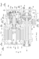
- Sectional view along the axial direction of the vehicle drive device according to the second embodiment Sectional view along the axial direction of the vehicle drive device according to the third embodiment
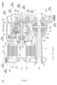
- Sectional view along the axial direction of the vehicle drive device according to the fourth embodiment A view of the inside of the case of the vehicle drive device according to the fourth embodiment, viewed from the second side in the axial direction.
- FIG. 11 is a view of the vehicle drive device according to the fourth embodiment viewed in a horizontal direction orthogonal to the axial direction;
- the vehicle drive device 100 includes a rotating electric machine 1 , an output member 2 and a power transmission mechanism 3 .
- the vehicle drive device 100 further includes a differential gear mechanism 4 and a case 9 .
- the rotating electric machine 1 has a stator 11 and a rotor 12 .
- An axial direction L which will be described later, is a direction along the rotation axis of the rotor 12 .
- the rotating electric machine 1 functions as a driving force source for the wheels W (see FIG. 2).
- the rotary electric machine 1 has a function as a motor (electric motor) that receives power supply and generates power, and a function as a generator (generator) that receives power supply and generates power.
- the rotary electric machine 1 is electrically connected to a power storage device (not shown) such as a battery or a capacitor. Then, the rotating electric machine 1 is powered by the electric power stored in the power storage device to generate a driving force. Further, the rotating electric machine 1 generates power by the driving force transmitted from the wheel W side, and charges the power storage device.
- the output member 2 is drivingly connected to wheels W provided on the vehicle (vehicle on which the vehicle drive device 100 is mounted).
- the power transmission mechanism 3 is configured to transmit rotation of the rotor 12 to the output member 2 .
- the power transmission mechanism 3 includes a planetary gear mechanism 31 , a first gear 32 and a second gear 33 .
- the differential gear mechanism 4 is configured to distribute the torque transmitted to the output member 2 to the pair of wheels W.
- the term “driving connection” refers to a state in which two rotating elements are connected so as to be able to transmit a driving force, and the two rotating elements are connected so as to rotate integrally. It includes a state in which two rotating elements are connected so as to be able to transmit driving force via one or more transmission members.
- Such transmission members include various members that transmit rotation at the same speed or at different speeds, such as shafts, gear mechanisms, belts, and chains.
- the transmission member may include an engagement device for selectively transmitting rotation and driving force, such as a friction engagement device and a mesh type engagement device.
- driving connection it refers to a state in which a plurality of rotating elements in the planetary gear mechanism are connected to each other without interposing other rotating elements.
- the rotor 12, the planetary gear mechanism 31, and the first gear 32 are arranged on the first axis X1 as their axis. Also, the output member 2 and the second gear 33 are arranged on the second axis X2 as their axis. In this embodiment, the differential gear mechanism 4 is also arranged on the second axis X2. The first axis X1 and the second axis X2 are arranged parallel to each other.
- the direction parallel to the first axis X1 and the second axis X2 is the "axial direction L" of the vehicle drive device 100.
- first axial side L1 One side in the axial direction L
- second axial side L2 the other side in the axial direction L
- the first axial side L1 the side on which the rotor 12 is arranged with respect to the planetary gear mechanism 31
- the opposite side is defined as the second axial side L2.
- the direction orthogonal to each of the first axis X1 and the second axis X2 is defined as "radial direction R" with respect to each axis.
- case 9 accommodates the rotating electric machine 1 and the power transmission mechanism 3.
- case 9 also houses output member 2 and differential gear mechanism 4 .
- the case 9 includes a first case portion 91, a second case portion 92 joined to the first case portion 91 from the first side L1 in the axial direction, and a and a third case portion 93 joined from the axial second side L2.
- the first case portion 91 includes a first peripheral wall portion 91a, a second peripheral wall portion 91b, and a partition wall portion 91c.
- the first peripheral wall portion 91a is formed so as to cover the outer side of the rotary electric machine 1 in the radial direction R.
- the second peripheral wall portion 91b is formed so as to cover the outer side of the planetary gear mechanism 31 and the differential gear mechanism 4 in the radial direction R.
- the partition wall portion 91c is formed so as to separate the inner space of the first peripheral wall portion 91a and the inner space of the second peripheral wall portion 91b in the axial direction L from each other.
- the first peripheral wall portion 91a is arranged on the first side L1 in the axial direction with respect to the partition portion 91c
- the second peripheral wall portion 91b is arranged on the second side L2 in the axial direction with respect to the partition portion 91c.
- the first peripheral wall portion 91a is formed in a tubular shape opening on the first side L1 in the axial direction
- the second peripheral wall portion 91b is formed in a tubular shape opening on the second side L2 in the axial direction.
- the second case portion 92 has a first side wall portion 92a.
- the first side wall portion 92a is formed to cover the first axial side L1 of the rotating electrical machine 1 .
- the second case portion 92 is positioned at the first axial direction relative to the first case portion 91 so that the opening on the axial first side L1 of the first peripheral wall portion 91a is closed by the first side wall portion 92a. It is joined from the side L1.
- the third case portion 93 has a second side wall portion 93a.
- the second side wall portion 93a is formed to cover the second axial side L2 of the power transmission mechanism 3 and the differential gear mechanism 4 .
- the third case portion 93 is axially positioned second relative to the first case portion 91 so that the opening on the axial second side L2 of the second peripheral wall portion 91b is closed by the second side wall portion 93a. It is joined from the side L2.
- the stator 11 of the rotating electrical machine 1 has a cylindrical stator core 11a.
- Stator core 11a is fixed to non-rotating member NR.
- the stator core 11a is fixed to the first peripheral wall portion 91a of the case 9 as the non-rotating member NR.
- a rotor 12 of the rotating electric machine 1 includes a cylindrical rotor core 12a.
- the rotor core 12a is rotatably supported with respect to the stator core 11a.
- the rotor 12 further includes a rotor shaft 12b coupled to rotate integrally with the rotor core 12a.
- the rotating electrical machine 1 is an inner rotor type rotating electrical machine. Therefore, the rotor core 12a is arranged inside in the radial direction R with respect to the stator core 11a. Further, the rotor shaft 12b is arranged inside in the radial direction R with respect to the rotor core 12a.
- the rotating electrical machine 1 is a rotating field type rotating electrical machine. Therefore, a stator coil is wound around the stator core 11a.
- the stator coil is wound around the stator core 11a so that a pair of coil end portions 11b projecting to both sides in the axial direction L of the stator core 11a are formed.
- the rotor core 12a is provided with permanent magnets.
- the rotor shaft 12b is formed in a tubular shape having an axial center along the axial direction L. Further, in the present embodiment, the rotor shaft 12b is arranged to protrude from both sides in the axial direction L from the rotor core 12a. A portion of the rotor shaft 12b that protrudes from the rotor core 12a toward the first side L1 in the axial direction is rotatably supported by the first side wall portion 92a of the case 9 via a first rotor bearing B11.
- the portion of the rotor shaft 12b that protrudes from the rotor core 12a to the second side L2 in the axial direction is rotatably supported by the partition wall 91c of the case 9 via the second rotor bearing B12.
- the planetary gear mechanism 31 is configured to decelerate the rotation of the rotor 12 and transmit it to the first gear 32 .
- the planetary gear mechanism 31 includes a sun gear SG, a carrier CR, and a ring gear RG.
- the sun gear SG is connected to rotate integrally with the rotor 12 .
- the sun gear SG is coupled via the input shaft 5 so as to rotate integrally with the rotor shaft 12b.
- the input shaft 5 is formed to extend along the axial direction L.
- the input shaft 5 is formed to extend from the sun gear SG to the first side L1 in the axial direction.
- the input shaft 5 is integrally formed with the sun gear SG.
- the input shaft 5 includes a connecting portion 51 and an enlarged diameter portion 52 .
- the connecting portion 51 is connected to rotate integrally with the rotor shaft 12b.
- the connecting portion 51 is arranged so as to pass through the partition portion 91c of the case 9 in the axial direction L.
- the connecting portion 51 is arranged inside the rotor shaft 12b in the radial direction R and is connected to the rotor shaft 12b by spline engagement.
- the enlarged diameter portion 52 is formed to have a larger diameter than the connecting portion 51 .
- the enlarged diameter portion 52 is arranged on the second axial side L2 with respect to the partition wall portion 91c.
- a first thrust bearing B3 that supports the input shaft 5 in the axial direction L is arranged between the enlarged diameter portion 52 and the partition wall portion 91c in the axial direction L. As shown in FIG.
- the carrier CR rotatably supports the first pinion gear PG1 and the second pinion gear PG2 that rotate integrally with each other.
- the first pinion gear PG1 meshes with the sun gear SG.
- the second pinion gear PG2 meshes with the ring gear RG.
- the second pinion gear PG2 is formed to have a smaller diameter than the first pinion gear PG1.
- the second pinion gear PG2 is arranged on the first side L1 in the axial direction relative to the first pinion gear PG1. That is, in the present embodiment, the second pinion gear PG2 is arranged closer to the rotary electric machine 1 in the axial direction L than the first pinion gear PG1.
- Each of the first pinion gear PG1 and the second pinion gear PG2 rotates (revolves) around its own axis and rotates (revolves) around the sun gear SG together with the carrier CR.
- a plurality of first pinion gears PG1 and second pinion gears PG2 are provided at intervals along their own orbital locus.
- first element E1 one of the carrier CR and the ring gear RG will be referred to as the "first element E1" and the other as the “second element E2".
- the first element E1 is connected to rotate integrally with the first gear 32.
- the carrier CR is connected to the first gear 32 so as to rotate integrally therewith. That is, in this embodiment, the carrier CR is the first element E1.
- the second element E2 is fixed with respect to the non-rotating member NR.
- the ring gear RG is fixed to the second peripheral wall portion 91b of the case 9 as the non-rotating member NR. That is, in this embodiment, the ring gear RG is the second element E2.
- the ring gear RG is fixed to the non-rotating member NR
- the second pinion gear PG2 is arranged closer to the rotary electric machine 1 in the axial direction L than the first pinion gear PG1.
- a support member as a non-rotating member NR is often provided between the rotary electric machine 1 and the planetary gear mechanism 31 in the axial direction L to rotatably support the rotor 12 .
- this configuration it becomes easy to fix the ring gear RG meshing with the second pinion gear PG2 arranged relatively close to the rotary electric machine 1 to the non-rotating member NR.
- the first element E1 has a first connecting portion 311.
- the first gear 32 has a second connecting portion 321 .
- the first connecting portion 311 and the second connecting portion 321 are configured to be connected to each other so as not to rotate relative to each other.
- the first connecting portion 311 is formed in a tubular shape with the first axis X1 as the axis.
- the first connecting portion 311 includes a first engaging portion 311a and a first pressure contact portion 311b.
- the second connecting portion 321 is arranged inside the first connecting portion 311 in the radial direction R. As shown in FIG.
- the second connecting portion 321 includes a second engaging portion 321a and a second pressure contact portion 321b.
- the first engaging portion 311a and the second engaging portion 321a are formed so as to be non-rotatably engaged with each other.
- the first engaging portion 311a extends in the axial direction L and is composed of a plurality of internal teeth arranged in the circumferential direction about the first axis X1.
- the second engaging portion 321a extends in the axial direction L and is composed of a plurality of external teeth arranged in the circumferential direction about the first axis X1.
- the first pressure contact portion 311b and the second pressure contact portion 321b are formed so as to press against each other in the radial direction R so as not to move relative to each other.
- the inner peripheral surface of the first pressure contact portion 311b and the outer peripheral surface of the second pressure contact portion 321b are formed so as to be in pressure contact with each other (in other words, contact with pressure).
- the second press-contact portion 321b is press-fitted or tightly fitted into the first press-contact portion 311b.
- the first pressure contact portion 311b is arranged on the second side L2 in the axial direction from the first engaging portion 311a.
- the second pressure contact portion 321b is arranged on the second side L2 in the axial direction from the second engaging portion 321a.
- the planetary gear mechanism 31 is arranged on the second axial side L2 with respect to the rotary electric machine 1 and on the first axial side L1 with respect to the first gear 32 . That is, in the present embodiment, the rotor 12, the planetary gear mechanism 31, and the first gear 32 are arranged on the first axis X1 from the first axial side L1 toward the second axial side L2 in the order described. ing.
- the rotary electric machine 1 has a larger diameter than the planetary gear mechanism 31 .
- the outer peripheral surface of the stator core 11 a of the rotating electric machine 1 is positioned radially outside the ring gear RG of the planetary gear mechanism 31 at the radially outermost portion.
- the diameter of the first gear 32 is smaller than that of the planetary gear mechanism 31 .
- the portion of the first gear 32 that is located on the outermost side in the radial direction R is radially inward of the portion of the ring gear RG of the planetary gear mechanism 31 that is located on the outermost side in the radial direction R. positioned.
- the planetary gear mechanism 31 has a smaller diameter than the rotary electric machine 1 and a larger diameter than the first gear 32 . Therefore, in the present embodiment, the rotary electric machine 1, the planetary gear mechanism 31, and the first gear 32 are configured such that the dimension in the radial direction R gradually decreases from the axial direction first side L1 toward the axial direction second side L2. , on the first axis X1.
- the first gear 32 is rotatably supported with respect to the case 9 via the first support bearing B2.
- the first support bearing B ⁇ b>2 is arranged inside the first gear 32 in the radial direction R and overlaps the first gear 32 when viewed in the radial direction R.
- "overlapping in a particular direction view” means that when a virtual straight line parallel to the line-of-sight direction is moved in each direction orthogonal to the virtual straight line, the virtual straight line is two It refers to the existence of at least a part of an area that intersects two elements.
- the second side wall portion 93a of the case 9 is arranged adjacent to the first gear 32 on the axial second side L2.
- the second side wall portion 93a functions as a “support wall portion SW” arranged adjacent to the first gear 32 on the side opposite to the planetary gear mechanism 31 side in the axial direction L.
- the second side wall portion 93a is formed with a first projecting portion 93b projecting toward the first side L1 in the axial direction.
- the first projecting portion 93b is formed to support the first support bearing B2 from the inside in the radial direction R.
- the first projecting portion 93b functions as a "bearing support portion SWa" that supports the first support bearing B2 from the inside in the radial direction R.
- the first gear 32 further includes a supported portion 322 .
- the supported portion 322 is arranged between the input shaft 5 and the first projecting portion 93b of the case 9 in the axial direction L. As shown in FIG. In this embodiment, the supported portion 322 is formed to protrude inward in the radial direction R from the second connecting portion 321 .
- the second thrust bearing B4 is arranged between the supported portion 322 and the input shaft 5 in the axial direction L.
- a third thrust bearing B5 is arranged between the supported portion 322 and the first projecting portion 93b in the axial direction L.
- the first gear 32 is supported in the axial direction L with respect to the case 9 by the second thrust bearing B4 and the third thrust bearing B5.
- the second gear 33 meshes with the first gear 32.
- the second gear 33 is connected to rotate integrally with the output member 2 .
- the second gear 33 is formed with a larger diameter than the first gear 32 . Therefore, in this embodiment, the rotation of the first element E ⁇ b>1 (here, the carrier CR) is decelerated between the first gear 32 and the second gear 33 and transmitted to the output member 2 .
- the second gear 33 is rotatably supported with respect to the case 9 via the second support bearing B6.
- the second support bearing B6 is arranged inside the second gear 33 in the radial direction R and overlaps the second gear 33 when viewed in the radial direction R. As shown in FIG.
- the second side wall portion 93a is formed with a second projecting portion 93c projecting toward the first side L1 in the axial direction.
- the second projecting portion 93c is formed to support the second support bearing B6 from the inside in the radial direction R. As shown in FIG.
- each of the first gear 32 and the second gear 33 is a double-helical gear. More specifically, the first gear 32 includes a first meshing portion 32a and a second meshing portion 32b whose teeth are twisted in different directions.
- the second gear 33 also includes a third meshing portion 33a and a fourth meshing portion 33b whose teeth are twisted in different directions.
- the first meshing portion 32a and the third meshing portion 33a mesh with each other, and the second meshing portion 32b and the fourth meshing portion 33b mesh with each other.
- the "torsion direction of the tooth” is the direction in which the tooth of the gear is inclined with respect to the axis of the target gear.
- the thrust force generated by the engagement between the first gear 32 and the second gear 33 can be reduced compared to a configuration in which the first gear 32 and the second gear 33 are simply helical gears.
- the supporting structure of the first gear 32 and the second gear 33 can be simplified. Therefore, it is easy to reduce the size of the vehicle drive device 100 .
- the differential gear mechanism 4 includes a differential case 41, a pair of pinion gears 42, a first side gear 43 and a second side gear 44.
- the pair of pinion gears 42 and the first side gear 43 and the second side gear 44 are all bevel gears.
- the differential case 41 is a hollow member that accommodates a pair of pinion gears 42 and a first side gear 43 and a second side gear 44 .
- the differential case 41 is connected to rotate integrally with the second gear 33 . Therefore, the differential case 41 corresponds to the output member 2 in this embodiment.
- the differential case 41 is rotatably supported with respect to the case 9 via the differential bearing B7.
- the end portion of the differential case 41 on the first side L1 in the axial direction is rotatably supported by the second peripheral wall portion 91b of the case 9 via the differential bearing B7.
- the pair of pinion gears 42 are arranged to face each other with a gap in the radial direction R with respect to the second axis X2.
- the pair of pinion gears 42 are attached to a pinion shaft 42a supported so as to rotate integrally with the differential case 41.
- Each of the pair of pinion gears 42 is configured to be rotatable (rotational) about the pinion shaft 42a and rotatable (orbital) about the second axis X2.
- the first side gear 43 and the second side gear 44 mesh with the pair of pinion gears 42 .
- the first side gear 43 and the second side gear 44 are arranged to rotate about the second axis X2.
- the first side gear 43 is arranged on the first side L1 in the axial direction with respect to the pinion shaft 42a.
- the second side gear 44 is arranged on the second side L2 in the axial direction with respect to the pinion shaft 42a.
- the first side gear 43 is driven by a first drive shaft DS1 (see FIG. 2) to the wheel W on the first side L1 in the axial direction via the transmission shaft 6 extending in the axial direction L. ) so as to rotate together.
- the transmission shaft 6 is inserted from the first side L1 in the axial direction inside the first side gear 43 in the radial direction R, and they are connected to each other by spline engagement.
- the differential gear mechanism 4 is connected to the target wheel WT via the transmission shaft 6.
- the transmission shaft 6 corresponds to the "connecting member".
- the transmission shaft 6 is arranged on the second axis X2.
- the transmission shaft 6 is arranged so as to pass through the outer side of the rotary electric machine 1 in the radial direction R inside the case 9 and penetrate the first side wall portion 92a in the axial direction L.
- the transmission shaft 6 is connected to rotate integrally with the first drive shaft DS1 (see FIG. 2).
- a portion of the transmission shaft 6 closer to the first axial side L1 than the first case portion 91 is formed in a tubular shape that opens to the first axial side L1.
- a first drive shaft DS1 is inserted from a first axial side L1 inside the cylindrical portion of the transmission shaft 6 in the radial direction R, and they are connected to each other by spline engagement.
- the second side gear 44 is connected to rotate integrally with the second drive shaft DS2 (see FIG. 2) drivingly connected to the wheel W on the axial second side L2.
- the second drive shaft DS2 is inserted from the axial second side L2 inside the second side gear 44 in the radial direction R, and they are connected to each other by spline engagement.
- the differential gear mechanism 4 is arranged on the first side L1 in the axial direction with respect to the second gear 33 and on the second side L2 in the axial direction with respect to the transmission shaft 6 . That is, in the present embodiment, the transmission shaft 6, the differential gear mechanism 4, and the second gear 33 are arranged along the second axis X2 parallel to the first axis X1 from the first axial side L1 to the second axial side L1. They are arranged in the order of description toward L2.
- the second gear 33 has a larger diameter than the differential gear mechanism 4.
- the portion of the second gear 33 that is located most outward in the radial direction R is radially outward of the portion of the pinion gear 42 of the differential gear mechanism 4 that is located most outward in the radial direction R. located in
- the transmission shaft 6 has a smaller diameter than the differential gear mechanism 4 .
- the portion of the transmission shaft 6 located on the outermost side in the radial direction R is radially inward of the portion of the pinion gear 42 of the differential gear mechanism 4 located on the outermost side in the radial direction R. positioned.
- the differential gear mechanism 4 has a smaller diameter than the second gear 33 and a larger diameter than the transmission shaft 6 . Therefore, in this embodiment, the transmission shaft 6, the differential gear mechanism 4, and the second gear 33 are configured so that the dimension in the radial direction R gradually increases from the first axial side L1 toward the second axial side L2. , is arranged on the second axis X2.
- Fig. 3 shows the positional relationship of each element housed in the case 9 as seen in the axial direction along the axial direction L. 3 indicates the vertical direction of the vehicle drive device 100 in the vehicle mounting posture.
- vehicle mounting attitude is the attitude of the vehicle drive device 100 when it is mounted on the vehicle.
- the first axis X1 is arranged above the second axis X2 in the vehicle mounting posture.
- 3 indicates a virtual plane passing through the first axis X1 along the horizontal direction (direction orthogonal to the vertical direction V).
- 3 indicates a virtual plane passing through the second axis X2 along the horizontal direction (direction perpendicular to the vertical direction V).
- the vehicle drive device 100 of the present embodiment is a rotating electric machine 1 including a rotor 12; an output member 2 drivingly connected to a wheel W included in the vehicle; and a power transmission mechanism 3 that transmits rotation of the rotor 12 to the output member 2,
- the power transmission mechanism 3 includes a planetary gear mechanism 31, a first gear 32, and a second gear 33
- the planetary gear mechanism 31 includes a sun gear SG, a carrier CR, and a ring gear RG
- the sun gear SG is connected to rotate integrally with the rotor 12
- the carrier CR rotatably supports the first pinion gear PG1 and the second pinion gear PG2 that rotate integrally with each other,
- One of the carrier CR and the ring gear RG is connected to rotate integrally with the first gear 32,
- the other of carrier CR and ring gear RG is fixed to non-rotating member NR
- the second gear 33 meshes with the first gear 32 and is connected to rotate integrally with the output member 2,
- a two-axis configuration in which the rotary electric machine 1, the planetary gear mechanism 31, the first gear 32, and the output member 2 and the second gear 33 are arranged on separate axes can be realized.
- the dimension in the radial direction R of the vehicle drive device 100 can be kept small compared to a multi-shaft configuration with three or more shafts including, for example, a counter gear mechanism.
- the carrier CR of the planetary gear mechanism 31 supports the first pinion gear PG1 and the second pinion gear PG2 having different outer diameters.
- a sun gear SG that rotates integrally with the rotor 12 meshes with the large-diameter first pinion gear PG1.
- one of the carrier CR and the ring gear RG is connected to rotate integrally with the first gear 32, and the other of the carrier CR and the ring gear RG is fixed to the non-rotating member NR.
- a ring gear RG is in mesh with the small-diameter second pinion gear PG2. Therefore, it is easier to secure a large reduction ratio while keeping the dimension in the radial direction R of the vehicle drive device 100 small compared to, for example, a configuration including a counter gear mechanism. Further, along with this, it becomes possible to transmit a high torque to the output member 2 even with a small rotating electric machine 1 .
- the first axis X1 as the axis of the rotating electric machine 1 is arranged above the second axis X2 as the axis of the output member 2 .
- the second gear 33 has a diameter smaller than that of the rotating electric machine 1 . Further, when viewed in the axial direction along the axial direction L, the second gear 33 and the planetary gear mechanism 31 overlap. In the illustrated example, when viewed in the axial direction L, the second gear 33 overlaps both the carrier CR and the ring gear RG of the planetary gear mechanism 31, but does not overlap the sun gear SG.
- the dimension of the second gear 33 in the radial direction R can be kept small.
- the dimension in the radial direction R of the vehicle drive device 100 can be reduced.
- the arrangement area of the planetary gear mechanism 31 in the axial direction L and the arrangement area of the differential gear mechanism 4 in the axial direction L overlap.
- the arrangement area of the rotating electrical machine 1 in the axial direction L and the arrangement area of the transmission shaft 6 in the axial direction L overlap.
- the phrase “the arrangement regions in a specific direction overlap” means that the arrangement region in a specific direction of one member includes at least part of the arrangement region in a specific direction of the other member. means that Further, as shown in FIGS. 1 and 3, in the present embodiment, when viewed in the axial direction L, the rotating electric machine 1 and the differential gear mechanism 4 overlap. In the example shown in FIG. 1 , the differential gear mechanism 4 overlaps the stator 11 of the rotating electrical machine 1 but does not overlap the rotor 12 when viewed in the axial direction L. As shown in FIG.
- the vehicle drive device 100 further includes the differential gear mechanism 4 that distributes the torque transmitted to the output member 2 to the pair of wheels W, A differential gear mechanism 4 is arranged on the second axis X2,
- the rotary electric machine 1 has a larger diameter than the planetary gear mechanism 31
- the first gear 32 has a smaller diameter than the planetary gear mechanism 31
- the second gear 33 has a larger diameter than the differential gear mechanism 4,
- the arrangement area of the planetary gear mechanism 31 in the axial direction L and the arrangement area of the differential gear mechanism 4 in the axial direction L overlap, As viewed in the axial direction along the axial direction L, the rotary electric machine 1 and the differential gear mechanism 4 overlap.
- the inter-axis distance between the first axis X1 as the axis of the planetary gear mechanism 31 and the second axis X2 as the axis of the differential gear mechanism 4 can be kept short. Therefore, the dimension in the radial direction R of the vehicle drive device 100 can be kept small.
- the rotary electric machine 1 and the differential gear mechanism 4 overlap when viewed in the axial direction along the axial direction L. As shown in FIG. As a result, compared to a configuration in which the rotary electric machine 1 and the differential gear mechanism 4 are spaced apart in the radial direction R, the dimension in the radial direction R of the vehicle drive device 100 can be reduced.
- the rotor 12, the planetary gear mechanism 31, and the first gear 32 are arranged on the first axis X1 from the axial first side L1 toward the axial second side L2 in the order described
- the differential gear mechanism 4 and the second gear 33 are arranged on the second axis X2 from the axial first side L1 toward the axial second side L2 in the order described.
- the rotary electric machine 1, the planetary gear mechanism 31, and the first gear 32 have a dimension in the radial direction R from the axial direction first side L1 toward the axial direction second side L2. They are arranged so that they gradually become smaller.
- the differential gear mechanism 4 and the second gear 33 are arranged such that the dimension in the radial direction R gradually increases from the first axial side L1 toward the second axial side L2. ing.
- the first gear 32 is arranged on the second axial side L2 with respect to the rotary electric machine 1 and on the first axial side L1 with respect to the planetary gear mechanism 31.
- the rotor 12, the first gear 32, and the planetary gear mechanism 31 are arranged on the first axis X1 in the order described from the first axial side L1 toward the second axial side L2.
- the second pinion gear PG2 is arranged on the second axial side L2 relative to the first pinion gear PG1. That is, in the present embodiment, the second pinion gear PG2 is arranged on the opposite side of the rotating electric machine 1 in the axial direction L than the first pinion gear PG1.
- the partition wall portion 91c of the case 9 is arranged adjacent to the first gear 32 on the first side L1 in the axial direction.
- the partition wall portion 91c corresponds to the "support wall portion SW" arranged adjacent to the first gear 32 on the opposite side of the planetary gear mechanism 31 in the axial direction L. do.
- the partition wall portion 91c is formed with a third projecting portion 91e that projects toward the second side L2 in the axial direction.
- the third projecting portion 91e is formed in a tubular shape covering the outside of the input shaft 5 in the radial direction R.
- the third projecting portion 91e is formed to support the first support bearing B2 from the inside in the radial direction R.
- the third projecting portion 91e corresponds to the "bearing support portion SWa" that supports the first support bearing B2 from the inside in the radial direction R.
- the first projecting portion 93b is formed on the second side wall portion 93a, but does not function as the bearing support portion SWa.
- the carrier CR of the planetary gear mechanism 31 has the supported portion 322 .
- the supported portion 322 is formed to protrude inward in the radial direction R from a portion of the carrier CR on the second axial side L2 of the second pinion gear PG2. Note that the first gear 32 does not include the supported portion 322 in this embodiment.
- the partition wall portion 91c is formed with a second projecting portion 93c that supports the second support bearing B6 from the inside in the radial direction R. Further, in this embodiment, a differential bearing B7 that supports the differential case 41 is attached to the second side wall portion 93a.
- a vehicle drive system 100 according to a third embodiment will be described with reference to FIG.
- This embodiment differs from the first embodiment in that the ring gear RG is the first element E1 and the carrier CR is the second element E2. Differences from the first embodiment will be mainly described below. Note that points that are not particularly described are the same as those in the first embodiment.
- the ring gear RG is connected to the first gear 32 so as to rotate integrally. That is, in this embodiment, the ring gear RG is the first element E1. In this example, the ring gear RG is connected to the first gear 32 via the connecting member 7 so as to rotate integrally therewith.
- the connecting member 7 includes a radially extending portion 71 formed to extend along the radial direction R with respect to the first axis X1, and an axis extending along the axial direction L. and a directional extension 72 .
- the inner end portion in the radial direction R of the radially extending portion 71 is connected to the second connecting portion 321 of the first gear 32 by welding.
- the radially extending portion 71 and the axially extending portion 71 are connected to the radially R outer end portion of the axially extending portion 71 and the axially second side L2 end portion of the axially extending portion 72 .
- the direction extending portion 72 is integrally formed.
- a plurality of claw portions protruding toward the first axial side L1 are arranged around the first axis X1. arranged in the circumferential direction.
- a plurality of claw portions protruding outward in the radial direction R are arranged in the circumferential direction around the first axis X1 in the first connecting portion 311 of the ring gear RG as the first element E1. .
- the plurality of claws on the axially extending portion 72 are engaged with the plurality of claws on the first connecting portion 311 of the ring gear RG from the second axial side L2.
- the plurality of claws on the axially extending portion 72 and the plurality of claws on the first connecting portion 311 of the ring gear RG are fixed by, for example, an annular fixing member so as not to move relative to each other in the axial direction L.
- these claw portions may be formed so that the axially extending portion 72 moves relative to the first connecting portion 311 of the ring gear RG in the radial direction R, or may be formed so as not to move relative to the first connecting portion 311 of the ring gear RG. It may be formed.
- the second pinion gear PG2 is arranged on the axial second side L2 relative to the first pinion gear PG1. That is, in the present embodiment, the second pinion gear PG2 is arranged on the opposite side of the rotating electric machine 1 in the axial direction L than the first pinion gear PG1.
- the fourth thrust bearing B8 are placed between the portion of the carrier CR on the axial second side L2 of the second pinion gear PG2 and the second connecting portion 321 of the first gear 32 in the axial direction L.
- the fourth thrust bearing B8 supports the carrier CR and the first gear 32 in the axial direction L so that they rotate relative to each other.
- each of the first gear 32 and the second gear 33 is a helical gear instead of a double helical gear.
- each of the first gear 32 and the second gear 33 may be a spur gear.
- a vehicle drive system 100 according to a fourth embodiment will be described below with reference to FIGS. 6 to 8.
- FIG. Differences from the first embodiment will be mainly described below. Points that are not particularly described are the same as those of the first embodiment.
- the input shaft 5 (specifically, the end portion 50 on the axial direction first side L1 of the input shaft 5) and the rotor shaft 12b (specifically, the rotor shaft 12b)
- the enlarged diameter portion 52 extends axially with respect to the rotor shaft 12b (specifically, the end surface of the rotor shaft 12b on the second axial side L2).
- the sun gear SG is arranged to abut from the second side L2, and the load directed to the axial direction first side L1 generated in the sun gear SG is transmitted to the rotor shaft 12b and supported by the first rotor bearing B11.
- the fifth thrust bearing BR for supporting the input shaft 5 in the axial direction L is arranged between the input shaft 5 and the first projecting portion 93b in the axial direction L. A load directed toward the axial second side L2 is supported by the fifth thrust bearing BR.
- the vehicle drive device 100 includes an inverter device 20 that drives and controls the rotating electric machine 1 .
- the case 9 accommodates the inverter device 20 .
- the case 9 includes an accommodation chamber forming portion 91f that forms an accommodation chamber for the inverter device 20, and a fourth case portion 94 joined to the accommodation chamber forming portion 91f so as to close the opening of the accommodation chamber.
- the inverter device 20 is housed in a space surrounded by the housing chamber forming portion 91 f and the fourth case portion 94 .
- the first case portion 91 has an accommodation chamber forming portion 91f.
- the inverter device 20 includes a power module 21 in which a plurality of elements (switching elements, etc.) constituting an inverter circuit are modularized, and an output power module 21 for outputting AC power from the power module 21. It includes a bus bar 22, a capacitor 23 for smoothing the voltage between positive and negative electrodes on the DC side of the inverter circuit, and a control board 24 on which a controller for controlling the inverter circuit is mounted. As shown in FIG. 6, the output bus bar 22 is electrically connected via a terminal block T to the power line 13 drawn from the coil end portion 11b. Note that FIG.
- FIG. 8 shows different portions that are offset in the horizontal direction (horizontal direction perpendicular to the axial direction L) on the upper side and the lower side.
- One of the radial directions R coincides with the vertical direction V
- FIG. 8 shows the radial direction R coincident with the vertical direction V.
- the inverter device 20 (here, at least the power module 21) is arranged radially outside the differential gear mechanism 4.
- the power module 21 is disposed outside the differential gear mechanism 4 in the radial direction R and at a position overlapping the differential gear mechanism 4 when viewed in the radial direction R.
- the power module 21 is arranged above the differential gear mechanism 4 (upper side in the vertical direction V in the vehicle-mounted attitude; the same applies hereinafter).
- the power module 21 is arranged at a position above the differential gear mechanism 4 and overlapping the differential gear mechanism 4 when viewed in the vertical direction V. As shown in FIG.
- At least part of the inverter device 20 (here, at least the capacitor 23) is arranged radially outside the transmission shaft 6.
- the capacitor 23 is arranged outside the transmission shaft 6 in the radial direction R and overlaps the transmission shaft 6 when viewed in the radial direction R.
- the capacitor 23 is arranged above the transmission shaft 6 .
- the capacitor 23 is arranged above the transmission shaft 6 and at a position overlapping the transmission shaft 6 when viewed in the vertical direction V. As shown in FIG.
- the output bus bar 22 is arranged outside the planetary gear mechanism 31 in the radial direction R and overlaps the planetary gear mechanism 31 when viewed in the radial direction R. Further, in this embodiment, the output bus bar 22 is arranged above the planetary gear mechanism 31 . Specifically, the output bus bar 22 is arranged above the planetary gear mechanism 31 and overlaps the planetary gear mechanism 31 when viewed in the vertical direction V. As shown in FIG.
- the vehicle drive system 100 includes a catch tank 80 that stores oil that has been scraped up by the planetary gear mechanism 31 or the second gear 33.
- the catch tank 80 stores oil that is raked up by the planetary gear mechanism 31 (here, the convex portion 34 provided on the carrier CR, see FIG. 7), and is The raked oil is stored.
- Oil for lubricating (including cooling) the rotary electric machine 1 and the power transmission mechanism 3 is stored inside the case 9 , and the catch tank 80 temporarily stores the oil inside the case 9 .
- the catch tank 80 is connected to an oil passage such as an oil passage 85 shown in FIG. It is supplied to the lubrication target location via the passage.
- the catch tank 80 is arranged radially outside the first gear 32 . Specifically, the catch tank 80 is arranged outside the first gear 32 in the radial direction R and overlaps the first gear 32 when viewed in the radial direction R. As shown in FIG.
- the catch tank 80 is formed in a region surrounded by a partition wall 83 arranged along the outer periphery of the planetary gear mechanism 31 and the inner surface of the case 9 .
- the catch tank 80 is provided with a first introduction port 81 that opens toward the second gear 33, and the oil drawn up by the second gear 33 rotating in the direction indicated by the arrow in the figure flows into the first introduction port 81. It is introduced into the catch tank 80 through the port 81 .
- a weir portion 84 for guiding the oil stored in the catch tank 80 to the oil passage 85 is provided so as to protrude outward in the radial direction R from the partition wall 83 .
- the partition wall 83 (specifically, the portion of the partition wall 83 that is arranged along the outer circumference of the planetary gear mechanism 31) is positioned closer to the outer peripheral surface of the stator core 11a of the rotating electrical machine 1 than the outer circumference of the stator core 11a of the rotating electric machine 1. It is arranged inside in the radial direction R.
- the catch tank 80 has a second inlet 82 in addition to the first inlet 81 .
- the planetary gear mechanism 31 here, the convex portion 34 provided on the carrier CR raises the Oil is introduced into the catch tank 80 through the second inlet 82 .
- the second inlet 82 is formed so as to penetrate the partition wall 83 in the radial direction R. As shown in FIG.
- the planetary gear mechanism 31 includes the first pinion gear PG1 and the second pinion gear PG2 that rotate integrally with each other (double pinion type planetary gear mechanism).
- the configuration has been described as an example. However, without being limited to such a configuration, the planetary gear mechanism 31 may be, for example, a single pinion type planetary gear mechanism.
- the vehicle drive device 100 includes the differential gear mechanism 4 that distributes the torque to the pair of wheels W, and the differential case 41 functions as the output member 2.
- the vehicle drive device 100 does not include the differential gear mechanism 4 and the rotary electric machine 1 functions as a driving force source for one wheel W, the drive shaft drivingly connected to the wheel W is integrated with the drive shaft.
- the output member 2 may be an element that rotates to
- a rotating electric machine (1) having a rotor (12); an output member (2) drivingly connected to a wheel (W) of the vehicle; a power transmission mechanism (3) that transmits the rotation of the rotor (12) to the output member (2); a differential gear mechanism (4) for distributing the torque transmitted to the output member (2) to the pair of wheels (W), wherein
- the power transmission mechanism (3) includes a planetary gear mechanism (31), a first gear (32) and a second gear (33), The second gear (33) meshes with the first gear (32) and is connected to rotate integrally with the output member (2),
- a direction along the rotation axis of the rotor (12) is defined as an axial direction (L), one side of the axial direction (L) is defined as an axial first side (L1), and the other side of the axial direction (L) is defined as The second side (L2) in the axial direction, and the one of the pair of wheels (W) arranged on the first side (L1) in the axial direction is the target wheel (WT),
- the planetary gear mechanism (31) has a smaller diameter than the rotating electric machine (1) and a larger diameter than the first gear (32),
- the differential gear mechanism (4) has a smaller diameter than the second gear (33) and a larger diameter than the connecting member (6).
- the rotating electric machine (1), the planetary gear mechanism (31), and the first gear (32), which are arranged on the first axis (X1), are arranged axially from the first axial side (L1).
- a differential gear mechanism (4); and the second gear (33) are arranged in an order in which the dimension in the radial direction (R) gradually increases from the first axial side (L1) toward the second axial side (L2).
- the distance between the first axis (X1) and the second axis (X2) is kept short. This makes it easy to keep the dimension in the radial direction (R) of the vehicle drive system (100) small.
- the rotary electric machine (1) and the differential gear mechanism (4) do not overlap when viewed in the axial direction, and the second gear (33) and the planetary gear mechanism (31) overlap when viewed in the axial direction.
- the radial dimension (R) of the vehicle drive system (100) can be kept small compared to a configuration without such a structure.
- the arrangement area of the planetary gear mechanism (31) in the axial direction (L) and the arrangement area of the differential gear mechanism (4) in the axial direction (L) overlap, It is preferable that the arrangement area of the rotating electric machine (1) in the axial direction (L) and the arrangement area of the coupling member (6) in the axial direction (L) overlap.
- the two elements of the rotary electric machine (1) and the planetary gear mechanism (31) arranged on the first axis (X1) and the connecting member (6) arranged on the second axis (X2) ) and the differential gear mechanism (4) such that the axial (L) arrangement area of the relatively large diameter element and the axial (L) arrangement area of the relatively small diameter element overlap. can be placed in Therefore, it is easy to keep the distance between the first axis (X1) and the second axis (X2) short.
- an inverter device (20) for driving and controlling the rotating electric machine (1) is provided, At least part of the inverter device (20) is preferably arranged radially outside the differential gear mechanism (4).
- the inverter device (20) can be arranged using the space radially outside the differential gear mechanism (4) having a diameter smaller than that of the second gear (33). ), it is easy to suppress an increase in the size of the vehicle drive device (100).
- an inverter device (20) for driving and controlling the rotating electric machine (1) is provided, At least part of the inverter device (20) is preferably arranged radially outside the connecting member (6).
- the inverter device (20) can be arranged using the space radially outside the connecting member (6) having a diameter smaller than that of the differential gear mechanism (4). It is easy to suppress an increase in the size of the vehicle drive device (100) due to the arrangement of the .
- an inverter device (20) for driving and controlling the rotating electric machine (1) is provided, At least part of the inverter device (20) is preferably arranged radially outside the planetary gear mechanism (31).
- the inverter device (20) can be arranged using the space radially outside the planetary gear mechanism (31) having a diameter smaller than that of the rotary electric machine (1). It is easy to suppress an increase in the size of the vehicle drive device (100) due to the arrangement.
- a catch tank (80) is provided for storing the oil raked up by the planetary gear mechanism (31) or the second gear (33),
- the catch tank (80) is preferably arranged radially outward of the first gear (32).
- the catch tank (80) can be arranged using the radially outer space of the first gear (32). Therefore, especially when the first gear (32) is formed to have a smaller diameter than the second gear (33), it is easy to suppress an increase in the size of the vehicle drive device (100) due to the arrangement of the catch tank (80). .
- the planetary gear mechanism (31) includes a sun gear (SG), a carrier (CR), and a ring gear (RG),
- the sun gear (SG) is connected to rotate integrally with the rotor (12)
- the carrier (CR) rotatably supports a first pinion gear (PG1) and a second pinion gear (PG2) that rotate integrally with each other,
- the first pinion gear (PG1) meshes with the sun gear (SG)
- the second pinion gear (PG2) meshes with the ring gear (RG)
- one of the carrier (CR) and the ring gear (RG) is connected to rotate integrally with the first gear (32);
- the other of the carrier (CR) and the ring gear (RG) is preferably fixed to a non-rotating member (NR).
- the carrier (CR) of the planetary gear mechanism (31) supports the first pinion gear (PG1) and the second pinion gear (PG2) that rotate integrally with each other.
- a sun gear (SG) that rotates integrally with the rotor (12) meshes with the first pinion gear (PG1).
- one of the carrier (CR) and the ring gear (RG) is connected to rotate integrally with the first gear (32), and the other of the carrier (CR) and the ring gear (RG) is a non-rotating member (NR).
- a ring gear (RG) meshes with the second pinion gear (PG2).
- the first pinion gear (PG1) and the second pinion gear (PG2) can independently set the gear diameter and the number of teeth.
- the planetary gear mechanism (31) configured as described above facilitates ensuring a large reduction ratio. Further, along with this, it becomes possible to transmit high torque to the output member (2) even with a small rotating electric machine (1).
- the ring gear (RG) is fixed to the non-rotating member (NR),
- the second pinion gear (PG2) is preferably arranged closer to the rotating electric machine (1) in the axial direction (L) than the first pinion gear (PG1).
- a support as a non-rotating member (NR) to rotatably support the rotor (12).
- a member is often provided. According to this configuration, it becomes easy to fix the ring gear (RG) meshing with the second pinion gear (PG2) arranged relatively close to the rotary electric machine (1) to the non-rotating member (NR). As a result, it is easy to achieve a configuration in which the ring gear (RG) is fixed to the non-rotating member (NR) while keeping the size of the vehicle drive device (100) in the axial direction (L) small.
- the vehicle drive system according to the present disclosure only needs to exhibit at least one of the effects described above.
- the technology according to the present disclosure includes a rotary electric machine having a rotor, an output member drivingly connected to wheels, a power transmission mechanism that transmits the rotation of the rotor to the output member, and a pair of wheels that transmit torque transmitted to the output member. and a differential gear mechanism that distributes
- 100 vehicle drive device, 1: rotary electric machine, 12: rotor, 2: output member, 20: inverter device, 3: power transmission mechanism, 31: planetary gear mechanism, 32: first gear, 33: second gear, 4: differential gear mechanism, 6: transmission shaft (connecting member), 80: catch tank, SG: sun gear, CR: carrier, RG: ring gear, PG1: first pinion gear, PG2: second pinion gear, W: wheel, WT : target wheel, NR: non-rotating member, L: axial direction, L1: axial direction first side, L2: axial direction second side, X1: first axis, X2: second axis
Landscapes
- Engineering & Computer Science (AREA)
- General Engineering & Computer Science (AREA)
- Mechanical Engineering (AREA)
- Transportation (AREA)
- Chemical & Material Sciences (AREA)
- Combustion & Propulsion (AREA)
- Power Engineering (AREA)
- Microelectronics & Electronic Packaging (AREA)
- Retarders (AREA)
Priority Applications (4)
| Application Number | Priority Date | Filing Date | Title |
|---|---|---|---|
| US18/699,750 US12539747B2 (en) | 2021-11-24 | 2022-11-24 | Drive device for vehicle |
| EP22898604.8A EP4382766A4 (en) | 2021-11-24 | 2022-11-24 | DRIVE DEVICE FOR A VEHICLE |
| CN202280069399.1A CN118103617A (zh) | 2021-11-24 | 2022-11-24 | 车用驱动装置 |
| JP2023563718A JP7647926B2 (ja) | 2021-11-24 | 2022-11-24 | 車両用駆動装置 |
Applications Claiming Priority (4)
| Application Number | Priority Date | Filing Date | Title |
|---|---|---|---|
| JP2021-190506 | 2021-11-24 | ||
| JP2021190506 | 2021-11-24 | ||
| JP2021190916 | 2021-11-25 | ||
| JP2021-190916 | 2021-11-25 |
Publications (1)
| Publication Number | Publication Date |
|---|---|
| WO2023095822A1 true WO2023095822A1 (ja) | 2023-06-01 |
Family
ID=86539537
Family Applications (1)
| Application Number | Title | Priority Date | Filing Date |
|---|---|---|---|
| PCT/JP2022/043312 Ceased WO2023095822A1 (ja) | 2021-11-24 | 2022-11-24 | 車両用駆動装置 |
Country Status (4)
| Country | Link |
|---|---|
| US (1) | US12539747B2 (https=) |
| EP (1) | EP4382766A4 (https=) |
| JP (1) | JP7647926B2 (https=) |
| WO (1) | WO2023095822A1 (https=) |
Citations (7)
| Publication number | Priority date | Publication date | Assignee | Title |
|---|---|---|---|---|
| JP2001016710A (ja) * | 1999-06-23 | 2001-01-19 | Nissan Motor Co Ltd | 車両の駆動装置 |
| JP2007218407A (ja) * | 2006-02-20 | 2007-08-30 | Ntn Corp | 自動車駆動ユニット |
| JP2012075289A (ja) * | 2010-09-29 | 2012-04-12 | Aisin Aw Co Ltd | 駆動装置 |
| DE102018103243A1 (de) * | 2018-02-14 | 2019-08-14 | Schaeffler Technologies AG & Co. KG | Antriebseinheit mit trennbarer, zwei Freilaufeinheiten aufweisender Koppeleinrichtung |
| JP2020153420A (ja) * | 2019-03-19 | 2020-09-24 | アイシン・エィ・ダブリュ株式会社 | 車両用駆動伝達装置 |
| JP2020175707A (ja) | 2019-04-16 | 2020-10-29 | アイシン・エィ・ダブリュ株式会社 | 車両用駆動装置 |
| CN112721619A (zh) * | 2019-10-14 | 2021-04-30 | 舍弗勒技术股份两合公司 | 无动力中断的两挡变速电桥驱动系统 |
Family Cites Families (10)
| Publication number | Priority date | Publication date | Assignee | Title |
|---|---|---|---|---|
| JP4770947B2 (ja) * | 2009-03-02 | 2011-09-14 | トヨタ自動車株式会社 | 車両の動力伝達装置 |
| JP5016076B2 (ja) | 2010-02-25 | 2012-09-05 | トヨタ自動車株式会社 | 車両用動力伝達装置 |
| US9156348B1 (en) * | 2014-07-17 | 2015-10-13 | GM Global Technology Operations LLC | Two axis electric drive |
| CN109890642B (zh) * | 2016-08-30 | 2022-05-10 | 德纳重型车辆系统集团有限责任公司 | 电动驱动桥动力路径和由其制成的驱动桥 |
| JP2019129608A (ja) | 2018-01-24 | 2019-08-01 | トヨタ自動車株式会社 | 車両用駆動装置 |
| DE102019103711A1 (de) | 2019-02-14 | 2020-08-20 | Schaeffler Technologies AG & Co. KG | Elektrische Antriebsvorrichtung für ein Kraftfahrzeug |
| DE102020207841B4 (de) * | 2019-06-28 | 2023-11-30 | Nidec Corporation | Motoreinheit |
| WO2021140712A1 (ja) | 2020-01-10 | 2021-07-15 | アイシン・エィ・ダブリュ株式会社 | 車両用駆動装置 |
| US11852231B2 (en) | 2020-01-10 | 2023-12-26 | Aisin Corporation | Vehicle drive apparatus |
| US11054001B1 (en) | 2020-07-15 | 2021-07-06 | GM Global Technology Operations LLC | Electric drive unit with double helical gear |
-
2022
- 2022-11-24 WO PCT/JP2022/043312 patent/WO2023095822A1/ja not_active Ceased
- 2022-11-24 US US18/699,750 patent/US12539747B2/en active Active
- 2022-11-24 JP JP2023563718A patent/JP7647926B2/ja active Active
- 2022-11-24 EP EP22898604.8A patent/EP4382766A4/en not_active Withdrawn
Patent Citations (7)
| Publication number | Priority date | Publication date | Assignee | Title |
|---|---|---|---|---|
| JP2001016710A (ja) * | 1999-06-23 | 2001-01-19 | Nissan Motor Co Ltd | 車両の駆動装置 |
| JP2007218407A (ja) * | 2006-02-20 | 2007-08-30 | Ntn Corp | 自動車駆動ユニット |
| JP2012075289A (ja) * | 2010-09-29 | 2012-04-12 | Aisin Aw Co Ltd | 駆動装置 |
| DE102018103243A1 (de) * | 2018-02-14 | 2019-08-14 | Schaeffler Technologies AG & Co. KG | Antriebseinheit mit trennbarer, zwei Freilaufeinheiten aufweisender Koppeleinrichtung |
| JP2020153420A (ja) * | 2019-03-19 | 2020-09-24 | アイシン・エィ・ダブリュ株式会社 | 車両用駆動伝達装置 |
| JP2020175707A (ja) | 2019-04-16 | 2020-10-29 | アイシン・エィ・ダブリュ株式会社 | 車両用駆動装置 |
| CN112721619A (zh) * | 2019-10-14 | 2021-04-30 | 舍弗勒技术股份两合公司 | 无动力中断的两挡变速电桥驱动系统 |
Non-Patent Citations (1)
| Title |
|---|
| See also references of EP4382766A4 |
Also Published As
| Publication number | Publication date |
|---|---|
| US12539747B2 (en) | 2026-02-03 |
| US20250242676A1 (en) | 2025-07-31 |
| JP7647926B2 (ja) | 2025-03-18 |
| EP4382766A1 (en) | 2024-06-12 |
| EP4382766A4 (en) | 2024-12-11 |
| JPWO2023095822A1 (https=) | 2023-06-01 |
Similar Documents
| Publication | Publication Date | Title |
|---|---|---|
| JP7556480B2 (ja) | 車両用駆動装置 | |
| EP3663614A1 (en) | Vehicle drive device | |
| JP2022049697A (ja) | 車両用駆動装置 | |
| US11802614B2 (en) | Vehicle drive device | |
| CN118103617A (zh) | 车用驱动装置 | |
| EP4428399A1 (en) | Vehicular drive apparatus | |
| US12259030B2 (en) | Vehicle drive device | |
| JP5093601B2 (ja) | ハイブリッド駆動装置 | |
| WO2023095822A1 (ja) | 車両用駆動装置 | |
| JP2020085026A (ja) | 車両用駆動伝達装置 | |
| JP2023152666A (ja) | 車両用駆動伝達装置 | |
| JP2025006836A (ja) | 車両用駆動装置 | |
| JP7711849B2 (ja) | 車両用駆動装置 | |
| JP2023089764A (ja) | 車両用駆動装置 | |
| JP2023150296A (ja) | 車両用駆動装置 | |
| JP2025086665A (ja) | 車両用駆動装置 | |
| CN118120133A (zh) | 车用驱动装置 | |
| WO2025141947A1 (ja) | 車両用駆動装置 | |
| WO2022071091A1 (ja) | 車両用駆動装置 |
Legal Events
| Date | Code | Title | Description |
|---|---|---|---|
| 121 | Ep: the epo has been informed by wipo that ep was designated in this application |
Ref document number: 22898604 Country of ref document: EP Kind code of ref document: A1 |
|
| ENP | Entry into the national phase |
Ref document number: 2022898604 Country of ref document: EP Effective date: 20240305 |
|
| ENP | Entry into the national phase |
Ref document number: 2023563718 Country of ref document: JP Kind code of ref document: A |
|
| WWE | Wipo information: entry into national phase |
Ref document number: 18699750 Country of ref document: US |
|
| WWE | Wipo information: entry into national phase |
Ref document number: 202280069399.1 Country of ref document: CN |
|
| NENP | Non-entry into the national phase |
Ref country code: DE |
|
| WWW | Wipo information: withdrawn in national office |
Ref document number: 2022898604 Country of ref document: EP |
|
| WWP | Wipo information: published in national office |
Ref document number: 18699750 Country of ref document: US |
|
| WWG | Wipo information: grant in national office |
Ref document number: 18699750 Country of ref document: US |