WO2023095280A1 - 流体噴射ヘッド及び流体噴射装置 - Google Patents
流体噴射ヘッド及び流体噴射装置 Download PDFInfo
- Publication number
- WO2023095280A1 WO2023095280A1 PCT/JP2021/043360 JP2021043360W WO2023095280A1 WO 2023095280 A1 WO2023095280 A1 WO 2023095280A1 JP 2021043360 W JP2021043360 W JP 2021043360W WO 2023095280 A1 WO2023095280 A1 WO 2023095280A1
- Authority
- WO
- WIPO (PCT)
- Prior art keywords
- fluid
- head
- plate
- shaft portion
- bottom plate
- Prior art date
- Legal status (The legal status is an assumption and is not a legal conclusion. Google has not performed a legal analysis and makes no representation as to the accuracy of the status listed.)
- Ceased
Links
Images




Classifications
-
- B—PERFORMING OPERATIONS; TRANSPORTING
- B23—MACHINE TOOLS; METAL-WORKING NOT OTHERWISE PROVIDED FOR
- B23Q—DETAILS, COMPONENTS, OR ACCESSORIES FOR MACHINE TOOLS, e.g. ARRANGEMENTS FOR COPYING OR CONTROLLING; MACHINE TOOLS IN GENERAL CHARACTERISED BY THE CONSTRUCTION OF PARTICULAR DETAILS OR COMPONENTS; COMBINATIONS OR ASSOCIATIONS OF METAL-WORKING MACHINES, NOT DIRECTED TO A PARTICULAR RESULT
- B23Q11/00—Accessories fitted to machine tools for keeping tools or parts of the machine in good working condition or for cooling work; Safety devices specially combined with or arranged in, or specially adapted for use in connection with, machine tools
-
- B—PERFORMING OPERATIONS; TRANSPORTING
- B23—MACHINE TOOLS; METAL-WORKING NOT OTHERWISE PROVIDED FOR
- B23Q—DETAILS, COMPONENTS, OR ACCESSORIES FOR MACHINE TOOLS, e.g. ARRANGEMENTS FOR COPYING OR CONTROLLING; MACHINE TOOLS IN GENERAL CHARACTERISED BY THE CONSTRUCTION OF PARTICULAR DETAILS OR COMPONENTS; COMBINATIONS OR ASSOCIATIONS OF METAL-WORKING MACHINES, NOT DIRECTED TO A PARTICULAR RESULT
- B23Q11/00—Accessories fitted to machine tools for keeping tools or parts of the machine in good working condition or for cooling work; Safety devices specially combined with or arranged in, or specially adapted for use in connection with, machine tools
- B23Q11/10—Arrangements for cooling or lubricating tools or work
-
- Y—GENERAL TAGGING OF NEW TECHNOLOGICAL DEVELOPMENTS; GENERAL TAGGING OF CROSS-SECTIONAL TECHNOLOGIES SPANNING OVER SEVERAL SECTIONS OF THE IPC; TECHNICAL SUBJECTS COVERED BY FORMER USPC CROSS-REFERENCE ART COLLECTIONS [XRACs] AND DIGESTS
- Y02—TECHNOLOGIES OR APPLICATIONS FOR MITIGATION OR ADAPTATION AGAINST CLIMATE CHANGE
- Y02P—CLIMATE CHANGE MITIGATION TECHNOLOGIES IN THE PRODUCTION OR PROCESSING OF GOODS
- Y02P70/00—Climate change mitigation technologies in the production process for final industrial or consumer products
- Y02P70/10—Greenhouse gas [GHG] capture, material saving, heat recovery or other energy efficient measures, e.g. motor control, characterised by manufacturing processes, e.g. for rolling metal or metal working
Definitions
- the present invention relates to a fluid ejection head and a fluid ejection device.
- a rubber plate, a paper material, or the like is placed inside a workpiece 200 fixed to a chuck 12 of a spindle 11 of an NC lathe processing machine at a position deeper than the cutting edge of the cutting tool 19. It is necessary to dispose a general-purpose member as the sealing member 300 and temporarily fix it with a paper tape 400 to seal it.
- Such filling work requires fine and sophisticated techniques, and is difficult to automate, which is one of the factors that make it difficult to fully automate the inner diameter machining of the work.
- a fluid ejection device has a fluid ejection head.
- the fluid jet head has a shaft portion provided with a flow path for fluid inside and a fluid flow path provided at one end of the shaft portion in order to discharge chips generated during inner diameter machining of the workpiece by fluid. and a disk-shaped head part that inclines to the center line of the shaft part and jets in a direction toward the other end of the shaft part.
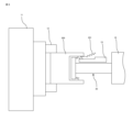
- FIG. 1 is a diagram showing an example of an NC lathe machine equipped with a fluid ejection device according to this embodiment.
- FIG. 2 is a side view showing the fluid ejecting head of the fluid ejecting apparatus according to this embodiment.
- FIG. 3 is a perspective view of the fluid-jet head of FIG. 2 as seen obliquely from the rear.
- 4 is an exploded perspective view of the fluid ejecting head of FIG. 2.
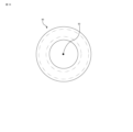
- FIG. 5 is a plan view showing the diffusion plate of FIG. 4.
- FIG. 6 is a cut end view of AA' of FIG. 5.
- FIG. FIG. 7 is an enlarged vertical cross-sectional view of the tip portion of the fluid ejecting head showing the direction of the fluid flowing inside the fluid ejecting head of FIG.
- FIG. 1 is a diagram showing an example of an NC lathe machine equipped with a fluid ejection device according to this embodiment.
- FIG. 2 is a side view showing the fluid ejecting head of the fluid ejecting
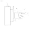
- FIG. 8 is a side view showing a state in which the fluid ejection device according to this embodiment is used.
- FIG. 9 is a plan view showing a first modification of the diffusion plate of FIG. 4.
- FIG. 10 is a plan view showing a second modification of the diffusion plate of FIG. 4.
- FIG. 11 is a diagram showing positional changes in the flow rate of the fluid ejected from the outer peripheral edge of the head portion and temporal changes at specific positions when the diffusion plates of FIGS. 5, 9 and 10 are used.
- FIG. 12 is a diagram showing a conventional example.
- a fluid ejecting apparatus 20 includes a fluid ejecting head 21 for ejecting chips generated during inner diameter machining of a work by means of a fluid, and a fluid ejecting head 21 for compressing fluid supplied from the outside.
- a compressor 23 that supplies fluid to the fluid ejecting head 21 and a controller 25 that controls the compressor 23 to change the flow rate or velocity of the fluid supplied from the compressor 23 to the fluid ejecting head 21 are provided.
- air or cutting fluid can be used as the fluid.
- the fluid injection device 20 is installed in, for example, an NC lathe processing machine 1 that can process the inner diameter of a work.
- a stage 16 movable in the Z direction is provided at a position facing a main shaft 11 of an NC lathe machine 1 having a chuck 12 for fixing a work, at a predetermined interval.
- the fluid jet head 21 is installed on the stage 16 .
- the fluid ejecting head 21 has an appearance like a circular tube with an outward flange at its tip, and is fixed to the stage 16 so that the center line of the circular tube is parallel to the Z-axis.
- tool rests 14 and 15 accommodate a plurality of tools 19 for cutting a work.
- the tool rests 14 and 15 are movable along two or three orthogonal axes in the X and Z directions.
- the fluid ejecting head 21 includes a shaft portion 30 having a flow path for fluid therein, and one end (tip) of the shaft portion 30 for ejecting the fluid supplied from the shaft portion 30 . and a disk-shaped head portion 40 that inclines from the outer peripheral edge to the center line CL of the shaft portion 30 and jets in a direction toward the other end (rear end) of the shaft portion 30 .
- the direction toward one end side (front end side) of the shaft portion 30 is appropriately used as the front side
- the direction toward the other end side (rear end side) of the shaft portion 30 is appropriately used as the rear side.
- the shaft portion 30 typically has a cylindrical shaft body 31 .
- the internal hollow of the shaft body 31 corresponds to the fluid flow path in the shaft portion 30 .
- the rear end of the shaft body 31 is provided with an introduction port 33 for introducing fluid inside.
- the head portion 40 has a disk-shaped bottom plate 50 , a disk-shaped diffusion plate 60 , and a disk-shaped cover 90 that covers the diffusion plate 60 .
- the bottom plate 50 , diffusion plate 60 , and cover 90 are arranged in order from the rear so that their center positions coincide with the center line CL of the shaft portion 30 .
- the bottom plate 50 is formed integrally with the tip of the shaft body 31 .
- the diffusion plate 60 is arranged with a predetermined distance from the bottom plate 50 .
- the resulting gap between the diffuser plate 60 and the bottom plate 50 corresponds to the fluid flow path in the head portion 40 .
- the diffuser plate 60 is configured to be slightly larger than the bottom plate 50 .
- the resulting circular gap between the outer peripheral edge of the diffusion plate 60 and the outer peripheral edge of the bottom plate 50 constitutes the discharge port 45 provided in the head portion 40 .
- the outlet 45 is open rearward.
- a plurality of partition plates 61 are radially arranged on the surface of the diffuser plate 60 to reach the outer peripheral edge thereof, so that the annular ejection port 45 is radially partitioned by the partition plates 61 . ing.
- a plurality of holes 55 are formed for communicating the flow path of the shaft portion 30 and the flow path of the head portion 40.
- the plurality of outlets 55 are arranged at regular intervals along the circumferential direction.
- a cylindrical partition block 54 projecting forward is integrally formed in the center of the bottom plate 50 .
- the outer peripheral surface of the partition block 54 is formed with a groove having a semicircular cross section along the front-rear direction so as not to block the outlet 55 .
- a columnar screw hole block 51 having a diameter smaller than that of the partition block 54 is integrally formed at the center of the tip end face of the partition block 54 .
- a groove (not shown) is cut in the outer peripheral surface of the screw hole block 51 along the circumferential direction, and an O-ring 52 is fitted in the groove.
- the outer peripheral surface of the screw hole block 51 and the inner peripheral surface of the cover 90 can be brought into close contact with each other by the O-ring 52, and the fluid leaks from the gap between the outer peripheral surface of the screw hole block 51 and the inner peripheral surface of the cover 90. can be prevented.
- a screw hole 53 for receiving the bolt 110 is formed in the tip surface of the screw hole block 51 .
- the diffusion plate 60 is fixed together with the cover 90 to the bottom plate 50 (that is, the shaft portion 30 with which the bottom plate 50 is integrally formed) by the bolts 110 and the screw holes 53 .
- a washer 100 is interposed between the bolt 110 and the cover 90 .
- a hole 63 for passing the partition block 54 provided on the bottom plate 50 is formed at the center position of the disk-shaped diffuser plate 60 , and a screw hole block 51 is inserted at the center position of the disk-shaped cover 90 .
- a hole is drilled for The holes formed in the diffuser plate 60 and the cover 90 are necessary for the fastening structure, and are unnecessary if, for example, the entire head section 40 is integrally constructed.
- the diffuser plate 60 is configured in an annular shape, but in an assembled state it forms a disk shape together with the partition block 54 .
- the diffusion plate 60 not only has the function of flowing the fluid supplied from the shaft portion 30 and blown forward along the center line CL from the outlet 55 of the bottom plate 50, but also the function of flowing the fluid in the direction orthogonal to the center line CL. It is configured to have a function of uniformly diffusing radially and a function of flowing backward the fluid that has reached the outer periphery.
- a plurality of partition plates 61 are provided on the surface of the diffuser plate 60 .
- the surface of the diffuser plate 60 refers to the surface facing the bottom plate 50 .
- the plurality of partition plates 61 are arranged at equal intervals along the circumferential direction. That is, the plurality of partition plates 61 are arranged radially.
- the partition plate 61 has the same height as the distance from the surface of the diffusion plate 60 to the surface of the bottom plate 50 .
- the partition plate 61 has a length from the inner peripheral edge (the outer peripheral surface of the screw hole block 51) to the outer peripheral edge.
- the thickness of the partition plate 61 near the outer peripheral edge is formed to be thinner than the thickness of the central portion.
- a space between the diffusion plate 60 and the bottom plate 50 is radially partitioned by a partition block 54 provided in the center of the surface of the bottom plate 50 and a plurality of partition plates 61 radially provided on the surface of the diffusion plate 60 . That is, the plurality of partition plates 61 and the partition blocks 54 can form a plurality of channels that expand in a tapered shape along the radial direction. Each channel is provided with one outlet 55 . Since the plurality of outlets 55 are arranged at equal intervals on a circle centered on the center line CL of the shaft portion 30, the flow rate of the fluid blown out from the outlets 55 is substantially the same. Since the supplied fluid flows only in the radial direction and does not flow in the circumferential direction, the diffusion plate 60 can radially and uniformly diffuse the fluid supplied from the shaft portion 30 .
- the diffuser plate 60 has a surface that undulates along the radial direction.
- the ridges and troughs of the undulations on the surface of the diffuser plate 60 are arranged concentrically.
- the fluid radially diffused by the diffuser plate 60 is pressurized at the positions of the corrugated crests where the gap between the diffuser plate 60 and the bottom plate 50 narrows, and the gap between the diffuser plate 60 and the bottom plate 50 widens. The pressure is reduced at the troughs of the corrugations.
- the fluid radially diffused by the diffuser plate 60 is pressurized and decompressed along the surface of the diffuser plate 60 . are rectified and reach the outer edge.
- the shape of the surface of the diffuser plate 60 also contributes to uniformly diffusing the fluid radially.
- the wavy surface of the diffuser plate 60 is undulating along the radial direction and is formed into peaks at the outer peripheral edge of the diffuser plate 60 .
- the fluid that has reached the outer peripheral edge of the diffuser plate 60 can be discharged rearward from the discharge ports 45 that are open rearward in a direction inclined to the center line.
- the corrugations formed on the surface of the diffuser plate 60 cause the channels near the outer periphery of the diffuser plate 60 (the gap between the bottom plate 50 and the diffuser plate 60 ) to shift to the channels near the center of the diffuser plate 60 (the bottom plate 50 ). and the diffusion plate 60).
- the pressure of the fluid jetted from the discharge port 45 can be increased, and chips generated during inner diameter machining of the workpiece can be vigorously discharged.
- the head portion 40 can be composed of roughly three plate-like parts, the bottom plate 50, the diffusion plate 60, and the cover 90, and the head portion 40 can be made thin.
- the head portion 40 is prevented from interfering with the cutting edge of the cutting tool during inner diameter machining of a workpiece, and can be used for inner diameter machining of various workpieces.
- the fluid can be ejected as follows. That is, as shown in FIG. 7, the fluid introduced into the shaft portion 30 flows forward inside the shaft portion 30 and is blown forward along the center line CL from the outlet 55 formed in the bottom plate 50. . Fluid blown forward along the center line CL from the outlet 55 of the bottom plate 50 is radially diffused by the diffusion plate 60 in a direction orthogonal to the center line CL. The fluid diffused by the diffuser plate 60 passes through the gap between the diffuser plate 60 and the bottom plate 50 and flows rearward along the center line CL from the discharge ports 45 opened rearward in the outer peripheral edge of the head portion 40 . It can be discharged in an inclined direction. That is, the fluid introduced into the inside from behind the shaft portion 30 flows forward inside the shaft portion 30 , is folded back at the head portion 40 , and is jetted rearward from the outer peripheral edge of the head portion 40 .
- the fluid ejection head 21 is configured in a shape in which a disk-shaped head portion 40 is provided at the tip of a rod-shaped shaft portion 30, so that the fluid can be easily applied to the hole of the workpiece 200 without obstructing the movement of the tool or the like.
- An injection head 21 can be inserted.
- the disk-shaped head portion 40 at the tip of the fluid jet head 21 is inserted into the hollow of the workpiece 200, and furthermore, the cutting edge of the cutting tool 19 for inner diameter machining is inserted. It is moved by the stage 16 so as to be placed at a deep position.
- the fluid injection device 20 functions as an air seal device, and can prevent chips 201 generated during inner diameter machining of the work 200 from entering the interior of the work 200 .
- the fluid ejection device is a non-contact device that ejects a compressed fluid, manual sealing work and sensory inspection are not required, and unmanned production of workpieces that require inner diameter machining can be realized.
- the surface of the diffuser plate 60 is formed into a corrugated shape that undulates along the radial direction, and a plurality of partition plates 61 are provided radially on the surface of the diffuser plate 60 .
- the flow rate of the fluid ejected from the outer peripheral edge of the head portion 40 can be made uniform over the entire circumference, and the change in the flow rate over time at a specific angular position can be reduced. Chips generated during inner diameter machining of the work can be stably discharged over the entire circumference of the inner diameter of the work.
- the configuration of the diffusion plate 60 is not limited to this embodiment.
- the plurality of partition plates 71 radially provided on the surface of the diffuser plate 70 may not extend to the outer peripheral edge of the diffuser plate 70 .
- the diffuser plate 70 shown in FIG. 9 is used, for example, as shown in FIG. It is larger than when it is used, and the time variation of the fluid flow rate at a particular angular position of the outer peripheral edge is also large. However, the use of such diffusion plate 70 is not completely denied.
- diffusion plate 80 may not have a partition plate.
- the diffusion plate 80 shown in FIG. 10 is used, for example, as shown in FIG.
- the time change of the flow rate of the fluid is large and random as compared with the case of using the diffuser plates 60 and 70 shown in FIGS.
- the use of such a diffusion plate 80 is not completely denied.
- the diffusion plate 80 shown in FIG. 10 has a simple shape, it may be superior to the diffusion plate 60 shown in FIG. 5 in terms of thinning the head section 40 and manufacturing cost.
- the surface of the diffusion plate 60 is corrugated. It may also be a simple disk without the partition plate 61 .
- the diffuser plate 60 and the like are configured based on the design concept that the fluid ejected from the outer peripheral edge of the head portion 40 is uniform over the entire circumference and does not change with time.
- the intensity of the fluid ejection can be varied, thereby effectively removing chips generated during inner diameter machining of the work from the inside of the work. There is a possibility that it can be discharged to the outside.
- the time change of the fluid flow rate can be realized by controlling the compressor 23 by the control device 25 .
- the fluid By changing the flow rate of the fluid ejected from the outer peripheral edge of the head portion 40 at each position on the outer peripheral edge, the fluid can be ejected in a vortex or the like from the entire head portion 40, thereby reducing cutting that occurs during inner diameter machining of the work.
- the powder can be effectively discharged from the inside of the workpiece to the outside.
- diffuser plates 70 and 80 in which the flow rate of the fluid changes depending on the position of the outer peripheral edge of the head portion 40, as shown in FIGS.
- the head portion 40 does not rotate with respect to the work in this embodiment, it may be configured so that the head portion 40 rotates with respect to the work.
- the head portion 40 is provided rotatably with respect to the shaft portion 30 by a bearing or the like, and the rotation of the head portion 40 is driven by a motor incorporated in the shaft portion 30 or the head portion 40, so that the head portion 40 is moved to the shaft portion. 30 can be rotated.
- the stage 16 or part of the stage 16 on which the fluid ejection head 21 is installed in the NC lathe machine 1 may be configured to be rotatable around the center line CL (the Z axis in FIG. 1) of the shaft portion 30. .
- the head portion 40 is formed in a disk shape so as to match the hollow cross-sectional shape of the work, but the shape of the head portion 40 is not limited to a disk shape.
- the head portion 40 may be square.
- the head section 40 or the fluid ejection head 21 is configured to be rotatable in synchronization with the rotation of the workpiece.
- the diffuser plate 60 has a structure for radially and uniformly flowing the fluid, but the bottom plate 50 may have that structure.
- the surface of the bottom plate 50 is formed in a corrugated shape that undulates along the radial direction, and a plurality of partition plates 61 are radially provided on the surface of the bottom plate 50 .
- the structure for uniformly flowing the fluid radially may be dispersed in the bottom plate 50 and the diffuser plate 60 .
- the diffusion plate 60 has a corrugated surface, and a plurality of partition plates 61 are radially provided on the surface of the bottom plate 50 .
- the diffuser plate 60 is made slightly larger than the bottom plate 50 to create a gap between the outer peripheral edge of the bottom plate 50 and the outer peripheral edge of the diffuser plate 60, and this gap is opened rearward.
- the discharge port 45 was able to do so.
- the configuration of the discharge port 45 is not limited to this embodiment, as long as the fluid diffused radially in the direction orthogonal to the center line CL by the diffuser plate 60 can be jetted rearward from the outer peripheral edge.
- the bottom plate 50 and the diffusion plate 60 are integrally formed like a box, and an annular slit is formed along the concentric circles of the bottom plate 50 at a position close to the outer peripheral edge of the bottom plate 50, and this slit is the discharge port. 45 may be used.
Landscapes
- Engineering & Computer Science (AREA)
- Mechanical Engineering (AREA)
- Auxiliary Devices For Machine Tools (AREA)
Abstract
Description
Claims (8)
- ワークの内径加工時に発生する切粉を流体により排出するための流体噴射ヘッドにおいて、
前記流体の流路を内部に備えた軸部と、
前記軸部の一端に設けられ、前記軸部から供給される前記流体を、前記軸部の中心線に傾斜し且つ前記軸部の他端に向かう方向に噴射する円盤形状のヘッド部と、
を具備する流体噴射ヘッド。 - 前記ヘッド部は、
前記軸部の一端に接続される円盤形状の底板と、
前記底板と対峙する位置に配置される円盤形状の拡散板と、を有し、
前記底板と前記拡散板との間に円環状の吐出口が形成される、請求項1記載の流体噴射ヘッド。 - 前記拡散板は、半径方向に沿って波形に起伏する表面を有する、請求項2記載の流体噴射ヘッド。
- 前記波形は、前記拡散板の外縁が前記波形の山となるように形成されている、請求項3記載の流体噴射ヘッド。
- 前記拡散板は、前記流体が放射状に拡散するのを補助するために円周方向に等間隔に配置された複数の仕切板を有する、請求項2乃至4のいずれか一項に記載の流体噴射ヘッド。
- 前記仕切板は、前記拡散板の外周縁まで設けられている、請求項5記載の流体噴射ヘッド。
- 前記仕切板は、前記拡散板の外周縁よりも内側の位置まで設けられている、請求項5記載の流体噴射ヘッド。
- 請求項1乃至請求項7のうちいずれか一項に記載の流体噴射ヘッドと、
前記流体を圧縮して前記流体噴射ヘッドに供給する流体供給装置と、
前記流体供給装置から前記流体噴射ヘッドに供給される前記流体の流量及び流速のうち少なくとも一方を変化させるために、前記流体供給装置を制御する制御装置と、
を具備する、流体噴射装置。
Priority Applications (4)
| Application Number | Priority Date | Filing Date | Title |
|---|---|---|---|
| CN202180103925.7A CN118176086A (zh) | 2021-11-26 | 2021-11-26 | 流体喷射头以及流体喷射装置 |
| JP2023563441A JP7712388B2 (ja) | 2021-11-26 | 2021-11-26 | 流体噴射ヘッド及び流体噴射装置 |
| DE112021008152.7T DE112021008152T5 (de) | 2021-11-26 | 2021-11-26 | Fluidstrahlkopf und Fluidstrahlvorrichtung |
| PCT/JP2021/043360 WO2023095280A1 (ja) | 2021-11-26 | 2021-11-26 | 流体噴射ヘッド及び流体噴射装置 |
Applications Claiming Priority (1)
| Application Number | Priority Date | Filing Date | Title |
|---|---|---|---|
| PCT/JP2021/043360 WO2023095280A1 (ja) | 2021-11-26 | 2021-11-26 | 流体噴射ヘッド及び流体噴射装置 |
Publications (1)
| Publication Number | Publication Date |
|---|---|
| WO2023095280A1 true WO2023095280A1 (ja) | 2023-06-01 |
Family
ID=86539253
Family Applications (1)
| Application Number | Title | Priority Date | Filing Date |
|---|---|---|---|
| PCT/JP2021/043360 Ceased WO2023095280A1 (ja) | 2021-11-26 | 2021-11-26 | 流体噴射ヘッド及び流体噴射装置 |
Country Status (4)
| Country | Link |
|---|---|
| JP (1) | JP7712388B2 (ja) |
| CN (1) | CN118176086A (ja) |
| DE (1) | DE112021008152T5 (ja) |
| WO (1) | WO2023095280A1 (ja) |
Citations (3)
| Publication number | Priority date | Publication date | Assignee | Title |
|---|---|---|---|---|
| JPS6452637U (ja) * | 1987-09-29 | 1989-03-31 | ||
| JPH0261510U (ja) * | 1988-10-21 | 1990-05-08 | ||
| JP2016159404A (ja) * | 2015-03-03 | 2016-09-05 | 富士機械製造株式会社 | ノズル付チャック装置 |
Family Cites Families (9)
| Publication number | Priority date | Publication date | Assignee | Title |
|---|---|---|---|---|
| AT212082B (de) * | 1958-03-25 | 1960-11-25 | Motorpal Jihlava Np | Einspritzdüse zur Kraftstoffeinspritzung in Verbrennungsmotoren |
| KR800000163Y1 (ko) * | 1979-03-30 | 1980-03-07 | 최진민 | 횡형 보일러 |
| JP2000210837A (ja) * | 1999-01-25 | 2000-08-02 | Yokogawa Kazuhiko | 圧縮した気体を使った加工点冷却加工用ノズル |
| JP3993090B2 (ja) * | 2002-12-27 | 2007-10-17 | 津田駒工業株式会社 | 水噴射式織機の緯入れノズル |
| JP4982253B2 (ja) * | 2007-05-30 | 2012-07-25 | アイシン・エィ・ダブリュ株式会社 | コンビネーションホルダ |
| JP6068924B2 (ja) * | 2012-10-23 | 2017-01-25 | 株式会社ショーワ | 切粉除去装置 |
| CN103317386A (zh) * | 2013-07-16 | 2013-09-25 | 沈阳第一机床厂 | 车床主轴中心喷射冷却装置 |
| JP6810113B2 (ja) * | 2018-09-07 | 2021-01-06 | ファナック株式会社 | 工作機械 |
| CN111774587B (zh) * | 2020-07-29 | 2021-07-23 | 厦门理工学院 | 一种自吸套料钻及使用方法 |
-
2021
- 2021-11-26 CN CN202180103925.7A patent/CN118176086A/zh active Pending
- 2021-11-26 WO PCT/JP2021/043360 patent/WO2023095280A1/ja not_active Ceased
- 2021-11-26 DE DE112021008152.7T patent/DE112021008152T5/de active Pending
- 2021-11-26 JP JP2023563441A patent/JP7712388B2/ja active Active
Patent Citations (3)
| Publication number | Priority date | Publication date | Assignee | Title |
|---|---|---|---|---|
| JPS6452637U (ja) * | 1987-09-29 | 1989-03-31 | ||
| JPH0261510U (ja) * | 1988-10-21 | 1990-05-08 | ||
| JP2016159404A (ja) * | 2015-03-03 | 2016-09-05 | 富士機械製造株式会社 | ノズル付チャック装置 |
Also Published As
| Publication number | Publication date |
|---|---|
| CN118176086A (zh) | 2024-06-11 |
| JP7712388B2 (ja) | 2025-07-23 |
| JPWO2023095280A1 (ja) | 2023-06-01 |
| DE112021008152T5 (de) | 2024-06-13 |
Similar Documents
| Publication | Publication Date | Title |
|---|---|---|
| JP6378976B2 (ja) | フランジ機構及び切削装置 | |
| US8393830B2 (en) | Cylindrical rotating tool with internal fluid passage and machining method using the same | |
| US4795292A (en) | Chuck for rotary metal cutting tool | |
| JP6526987B2 (ja) | スロットミーリングディスク及びこのようなスロットミーリングディスク用の回転可能な取付けシャフト | |
| CN101530971B (zh) | 具有转子喷射驱动用流体的主轴装置 | |
| EP0340026B1 (en) | Arbor for mounting a tool to a spindle of a machine tool and a machining method of employing the same | |
| TWI706826B (zh) | 工作機械用之旋轉工作台裝置 | |
| CN106623997B (zh) | 车床刀塔组件 | |
| JP6851703B1 (ja) | シャットオフノズル | |
| US10532416B2 (en) | Machining tool for deburring boreholes | |
| WO2023095280A1 (ja) | 流体噴射ヘッド及び流体噴射装置 | |
| TWI848049B (zh) | 噴嘴、噴射加工裝置及噴射加工方法 | |
| KR101593832B1 (ko) | 세정도구 | |
| WO2014091748A1 (ja) | 回転切削工具及び回転研削工具 | |
| CN112372150B (zh) | 一种可旋转的激光水射流集成头装置 | |
| US20240075573A1 (en) | Spray nozzle for lubricant and coolant fluid | |
| JPS5892475A (ja) | 静電塗装機 | |
| JP5028040B2 (ja) | フライス工具装置 | |
| JPH0639699A (ja) | 溝加工装置 | |
| JPH10235507A (ja) | 穴あけ加工方法及び穴あけ加工装置 | |
| JP6562788B2 (ja) | クーラント用ノズル | |
| JP2009137000A (ja) | ワイヤカット放電加工機とその加工液ノズル装置 | |
| JP4291680B2 (ja) | 穴加工装置 | |
| JPH06170683A (ja) | 切屑吸引式転削工具 | |
| JPH04111705A (ja) | 内周切削工具 |
Legal Events
| Date | Code | Title | Description |
|---|---|---|---|
| 121 | Ep: the epo has been informed by wipo that ep was designated in this application |
Ref document number: 21965652 Country of ref document: EP Kind code of ref document: A1 |
|
| ENP | Entry into the national phase |
Ref document number: 2023563441 Country of ref document: JP Kind code of ref document: A |
|
| WWE | Wipo information: entry into national phase |
Ref document number: 202180103925.7 Country of ref document: CN |
|
| 122 | Ep: pct application non-entry in european phase |
Ref document number: 21965652 Country of ref document: EP Kind code of ref document: A1 |