WO2023090464A2 - 両面テープ及びテープカッター - Google Patents
両面テープ及びテープカッター Download PDFInfo
- Publication number
- WO2023090464A2 WO2023090464A2 PCT/JP2023/012113 JP2023012113W WO2023090464A2 WO 2023090464 A2 WO2023090464 A2 WO 2023090464A2 JP 2023012113 W JP2023012113 W JP 2023012113W WO 2023090464 A2 WO2023090464 A2 WO 2023090464A2
- Authority
- WO
- WIPO (PCT)
- Prior art keywords
- tape
- double
- side plate
- tape cutter
- cutter
- Prior art date
- Legal status (The legal status is an assumption and is not a legal conclusion. Google has not performed a legal analysis and makes no representation as to the accuracy of the status listed.)
- Ceased
Links
Images









Classifications
-
- B—PERFORMING OPERATIONS; TRANSPORTING
- B65—CONVEYING; PACKING; STORING; HANDLING THIN OR FILAMENTARY MATERIAL
- B65H—HANDLING THIN OR FILAMENTARY MATERIAL, e.g. SHEETS, WEBS, CABLES
- B65H35/00—Delivering articles from cutting or line-perforating machines; Article or web delivery apparatus incorporating cutting or line-perforating devices, e.g. adhesive tape dispensers
- B65H35/0006—Article or web delivery apparatus incorporating cutting or line-perforating devices
-
- C—CHEMISTRY; METALLURGY
- C09—DYES; PAINTS; POLISHES; NATURAL RESINS; ADHESIVES; COMPOSITIONS NOT OTHERWISE PROVIDED FOR; APPLICATIONS OF MATERIALS NOT OTHERWISE PROVIDED FOR
- C09J—ADHESIVES; NON-MECHANICAL ASPECTS OF ADHESIVE PROCESSES IN GENERAL; ADHESIVE PROCESSES NOT PROVIDED FOR ELSEWHERE; USE OF MATERIALS AS ADHESIVES
- C09J7/00—Adhesives in the form of films or foils
- C09J7/30—Adhesives in the form of films or foils characterised by the adhesive composition
- C09J7/38—Pressure-sensitive adhesives [PSA]
-
- C—CHEMISTRY; METALLURGY
- C09—DYES; PAINTS; POLISHES; NATURAL RESINS; ADHESIVES; COMPOSITIONS NOT OTHERWISE PROVIDED FOR; APPLICATIONS OF MATERIALS NOT OTHERWISE PROVIDED FOR
- C09J—ADHESIVES; NON-MECHANICAL ASPECTS OF ADHESIVE PROCESSES IN GENERAL; ADHESIVE PROCESSES NOT PROVIDED FOR ELSEWHERE; USE OF MATERIALS AS ADHESIVES
- C09J7/00—Adhesives in the form of films or foils
- C09J7/40—Adhesives in the form of films or foils characterised by release liners
Definitions
- Patent Document 1 As a conventional double-sided tape, there is one described in Patent Document 1, for example.
- the double-faced tape described in the document is wound around an annular core. Both the front and back sides of the double-sided tape are adhesive surfaces. However, a release paper is attached to the surface of the double-sided tape. Therefore, the adhesive surface is exposed only on the back surface of the double-sided tape.
- This double-sided tape is used while being rotatably held by a tape cutter.
- the tape cutter has a pair of side plate portions (face plates), a bottom plate portion, and a cutting blade.
- the pair of side plate portions covers the double-sided tape from both sides.
- the bottom plate portion is connected to the lower ends of the side plate portions so as to connect the side plate portions.
- a cutting blade is provided at the end of the bottom plate portion.
- the present invention has been made in view of the above problems, and an object of the present invention is to provide a double-sided tape that contributes to reducing the amount of release paper discharged, and a tape cutter equipped with the same.
- a tape cutter according to the present invention is a tape cutter used for feeding and cutting the double-sided tape, and is characterized in that the double-sided tape is rotatably held.
- a double-sided tape that contributes to reducing the amount of release paper discharged and a tape cutter provided with the same are realized.
- FIG. 2 is a plan view showing a lead-out portion 1b of the double-sided tape of FIG. 1; It is a bottom view which shows the drawer part 1b of the double-sided tape of FIG.
- FIG. 3 is a cross-sectional view taken along line IV-IV of FIG. 2;
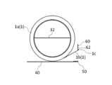
- 1 is a perspective view showing a first embodiment of a tape cutter according to the invention;
- FIG. Figure 6 is a side view of the tape cutter of Figure 5; 6 is a front view of the tape cutter of FIG. 5;
- FIG. Figure 6 is an end view of the tape cutter of Figure 5;
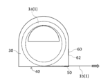
- FIG. 6 is a side view for explaining an example of how to use the tape cutter of FIG. 5;
- FIG. 1 is a perspective view showing a first embodiment of a tape cutter according to the invention
- FIG. Figure 6 is a side view of the tape cutter of Figure 5;
- 6 is a front view of the tape cutter of FIG. 5;
- FIG. Figure 6 is an end view of the tape cutter of Figure 5;
- FIG. 6 is a side view for explaining an example of how to use the tape cutter of FIG. 5;
- FIG. 6 is a side view for explaining an example of how to use the tape cutter of FIG. 5;
- FIG. 4 is a perspective view showing a second embodiment of a tape cutter according to the invention;
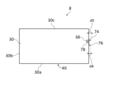
- Figure 13 is a side view of the tape cutter of Figure 12; 13 is a front view of the tape cutter of FIG. 12;
- FIG. FIG. 13 is a plan view showing the tape cutter of FIG. 12;
- Figure 13 is an end view of the tape cutter of Figure 12;
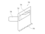
- 4 is a perspective view showing a guide portion 70;
- FIG. 13 is an end view for explaining an example of how to use the tape cutter of FIG. 12;
- FIG. 13 is an end view for explaining an example of how to use the tape cutter of FIG. 12;
- FIG. 10 is a plan view for explaining a modified example of the release paper 20;
- FIG. 11 is a plan view for explaining another modified example of the release paper 20;
- FIG. 1 is a side view showing one embodiment of the double-sided tape according to the present invention.
- the double-sided tape 1 is wound around an annular core 90 .
- the double-sided tape 1 consists of a winding portion 1a and a lead-out portion 1b.
- the wound portion 1a is a portion of the double-sided tape 1 wound around the core 90, and has an annular shape as a whole.
- the pull-out portion 1b is a portion of the double-sided tape 1 pulled out from the winding portion 1a.
- the double-sided tape 1 has a tape body 10 and a release paper 20 .
- the tape body 10 has a front surface 12 (first surface) and a back surface 14 (second surface). Both the front surface 12 and the back surface 14 are adhesive surfaces. In this embodiment, the entire front surface 12 is an adhesive surface, and the entire back surface 14 is also an adhesive surface.
- the release paper 20 is attached to the surface 12 of the tape body 10 .
- Release paper 20 is applied to only a portion of surface 12 . That is, the release paper 20 is attached only to a part of the adhesive surface of the surface 12 .
- the release paper 20 is attached only to a portion of the surface 12 in the width direction of the tape body 10 (vertical direction in FIGS. 2 and 3).
- the width direction of the tape body 10 is a direction perpendicular to the extending direction of the tape body 10 (horizontal direction in FIGS. 2 and 3). Therefore, the width w1 of the release paper 20 is smaller than the width w2 of the tape body .
- the width w1 is preferably 20% or more and 50% or less of the width w2.
- the center line C1 of the release paper 20 coincides with the center line C2 of the tape body 10.
- the center line C1 and the center line C2 are imaginary straight lines that bisect the release paper 20 and the tape body 10 in the width direction, respectively.
- the release paper 20 is continuously attached to the surface 12 in the extending direction of the tape body 10 . That is, the release paper 20 is attached to the entire surface 12 in the extending direction of the tape body 10 .
- the tape cutter 6 is used to pay out and cut the double-sided tape 1 .
- the double-sided tape 1 is rotatably held by the tape cutter 6 . 5 to 7, illustration of the double-sided tape 1 is omitted.
- the tape cutter 6 includes a pair of side plate portions 30 , a bottom plate portion 40 , a cutting blade 50 and an adhering portion 60 .
- a pair of side plate portions 30 covers the double-sided tape 1 from both sides.
- FIG. 8 shows an end surface that is parallel to the side plate portions 30 and positioned between the pair of side plate portions 30 .
- a lower portion of each side plate portion 30 (in a side view, a portion below a straight line including an insertion portion 32 described later) is rectangular.
- the upper portion of each side plate portion 30 (the portion above the straight line in side view) has a semicircular shape.
- the side plate portion 30 may cover the entire double-sided tape 1 from the side, or may cover only a portion thereof.
- the side plate portion 30 may overlap the entire double-sided tape 1 or may overlap only a portion of the double-sided tape 1 when viewed from the side.
- Each side plate portion 30 has a plate shape.
- a material for the side plate portion 30 for example, paper, plastic, metal, or wood can be used. Papers also include processed papers and cellulose nanofibers (CNF).
- the plastic may be a biodegradable plastic.
- An insertion portion 32 is connected to each side plate portion 30 .
- the insertion part 32 is inserted inside the core 90 of the double-sided tape 1 so that the double-sided tape 1 does not come off the tape cutter 6 .
- the insertion portion 32 has a plate shape.
- the thickness direction of the insertion portion 32 is perpendicular to the thickness direction of the side plate portion 30 .
- the two insertion portions 32 are fixed to each other in an overlapping state. Thereby, the center portions of the pair of side plate portions 30 are connected by the insertion portion 32 .
- the “central portion” is a portion of the side plate portion 30 other than the peripheral edge.
- Each insertion portion 32 is preferably formed integrally with the side plate portion 30 .
- the bottom plate portion 40 is connected to the lower end 30 a of each side plate portion 30 . Thereby, the lower ends 30 a of the pair of side plate portions 30 are connected by the bottom plate portion 40 .
- the bottom plate portion 40 may be connected to the entire lower end 30a of each side plate portion 30, or may be connected to only a portion thereof.
- the bottom plate portion 40 has a plate shape.
- the thickness direction of the bottom plate portion 40 is perpendicular to the thickness direction of the side plate portion 30 and equal to the thickness direction of the insertion portion 32 .
- the bottom plate portion 40 is preferably formed integrally with the side plate portion 30 .
- the material of the bottom plate portion 40 may be the same as or different from that of the side plate portion 30 .
- the cutting blade 50 is provided at the end of the bottom plate portion 40 .
- the cutting blade 50 is fixed on the bottom plate portion 40 .
- the cutting blade 50 cuts the double-sided tape 1 while in contact with the front surface 12 side (the release paper 20 ) of the tape body 10 .
- the tip of the cutting blade 50 protrudes from the bottom plate portion 40 .
- the tip of the cutting blade 50 is separated from the winding portion 1a.
- the cutting blade 50 cuts the double-sided tape 1 leaving a fixed length of the drawn-out portion 1b.
- the material of the cutting blade 50 may be the same as or different from the material of the side plate portion 30 .
- the cutting blade 50 may be formed integrally with the bottom plate portion 40 .
- the sticking part 60 is provided above the cutting blade 50 .
- the back surface 14 of the tape body 10 is attached to the attaching portion 60 with the end 1 c of the double-sided tape 1 (the lead-out portion 1 b ) floating from the cutting blade 50 .
- the rear surface 14 is attached to the tip portion 62 of the attachment portion 60 .
- the tip portion 62 is equal to the lower end of the sticking portion 60 .
- the tip portion 62 (the portion with which the back surface 14 contacts) may be flat or uneven.
- the width of the adhering portion 60 monotonously decreases toward the tip portion 62 .
- the width w3 (see FIG. 7) of the tip portion 62 is smaller than the width w2 of the tape body 10. As shown in FIG.
- the width w3 is preferably 50% or less of the width w2, more preferably 20% or less.
- the sticking portion 60 is connected to each side plate portion 30 .
- the sticking portion 60 is connected to the side end 30 b of each side plate portion 30 .
- the side end 30b is a portion of the peripheral edge of the side plate portion 30 other than the lower end 30a located at the lower portion.
- the side end 30b is linear.
- the side ends 30b of the pair of side plate portions 30 are connected by the sticking portion 60.
- the side ends 30b of the pair of side plate portions 30 are connected to each other only by the sticking portion 60.
- the side ends 30b of the pair of side plate portions 30 are not connected to each other on the opposite side of the sticking portion 60.
- the distance d1 (see FIG. 7) from the cutting blade 50 to the sticking portion 60 (tip portion 62) in the vertical direction is preferably equal to or greater than the interval d2 between the pair of side plate portions 30.
- the vertical direction is equal to the thickness direction of the bottom plate portion 40 (the vertical direction in FIGS. 5 to 7).
- the distance d1 is preferably 10 mm or more, more preferably 15 mm or more.
- the sticking portion 60 may be detachable with respect to the pair of side plate portions 30, or may not be detachable.
- detachable means that attachment and detachment of the sticking portion 60 to the side plate portion 30 can be repeated without damaging the side plate portion 30 and the sticking portion 60 .
- the tip portion 62 is located on the side end 30b of the side plate portion 30 when viewed from the side. In plan view, the tip portion 62 may or may not overlap the tip of the cutting blade 50 . That is, the tip portion 62 may be positioned directly above the tip of the cutting blade 50 or may be positioned obliquely above it. In the latter case, the distance (horizontal distance) from the tip of the cutting blade 50 to the tip 62 in plan view is preferably smaller than the distance d1.
- the sticking portion 60 has a plate shape.
- the thickness direction of the sticking portion 60 is perpendicular to both the thickness direction of the side plate portion 30 and the thickness direction of the bottom plate portion 40 .
- the thickness of the sticking portion 60 is preferably equal to the thickness of each side plate portion 30 .
- the sticking portion 60 may be formed integrally with the side plate portion 30 .
- the material of the sticking portion 60 may be the same as or different from the material of the side plate portion 30 .
- the double-sided tape 1 (drawer portion 1 b ) is pinched with fingers to peel off the double-sided tape 1 from the sticking portion 60 and then pulled along the bottom plate portion 40 .
- the double-faced tape 1 is fed out from between the bottom plate portion 40 and the sticking portion 60 .
- the double-sided tape 1 is cut by pressing the surface 12 of the tape body 10 and the release paper 20 against the tip of the cutting blade 50 .
- the back surface 14 of the tape body 10 is adhered to the adhered portion 60 again.
- the end 1c of the double-sided tape 1 protrudes from the tip portion 62.
- the drawer portion 1b is adhered only to the adhered portion 60.
- the tape cutter 6 is configured so that the lead-out portion 1b is not adhered to a portion of the tape cutter 6 other than the adhered portion 60.
- the double-sided tape 1 can be fed out from the tape cutter 6 to obtain a cut piece of desired length.
- the double-sided tape 1 is provided with a tape body 10 in which both the front surface 12 and the back surface 14 are adhesive surfaces.
- a release paper 20 is attached to the surface 12 of the tape body 10 .
- Release paper 20 is applied to only a portion of surface 12 .
- the double-faced tape 1 and the tape cutter 6 including the double-sided tape 1 that contribute to reduction in the amount of release paper 20 discharged are realized.
- the distance d1 is preferably equal to or greater than the interval d2 between the pair of side plate portions 30. As shown in FIG. From the same point of view, the distance d1 is preferably 10 mm or more, more preferably 15 mm or more. On the other hand, if the distance d1 is too large, it may become difficult to secure a place in the tape cutter 6 for arranging the sticking portion 60 . From this point of view, the distance d1 is preferably 50 mm or less.
- the sticking portion 60 is connected to the side end 30b of each side plate portion 30. This makes it easier to align the tip portion 62 of the sticking portion 60 with the side edge 30 b of the side plate portion 30 .
- the tip portion 62 is located on the side end 30b of the side plate portion 30 in a side view. In this case, since the tip portion 62 does not enter the space sandwiched between the pair of side plate portions 30, it is advantageous in making it easier to pick up the double-faced tape 1 attached to the attaching portion 60 with fingers.
- the width w3 of the tip portion 62 is smaller than the width w2 of the tape body 10. In this case, by changing the width w3, it is possible to adjust the contact area between the tip portion 62 and the tape body 10, and thus the adhesive force between the sticking portion 60 and the tape body 10.
- FIG. This increases options for the material of the adhering portion 60, making it easier to integrally form the adhering portion 60 with other portions (the side plate portion 30, the bottom plate portion 40, and/or the cutting blade 50).
- the width w3 may be equal to the width w2 or may be greater than the width w2.
- the width w3 may be equal to the distance d2 between the pair of side plate portions 30. As shown in FIG.
- the thickness of the sticking portion 60 is equal to the thickness of each side plate portion 30, it becomes easier to form the side plate portion 30 and the sticking portion 60 from one sheet with a uniform thickness.
- the sticking portion 60 is made of the same material as the pair of side plate portions 30 and the bottom plate portion 40, the side plate portion 30, the bottom plate portion 40 and the sticking portion 60 can be easily formed integrally.
- the manufacturing process of the tape cutter 6 can be simplified, thereby reducing the manufacturing cost of the tape cutter 6.
- FIG. 12 corresponds to a view of the tape cutter of FIG. 12 viewed from the right side.
- 16 is an end view of the tape cutter of FIG. 12.
- the tape cutter 8 has a pair of side plate portions 30 , a bottom plate portion 40 and a guide portion 70 .
- a pair of side plate portions 30 covers the double-sided tape 1 from both sides.
- FIG. 16 shows an end surface parallel to the side plate portions 30 and located between the pair of side plate portions 30 .
- the side plate portion 30 covers only a portion of the winding portion 1a of the double-sided tape 1 from the side. That is, the side plate portion 30 overlaps only a portion of the winding portion 1a in a side view.
- Each side plate portion 30 has a rectangular plate shape.
- Each side plate portion 30 is formed with a notch 38 serving as an insertion port for a claw portion 78 to be described later.
- An insertion portion 32 is connected to each side plate portion 30 .
- the insertion part 32 is inserted inside the core 90 of the double-sided tape 1 so that the double-sided tape 1 does not come off the tape cutter 8 .
- the insertion portion 32 has a plate shape.
- the thickness direction of the insertion portion 32 is perpendicular to the thickness direction of the side plate portion 30 .
- the insertion portion 32 is connected to the upper end 30 c of each side plate portion 30 .
- the two insertion portions 32 are fixed to each other in an overlapping state. Thereby, the upper ends 30 c of the pair of side plate portions 30 are connected by the insertion portion 32 .
- Each insertion portion 32 is preferably formed integrally with the side plate portion 30 .
- the material of the insertion portion 32 may be the same as or different from the material of the side plate portion 30 .
- the bottom plate portion 40 is connected to the lower end 30 a of each side plate portion 30 . Thereby, the lower ends 30 a of the pair of side plate portions 30 are connected by the bottom plate portion 40 .
- the bottom plate portion 40 may be connected to the entire lower end 30a of each side plate portion 30, or may be connected to only a portion thereof.
- the bottom plate portion 40 has a plate shape.
- the thickness direction of the bottom plate portion 40 is perpendicular to the thickness direction of the side plate portion 30 and equal to the thickness direction of the insertion portion 32 .
- the bottom plate portion 40 is preferably formed integrally with the side plate portion 30 .
- the material of the bottom plate portion 40 may be the same as or different from that of the side plate portion 30 .
- the width w4 is defined as the horizontal dimension of the sticking surface 74a.
- the width w4 is preferably 50% or less of the width w2, more preferably 20% or less.
- the cutting blade 76 cuts the drawer portion 1b that has passed through the opening 72.
- the opening 72 and the sticking portion 74 described above are provided between the winding portion 1a and the cutting blade 76 along the drawn portion 1b.
- the tip of the cutting blade 76 is directed outward (away from the side end 30b) so as to easily cut the drawn-out portion 1b.
- the tip of the cutting blade 76 protrudes from the side end 30b of the side plate portion 30 in a side view.
- the tip of the cutting blade 76 is located inside the adhering portion 74 in a side view. That is, the distance d4 (see FIG.
- the material of the cutting blade 76 may be the same as or different from the material of the other portions of the guide portion 70. In the latter case, for example, it is conceivable to use metal as the material for the cutting blade 76 and paper as the material for the other parts. Moreover, the cutting blade 76 may be formed integrally with the other portion of the guide portion 70, or may be formed separately from the other portion and then attached to the portion.
- the double-sided tape 1 is provided with a tape body 10 in which both the front surface 12 and the back surface 14 are adhesive surfaces.
- a release paper 20 is attached to the surface 12 of the tape body 10 .
- Release paper 20 is applied to only a portion of surface 12 .
- the double-sided tape 1 and the tape cutter 8 having the double-sided tape 1 that contribute to the reduction of the amount of the release paper 20 discharged are realized.
- the width w4 of the sticking portion 74 is smaller than the width w2 of the tape body 10. In this case, by changing the width w4, it is possible to adjust the contact area between the sticking portion 74 and the lead portion 1b, and thus the adhesive force between the sticking portion 74 and the lead portion 1b. As a result, it is possible to increase the options for the material of the sticking portion 74 .
- the width w4 may be equal to the width w2 or may be larger than the width w2.
- the width w4 may be equal to the length d3 of the opening 72 in the horizontal direction.
- the opening 72 overlaps the side edge 30b of the side plate portion 30 in a side view.
- the guide portion 70 is connected to the side end 30b of each side plate portion 30. This makes it easier to align the position of the opening 72 with the side edge 30 b of the side plate portion 30 .
- the present invention is not limited to the above embodiments, and various modifications are possible.
- the center line C1 of the release paper 20 coincides with the center line C2 of the tape body 10 is exemplified.
- the centerline C1 may be offset from the centerline C2, as shown in FIG. 20, for example.
- the case where the entire surface 12 of the tape body 10 is an adhesive surface is exemplified.
- only a portion of surface 12 may be an adhesive surface.
- only a portion of back surface 14 may be an adhesive surface.
- the release paper 20 is attached only to a portion of the adhesive surface of the surface 12 .
Landscapes
- Chemical & Material Sciences (AREA)
- Organic Chemistry (AREA)
- Adhesive Tape Dispensing Devices (AREA)
- Adhesive Tapes (AREA)
Priority Applications (2)
| Application Number | Priority Date | Filing Date | Title |
|---|---|---|---|
| PCT/JP2023/012113 WO2023090464A2 (ja) | 2023-03-27 | 2023-03-27 | 両面テープ及びテープカッター |
| JP2023519593A JP7604040B2 (ja) | 2023-03-27 | 2023-03-27 | 両面テープ及びテープカッター |
Applications Claiming Priority (1)
| Application Number | Priority Date | Filing Date | Title |
|---|---|---|---|
| PCT/JP2023/012113 WO2023090464A2 (ja) | 2023-03-27 | 2023-03-27 | 両面テープ及びテープカッター |
Publications (2)
| Publication Number | Publication Date |
|---|---|
| WO2023090464A2 true WO2023090464A2 (ja) | 2023-05-25 |
| WO2023090464A3 WO2023090464A3 (ja) | 2023-07-27 |
Family
ID=86397088
Family Applications (1)
| Application Number | Title | Priority Date | Filing Date |
|---|---|---|---|
| PCT/JP2023/012113 Ceased WO2023090464A2 (ja) | 2023-03-27 | 2023-03-27 | 両面テープ及びテープカッター |
Country Status (2)
| Country | Link |
|---|---|
| JP (1) | JP7604040B2 (https=) |
| WO (1) | WO2023090464A2 (https=) |
Cited By (1)
| Publication number | Priority date | Publication date | Assignee | Title |
|---|---|---|---|---|
| JPWO2023163238A1 (https=) * | 2023-06-26 | 2023-08-31 |
Family Cites Families (9)
| Publication number | Priority date | Publication date | Assignee | Title |
|---|---|---|---|---|
| JPS6183275A (ja) * | 1984-10-01 | 1986-04-26 | Kimurashin Kk | 両面接着テ−プの製造方法 |
| JPS62124177A (ja) * | 1985-11-22 | 1987-06-05 | Yoshikazu Kimura | 接着テ−プ |
| JPH05320591A (ja) * | 1992-05-15 | 1993-12-03 | Nishi Shoji Kk | 変形両面粘着テープ及びその製法 |
| JPH0948553A (ja) * | 1995-08-07 | 1997-02-18 | Nichiban Co Ltd | 容器入巻テ−プ |
| JP4736154B2 (ja) * | 1999-12-27 | 2011-07-27 | 大日本印刷株式会社 | 両面接着テープ |
| JP2003020161A (ja) * | 2001-07-10 | 2003-01-21 | Nichiban Co Ltd | 粘着テ−プ容器 |
| JP2005320047A (ja) * | 2004-05-11 | 2005-11-17 | Kawaguchi Kk | 積層テープの繰り出し包装構造 |
| CN208308058U (zh) * | 2018-04-05 | 2019-01-01 | 深圳市骏业胶粘带科技有限公司 | 一种胶带切割机 |
| JP7341802B2 (ja) * | 2019-09-05 | 2023-09-11 | ニチバン株式会社 | テープカッター |
-
2023
- 2023-03-27 JP JP2023519593A patent/JP7604040B2/ja active Active
- 2023-03-27 WO PCT/JP2023/012113 patent/WO2023090464A2/ja not_active Ceased
Cited By (2)
| Publication number | Priority date | Publication date | Assignee | Title |
|---|---|---|---|---|
| JPWO2023163238A1 (https=) * | 2023-06-26 | 2023-08-31 | ||
| WO2023163238A3 (ja) * | 2023-06-26 | 2023-10-19 | 株式会社無有 | 粘着テープ |
Also Published As
| Publication number | Publication date |
|---|---|
| JP7604040B2 (ja) | 2024-12-23 |
| JPWO2023090464A1 (https=) | 2023-05-25 |
| WO2023090464A3 (ja) | 2023-07-27 |
Similar Documents
| Publication | Publication Date | Title |
|---|---|---|
| WO2023090464A2 (ja) | 両面テープ及びテープカッター | |
| TW201730018A (zh) | 塗膜轉印具 | |
| JP2528265B2 (ja) | キャリヤテ―プから基体にフィルムを転着するための手持ち式器具に用いられる交換カセット | |
| JP4099518B1 (ja) | テープディスペンサ | |
| JP7350410B2 (ja) | テープカッター | |
| US20030136522A1 (en) | Hand-held tape dispenser with tape positioning structure | |
| US20110114689A1 (en) | Parallelepiped tape cutter | |
| JP2014019483A (ja) | 巻回体収容箱及び巻回体入り収容箱 | |
| JP2681769B2 (ja) | カッター付きテープホルダー | |
| JP7473929B2 (ja) | テープカッター | |
| JP7506954B2 (ja) | 粘着テープ | |
| JP7412831B2 (ja) | テープカッター | |
| JP4281022B1 (ja) | ラップフィルムロール収納ケース | |
| JP7519729B2 (ja) | 粘着テープ | |
| CN212516408U (zh) | 一种用于拆卸液晶显示器保护屏的拉胶装置 | |
| JP4461675B2 (ja) | 転写具の転写ヘッド部構造および転写具 | |
| CN219117372U (zh) | 一种没有轻离型膜的单导铜箔胶带 | |
| US20250120797A1 (en) | Box assembly | |
| KR101539443B1 (ko) | 테이프 분리장치 | |
| CN221262625U (zh) | 电池和电子产品 | |
| US20250120796A1 (en) | Box assembly | |
| KR102814426B1 (ko) | 테이프 커터기 | |
| CN220034373U (zh) | 一种卷式易撕贴签胶带 | |
| KR200416054Y1 (ko) | 티슈박스 | |
| JP2998021B2 (ja) | 粘着テープカッター |
Legal Events
| Date | Code | Title | Description |
|---|---|---|---|
| ENP | Entry into the national phase |
Ref document number: 2023519593 Country of ref document: JP Kind code of ref document: A |
|
| 121 | Ep: the epo has been informed by wipo that ep was designated in this application |
Ref document number: 23725080 Country of ref document: EP Kind code of ref document: A2 |
|
| NENP | Non-entry into the national phase |
Ref country code: DE |
|
| 122 | Ep: pct application non-entry in european phase |
Ref document number: 23725080 Country of ref document: EP Kind code of ref document: A2 |