WO2023090133A1 - 合わせガラス及び液晶装置 - Google Patents
合わせガラス及び液晶装置 Download PDFInfo
- Publication number
- WO2023090133A1 WO2023090133A1 PCT/JP2022/040615 JP2022040615W WO2023090133A1 WO 2023090133 A1 WO2023090133 A1 WO 2023090133A1 JP 2022040615 W JP2022040615 W JP 2022040615W WO 2023090133 A1 WO2023090133 A1 WO 2023090133A1
- Authority
- WO
- WIPO (PCT)
- Prior art keywords
- liquid crystal
- covering member
- laminated glass
- light control
- transparent substrate
- Prior art date
- Legal status (The legal status is an assumption and is not a legal conclusion. Google has not performed a legal analysis and makes no representation as to the accuracy of the status listed.)
- Ceased
Links
Images


Classifications
-
- B—PERFORMING OPERATIONS; TRANSPORTING
- B32—LAYERED PRODUCTS
- B32B—LAYERED PRODUCTS, i.e. PRODUCTS BUILT-UP OF STRATA OF FLAT OR NON-FLAT, e.g. CELLULAR OR HONEYCOMB, FORM
- B32B3/00—Layered products comprising a layer with external or internal discontinuities or unevennesses, or a layer of non-planar shape; Layered products comprising a layer having particular features of form
- B32B3/02—Layered products comprising a layer with external or internal discontinuities or unevennesses, or a layer of non-planar shape; Layered products comprising a layer having particular features of form characterised by features of form at particular places, e.g. in edge regions
- B32B3/08—Layered products comprising a layer with external or internal discontinuities or unevennesses, or a layer of non-planar shape; Layered products comprising a layer having particular features of form characterised by features of form at particular places, e.g. in edge regions characterised by added members at particular parts
-
- G—PHYSICS
- G02—OPTICS
- G02F—OPTICAL DEVICES OR ARRANGEMENTS FOR THE CONTROL OF LIGHT BY MODIFICATION OF THE OPTICAL PROPERTIES OF THE MEDIA OF THE ELEMENTS INVOLVED THEREIN; NON-LINEAR OPTICS; FREQUENCY-CHANGING OF LIGHT; OPTICAL LOGIC ELEMENTS; OPTICAL ANALOGUE/DIGITAL CONVERTERS
- G02F1/00—Devices or arrangements for the control of the intensity, colour, phase, polarisation or direction of light arriving from an independent light source, e.g. switching, gating or modulating; Non-linear optics
- G02F1/01—Devices or arrangements for the control of the intensity, colour, phase, polarisation or direction of light arriving from an independent light source, e.g. switching, gating or modulating; Non-linear optics for the control of the intensity, phase, polarisation or colour
- G02F1/13—Devices or arrangements for the control of the intensity, colour, phase, polarisation or direction of light arriving from an independent light source, e.g. switching, gating or modulating; Non-linear optics for the control of the intensity, phase, polarisation or colour based on liquid crystals, e.g. single liquid crystal display cells
- G02F1/133—Constructional arrangements; Operation of liquid crystal cells; Circuit arrangements
- G02F1/1333—Constructional arrangements; Manufacturing methods
- G02F1/1335—Structural association of cells with optical devices, e.g. polarisers or reflectors
-
- B—PERFORMING OPERATIONS; TRANSPORTING
- B32—LAYERED PRODUCTS
- B32B—LAYERED PRODUCTS, i.e. PRODUCTS BUILT-UP OF STRATA OF FLAT OR NON-FLAT, e.g. CELLULAR OR HONEYCOMB, FORM
- B32B17/00—Layered products essentially comprising sheet glass, or glass, slag, or like fibres
- B32B17/06—Layered products essentially comprising sheet glass, or glass, slag, or like fibres comprising glass as the main or only constituent of a layer, next to another layer of a specific material
- B32B17/10—Layered products essentially comprising sheet glass, or glass, slag, or like fibres comprising glass as the main or only constituent of a layer, next to another layer of a specific material of synthetic resin
- B32B17/10005—Layered products essentially comprising sheet glass, or glass, slag, or like fibres comprising glass as the main or only constituent of a layer, next to another layer of a specific material of synthetic resin laminated safety glass or glazing
- B32B17/10165—Functional features of the laminated safety glass or glazing
- B32B17/10431—Specific parts for the modulation of light incorporated into the laminated safety glass or glazing
- B32B17/10467—Variable transmission
- B32B17/10495—Variable transmission optoelectronic, i.e. optical valve
- B32B17/10504—Liquid crystal layer
-
- B—PERFORMING OPERATIONS; TRANSPORTING
- B32—LAYERED PRODUCTS
- B32B—LAYERED PRODUCTS, i.e. PRODUCTS BUILT-UP OF STRATA OF FLAT OR NON-FLAT, e.g. CELLULAR OR HONEYCOMB, FORM
- B32B17/00—Layered products essentially comprising sheet glass, or glass, slag, or like fibres
- B32B17/06—Layered products essentially comprising sheet glass, or glass, slag, or like fibres comprising glass as the main or only constituent of a layer, next to another layer of a specific material
- B32B17/10—Layered products essentially comprising sheet glass, or glass, slag, or like fibres comprising glass as the main or only constituent of a layer, next to another layer of a specific material of synthetic resin
- B32B17/10005—Layered products essentially comprising sheet glass, or glass, slag, or like fibres comprising glass as the main or only constituent of a layer, next to another layer of a specific material of synthetic resin laminated safety glass or glazing
- B32B17/10009—Layered products essentially comprising sheet glass, or glass, slag, or like fibres comprising glass as the main or only constituent of a layer, next to another layer of a specific material of synthetic resin laminated safety glass or glazing characterized by the number, the constitution or treatment of glass sheets
- B32B17/10036—Layered products essentially comprising sheet glass, or glass, slag, or like fibres comprising glass as the main or only constituent of a layer, next to another layer of a specific material of synthetic resin laminated safety glass or glazing characterized by the number, the constitution or treatment of glass sheets comprising two outer glass sheets
-
- B—PERFORMING OPERATIONS; TRANSPORTING
- B32—LAYERED PRODUCTS
- B32B—LAYERED PRODUCTS, i.e. PRODUCTS BUILT-UP OF STRATA OF FLAT OR NON-FLAT, e.g. CELLULAR OR HONEYCOMB, FORM
- B32B17/00—Layered products essentially comprising sheet glass, or glass, slag, or like fibres
- B32B17/06—Layered products essentially comprising sheet glass, or glass, slag, or like fibres comprising glass as the main or only constituent of a layer, next to another layer of a specific material
- B32B17/10—Layered products essentially comprising sheet glass, or glass, slag, or like fibres comprising glass as the main or only constituent of a layer, next to another layer of a specific material of synthetic resin
- B32B17/10005—Layered products essentially comprising sheet glass, or glass, slag, or like fibres comprising glass as the main or only constituent of a layer, next to another layer of a specific material of synthetic resin laminated safety glass or glazing
- B32B17/10165—Functional features of the laminated safety glass or glazing
- B32B17/10174—Coatings of a metallic or dielectric material on a constituent layer of glass or polymer
- B32B17/10201—Dielectric coatings
- B32B17/10211—Doped dielectric layer, electrically conductive, e.g. SnO2:F
-
- B—PERFORMING OPERATIONS; TRANSPORTING
- B32—LAYERED PRODUCTS
- B32B—LAYERED PRODUCTS, i.e. PRODUCTS BUILT-UP OF STRATA OF FLAT OR NON-FLAT, e.g. CELLULAR OR HONEYCOMB, FORM
- B32B17/00—Layered products essentially comprising sheet glass, or glass, slag, or like fibres
- B32B17/06—Layered products essentially comprising sheet glass, or glass, slag, or like fibres comprising glass as the main or only constituent of a layer, next to another layer of a specific material
- B32B17/10—Layered products essentially comprising sheet glass, or glass, slag, or like fibres comprising glass as the main or only constituent of a layer, next to another layer of a specific material of synthetic resin
- B32B17/10005—Layered products essentially comprising sheet glass, or glass, slag, or like fibres comprising glass as the main or only constituent of a layer, next to another layer of a specific material of synthetic resin laminated safety glass or glazing
- B32B17/10165—Functional features of the laminated safety glass or glazing
- B32B17/10293—Edge features, e.g. inserts or holes
- B32B17/10302—Edge sealing
-
- B—PERFORMING OPERATIONS; TRANSPORTING
- B32—LAYERED PRODUCTS
- B32B—LAYERED PRODUCTS, i.e. PRODUCTS BUILT-UP OF STRATA OF FLAT OR NON-FLAT, e.g. CELLULAR OR HONEYCOMB, FORM
- B32B17/00—Layered products essentially comprising sheet glass, or glass, slag, or like fibres
- B32B17/06—Layered products essentially comprising sheet glass, or glass, slag, or like fibres comprising glass as the main or only constituent of a layer, next to another layer of a specific material
- B32B17/10—Layered products essentially comprising sheet glass, or glass, slag, or like fibres comprising glass as the main or only constituent of a layer, next to another layer of a specific material of synthetic resin
- B32B17/10005—Layered products essentially comprising sheet glass, or glass, slag, or like fibres comprising glass as the main or only constituent of a layer, next to another layer of a specific material of synthetic resin laminated safety glass or glazing
- B32B17/1055—Layered products essentially comprising sheet glass, or glass, slag, or like fibres comprising glass as the main or only constituent of a layer, next to another layer of a specific material of synthetic resin laminated safety glass or glazing characterized by the resin layer, i.e. interlayer
- B32B17/10697—Layered products essentially comprising sheet glass, or glass, slag, or like fibres comprising glass as the main or only constituent of a layer, next to another layer of a specific material of synthetic resin laminated safety glass or glazing characterized by the resin layer, i.e. interlayer being cross-linked
-
- B—PERFORMING OPERATIONS; TRANSPORTING
- B32—LAYERED PRODUCTS
- B32B—LAYERED PRODUCTS, i.e. PRODUCTS BUILT-UP OF STRATA OF FLAT OR NON-FLAT, e.g. CELLULAR OR HONEYCOMB, FORM
- B32B17/00—Layered products essentially comprising sheet glass, or glass, slag, or like fibres
- B32B17/06—Layered products essentially comprising sheet glass, or glass, slag, or like fibres comprising glass as the main or only constituent of a layer, next to another layer of a specific material
- B32B17/10—Layered products essentially comprising sheet glass, or glass, slag, or like fibres comprising glass as the main or only constituent of a layer, next to another layer of a specific material of synthetic resin
- B32B17/10005—Layered products essentially comprising sheet glass, or glass, slag, or like fibres comprising glass as the main or only constituent of a layer, next to another layer of a specific material of synthetic resin laminated safety glass or glazing
- B32B17/1055—Layered products essentially comprising sheet glass, or glass, slag, or like fibres comprising glass as the main or only constituent of a layer, next to another layer of a specific material of synthetic resin laminated safety glass or glazing characterized by the resin layer, i.e. interlayer
- B32B17/10706—Layered products essentially comprising sheet glass, or glass, slag, or like fibres comprising glass as the main or only constituent of a layer, next to another layer of a specific material of synthetic resin laminated safety glass or glazing characterized by the resin layer, i.e. interlayer being photo-polymerized
-
- B—PERFORMING OPERATIONS; TRANSPORTING
- B32—LAYERED PRODUCTS
- B32B—LAYERED PRODUCTS, i.e. PRODUCTS BUILT-UP OF STRATA OF FLAT OR NON-FLAT, e.g. CELLULAR OR HONEYCOMB, FORM
- B32B27/00—Layered products comprising a layer of synthetic resin
- B32B27/32—Layered products comprising a layer of synthetic resin comprising polyolefins
- B32B27/325—Layered products comprising a layer of synthetic resin comprising polyolefins comprising polycycloolefins
-
- B—PERFORMING OPERATIONS; TRANSPORTING
- B32—LAYERED PRODUCTS
- B32B—LAYERED PRODUCTS, i.e. PRODUCTS BUILT-UP OF STRATA OF FLAT OR NON-FLAT, e.g. CELLULAR OR HONEYCOMB, FORM
- B32B27/00—Layered products comprising a layer of synthetic resin
- B32B27/36—Layered products comprising a layer of synthetic resin comprising polyesters
- B32B27/365—Layered products comprising a layer of synthetic resin comprising polyesters comprising polycarbonates
-
- B—PERFORMING OPERATIONS; TRANSPORTING
- B32—LAYERED PRODUCTS
- B32B—LAYERED PRODUCTS, i.e. PRODUCTS BUILT-UP OF STRATA OF FLAT OR NON-FLAT, e.g. CELLULAR OR HONEYCOMB, FORM
- B32B3/00—Layered products comprising a layer with external or internal discontinuities or unevennesses, or a layer of non-planar shape; Layered products comprising a layer having particular features of form
- B32B3/02—Layered products comprising a layer with external or internal discontinuities or unevennesses, or a layer of non-planar shape; Layered products comprising a layer having particular features of form characterised by features of form at particular places, e.g. in edge regions
-
- B—PERFORMING OPERATIONS; TRANSPORTING
- B32—LAYERED PRODUCTS
- B32B—LAYERED PRODUCTS, i.e. PRODUCTS BUILT-UP OF STRATA OF FLAT OR NON-FLAT, e.g. CELLULAR OR HONEYCOMB, FORM
- B32B7/00—Layered products characterised by the relation between layers; Layered products characterised by the relative orientation of features between layers, or by the relative values of a measurable parameter between layers, i.e. products comprising layers having different physical, chemical or physicochemical properties; Layered products characterised by the interconnection of layers
- B32B7/02—Physical, chemical or physicochemical properties
- B32B7/023—Optical properties
-
- B—PERFORMING OPERATIONS; TRANSPORTING
- B32—LAYERED PRODUCTS
- B32B—LAYERED PRODUCTS, i.e. PRODUCTS BUILT-UP OF STRATA OF FLAT OR NON-FLAT, e.g. CELLULAR OR HONEYCOMB, FORM
- B32B7/00—Layered products characterised by the relation between layers; Layered products characterised by the relative orientation of features between layers, or by the relative values of a measurable parameter between layers, i.e. products comprising layers having different physical, chemical or physicochemical properties; Layered products characterised by the interconnection of layers
- B32B7/04—Interconnection of layers
- B32B7/12—Interconnection of layers using interposed adhesives or interposed materials with bonding properties
-
- B—PERFORMING OPERATIONS; TRANSPORTING
- B60—VEHICLES IN GENERAL
- B60J—WINDOWS, WINDSCREENS, NON-FIXED ROOFS, DOORS, OR SIMILAR DEVICES FOR VEHICLES; REMOVABLE EXTERNAL PROTECTIVE COVERINGS SPECIALLY ADAPTED FOR VEHICLES
- B60J3/00—Antiglare equipment associated with windows or windscreens; Sun visors for vehicles
- B60J3/04—Antiglare equipment associated with windows or windscreens; Sun visors for vehicles adjustable in transparency
-
- E—FIXED CONSTRUCTIONS
- E06—DOORS, WINDOWS, SHUTTERS, OR ROLLER BLINDS IN GENERAL; LADDERS
- E06B—FIXED OR MOVABLE CLOSURES FOR OPENINGS IN BUILDINGS, VEHICLES, FENCES OR LIKE ENCLOSURES IN GENERAL, e.g. DOORS, WINDOWS, BLINDS, GATES
- E06B9/00—Screening or protective devices for wall or similar openings, with or without operating or securing mechanisms; Closures of similar construction
- E06B9/24—Screens or other constructions affording protection against light, especially against sunshine; Similar screens for privacy or appearance; Slat blinds
-
- G—PHYSICS
- G02—OPTICS
- G02F—OPTICAL DEVICES OR ARRANGEMENTS FOR THE CONTROL OF LIGHT BY MODIFICATION OF THE OPTICAL PROPERTIES OF THE MEDIA OF THE ELEMENTS INVOLVED THEREIN; NON-LINEAR OPTICS; FREQUENCY-CHANGING OF LIGHT; OPTICAL LOGIC ELEMENTS; OPTICAL ANALOGUE/DIGITAL CONVERTERS
- G02F1/00—Devices or arrangements for the control of the intensity, colour, phase, polarisation or direction of light arriving from an independent light source, e.g. switching, gating or modulating; Non-linear optics
- G02F1/01—Devices or arrangements for the control of the intensity, colour, phase, polarisation or direction of light arriving from an independent light source, e.g. switching, gating or modulating; Non-linear optics for the control of the intensity, phase, polarisation or colour
- G02F1/13—Devices or arrangements for the control of the intensity, colour, phase, polarisation or direction of light arriving from an independent light source, e.g. switching, gating or modulating; Non-linear optics for the control of the intensity, phase, polarisation or colour based on liquid crystals, e.g. single liquid crystal display cells
- G02F1/133—Constructional arrangements; Operation of liquid crystal cells; Circuit arrangements
- G02F1/1333—Constructional arrangements; Manufacturing methods
- G02F1/1339—Gaskets; Spacers; Sealing of cells
-
- G—PHYSICS
- G02—OPTICS
- G02F—OPTICAL DEVICES OR ARRANGEMENTS FOR THE CONTROL OF LIGHT BY MODIFICATION OF THE OPTICAL PROPERTIES OF THE MEDIA OF THE ELEMENTS INVOLVED THEREIN; NON-LINEAR OPTICS; FREQUENCY-CHANGING OF LIGHT; OPTICAL LOGIC ELEMENTS; OPTICAL ANALOGUE/DIGITAL CONVERTERS
- G02F1/00—Devices or arrangements for the control of the intensity, colour, phase, polarisation or direction of light arriving from an independent light source, e.g. switching, gating or modulating; Non-linear optics
- G02F1/01—Devices or arrangements for the control of the intensity, colour, phase, polarisation or direction of light arriving from an independent light source, e.g. switching, gating or modulating; Non-linear optics for the control of the intensity, phase, polarisation or colour
- G02F1/13—Devices or arrangements for the control of the intensity, colour, phase, polarisation or direction of light arriving from an independent light source, e.g. switching, gating or modulating; Non-linear optics for the control of the intensity, phase, polarisation or colour based on liquid crystals, e.g. single liquid crystal display cells
- G02F1/137—Devices or arrangements for the control of the intensity, colour, phase, polarisation or direction of light arriving from an independent light source, e.g. switching, gating or modulating; Non-linear optics for the control of the intensity, phase, polarisation or colour based on liquid crystals, e.g. single liquid crystal display cells characterised by the electro-optical or magneto-optical effect, e.g. field-induced phase transition, orientation effect, guest-host interaction or dynamic scattering
- G02F1/139—Devices or arrangements for the control of the intensity, colour, phase, polarisation or direction of light arriving from an independent light source, e.g. switching, gating or modulating; Non-linear optics for the control of the intensity, phase, polarisation or colour based on liquid crystals, e.g. single liquid crystal display cells characterised by the electro-optical or magneto-optical effect, e.g. field-induced phase transition, orientation effect, guest-host interaction or dynamic scattering based on orientation effects in which the liquid crystal remains transparent
-
- B—PERFORMING OPERATIONS; TRANSPORTING
- B32—LAYERED PRODUCTS
- B32B—LAYERED PRODUCTS, i.e. PRODUCTS BUILT-UP OF STRATA OF FLAT OR NON-FLAT, e.g. CELLULAR OR HONEYCOMB, FORM
- B32B2250/00—Layers arrangement
- B32B2250/04—4 layers
-
- B—PERFORMING OPERATIONS; TRANSPORTING
- B32—LAYERED PRODUCTS
- B32B—LAYERED PRODUCTS, i.e. PRODUCTS BUILT-UP OF STRATA OF FLAT OR NON-FLAT, e.g. CELLULAR OR HONEYCOMB, FORM
- B32B2255/00—Coating on the layer surface
- B32B2255/10—Coating on the layer surface on synthetic resin layer or on natural or synthetic rubber layer
-
- B—PERFORMING OPERATIONS; TRANSPORTING
- B32—LAYERED PRODUCTS
- B32B—LAYERED PRODUCTS, i.e. PRODUCTS BUILT-UP OF STRATA OF FLAT OR NON-FLAT, e.g. CELLULAR OR HONEYCOMB, FORM
- B32B2255/00—Coating on the layer surface
- B32B2255/20—Inorganic coating
-
- B—PERFORMING OPERATIONS; TRANSPORTING
- B32—LAYERED PRODUCTS
- B32B—LAYERED PRODUCTS, i.e. PRODUCTS BUILT-UP OF STRATA OF FLAT OR NON-FLAT, e.g. CELLULAR OR HONEYCOMB, FORM
- B32B2307/00—Properties of the layers or laminate
- B32B2307/20—Properties of the layers or laminate having particular electrical or magnetic properties, e.g. piezoelectric
- B32B2307/202—Conductive
-
- B—PERFORMING OPERATIONS; TRANSPORTING
- B32—LAYERED PRODUCTS
- B32B—LAYERED PRODUCTS, i.e. PRODUCTS BUILT-UP OF STRATA OF FLAT OR NON-FLAT, e.g. CELLULAR OR HONEYCOMB, FORM
- B32B2307/00—Properties of the layers or laminate
- B32B2307/40—Properties of the layers or laminate having particular optical properties
- B32B2307/412—Transparent
-
- B—PERFORMING OPERATIONS; TRANSPORTING
- B32—LAYERED PRODUCTS
- B32B—LAYERED PRODUCTS, i.e. PRODUCTS BUILT-UP OF STRATA OF FLAT OR NON-FLAT, e.g. CELLULAR OR HONEYCOMB, FORM
- B32B2307/00—Properties of the layers or laminate
- B32B2307/70—Other properties
- B32B2307/732—Dimensional properties
- B32B2307/737—Dimensions, e.g. volume or area
- B32B2307/7375—Linear, e.g. length, distance or width
- B32B2307/7376—Thickness
-
- B—PERFORMING OPERATIONS; TRANSPORTING
- B32—LAYERED PRODUCTS
- B32B—LAYERED PRODUCTS, i.e. PRODUCTS BUILT-UP OF STRATA OF FLAT OR NON-FLAT, e.g. CELLULAR OR HONEYCOMB, FORM
- B32B2419/00—Buildings or parts thereof
-
- B—PERFORMING OPERATIONS; TRANSPORTING
- B32—LAYERED PRODUCTS
- B32B—LAYERED PRODUCTS, i.e. PRODUCTS BUILT-UP OF STRATA OF FLAT OR NON-FLAT, e.g. CELLULAR OR HONEYCOMB, FORM
- B32B2457/00—Electrical equipment
- B32B2457/20—Displays, e.g. liquid crystal displays, plasma displays
- B32B2457/202—LCD, i.e. liquid crystal displays
-
- B—PERFORMING OPERATIONS; TRANSPORTING
- B32—LAYERED PRODUCTS
- B32B—LAYERED PRODUCTS, i.e. PRODUCTS BUILT-UP OF STRATA OF FLAT OR NON-FLAT, e.g. CELLULAR OR HONEYCOMB, FORM
- B32B2605/00—Vehicles
- B32B2605/08—Cars
-
- E—FIXED CONSTRUCTIONS
- E06—DOORS, WINDOWS, SHUTTERS, OR ROLLER BLINDS IN GENERAL; LADDERS
- E06B—FIXED OR MOVABLE CLOSURES FOR OPENINGS IN BUILDINGS, VEHICLES, FENCES OR LIKE ENCLOSURES IN GENERAL, e.g. DOORS, WINDOWS, BLINDS, GATES
- E06B9/00—Screening or protective devices for wall or similar openings, with or without operating or securing mechanisms; Closures of similar construction
- E06B9/24—Screens or other constructions affording protection against light, especially against sunshine; Similar screens for privacy or appearance; Slat blinds
- E06B2009/2464—Screens or other constructions affording protection against light, especially against sunshine; Similar screens for privacy or appearance; Slat blinds featuring transparency control by applying voltage, e.g. LCD, electrochromic panels
-
- G—PHYSICS
- G02—OPTICS
- G02F—OPTICAL DEVICES OR ARRANGEMENTS FOR THE CONTROL OF LIGHT BY MODIFICATION OF THE OPTICAL PROPERTIES OF THE MEDIA OF THE ELEMENTS INVOLVED THEREIN; NON-LINEAR OPTICS; FREQUENCY-CHANGING OF LIGHT; OPTICAL LOGIC ELEMENTS; OPTICAL ANALOGUE/DIGITAL CONVERTERS
- G02F2202/00—Materials and properties
- G02F2202/28—Adhesive materials or arrangements
Definitions
- the present invention relates to laminated glass and a liquid crystal device having the same.
- liquid crystal pool a phenomenon in which the liquid crystal enclosed in the liquid crystal cell is locally unevenly distributed (hereinafter also referred to as "liquid crystal pool") occurs in an irregular shape. Since this liquid crystal pool may be recognized as an appearance defect, it is desired to suppress this.
- An object of the present invention is to provide a laminated glass and a liquid crystal device capable of suppressing appearance defects of liquid crystal cells.
- a first invention comprises a first transparent substrate (41), a second transparent substrate (42) arranged to face the first transparent substrate, and the first transparent substrate and the second transparent substrate.
- a first intermediate layer (31) made of OCR provided between the first transparent substrate and the liquid crystal cell; the second transparent substrate and the liquid crystal cell; and a covering member (50) provided between the liquid crystal cell and the first transparent substrate, wherein the liquid crystal cell is planar
- a laminated glass (10) having, in view, a region that overlaps with the covering member and a region that does not overlap with the covering member.
- a second invention comprises a first transparent substrate (41), a second transparent substrate (42) arranged to face the first transparent substrate, and the first transparent substrate and the second transparent substrate. and a liquid crystal cell (20) having an active area (A1) in which light transmittance is controlled and a non-active area (A2) not used for light transmittance control, and the first transparent a first intermediate layer (31) provided between the substrate and the liquid crystal cell; a second intermediate layer (32) provided between the second transparent substrate and the liquid crystal cell; 1 transparent substrate and a covering member (50), wherein the covering member does not overlap with the active area of the liquid crystal cell in plan view (10).
- the first intermediate layer may be OCR
- the second intermediate layer may be OCA
- the covering member may be composed of a film material (51) and a bonding layer (52).
- the covering member may be provided on the surface of the liquid crystal cell on the first transparent substrate side.
- the covering member may be provided on the liquid crystal cell side surface of the first transparent substrate.
- the thickness of the covering member may be 25% or more and 75% or less of the thickness of the first intermediate layer.
- a gap may be provided between the adjacent covering members.
- the covering member may be transparent.
- a liquid crystal device (1) comprising the laminated glass according to any one of [1] to [9] and a frame member (11) holding the outer peripheral portion of the laminated glass.
- the laminated glass and the liquid crystal device according to the present invention it is possible to suppress appearance defects of the liquid crystal cell.
- FIG. 1 is a plan view of a light control device 1 according to a first embodiment
- FIG. FIG. 2 is a cross-sectional view showing the s1-s1 cross section of FIG. 1
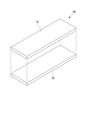
- 1 is an exploded perspective view showing the configuration of a laminated glass 10
- FIG. 3 is a plan view showing the arrangement of the light control cell 20 and the covering member 50.
- FIG. 3 is an exploded perspective view showing the configuration of a covering member 50
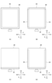
- FIG. (A) to (D) are plan views showing various forms of the covering member 50 provided in the light control cell 20.
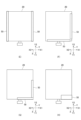
- FIG. (E) to (H) are plan views showing various forms of the covering member 50 provided in the light control cell 20.
- FIG. (A) to (E) are diagrams for explaining the manufacturing process of the laminated glass 10 having the light control cell 20 of the first embodiment. It is sectional drawing of 1 A of light modulation apparatuses which concern on 2nd Embodiment.
- FIG. 1 (described later), which serves as a reference for this coordinate system, is a diagram of the laminated glass 10 viewed from a direction (normal direction) perpendicular to the plate surface.
- the X-axis and Y-axis shown in FIG. 1 are axes parallel to the plate surface of the laminated glass 10, respectively.
- the laminated glass 10 shown in this embodiment has a rectangular shape, and a line parallel to one side thereof is the X-axis.
- One of the X directions along the X axis is defined as the X1 direction, and the direction opposite to the X1 direction is defined as the X2 direction.
- a line parallel to the side perpendicular to the X axis is the Y axis.
- one direction is the Y1 direction
- the opposite direction to the Y1 direction is the Y2 direction.
- the line perpendicular to the XY axis is the Z axis.
- One of the Z directions along the Z axis is the Z1 direction
- the opposite direction to the Z1 direction is the Z2 direction.
- direction is also referred to as "side”. Note that the numerical values, shapes, materials, and the like described in this specification are examples of embodiments, and are not limited to these, and may be appropriately selected and used.
- the light control device of each embodiment described below can be applied to various technical fields where control of light transmittance is required, and the scope of application is not particularly limited.
- the dimmer is intended for light control of, for example, window glass of buildings, showcases, indoor transparent partitions, vehicle windows (for example, front, side, rear, roof windows, etc.), partition boards inside vehicles, etc. Can be installed in parts. This makes it possible to control the amount of light incident on the inside of a building, vehicle, or the like, or to control the amount of light incident on a predetermined area inside the building, vehicle, or the like.
- the light control device of each embodiment may be configured with a three-dimensional shape having a curved surface shape.
- the light control device may have a shape that is convex on one side.
- the light modulation device is not limited to this, and the surface shape may be a planar shape (for example, flat plate shape), for example.
- the surface shape of the light control device is a planar shape (two-dimensional shape).
- FIG. 1 is a plan view of a light control device 1 according to the first embodiment.
- FIG. 2 is a cross-sectional view showing the s1-s1 cross section of FIG.
- FIG. 3 is an exploded perspective view showing the configuration of the laminated glass 10.
- FIG. 4 is a plan view showing the arrangement of the light control cell 20 and the covering member 50.
- FIG. 5 is an exploded perspective view showing the structure of the covering member 50. As shown in FIG.
- the light control device 1 of the first embodiment includes a laminated glass 10 and a frame member 11.
- the light control device 1 is a liquid crystal device in the present embodiment and the second embodiment, and is, for example, a device capable of controlling light transmittance by applying a voltage.
- the frame member 11 is a member that covers the outer peripheral portion of the laminated glass 10 in a frame shape.
- the frame member 11 is provided with an opening 11a. As shown in FIG. 2, the openings 11a are provided on both the front side (Z1 side) and the back side (Z2 side) of the light control device 1. As shown in FIG.
- the frame member 11 has a function of protecting the outer peripheral portion of the laminated glass 10 and a function of enabling the laminated glass 10 to be attached to a portion for adjusting light.
- the frame member 11 functions as a window frame.
- the frame member 11 is not limited to a shape that covers the outer peripheral portion of the laminated glass 10 in a frame shape, and may have a shape that partially covers the laminated glass 10 . Further, in the light control device, a configuration in which the frame member is not provided on the laminated glass may be adopted.
- the laminated glass 10 is a laminate including a light control cell 20 (described later) capable of controlling light transmittance by applying a voltage. As shown in FIGS. 2 and 3, the laminated glass 10 includes a first glass plate (first transparent substrate) 41, a second glass plate (second transparent substrate) 42, a first intermediate layer 31, and a second intermediate layer 32. , a dimming cell 20 and a covering member 50 . 1, illustration of the covering member 50 is omitted.
- the first glass plate 41 and the second glass plate 42 are members arranged facing each other on the front and back surfaces of the laminated glass 10 .
- the first glass plate 41 is arranged on the front side (Z1 side) of the laminated glass 10
- the second glass plate 42 is arranged on the back side (Z2 side) of the laminated glass 10 .
- plate glass with high translucency such as soda lime glass (blue plate glass), borosilicate glass (white plate glass), quartz glass, soda glass, potash glass, etc. may be used. can be done.
- resin glass can be used as the first glass plate 41 and the second glass plate 42 .
- the resin glass for example, one made of polycarbonate, acryl, or the like can be used.
- polycarbonate is preferable in terms of heat resistance and strength.
- the glass plate may be subjected to surface treatment such as hard coating, depending on required properties such as scratch resistance.
- resin glass is preferable to inorganic glass in terms of weight reduction.
- inorganic glass is preferable to resin glass in terms of cost, heat resistance, scratch resistance, and the like.
- the first intermediate layer 31 is provided between the first glass plate 41 and the light control cell 20, and is a layer that joins the first glass plate 41 and the light control cell 20 to each other.
- the first intermediate layer 31 is made of OCR (Optical Clear Resin).
- OCR is a cured product obtained by curing a liquid curable adhesive layer composition containing a polymerizable compound. Specifically, OCR applies a liquid resin obtained by mixing a base resin such as an acrylic resin, a silicone resin, or a urethane resin and an additive to an object, and then uses, for example, ultraviolet rays (UV). It is hardened.
- the first intermediate layer 31 made of OCR preferably has optical transparency, heat resistance up to at least about 120° C., moist heat resistance, and weather resistance.
- the second intermediate layer 32 is provided between the second glass plate 42 and the light control cell 20, and is a layer that joins the second glass plate 42 and the light control cell 20 to each other.
- the second intermediate layer 32 is made of OCA (Optical Clear Adhesive).
- the OCA is, for example, a layer made as follows. First, a release film such as polyethylene terephthalate (PET) is coated with a liquid curable adhesive layer composition containing a polymerizable compound, which is then cured using, for example, ultraviolet rays (UV) to form an OCA sheet.
- the curable adhesive layer composition may be an optical pressure-sensitive adhesive such as an acrylic resin, a silicone resin, or a urethane resin.
- the second intermediate layer 32 made of OCA preferably has optical transparency, heat resistance up to at least about 120° C., moist heat resistance, and weather resistance.
- the light control cell 20 is a liquid crystal cell in this embodiment, and is, for example, a film whose light transmittance can be controlled by voltage application.
- the light control cell 20 is sandwiched between the first glass plate 41 and the second glass plate 42 with intermediate layers (31, 32) interposed therebetween.
- the light control cell 20 includes a guest-host type liquid crystal composition using a dichroic dye as a liquid crystal layer 23 (described later).
- the dimming cell 20 comprises a first laminate 21, a second laminate 22, and a liquid crystal layer 23 disposed between the first laminate 21 and the second laminate 22. .
- the thickness of the dimming cell 20 is, for example, about 200 to 1000 ⁇ m.
- the light control cell 20 includes an active area A1 whose light transmittance is controlled and a non-active area A2 adjacent to the active area A1.
- the non-active area A2 is an area that is not used for light transmittance control.
- the area overlapping the frame member 11 in the normal direction (Z direction) of the light control cell 20 is the non-active area A2.
- an area that does not overlap with the frame member 11 in the normal direction (Z direction) of the light control cell 20 in other words, an area that overlaps with the opening 11a of the frame member 11 is the active area A1.
- non-active area A2 of the present embodiment is an area that does not have the function of controlling the transmittance of light or has the function of controlling the transmittance of the light in the outer peripheral portion adjacent to the active area A1 of the light control cell 20. Although provided, it corresponds to an area that is not used as the active area A1 in terms of design.
- the first laminate 21 includes a first substrate 24A, a first transparent electrode 25A and a first alignment layer 26A.
- the above parts are laminated in order of the first substrate 24A, the first transparent electrode 25A, and the first orientation layer 26A from the front side (Z1 side) to the back side (Z2 side).
- the second laminate 22 also includes a second substrate 24B, a second transparent electrode 25B and a second alignment layer 26B.
- the above parts are laminated in order of the second substrate 24B, the second transparent electrode 25B, and the second orientation layer 26B from the back side (Z2 side) to the front side (Z1 side).
- a plurality of bead spacers 27 are arranged between the first laminate 21 and the second laminate 22 .
- the liquid crystal layer 23 is formed by filling liquid crystal between the plurality of bead spacers 27 between the first laminate 21 and the second laminate 22 .
- the plurality of bead spacers 27 may be arranged irregularly or may be arranged regularly.
- the dimming cell 20 changes the voltage applied to the first transparent electrode 25A and the second transparent electrode 25B provided on the first laminate 21 and the second laminate 22, respectively, so that the guest-host liquid crystal of the liquid crystal layer 23 is changed.
- the composition changes the orientation of the liquid crystal material, thereby controlling the light transmittance.
- the first base material 24A and the second base material 24B are made of transparent resin, and flexible films can be applied.
- a transparent resin film having a small optical anisotropy and a transmittance of 80% or more in the visible wavelength range (380 nm or more and 800 nm or less).
- Materials for the transparent resin film include, for example, acetylcellulose-based resins such as triacetylcellulose (TAC), polyester-based resins such as polyethylene terephthalate (PET) and polyethylene naphthalate (PEN), polyethylene (PE), and polypropylene (PP).
- polystyrene, polymethylpentene, EVA and other polyolefin resins polyvinyl chloride, polyvinylidene chloride and other vinyl resins, acrylic resins, polyurethane resins, polysulfone (PSF), polyethersulfone (PES), polycarbonate ( PC), polyether, polyetherketone (PEK), (meth)acrylonitrile, cycloolefin polymer (COP), cycloolefin copolymer and the like.
- the transparent resin film As a material for the transparent resin film, resins such as polycarbonate, cycloolefin polymer, and polyethylene terephthalate are particularly preferable. Also, the thickness of the transparent resin film used as the first base material 24A and the second base material 24B can be appropriately selected within a range in which the transparent resin film has flexibility, although it depends on the material. The thickness of each of the first base material 24A and the second base material 24B may be 50 ⁇ m or more and 200 ⁇ m or less. In this embodiment, a polyethylene terephthalate film having a thickness of 125 ⁇ m is applied as an example of the first base material 24A and the second base material 24B.
- the first transparent electrode 25A and the second transparent electrode 25B are composed of transparent conductive films laminated on the first substrate 24A and the second substrate 24B (transparent resin film), respectively.
- transparent resin film various transparent electrode materials that are applied to this type of transparent resin film can be applied, and an oxide-based transparent metal thin film having a total light transmittance of 50% or more can be used. . Examples include tin oxide, indium oxide, and zinc oxide.
- Tin oxide (SnO 2 )-based materials include Nesa (tin oxide SnO 2 ), ATO (Antimony Tin Oxide), and FTO (fluorine-doped tin oxide).
- Indium oxide (In 2 O 3 )-based materials include indium oxide, ITO (Indium Tin Oxide), and IZO (Indium Zinc Oxide).
- Zinc oxide (ZnO)-based materials include zinc oxide, AZO (aluminum-doped zinc oxide), and GZO (gallium-doped zinc oxide).
- the transparent conductive film forming the first transparent electrode 25A and the second transparent electrode 25B is made of ITO.
- the bead spacer 27 is a member that defines the thickness (cell gap) of the liquid crystal layer 23 .
- spherical bead spacers are used as the bead spacers 27 .
- the diameter of the bead spacer 27 may range from 1 ⁇ m to 20 ⁇ m, preferably from 3 ⁇ m to 15 ⁇ m.
- the bead spacers 27 can be widely applied with inorganic materials such as silica, organic materials, core-shell structures combining these materials, and the like.
- the bead spacer 27 may be configured in a rod shape such as a cylindrical shape, an elliptical columnar shape, a polygonal columnar shape, or the like, in addition to the spherical configuration.
- the bead spacers 27 are made of a transparent member, but if necessary, a colored material may be applied to adjust the color.
- the bead spacers 27 are provided on the second laminate 22, but are not limited to this. may be provided only in Also, the bead spacers 27 may not necessarily be provided. Also, columnar spacers may be used instead of the bead spacers 27 or together with the bead spacers 27 .
- the first alignment layer 26A and the second alignment layer 26B are members for orienting the liquid crystal molecule group contained in the liquid crystal layer 23 in a desired direction.
- the first alignment layer 26A and the second alignment layer 26B are formed by photo-alignment layers.
- a photo-alignment material that can be applied to the photo-alignment layer various materials to which a photo-alignment technique can be applied can be widely applied. For example, photodegradation type, photodimerization type, photoisomerization type and the like can be mentioned. In a first embodiment, a photodimerization type material is used.
- photodimerizable materials include cinnamate, coumarin, benzylidenephthalimidine, benzylideneacetophenone, diphenylacetylene, stilbazole, uracil, quinolinone, maleimide, and polymers having cinnamylideneacetic acid derivatives.
- a polymer containing either or both of cinnamate and coumarin is preferably used because of its good orientation control force.
- a rubbing alignment layer may be used instead of the photo-alignment layer.
- the rubbing treatment may not be performed, or the alignment layer may be produced by performing a rubbing treatment and performing a molding treatment to form a fine line-shaped concave-convex shape.
- the light control cell 20 includes the first alignment layer 26A and the second alignment layer 26B, but is not limited to this. may be
- a guest-host liquid crystal composition and a dichroic dye composition can be widely applied to the liquid crystal layer 23 .
- the guest-host liquid crystal composition may contain a chiral agent so that when the liquid crystal material is horizontally aligned, it is aligned in a spiral shape in the thickness direction of the liquid crystal layer 23 .
- a ring-shaped or frame-shaped sealing material 28 is arranged in plan view so as to surround the liquid crystal layer 23 .
- the sealing material 28 holds the first layered body 21 and the second layered body 22 together and prevents leakage of the liquid crystal material.
- Thermosetting resins such as epoxy resins and acrylic resins, ultraviolet curable resins, and the like can be applied to the sealing material 28 .
- a nematic liquid crystal compound, a smectic liquid crystal compound, and a cholesteric liquid crystal compound can be applied to the liquid crystal layer 23 as liquid crystal compounds having no polymerizable functional group.
- nematic liquid crystal compounds include biphenyl-based compounds, terphenyl-based compounds, phenylcyclohexyl-based compounds, biphenylcyclohexyl-based compounds, phenylbicyclohexyl-based compounds, trifluoro-based compounds, phenyl benzoate-based compounds, and phenyl cyclohexylbenzoate-based compounds.
- phenyl phenylbenzoate compounds phenyl bicyclohexylcarboxylate compounds, azomethine compounds, azo compounds, and azooxy compounds, stilbene compounds, tolan compounds, ester compounds, bicyclohexyl compounds, phenylpyrimidine compounds , biphenylpyrimidine-based compounds, pyrimidine-based compounds, and biphenylethyne-based compounds.
- smectic liquid crystal compounds include ferroelectric polymer liquid crystal compounds such as polyacrylate, polymethacrylate, polychloroacrylate, polyoxirane, polysiloxane, and polyester.
- cholesteric liquid crystal compounds include cholesteryl linoleate, cholesteryl oleate, cellulose, cellulose derivatives, and polypeptides.
- Dichroic dyes used in the guest-host system include liquid crystal-soluble and highly dichroic dyes such as azo, anthraquinone, quinophthalone, perylene, indigo, thioindigo, and merocyanine dyes. dichroic dyes such as dyes, styryl dyes, azomethine dyes, and tetrazine dyes.
- the alignment control force related to pretilt is set in a certain direction for the first alignment layer 26A and the second alignment layer 26B so that the alignment of the guest-host liquid crystal composition is formed when there is no electric field when the light is blocked. It consists of horizontal alignment layers, which are normally dark. It should be noted that the light control cell 20 may be set to normally clear when the electric field is applied when the light is shielded. Here, normally dark means a structure in which light transmittance is minimized when no voltage is applied to the liquid crystal, resulting in a black screen. Normally clear is a structure in which light transmittance is maximized and the liquid crystal becomes transparent when no voltage is applied.
- the haze value of the light-transmitting light control cell 20 is desirably 30% or less, and more desirably 15% or less. In order to achieve such a low haze value, it is desirable that the liquid crystal mixture contains no polymerizable compound.
- the light control cell 20 may be configured to include a liquid crystal layer 23 such as a TN (Twisted Nematic) method, a VA (Vertical Alignment) method, or an IPS (In-Plane-Switching) method that does not use a dichroic dye composition.
- a liquid crystal layer 23 such as a TN (Twisted Nematic) method, a VA (Vertical Alignment) method, or an IPS (In-Plane-Switching) method that does not use a dichroic dye composition.
- a liquid crystal layer 23 such as a TN (Twisted Nematic) method, a VA (Vertical Alignment) method, or an IPS (In-Plane-Switching) method that does not use a dichroic dye composition.
- a flexible printed wiring board 29 (see FIG. 3) is provided for electrical connection between the first transparent electrode 25A and the second transparent electrode 25B and the outside.
- the flexible printed wiring board 29 is connected by being sandwiched between the first transparent electrode 25A and the second transparent electrode 25B in a region where the liquid crystal layer 23 is not sandwiched between the first transparent electrode 25A and the second transparent electrode 25B.
- the flexible printed wiring board 29 may have a form in which it is not sandwiched between the first transparent electrode 25A and the second transparent electrode 25B, for example.
- the covering member 50 is a member for adjusting the thickness of the first intermediate layer 31 interposed between the outer peripheral portion of the light control cell 20 and the first glass plate 41 .
- the peripheral portion of the dimming cell 20 refers to the non-active area A2 or a region including part of the non-active area A2.
- the covering member 50 of the first embodiment is arranged on the surface (Z1 side) of the light control cell 20 .
- the covering member 50 is formed in an elongated rectangular shape. In this embodiment, two covering members 50 are provided on each side of the light control cell 20 . Between the adjacent covering members 50, gaps (clearances) S are provided as shown in FIG.
- the light control cell 20 has a region that overlaps with the covering member 50 and a region that does not overlap with the covering member 50 .
- the covering member 50 may not be provided as shown in FIG. 4, and may be continuous along one side of the light control cell 20 as described later. 4, the outer edge of the covering member 50 protrudes outside the outer peripheral edge 20a of the light control cell 20, but is arranged so that the outer edge coincides with the outer peripheral edge 20a of the light control cell 20. may have been
- the covering member 50 includes a film material 51 and a bonding layer 52, as shown in FIG.
- the film material 51 is a member arranged on the first glass plate 41 side in the covering member 50 .
- the film material 51 for example, in addition to polyethylene terephthalate (PET), the same material as the above-described first base material 24A and second base material 24B can be used.
- PET polyethylene terephthalate
- the covering member 50 may be transparent or opaque. However, since the following effects can be obtained by making the covering member 50 transparent, it is more desirable to make the covering member 50 transparent. As for the effect of making the covering member 50 transparent, it is possible to minimize the possibility of overlooking the problem with the surrounding area of the light-modulating cell during the manufacturing process, if the covering member 50 is transparent. It can be made smaller.
- the degree of transparency of the covering member 50 is desirably 50% or more, and more desirably 80% or more.
- the above transmittance is a value in the visible light region (400 nm to 800 nm) and is measured with a spectrophotometer.
- the thickness of the covering member 50 is preferably 25% or more and 95% or less, more preferably 40% or more and 90% or less, of the thickness of the first intermediate layer 31 .
- the thickness of the film material 51 is desirably, for example, 50 to 250 ⁇ m, more desirably 100 to 250 ⁇ m.
- the bonding layer 52 is a layer that bonds the film material 51 and the light control cell 20 .
- the bonding layer 52 is arranged on the side of the light control cell 20 in the covering member 50 .
- OCA, OCR, or the like can be used as the bonding layer 52 .
- the thickness of the bonding layer 52 is, for example, 15 to 250 ⁇ m.
- the covering member 50 may have a configuration in which the bonding layer 52 is omitted. As shown in FIG. 2, the covering member 50 is provided in a region that does not overlap the active area A1 of the light control cell 20 in plan view.
- the covering member 50 of the present embodiment is provided so as to cover almost the entire non-active area A2 of the light control cell 20 except for the gap S. In addition, when the covering member 50 is provided in one place, it may be applied to the area of the covering member 50 in that one place.
- FIG. 6A to 6D and 7E to 7H are plan views showing various forms of the covering member 50 provided on the light control cell 20.
- FIG. FIG. 6A shows a form in which a frame-shaped covering member 50 is provided on the outer peripheral portion of the light control cell 20 .
- FIG. 6B shows a form in which a covering member 50 is provided so as to cover the four sides of the light control cell 20.
- FIG. FIG. 6(C) shows a form in which a covering member 50 is provided so as to cover one side of the light control cell 20 .
- FIG. 6C shows a mode in which the covering member 50 is provided on one side of the light control cell 20 on the Y1 side. may be FIG.
- FIG. 6D shows a form in which a covering member 50 is provided so as to cover three sides of the light control cell 20.
- FIG. FIG. 6D shows a mode in which the covering member 50 is provided on three sides of the light control cell 20 except for the Y2 side. It is good also as a form provided in.
- FIG. 7(E) shows a form in which the covering member 50 is provided so as to cover the two opposing sides of the light control cell 20 .
- FIG. 7(E) shows a mode in which the covering member 50 is provided on two sides of the light control cell 20 on the X1 side and the X2 side. It is good also as a form provided in the side.
- FIG. 7(F) shows a form in which a covering member 50 is provided so as to cover two adjacent sides of the light control cell 20 .
- FIG. 7F shows a mode in which the covering member 50 is provided on two sides of the light control cell 20, namely, the X1 side and the Y1 side. can be placed in any position.
- the covering member 50 may be provided on two sides of the dimming cell 20, namely, the X2 side and the Y2 side.
- FIG. 7(G) shows a form in which a covering member 50 having a length shorter than one side of the light control cell 20 is provided on two adjacent sides of the light control cell 20 .
- FIG. 7G shows a mode in which the covering member 50 is provided on two sides of the light control cell 20, namely, the X1 side and the Y1 side. can be placed in any position.
- the covering member 50 may be provided on two sides of the dimming cell 20, namely, the X2 side and the Y2 side.
- the length of the covering member 50 provided at each position may be different from that shown in FIG. 7(G).
- FIG. 7(H) shows a form in which a covering member 50 having a shorter length in the X direction than one side of the light control cell 20 and a wider width in the Y direction is provided on one side of the light control cell 20.
- FIG. 7(H) shows a form in which the covering member 50 is provided on the Y1 side and the X1 side of the light control cell 20.
- the covering member 50 is provided on one side of the light control cell 20, It may be provided at any position as long as it is shorter and wider than one side.
- the light control cell 20 when the light control cell 20 (light control device 1) is placed vertically, for example, when the Y direction of the light control cell 20 is the vertical direction and the Y2 side is the upper side, the light control cell In 20, liquid crystal accumulation is likely to occur on the lower side (Y1 side) of the active area A1. Therefore, when the light control cell 20 is placed vertically in the above direction, by arranging the covering member 50 on the lower side (Y1 side) of the light control cell 20, the liquid crystal pool generated on the Y1 side of the active area A1 is reduced. can be made inconspicuous. When the light control cell 20 is placed vertically in the above direction, it is preferable to arrange the covering member 50 as shown in FIGS. form.
- FIG. 8A to 8E are diagrams for explaining the manufacturing process of the laminated glass 10 having the light control cell 20 of the first embodiment.
- the second glass plate 42 is placed on a workbench (not shown), and the second intermediate layer 32 made of OCA is formed on the second glass plate 42. Laminate.
- the light control cell 20 is laminated on the second intermediate layer 32 .
- the covering member 50 is arranged around the outer periphery of the light control cell 20 (for example, the form shown in FIG. 3). The covering member 50 is laminated so that the bonding layer 52 is on the side of the light control cell 20 and the film material 51 is on the side opposite to the light control cell 20 .
- uncured OCR which will be the first intermediate layer 31, is applied on the laminate obtained in FIG. 8(C). OCR is applied by, for example, a dispenser, slit coater, or other application nozzle (not shown).
- the first glass plate 41 is bonded onto the first intermediate layer 31.
- the first intermediate layer 31 is an OCR containing a non-pressure-bonding adhesive component
- the first glass plate 41 can be bonded by atmospheric bonding or vacuum bonding without applying pressure.
- the OCR can be cured by irradiating the laminate with ultraviolet rays (UV).
- UV ultraviolet rays
- the light control cell 20 of this embodiment has a region that overlaps with the covering member 50 and a region that does not overlap with the covering member 50 . Therefore, in the laminated glass 10 sandwiching the light control cell 20, the thickness of the first intermediate layer 31 in the region where the covering member 50 is arranged is thinner than the region where the covering member 50 is not arranged.
- the OCR that contacts the light control cell 20 in the region that does not overlap with the covering member 50 expands more than the OCR that contacts the light control cell 20 in the region that overlaps with the covering member 50 . Due to the expansion, the OCR contacting the light control cell 20 in the region not overlapping the covering member 50 presses the light control cell 20 more strongly than the OCR contacting the light control cell 20 in the region overlapping the covering member 50 . As a result, part of the liquid crystal present in the region that does not overlap with the covering member 50 moves to the region that overlaps with the covering member 50, that is, the region where OCR expansion is small.
- the covering member 50 in a region where the liquid crystal is to be moved in the light control cell 20, part of the liquid crystal filled in the cell can be selectively collected in that region.
- the region where liquid crystal pooling occurs can be controlled. Therefore, in the light control cell 20, by arranging the covering member 50 in a region adjacent to a region in which liquid crystal pooling is not desired, it is possible to suppress appearance defects of the light control cell 20 in that region.
- the light control cell 20 has the covering member 50 arranged along the outer peripheral portion as shown in FIG.
- the thickness of layer 31 becomes thinner than other areas (eg, active area A1). Therefore, when the OCR that forms the first intermediate layer 31 is cured during the production of the laminated glass 10, the expansion of the OCR in the outer peripheral portion of the light control cell 20 is relatively greater than the expansion of the OCR in the central portion. become smaller. Accordingly, when the OCR is cured, the OCR in contact with the central portion of the light control cell 20 expands more than the outer peripheral portion and presses the central portion of the light control cell 20 more strongly.
- part of the liquid crystal present in the central portion of the light control cell 20 moves to the outer peripheral portion where the expansion of the OCR is small. That is, part of the liquid crystal present in the central portion of the light control cell 20 (laminated glass 10) is collected in the non-active area A2 where the covering member 50 is arranged during manufacture.
- the manufactured light control cell 20 laminated glass 10
- the liquid crystal pools in the central portion of the light control cell 20. Since it is less likely to occur, it is possible to suppress appearance defects and deterioration of dimming performance mainly in the active area A1.
- the covering member 50 is provided on the light control cell 20 side. Therefore, in the step shown in FIG. 8(C), the work of arranging the covering member 50 on the outer peripheral portion of the light control cell 20 can be easily performed.
- the covering member 50 is composed of a film material 51 and a bonding layer 52 (see FIG. 5). Therefore, in the step shown in FIG. 8D, when the OCR is applied onto the light control cell 20, the position of the covering member 50 arranged on the outer peripheral portion of the light control cell 20 can be made less likely to shift.
- the covering member 50 is provided at two positions on each side of the light control cell 20, and the gap S is provided between the adjacent covering members 50. is provided. Therefore, in the process shown in FIG. 8(E), when the uncured OCR is sandwiched between the first glass plate 41 and the light control cell 20 to form the first intermediate layer 31, excess air is removed from the gap S. can be discharged.
- a light modulation device 1A of the second embodiment differs from that of the first embodiment in the position where the covering member 50 is arranged.
- 1 A of light modulation apparatuses of 2nd Embodiment other structures are the same as that of 1st Embodiment. Therefore, in description of 2nd Embodiment, only sectional drawing of 1 A of light control apparatuses is illustrated, and other figures are abbreviate
- the same reference numerals as in the first embodiment are given to members and the like that are the same as those in the first embodiment, and overlapping descriptions are omitted.
- FIG. 9 is a cross-sectional view of a light control device 1A according to the second embodiment.
- FIG. 9 corresponds to a cross-sectional view (FIG. 2) of the light control device 1 of the first embodiment.
- the covering member 50 is arranged on the surface of the first glass plate 41 (Z2 side).
- the film material 51 (see FIG. 5) is arranged on the light control cell 20 side.
- the bonding layer 52 (see FIG. 5) is arranged on the first glass plate 41 side.
- the area where the covering member 50 is arranged is the same as in the first embodiment.
- the covering member 50 is provided in a region that does not overlap the active area A1 of the light control cell 20 in plan view.
- the arrangement of the covering member 50 is, for example, the forms of FIGS. 4, 6 (A) to (D) and 7 (E) to (H) of the first embodiment. can be applied.
- the coating member 50 arranged along the outer peripheral portion of the light control cell 20 prevents part of the liquid crystal present in the center of the light control cell 20 from being They can be collected within the area of the active area A2. Therefore, according to the light control device 1A of the second embodiment, when the light control cell 20 (laminated glass 10) is exposed to a high temperature environment, the deterioration of the appearance and the light control performance in the active area A1 can be prevented. can be suppressed.
- the covering member 50 has an elongated rectangular shape
- the shape of the covering member 50 may be, for example, a square, a rectangle, a parallelogram, a trapezoid, a circle, an ellipse, or the like in plan view. That is, the shape of the covering member 50 in plan view can be changed as appropriate.
- the dimming cell 20 is rectangular in plan view, but it is not limited to this.
- the shape of the dimming cell 20 may be, for example, a square in plan view, a parallelogram, a trapezoid, or the like. That is, the shape of the light control cell 20 in plan view can be changed as appropriate.
- the configuration in which the covering member 50 is provided on the light control cell 20 side (first embodiment) and the configuration in which the covering member 50 is provided on the first glass plate 41 side (second embodiment) have been described, but are limited to this. not.
- the first intermediate layer 31 (OCR) may be sandwiched between the covering members 50 on the light control cell 20 side and the first glass plate 41 side.
- the covering member 50 provided on the light control cell 20 side and the covering member 50 provided on the first glass plate 41 side may have the same shape or arrangement, or may be different.
- the present invention is not limited to this.
- a functional film such as a UV cut film may be laminated on one side or both sides of the light control cell 20 .
- the example in which the first intermediate layer 31 of the laminated glass 10 is made of OCR and the second intermediate layer 32 is made of OCA has been described, but the present invention is not limited to this.
- Each of the first intermediate layer 31 and the second intermediate layer 32 may be configured by OCR.
- Reference Signs List 1 1A light control device 10 laminated glass 11 frame member 20 light control cell 31 first intermediate layer 32 second intermediate layer 41 first glass plate 42 second glass plate 50 covering member 51 film material 52 bonding layer S gap A1 active Area A2 Inactive area
Landscapes
- Physics & Mathematics (AREA)
- Nonlinear Science (AREA)
- Chemical & Material Sciences (AREA)
- Crystallography & Structural Chemistry (AREA)
- Engineering & Computer Science (AREA)
- Optics & Photonics (AREA)
- General Physics & Mathematics (AREA)
- Structural Engineering (AREA)
- Mathematical Physics (AREA)
- Architecture (AREA)
- Civil Engineering (AREA)
- Mechanical Engineering (AREA)
- Liquid Crystal (AREA)
Priority Applications (6)
| Application Number | Priority Date | Filing Date | Title |
|---|---|---|---|
| JP2023552552A JP7401038B2 (ja) | 2021-11-19 | 2022-10-31 | 合わせガラス及び液晶装置 |
| CN202280074588.8A CN118302713A (zh) | 2021-11-19 | 2022-10-31 | 夹层玻璃及液晶装置 |
| KR1020247014546A KR20240107110A (ko) | 2021-11-19 | 2022-10-31 | 접합 유리 및 액정 장치 |
| EP22895416.0A EP4435504A4 (en) | 2021-11-19 | 2022-10-31 | LAMINATED GLASS AND LIQUID CRYSTAL DEVICE |
| US18/711,410 US20250010587A1 (en) | 2021-11-19 | 2022-10-31 | Laminated glass and liquid crystal device |
| JP2023205185A JP2024015500A (ja) | 2021-11-19 | 2023-12-05 | 合わせガラス及び液晶装置 |
Applications Claiming Priority (2)
| Application Number | Priority Date | Filing Date | Title |
|---|---|---|---|
| JP2021188367 | 2021-11-19 | ||
| JP2021-188367 | 2021-11-19 |
Publications (1)
| Publication Number | Publication Date |
|---|---|
| WO2023090133A1 true WO2023090133A1 (ja) | 2023-05-25 |
Family
ID=86396840
Family Applications (1)
| Application Number | Title | Priority Date | Filing Date |
|---|---|---|---|
| PCT/JP2022/040615 Ceased WO2023090133A1 (ja) | 2021-11-19 | 2022-10-31 | 合わせガラス及び液晶装置 |
Country Status (6)
| Country | Link |
|---|---|
| US (1) | US20250010587A1 (https=) |
| EP (1) | EP4435504A4 (https=) |
| JP (2) | JP7401038B2 (https=) |
| KR (1) | KR20240107110A (https=) |
| CN (1) | CN118302713A (https=) |
| WO (1) | WO2023090133A1 (https=) |
Families Citing this family (1)
| Publication number | Priority date | Publication date | Assignee | Title |
|---|---|---|---|---|
| JP2023096553A (ja) * | 2021-12-27 | 2023-07-07 | 凸版印刷株式会社 | 調光積層体、および調光装置 |
Citations (5)
| Publication number | Priority date | Publication date | Assignee | Title |
|---|---|---|---|---|
| JP2007326763A (ja) * | 2006-06-09 | 2007-12-20 | Nippon Sheet Glass Co Ltd | シート封入合わせガラス |
| JP2017187810A (ja) | 2015-11-13 | 2017-10-12 | 大日本印刷株式会社 | 調光フィルム及び合わせガラス |
| JP2018058747A (ja) * | 2016-09-28 | 2018-04-12 | 株式会社ビーキャット | 調光機能付き板状構造体 |
| WO2019026849A1 (ja) * | 2017-07-31 | 2019-02-07 | 大日本印刷株式会社 | 合わせガラス、合わせガラスの製造方法 |
| WO2019198748A1 (ja) | 2018-04-11 | 2019-10-17 | 大日本印刷株式会社 | 合わせガラス、合わせガラスの製造方法、調光装置、調光セル及び調光装置用積層体 |
Family Cites Families (1)
| Publication number | Priority date | Publication date | Assignee | Title |
|---|---|---|---|---|
| JP6847305B2 (ja) * | 2018-12-20 | 2021-03-24 | ベバスト エスエーWebasto SE | 液晶配列を含む複合材を有する車両用窓ガラス |
-
2022
- 2022-10-31 JP JP2023552552A patent/JP7401038B2/ja active Active
- 2022-10-31 EP EP22895416.0A patent/EP4435504A4/en active Pending
- 2022-10-31 KR KR1020247014546A patent/KR20240107110A/ko active Pending
- 2022-10-31 CN CN202280074588.8A patent/CN118302713A/zh active Pending
- 2022-10-31 WO PCT/JP2022/040615 patent/WO2023090133A1/ja not_active Ceased
- 2022-10-31 US US18/711,410 patent/US20250010587A1/en active Pending
-
2023
- 2023-12-05 JP JP2023205185A patent/JP2024015500A/ja active Pending
Patent Citations (5)
| Publication number | Priority date | Publication date | Assignee | Title |
|---|---|---|---|---|
| JP2007326763A (ja) * | 2006-06-09 | 2007-12-20 | Nippon Sheet Glass Co Ltd | シート封入合わせガラス |
| JP2017187810A (ja) | 2015-11-13 | 2017-10-12 | 大日本印刷株式会社 | 調光フィルム及び合わせガラス |
| JP2018058747A (ja) * | 2016-09-28 | 2018-04-12 | 株式会社ビーキャット | 調光機能付き板状構造体 |
| WO2019026849A1 (ja) * | 2017-07-31 | 2019-02-07 | 大日本印刷株式会社 | 合わせガラス、合わせガラスの製造方法 |
| WO2019198748A1 (ja) | 2018-04-11 | 2019-10-17 | 大日本印刷株式会社 | 合わせガラス、合わせガラスの製造方法、調光装置、調光セル及び調光装置用積層体 |
Non-Patent Citations (1)
| Title |
|---|
| See also references of EP4435504A4 |
Also Published As
| Publication number | Publication date |
|---|---|
| JP2024015500A (ja) | 2024-02-02 |
| EP4435504A4 (en) | 2025-11-26 |
| JPWO2023090133A1 (https=) | 2023-05-25 |
| JP7401038B2 (ja) | 2023-12-19 |
| KR20240107110A (ko) | 2024-07-08 |
| EP4435504A1 (en) | 2024-09-25 |
| US20250010587A1 (en) | 2025-01-09 |
| CN118302713A (zh) | 2024-07-05 |
Similar Documents
| Publication | Publication Date | Title |
|---|---|---|
| JP6673537B2 (ja) | 合わせガラス、合わせガラスの製造方法、調光装置、調光セル及び調光装置用積層体 | |
| US20230202147A1 (en) | Light modulating device and manufacturing method | |
| JP7286928B2 (ja) | 調光装置およびその製造方法 | |
| JP7839487B2 (ja) | 調光装置及びその製造方法、並びに液晶装置 | |
| JP7404910B2 (ja) | 調光セルおよび調光装置 | |
| JP7432139B2 (ja) | 調光装置 | |
| JP7420298B2 (ja) | 調光セルおよびその製造方法、ならびに調光装置およびその製造方法 | |
| JP7294003B2 (ja) | 調光装置 | |
| JP7401038B2 (ja) | 合わせガラス及び液晶装置 | |
| JP7451898B2 (ja) | 調光装置、調光装置用積層体及び調光セル | |
| JP7539039B2 (ja) | 調光装置及びその製造方法 | |
| JP7409125B2 (ja) | 調光装置及びその製造方法 | |
| JP7700646B2 (ja) | 合わせガラス、液晶装置及び合わせガラスの固定方法 | |
| JP7806475B2 (ja) | 液晶装置 | |
| JP7632170B2 (ja) | 液晶装置の製造方法 | |
| JP7779152B2 (ja) | 液晶セル、液晶装置 | |
| JP2020170127A (ja) | 調光シート | |
| JP2026020991A (ja) | 調光装置及び調光装置の製造方法 | |
| WO2026028769A1 (ja) | 調光装置及び調光装置の製造方法 | |
| JP2021124678A (ja) | 調光装置の製造方法 | |
| CN119678097A (zh) | 调光部件、调光部件的制造方法、调光体 |
Legal Events
| Date | Code | Title | Description |
|---|---|---|---|
| 121 | Ep: the epo has been informed by wipo that ep was designated in this application |
Ref document number: 22895416 Country of ref document: EP Kind code of ref document: A1 |
|
| WWE | Wipo information: entry into national phase |
Ref document number: 2023552552 Country of ref document: JP |
|
| WWE | Wipo information: entry into national phase |
Ref document number: 202280074588.8 Country of ref document: CN |
|
| WWE | Wipo information: entry into national phase |
Ref document number: 18711410 Country of ref document: US |
|
| WWE | Wipo information: entry into national phase |
Ref document number: 2022895416 Country of ref document: EP |
|
| NENP | Non-entry into the national phase |
Ref country code: DE |
|
| ENP | Entry into the national phase |
Ref document number: 2022895416 Country of ref document: EP Effective date: 20240619 |