WO2023084973A1 - 切削インサート、切削工具、及び切削加工物の製造方法 - Google Patents
切削インサート、切削工具、及び切削加工物の製造方法 Download PDFInfo
- Publication number
- WO2023084973A1 WO2023084973A1 PCT/JP2022/037808 JP2022037808W WO2023084973A1 WO 2023084973 A1 WO2023084973 A1 WO 2023084973A1 JP 2022037808 W JP2022037808 W JP 2022037808W WO 2023084973 A1 WO2023084973 A1 WO 2023084973A1
- Authority
- WO
- WIPO (PCT)
- Prior art keywords
- cross
- section
- cutting insert
- recess
- corner
- Prior art date
- Legal status (The legal status is an assumption and is not a legal conclusion. Google has not performed a legal analysis and makes no representation as to the accuracy of the status listed.)
- Ceased
Links
Images







Classifications
-
- B—PERFORMING OPERATIONS; TRANSPORTING
- B23—MACHINE TOOLS; METAL-WORKING NOT OTHERWISE PROVIDED FOR
- B23B—TURNING; BORING
- B23B27/00—Tools for turning or boring machines; Tools of a similar kind in general; Accessories therefor
- B23B27/14—Cutting tools of which the bits or tips or cutting inserts are of special material
- B23B27/141—Specially shaped plate-like cutting inserts, i.e. length greater or equal to width, width greater than or equal to thickness
- B23B27/145—Specially shaped plate-like cutting inserts, i.e. length greater or equal to width, width greater than or equal to thickness characterised by having a special shape
-
- B—PERFORMING OPERATIONS; TRANSPORTING
- B23—MACHINE TOOLS; METAL-WORKING NOT OTHERWISE PROVIDED FOR
- B23B—TURNING; BORING
- B23B27/00—Tools for turning or boring machines; Tools of a similar kind in general; Accessories therefor
- B23B27/14—Cutting tools of which the bits or tips or cutting inserts are of special material
-
- B—PERFORMING OPERATIONS; TRANSPORTING
- B23—MACHINE TOOLS; METAL-WORKING NOT OTHERWISE PROVIDED FOR
- B23B—TURNING; BORING
- B23B27/00—Tools for turning or boring machines; Tools of a similar kind in general; Accessories therefor
- B23B27/22—Cutting tools with chip-breaking equipment
-
- B—PERFORMING OPERATIONS; TRANSPORTING
- B23—MACHINE TOOLS; METAL-WORKING NOT OTHERWISE PROVIDED FOR
- B23C—MILLING
- B23C5/00—Milling-cutters
- B23C5/16—Milling-cutters characterised by physical features other than shape
- B23C5/20—Milling-cutters characterised by physical features other than shape with removable cutter bits or teeth or cutting inserts
-
- B—PERFORMING OPERATIONS; TRANSPORTING
- B23—MACHINE TOOLS; METAL-WORKING NOT OTHERWISE PROVIDED FOR
- B23B—TURNING; BORING
- B23B2200/00—Details of cutting inserts
- B23B2200/08—Rake or top surfaces
Definitions
- the present disclosure relates to a cutting insert, a cutting tool, and a method of manufacturing a cut product used for cutting a work material.
- the cutting insert described in Patent Document 1 As a cutting tool used for cutting work materials such as metals, for example, the cutting insert described in Patent Document 1 is known.
- a recess is formed in a direction along the main cutting edge on the peripheral surface (rising surface, breaker wall surface) of the protrusion rising from the breaker groove.
- chips generated by the main cutting edge pass through the recess without contacting the bottom surface of the recess, reducing the contact area between the chips and the peripheral surface. As a result, the area of contact between the chips and the peripheral surface is reduced in the direction in which the chips travel.
- a cutting insert includes an upper surface, a lower surface, a side surface located between the upper surface and the lower surface, and a cutting portion located at the intersection of the upper surface and the side surface.
- a blade wherein the top surface is positioned along a first corner, a first side extending from the first corner, the first corner and the first side, and the first corner and the first side;
- a rake surface that approaches the lower surface as it separates from the first side, and a rising surface that is positioned along the rake surface and separates from the lower surface as it separates from the rake surface, wherein the rising surface is , a first concave portion recessed with respect to the first side; a first convex portion located farther from the first corner than the first concave portion and protruding toward the first side;
- a second convex portion positioned between the first convex portion and the first side and protruding toward the first side, and a first step positioned between the first conve
- the first protrusion has a first tip positioned closest to the first side, and the cross section perpendicular to the first side and including the first tip is the first 1 section, and in the first section, the second protrusion is positioned closer to the lower surface than the first protrusion.
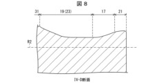
- FIG. 5 is a cross-sectional view of the cutting insert shown in FIG. 4 taken along line IV-E;
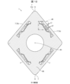
- FIG. 10 is a cross-sectional view of the cutting insert shown in FIG. 9 taken along line IX-A; 11 is an enlarged view of a region A3 shown in FIG. 10;
- FIG. FIG. 10 is a cross-sectional view of the cutting insert shown in FIG. 9 taken along line IX-B; 13 is an enlarged view of a region A4 shown in FIG. 12;
- FIG. 10A and 10B are explanatory diagrams showing deformed shapes of a first cross section of the cutting insert shown in FIG. 9 and a fourth cross section of the cutting insert of the modified example;
- FIG. 2 is an explanatory view schematically showing contact of chips with the rising surface of the cutting insert shown in FIG. 1; It is a perspective view showing a cutting tool of an embodiment. It is the schematic which shows the manufacturing method of the cut workpiece of embodiment.
- the cutting insert 1 of the embodiment (hereinafter also simply referred to as the insert 1) will be described in detail below with reference to the drawings. However, in each drawing referred to below, for convenience of explanation, only main members necessary for explaining the embodiments are shown in a simplified manner. Accordingly, the insert 1 may comprise any components not shown in the figures to which this disclosure refers. Also, the dimensions of the members in each drawing do not faithfully represent the actual dimensions of the constituent members, the dimensional ratios of the respective members, and the like.
- Cutting can be performed by using a cutting tool having the insert 1 of the embodiment.
- Cutting tools include, for example, turning tools and milling tools.
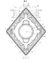
- FIG. 1 the insert 1 of this embodiment has a top surface 3 , a bottom surface 5 opposite the top surface 3 , and a side surface 7 located between the top surface 3 and the bottom surface 5 . .
- the upper surface 3 is polygonal, and specifically, the upper surface 3 is quadrangular.
- the bottom surface 5 may also be polygonal like the top surface 3 .
- the lower surface 5 may be the same size as the upper surface 3 or may be smaller than the upper surface 3 .
- the lower surface 5 may have a similar shape to the upper surface 3 and may be one size smaller than the upper surface 3 .
- the insert 1 has a polygonal plate shape.
- the shape of the insert 1 is not limited to the configuration described above.
- the top surface 3 may not be square, but may be, for example, triangular or hexagonal.
- a virtual plane perpendicular to the central axis R1 and positioned between the upper surface 3 and the lower surface 5 is defined as a reference plane R2 (see FIGS. 5 to 9 and 14).
- the reference plane R2 can be used as a reference for the height when comparing the heights of the parts forming the upper surface 3 . “Approaching the reference surface R2” can be rephrased as “approaching the lower surface 5”. “Separate from the reference surface R2” can be rephrased as “separate from the lower surface 5". "Located near the reference plane R2" can be rephrased as "located near the lower surface 5".
- the upper surface 3 has four corners because it is a quadrangle. Let one of these four corners be the first corner 9 .
- the top surface 3 has a first corner 9 and a first side 11 and a second side 13 extending from the first corner 9 respectively. In other words, the first corner 9 is positioned between the first side 11 and the second side 13 .
- the first corner 9 does not need to be sharp, and the first corner 9 in the insert 1 has an outwardly convex curved shape.
- the radius of curvature of the convex first corner 9 may be constant or may vary.
- the first corner 9 of the insert 1 has an arc shape with a constant radius of curvature when the upper surface 3 is viewed from the front.
- the radius of curvature of the convex first corner 9 is set smaller than the maximum width of the upper surface 3 .
- the first side 11 and the second side 13 on the upper surface 3 need only be approximately linear when visually observed, and need not be strictly linear. That is, the first side 11 and the second side 13 of the upper surface 3 may be, for example, slightly curved convex or concave. In addition, when the first side 11 and the second side 13 are curved, the radius of curvature of the first side 11 and the second side 13 is set larger than the maximum width of the upper surface 3 .
- the side surface 7 located between the upper surface 3 and the lower surface 5 may be connected to the upper surface 3 and the lower surface 5 respectively.
- the side surface 7 since the top surface 3 is polygonal, the side surface 7 has a plurality of surface areas connected to each side and first corner 9 of the top surface 3 .
- the side surface 7 has a first side surface 7a, a second side surface 7b and a corner side surface 7c as these surface regions.
- the first side surface 7a is located along the first side 11 of the upper surface 3.
- the second side surface 7 b is positioned along the second side 13 of the upper surface 3 .
- the corner side 7c is located along the first corner 9 of the top surface 3 .
- the corner side surface 7c is positioned between the first side surface 7a and the second side surface 7b and is adjacent to the first side surface 7a and the second side surface 7b.
- the first side surface 7a and the second side surface 7b may be planar. Further, the corner side surface 7c may have a convex shape.
- a cutting edge 15 may be positioned on at least part of the ridge where the top surface 3 and the side surface 7 intersect.
- the cutting edge 15 is positioned at the first corner 9 , part of the first side 11 and part of the second side 13 of the ridgeline where the top surface 3 and the side surface 7 intersect.
- the cutting edge 15 may be positioned on all of the first side 11 and the second side 13 .
- a portion of the cutting edge 15 located at the first corner 9 is referred to as a corner cutting edge 15c for convenience.
- a portion of the cutting edge 15 located on the first side 11 is referred to as a first cutting edge 15a for convenience.
- a portion of the cutting edge 15 located on the second side 13 is referred to as a second cutting edge 15b for convenience.
- the upper surface 3 has a rake surface 17 and a rising surface (blade wall surface) 19 .
- the rake face 17 is located along the first corner 9, the first side 11 and the second side 13, as shown in FIG. As shown in FIGS. 5 to 9, the rake face 17 approaches the reference plane R2 as it separates from the first corner 9, the first side 11 and the second side 13. As shown in FIG.
- the rising surface 19 is positioned along the rake face 17 as shown in FIG. As shown in FIGS. 5 to 9, the rising surface 19 separates from the reference plane R2 as it separates from the rake face 17. As shown in FIGS. When the chips come into contact with the rising surface 19, the chips are curled, which facilitates the discharge process.
- the boundary between the rake face 17 and the rising face 19 is the lowest point.
- the rake face is the sloped surface that descends to the lowest point closest to the reference surface R2, in other words, the sloped surface that approaches the reference surface R2.
- the top surface 3 has a land surface 21 extending toward the center of the top surface 3 as shown in FIG. may have.
- the land surface 21, as shown in FIGS. 5 to 9 is inclined so as to approach the reference surface R2 as the distance from the first corner 9, the first side 11 and the second side 13 increases.
- the tilt angle is defined as the tilt with respect to the reference surface R2
- the tilt angle of the rake face 19 is larger than the tilt angle of the land surface 21.
- the land surface 21 may be parallel to the reference plane R2 or may be inclined away from the reference plane R2 as the distance from the first corner 9, the first side 11 and the second side 13 increases.
- the upper surface 3 may further have an upper end surface 31 positioned along the rising surface 19 .
- the rising surface 19 will be described below.
- the raised surface 19 near the first side 11 that contributes to the discharge of chips generated by the first cutting edge 15a will be described.
- the description is omitted, the same applies to the rising surface 19 near the second side 13 that contributes to the discharge of chips generated by the second cutting edge 15b.
- the rising surface 19 has a first concave portion 23 , a first convex portion 25 , a second convex portion 27 and a first stepped portion 29 .
- the first concave portion 23 is recessed with respect to the first side 11 .
- the first protrusion 25 is located farther from the first corner 9 than the first recess 23 and protrudes toward the first side 11 .
- the second protrusion 27 is positioned between the first protrusion 25 and the first side 11 and protrudes toward the first side 11 .
- the first stepped portion 29 is positioned between the first convex portion 25 and the second convex portion 27 .
- the first protrusion 25 has a first tip 25A positioned closest to the first side 11 .
- the first tip portion 25A is highlighted by black dots.
- a cross section orthogonal to the first side 11 and including the first tip portion 25A is a first cross section D1.
- FIG. 9 corresponds to the first cross section D1.
- the second protrusion 27 is positioned closer to the reference plane R2 than the first protrusion 25 in the first cross section D1.
- FIG. 14 is an explanatory diagram showing a deformed first section of the insert 1 shown in FIG. 9 and a fourth section of the insert of the modified example.
- the first cross section D1' is a cross section obtained by deforming the first cross section D1.
- the fourth section of the modified insert will be described later.
- chips generated by the first cutting edge 15a contact the second convex portion 27 of the rising surface 19 via the land surface 21 and the rake surface 17.
- the chips do not contact the first stepped portion 29 and reach the first convex portion 25 . Contact. Therefore, the contact area between the rising surface 19 and the chip in the traveling direction is reduced. As a result, it is possible to reduce the contact of the chips with the rising surface 19 over a wide range in the direction in which the chips travel during semi-rough machining.
- Thin chips generated when the feed amount is small also come into contact with the first stepped portion 29 .
- the thin chips come into sliding contact with the second convex portion 27 , the first stepped portion 29 and the first convex portion 25 .
- FIG. 15 is an explanatory view schematically showing contact of chips with the rising surface 19 of the insert 1 shown in FIG.
- the first protrusion 25 and the second protrusion 27 protrude toward the first side 11 . Therefore, the chips K come into contact with the central portions of the first protrusion 25 and the second protrusion 27 and are less likely to come into contact with both end portions of the first protrusion 25 and the second protrusion 27 .
- the chip K has a relatively large thickness generated in medium rough machining, it is difficult to contact.
- the contact area between the chips and the rising surface 19 is reduced even in the width direction of the chips. becomes smaller. As a result, contact of chips with the rising surface 19 over a wide range in the width direction of the chips can be reduced.
- the first concave portion 23 is formed closer to the first corner 9 than the first convex portion 25 is. Therefore, as shown in FIG. 15 , one end in the width direction of the chip K in contact with the first protrusion 25 and the chip K in contact with the second protrusion 27 contacts the first recess 23 . Thereby, the behavior of chips can be stabilized rather than the structure which only the inner side of the width direction of a chip contacts the 1st convex part 25 or the 2nd convex part 27.
- the first convex portion 25 may have a curved shape in the second section D2.
- the second cross section D2 is a cross section parallel to the upper end surface 31 and including the first protrusion 25 in the insert 1, and is a cross-sectional view taken along the line IX-A in the insert 1 shown in FIG. .
- the second convex portion 27 may have a curved shape in the third section D3.
- the third cross section D3 is a cross section parallel to the upper end surface 31 and including the second protrusion 27 in the insert 1, and is a cross-sectional view taken along line IX-B of the insert 1 shown in FIG. . Also in this case, progress of wear of the second convex portion 27 can be suppressed due to the curved shape.
- the first recess 23 has an end 23A closest to the first corner 9, the end 23A being closer to the first side 11 than the first tip 25A. It is good also as composition located near. That is, as shown in FIG. 4, when the distance from the first side 11 to the end portion 23A is L1 and the distance from the first side 11 to the first tip portion 25A is L2, L1 ⁇ L2. In FIG. 4, the end portion 23A is highlighted by a black dot.
- the chips K contact the end portion 23A before the first tip portion 25A.
- the behavior of the chips K can be controlled at the portion 23A.
- the corner cutting edge 15c positioned at the first corner 9 is more fragile and delicate than the first cutting edge 15a. Therefore, chip clogging at the corner cutting edge 15c directly leads to breakage of the corner cutting edge 15c. According to the above configuration, since the behavior of chips near the corner cutting edge 15c can be stably controlled, it is possible to prevent the corner cutting edge 15c from breaking.
- the second convex portion 27 has a second tip portion 27A positioned closest to the first side 11, and the end portion 23A is positioned closer to the first side 11 than the second tip portion 27A.
- L1 ⁇ L3 L1 is the distance from the first side 11 to the end 23A and L3 is the distance from the first side 11 to the second tip 27A.
- the second tip portion 27A is highlighted by black dots.
- the end portion 23A is closer to the first side 11 than the second tip portion 27A. 15c can be made difficult to lose.
- the first convex portion 25 has a first linear portion 25-1
- the second convex portion 27 has a second linear portion 27-1. 2.
- the first convex portion 25 has a first linear portion 25-1 positioned along the upper end surface 31 and a first concave curved portion 25-2 positioned along the first stepped portion 29. ,have.
- the first straight portion 25-1 may be a convex curve.
- the second convex portion 27 has a first convex curved portion 27-1, a second concave curved portion 27-3, and a second straight portion 27-2.
- the first convex curve portion 27-1 is positioned along the first step portion 29.
- a second concave curve portion 27 - 3 is located along the rake face 17 .
- the second straight portion 27-2 is located between the first convex curved portion 27-1 and the second concave curved portion 27-3.
- the first stepped portion 29 is an uneven curve having an inflection point.
- a position near the second convex portion 27 is a convex curve, and a position near the first convex portion 25 is a concave curve.
- the first stepped portion 29 may be straight.
- the first stepped portion 29 may be parallel to the reference plane R2.
- the boundary between the first stepped portion 29 and the first concave curved portion 25-2 may be curved or may have an angle.
- the boundary between the first stepped portion 29 and the first convex curved portion 27-1 may be curved or have an angle.
- the inclination angle ⁇ 1 of the first straight portion 25-1 is larger than the inclination angle ⁇ 2 of the second straight portion 27-2 in the first section D1′.
- the straight portion 25-1 may be shorter than the second straight portion 27-2.
- the first straight portion 25-1 which has a larger inclination angle and a higher braking effect than the second straight portion 27-2, is set short.
- the function of guiding chips by the first protrusion 25 and the second protrusion 27 can be ensured, and the discharge of chips can be improved.
- the inclination angle ⁇ 3 of the first step portion 29 is smaller than the inclination angle ⁇ 1 of the first linear portion 25-1 and the inclination angle ⁇ 2 of the second linear portion 27-2.
- the tilt angle ⁇ 1 is, for example, 30° to 60°
- the tilt angle ⁇ 2 is, for example, 30° to 60°
- the tilt angle ⁇ 3 is, for example, 10° to 25°.
- Thin chips generated when the feed amount is small also contact the second stepped portion 35 and slide against the first recessed portion 23 , the second stepped portion 35 and the second recessed portion 33 .
- the first recess 23 has a third linear portion 23-2 and the second recess 33 has a fourth linear portion 33-1 in the fourth section D4. It is good also as a structure with.
- a fourth cross section D4 is a cross section orthogonal to the first side 11 and crossing the first recess 23 and the second recess 33 . With such a configuration, it is easy to ensure the function of guiding chips by the first recess 23 and the second recess 33 while suppressing the contact area between the chips and the rising surface 19 .
- the first concave portion 23 has a second convex curved portion 23-1, a third concave curved portion 23-3, and a third straight portion 23-2.
- the second convex curve portion 23-1 is positioned along the second stepped portion 35.
- a third concave curve portion 23 - 3 is located along the rake face 17 .
- the third straight portion 23-2 is located between the second convex curved portion 23-1 and the third concave curved portion 23-3.
- the second concave portion 33 has a fourth linear portion 33-1 positioned along the upper end surface 31 and a fourth concave curved portion 33-2 positioned along the second stepped portion 35. As shown in FIG.
- the second stepped portion 35 is an uneven curve having an inflection point.
- a position near the first recess 23 is a convex curve, and a position near the second recess 33 is a concave curve.
- the second stepped portion 35 may be straight.
- the second stepped portion 35 may be parallel to the reference plane R2.
- the boundary between the second stepped portion 35 and the fourth concave curved portion 33-2 may be curved or may have an angle.
- the boundary between the second step portion 35 and the second convex curved portion 23-1 may be curved or have an angle.
- the inclination angle ⁇ 1 of the fourth straight portion 33-1 is larger than the inclination angle ⁇ 2 of the third straight portion 23-2, and the fourth straight portion 33-1 is the third straight portion A configuration shorter than 23-2 may be used.
- the fourth straight portion 33-1 which has a larger angle of inclination and a higher braking effect than the third straight portion 23-2, is set short.
- the function of guiding chips by the first concave portion 23 and the second concave portion 33 can be ensured, and the chip discharging property can be improved.
- the insert 1 has through-holes 37 which are open at the upper surface 3 and the lower surface 5 .
- the through hole 37 may be formed from the center of the upper surface 3 toward the center of the lower surface 5 .
- the through holes 37 may be opened in the surface regions of the side surface 7 that are located on opposite sides of each other.
- the through hole 37 can be used when fixing the insert 1 to a holder of a cutting tool.
- the insert 1 can be fixed to the holder by inserting screws into the through holes 37 and screwing the insert 1 .
- the extending direction of the through-holes 37 may be orthogonal to the upper surface 3 and the lower surface 5, as shown in the example of FIG. Further, since the through hole 37 is formed from the center of the upper surface 3 toward the center of the lower surface 5, the central axis of the through hole 37 coincides with the central axis R1.
- the size of the insert 1 is not particularly limited.
- the maximum width of the upper surface 3 may be set to, for example, approximately 6 mm to 25 mm.
- the height from the upper surface 3 to the lower surface 5 may be set to about 1 mm to 10 mm.
- the height from the upper surface 3 to the lower surface 5 means the length between the upper end of the upper surface 3, that is, the upper end surface 31 and the lower end of the lower surface 5, in the direction parallel to the central axis R1.
- the material of the insert 1 is, for example, cemented carbide or cermet.
- Compositions of cemented carbide include, for example, WC--Co, WC--TiC--Co and WC--TiC--TaC--Co.
- WC, TiC, TaC are hard particles and Co is the binder phase.
- cermet is a sintered composite material that combines metal with ceramic components.
- An example of a cermet is a titanium compound containing titanium carbide (TiC) or titanium nitride (TiN) as a main component.
- TiC titanium carbide
- TiN titanium nitride
- the material of the insert 1 is not limited to the above composition.
- the surface of the insert 1 may be coated with a coating using a chemical vapor deposition (CVD) method or a physical vapor deposition (PVD) method.
- the composition of the coating includes titanium carbide (TiC), titanium nitride (TiN), titanium carbonitride (TiCN), alumina (Al 2 O 3 ), and the like.
- An example cutting tool 101 shown in FIG. 16 has a bar shape extending from a first end toward a second end, and includes a holder 105 having a pocket 103 located on the side of the first end, and the above-described cutting tool located in the pocket 103 .
- the insert 1 is mounted such that the portion used as the cutting edge protrudes from the first end of the holder 105 .
- the first end is usually called the leading end and the second end is called the trailing end.
- the holder 105 has an elongated bar shape.
- One pocket 103 is provided on the first end side of the holder 105 .
- the pocket 103 is a portion where the insert 1 is mounted, and is open to the end face of the holder 105 located on the first end side. At this time, since the pocket 103 is also open to the side surface of the holder 105, the insert 1 can be easily attached.
- the pocket 103 has a seating surface parallel to the lower surface of the holder 105 and a restraining side surface inclined with respect to the seating surface.
- the insert 1 is located in the pocket 103. At this time, the lower surface 5 of the insert 1 may be in direct contact with the pocket 103, or a sheet may be sandwiched between the insert 1 and the pocket 103.
- insert 1 is mounted so that the portion used as the cutting edge protrudes outward from the holder 105 .
- insert 1 is attached to holder 105 by clamping member (lever lock) 39 .
- a member for attaching the insert 1 to the holder 105 is not limited to the clamp member 39, and for example, a fixing screw may be used. That is, by inserting a fixing screw into the through hole 37 of the insert 1 and inserting the tip of the fixing screw into a screw hole (not shown) formed in the pocket 103 and screwing the screw portions together, the insert 1 can be attached to the holder 105. may be attached to the
- Steel, cast iron, or the like can be used as the holder 105 .
- steel with high toughness may be used.
- the present disclosure exemplifies a cutting tool used for so-called turning.
- Turning includes, for example, inner diameter machining, outer diameter machining, and grooving.
- the cutting tool is not limited to those used for turning.
- the insert 1 of the above embodiment may be used for a cutting tool used for milling.
- a method for manufacturing a machined product according to the present disclosure includes the following steps. i.e. (1) a step of rotating the work material 201; (2) a step of contacting the rotating work material 201 with the cutting tool 101 represented by the above embodiment; (3) separating the cutting tool 101 from the work material 201; It has
- the work material 201 is rotated around the axis R3, and the cutting tool 101 is brought relatively closer to the work material 201. 17, the cutting edge of the cutting tool 101 is brought into contact with the work material 201 to cut the work material 201. As shown in FIG. 17, the cutting tool 101 is moved away from the workpiece 201 relatively.
- the cutting tool 101 is brought closer to the work material 201 by moving the cutting tool 101 with the axis R3 fixed and the work material 201 rotated around the axis R3. 17, the workpiece 201 is cut by bringing the cutting edge of the insert 1 into contact with the rotating workpiece 201. In FIG. 17, the cutting tool 101 is moved away from the work material 201 while rotating.
- the cutting tool 101 is brought into contact with the work material 201 or separated from the work material 201 by moving the cutting tool 101 in each step.
- the cutting tool 101 is of course not limited to such a form.
- step (1) the work material 201 may be brought closer to the cutting tool 101 . Also, in the step (3), the work material 201 may be kept away from the cutting tool 101 . In order to continue cutting, the process of keeping the workpiece 201 rotated and bringing the cutting edge of the insert into contact with different portions of the workpiece 201 may be repeated.
- Representative examples of the material of the work material 201 include carbon steel, alloy steel, stainless steel, cast iron, non-ferrous metals, and the like.
Landscapes
- Engineering & Computer Science (AREA)
- Mechanical Engineering (AREA)
- Cutting Tools, Boring Holders, And Turrets (AREA)
Priority Applications (4)
| Application Number | Priority Date | Filing Date | Title |
|---|---|---|---|
| JP2023559490A JP7739448B2 (ja) | 2021-11-09 | 2022-10-11 | 切削インサート、切削工具、及び切削加工物の製造方法 |
| DE112022005354.2T DE112022005354T5 (de) | 2021-11-09 | 2022-10-11 | Schneideinsatz, schneidwerkzeug und verfahren zur herstellung eines maschinell bearbeiteten produkts |
| CN202280071308.8A CN118159375A (zh) | 2021-11-09 | 2022-10-11 | 切削刀片、切削刀具及切削加工物的制造方法 |
| US18/704,925 US20250128335A1 (en) | 2021-11-09 | 2022-10-11 | Cutting insert, cutting tool, and method for manufacturing machined product |
Applications Claiming Priority (2)
| Application Number | Priority Date | Filing Date | Title |
|---|---|---|---|
| JP2021182742 | 2021-11-09 | ||
| JP2021-182742 | 2021-11-09 |
Publications (1)
| Publication Number | Publication Date |
|---|---|
| WO2023084973A1 true WO2023084973A1 (ja) | 2023-05-19 |
Family
ID=86335661
Family Applications (1)
| Application Number | Title | Priority Date | Filing Date |
|---|---|---|---|
| PCT/JP2022/037808 Ceased WO2023084973A1 (ja) | 2021-11-09 | 2022-10-11 | 切削インサート、切削工具、及び切削加工物の製造方法 |
Country Status (5)
| Country | Link |
|---|---|
| US (1) | US20250128335A1 (https=) |
| JP (1) | JP7739448B2 (https=) |
| CN (1) | CN118159375A (https=) |
| DE (1) | DE112022005354T5 (https=) |
| WO (1) | WO2023084973A1 (https=) |
Citations (7)
| Publication number | Priority date | Publication date | Assignee | Title |
|---|---|---|---|---|
| JPH10217008A (ja) * | 1997-01-31 | 1998-08-18 | Kyocera Corp | 切削インサート |
| JP2010532271A (ja) * | 2007-07-05 | 2010-10-07 | テグテック・リミテッド | コーナー凹み部を有する切削インサート |
| WO2017135469A1 (ja) * | 2016-02-05 | 2017-08-10 | 京セラ株式会社 | インサート、切削工具及び切削加工物の製造方法 |
| WO2018042957A1 (ja) * | 2016-08-31 | 2018-03-08 | 住友電工ハードメタル株式会社 | 切削インサート |
| WO2018159499A1 (ja) * | 2017-02-28 | 2018-09-07 | 京セラ株式会社 | 切削インサート、切削工具及び切削加工物の製造方法 |
| WO2019189406A1 (ja) * | 2018-03-27 | 2019-10-03 | 京セラ株式会社 | 切削インサート、切削工具及び切削加工物の製造方法 |
| WO2020017548A1 (ja) * | 2018-07-18 | 2020-01-23 | 京セラ株式会社 | 切削インサート、切削工具及び切削加工物の製造方法 |
Family Cites Families (2)
| Publication number | Priority date | Publication date | Assignee | Title |
|---|---|---|---|---|
| JPH027447A (ja) | 1988-06-24 | 1990-01-11 | Nec Corp | 樹脂封止型半導体装置 |
| DE112008002261B4 (de) * | 2007-08-31 | 2015-06-25 | Kyocera Corporation | Schneideinsatz, Schneidwerkzeug und Schneidverfahren |
-
2022
- 2022-10-11 US US18/704,925 patent/US20250128335A1/en active Pending
- 2022-10-11 WO PCT/JP2022/037808 patent/WO2023084973A1/ja not_active Ceased
- 2022-10-11 DE DE112022005354.2T patent/DE112022005354T5/de active Pending
- 2022-10-11 CN CN202280071308.8A patent/CN118159375A/zh active Pending
- 2022-10-11 JP JP2023559490A patent/JP7739448B2/ja active Active
Patent Citations (7)
| Publication number | Priority date | Publication date | Assignee | Title |
|---|---|---|---|---|
| JPH10217008A (ja) * | 1997-01-31 | 1998-08-18 | Kyocera Corp | 切削インサート |
| JP2010532271A (ja) * | 2007-07-05 | 2010-10-07 | テグテック・リミテッド | コーナー凹み部を有する切削インサート |
| WO2017135469A1 (ja) * | 2016-02-05 | 2017-08-10 | 京セラ株式会社 | インサート、切削工具及び切削加工物の製造方法 |
| WO2018042957A1 (ja) * | 2016-08-31 | 2018-03-08 | 住友電工ハードメタル株式会社 | 切削インサート |
| WO2018159499A1 (ja) * | 2017-02-28 | 2018-09-07 | 京セラ株式会社 | 切削インサート、切削工具及び切削加工物の製造方法 |
| WO2019189406A1 (ja) * | 2018-03-27 | 2019-10-03 | 京セラ株式会社 | 切削インサート、切削工具及び切削加工物の製造方法 |
| WO2020017548A1 (ja) * | 2018-07-18 | 2020-01-23 | 京セラ株式会社 | 切削インサート、切削工具及び切削加工物の製造方法 |
Also Published As
| Publication number | Publication date |
|---|---|
| US20250128335A1 (en) | 2025-04-24 |
| JPWO2023084973A1 (https=) | 2023-05-19 |
| JP7739448B2 (ja) | 2025-09-16 |
| CN118159375A (zh) | 2024-06-07 |
| DE112022005354T5 (de) | 2024-08-22 |
Similar Documents
| Publication | Publication Date | Title |
|---|---|---|
| US10010939B2 (en) | Cutting insert, cutting tool, and method for manufacturing machined product | |
| JP7168655B2 (ja) | 切削インサート、切削工具及び切削加工物の製造方法 | |
| JP6940334B2 (ja) | 切削インサート、切削工具及び切削加工物の製造方法 | |
| JP7442632B2 (ja) | 切削インサート、切削工具、および切削加工物の製造方法 | |
| JP6272457B2 (ja) | 切削インサート、切削工具及び切削加工物の製造方法 | |
| JPWO2020009002A1 (ja) | 切削インサート、切削工具及び切削加工物の製造方法 | |
| US11305358B2 (en) | Cutting insert, cutting tool, and method for manufacturing machined product | |
| CN113613816A (zh) | 切削刀片、车削刀具以及切削加工物的制造方法 | |
| CN110944777B (zh) | 切削刀片、切削工具以及切削加工物的制造方法 | |
| WO2019230987A1 (ja) | 切削インサート、切削工具及び切削加工物の製造方法 | |
| JP7325510B2 (ja) | 切削インサート、切削工具及び切削加工物の製造方法 | |
| JP2019171511A (ja) | 切削インサート、切削工具及び切削加工物の製造方法 | |
| WO2021095520A1 (ja) | 切削インサート、切削工具及び切削加工物の製造方法 | |
| JP7739448B2 (ja) | 切削インサート、切削工具、及び切削加工物の製造方法 | |
| WO2020179538A1 (ja) | 旋削工具及び切削加工物の製造方法 | |
| JP7257413B2 (ja) | 切削インサート、切削工具及び切削加工物の製造方法 | |
| US20230415239A1 (en) | Cutting insert, cutting tool, and method for manufacturing machined product | |
| JP6495681B2 (ja) | 切削インサート、切削工具及び切削加工物の製造方法 | |
| WO2019022016A1 (ja) | 切削インサート、切削工具及び切削加工物の製造方法 | |
| JP7455964B2 (ja) | 切削インサート、切削工具および切削加工物の製造方法 | |
| JP7117389B2 (ja) | 切削インサート、切削工具及び切削加工物の製造方法 | |
| CN115551663B (zh) | 切削刀片、切削刀具以及切削加工物的制造方法 | |
| JP7344376B2 (ja) | 切削インサート、切削工具および切削加工物の製造方法 | |
| JP2018034282A (ja) | 切削インサート、切削工具及び切削加工物の製造方法 | |
| US11628504B2 (en) | Cutting insert, cutting tool, and method for manufacturing machined product |
Legal Events
| Date | Code | Title | Description |
|---|---|---|---|
| 121 | Ep: the epo has been informed by wipo that ep was designated in this application |
Ref document number: 22892473 Country of ref document: EP Kind code of ref document: A1 |
|
| ENP | Entry into the national phase |
Ref document number: 2023559490 Country of ref document: JP Kind code of ref document: A |
|
| WWE | Wipo information: entry into national phase |
Ref document number: 202280071308.8 Country of ref document: CN |
|
| WWE | Wipo information: entry into national phase |
Ref document number: 18704925 Country of ref document: US |
|
| WWE | Wipo information: entry into national phase |
Ref document number: 112022005354 Country of ref document: DE |
|
| 122 | Ep: pct application non-entry in european phase |
Ref document number: 22892473 Country of ref document: EP Kind code of ref document: A1 |
|
| WWP | Wipo information: published in national office |
Ref document number: 18704925 Country of ref document: US |