WO2023074053A1 - 第1コネクタ及びコネクタモジュール - Google Patents
第1コネクタ及びコネクタモジュール Download PDFInfo
- Publication number
- WO2023074053A1 WO2023074053A1 PCT/JP2022/026886 JP2022026886W WO2023074053A1 WO 2023074053 A1 WO2023074053 A1 WO 2023074053A1 JP 2022026886 W JP2022026886 W JP 2022026886W WO 2023074053 A1 WO2023074053 A1 WO 2023074053A1
- Authority
- WO
- WIPO (PCT)
- Prior art keywords
- contact
- connector
- contact portion
- metal member
- insulator
- Prior art date
Links
Images


Classifications
-
- H—ELECTRICITY
- H01—ELECTRIC ELEMENTS
- H01R—ELECTRICALLY-CONDUCTIVE CONNECTIONS; STRUCTURAL ASSOCIATIONS OF A PLURALITY OF MUTUALLY-INSULATED ELECTRICAL CONNECTING ELEMENTS; COUPLING DEVICES; CURRENT COLLECTORS
- H01R13/00—Details of coupling devices of the kinds covered by groups H01R12/70 or H01R24/00 - H01R33/00
- H01R13/648—Protective earth or shield arrangements on coupling devices, e.g. anti-static shielding
- H01R13/658—High frequency shielding arrangements, e.g. against EMI [Electro-Magnetic Interference] or EMP [Electro-Magnetic Pulse]
- H01R13/6591—Specific features or arrangements of connection of shield to conductive members
- H01R13/6597—Specific features or arrangements of connection of shield to conductive members the conductive member being a contact of the connector
-
- H—ELECTRICITY
- H01—ELECTRIC ELEMENTS
- H01R—ELECTRICALLY-CONDUCTIVE CONNECTIONS; STRUCTURAL ASSOCIATIONS OF A PLURALITY OF MUTUALLY-INSULATED ELECTRICAL CONNECTING ELEMENTS; COUPLING DEVICES; CURRENT COLLECTORS
- H01R12/00—Structural associations of a plurality of mutually-insulated electrical connecting elements, specially adapted for printed circuits, e.g. printed circuit boards [PCB], flat or ribbon cables, or like generally planar structures, e.g. terminal strips, terminal blocks; Coupling devices specially adapted for printed circuits, flat or ribbon cables, or like generally planar structures; Terminals specially adapted for contact with, or insertion into, printed circuits, flat or ribbon cables, or like generally planar structures
- H01R12/70—Coupling devices
- H01R12/77—Coupling devices for flexible printed circuits, flat or ribbon cables or like structures
- H01R12/771—Details
- H01R12/775—Ground or shield arrangements
-
- H—ELECTRICITY
- H01—ELECTRIC ELEMENTS
- H01R—ELECTRICALLY-CONDUCTIVE CONNECTIONS; STRUCTURAL ASSOCIATIONS OF A PLURALITY OF MUTUALLY-INSULATED ELECTRICAL CONNECTING ELEMENTS; COUPLING DEVICES; CURRENT COLLECTORS
- H01R13/00—Details of coupling devices of the kinds covered by groups H01R12/70 or H01R24/00 - H01R33/00
- H01R13/648—Protective earth or shield arrangements on coupling devices, e.g. anti-static shielding
- H01R13/658—High frequency shielding arrangements, e.g. against EMI [Electro-Magnetic Interference] or EMP [Electro-Magnetic Pulse]
- H01R13/6581—Shield structure
- H01R13/6582—Shield structure with resilient means for engaging mating connector
- H01R13/6583—Shield structure with resilient means for engaging mating connector with separate conductive resilient members between mating shield members
-
- H—ELECTRICITY
- H01—ELECTRIC ELEMENTS
- H01R—ELECTRICALLY-CONDUCTIVE CONNECTIONS; STRUCTURAL ASSOCIATIONS OF A PLURALITY OF MUTUALLY-INSULATED ELECTRICAL CONNECTING ELEMENTS; COUPLING DEVICES; CURRENT COLLECTORS
- H01R12/00—Structural associations of a plurality of mutually-insulated electrical connecting elements, specially adapted for printed circuits, e.g. printed circuit boards [PCB], flat or ribbon cables, or like generally planar structures, e.g. terminal strips, terminal blocks; Coupling devices specially adapted for printed circuits, flat or ribbon cables, or like generally planar structures; Terminals specially adapted for contact with, or insertion into, printed circuits, flat or ribbon cables, or like generally planar structures
- H01R12/70—Coupling devices
- H01R12/77—Coupling devices for flexible printed circuits, flat or ribbon cables or like structures
- H01R12/79—Coupling devices for flexible printed circuits, flat or ribbon cables or like structures connecting to rigid printed circuits or like structures
Definitions
- the present disclosure relates to first connectors and connector modules.
- a connector for electrically connecting a flexible flat cable (FFC), a flexible printed circuit board (FPC), or the like to a circuit board is also required to be designed for high-speed transmission.
- Patent Literature 1 discloses an electrical connector that enables excellent electromagnetic shielding of signal transmission paths without performing additional operations.
- a first connector includes: A first connector attached to the connection object, the first connector having a plurality of contact wires exposed at the tip of the connection object and a ground part covering part of the contact wires, a first insulator having a holding portion that holds the object to be connected in a state where the tip is accommodated; a first metal member attached to the first insulator; with The first metal member is a first base formed in a plate shape; a first contact portion extending from the first base portion toward the tip end and making contact with the contact line; a second contact portion located on the opposite side of the tip from the first contact portion and in contact with the ground portion; have
- a connector module includes: the first connector; a second connector that mates with the first connector;
- a connector module comprising: The second connector is a second insulator fitted with the first insulator; a first contact attached to the second insulator; with The first contact has a third contact portion that contacts the first metal member.
- a connector module includes: the first connector; a second connector that mates with the first connector;
- a connector module comprising: The second connector is a second insulator fitted with the first insulator; a first contact attached to the second insulator; with The first contact has a third contact portion that contacts the contact line with which the first contact portion contacts.
- FIG. 1 is an external perspective view showing a top view of a connector module according to an embodiment in which a first connector and a second connector holding connection objects are connected to each other;
- FIG. FIG. 2 is an external perspective view showing the first connector of FIG. 1 holding a connection object, viewed from below;
- FIG. 4 is an external perspective view showing a connection object in a state not held by the first connector as viewed from above;
- FIG. 4 is an external perspective view showing a connecting object in a state not held by the first connector as viewed from below;
- 3 is an enlarged view enlarging a portion V surrounded by a dashed line in FIG. 2.
- FIG. It is the external appearance perspective view which showed the 1st metal member single-piece
- FIG. 3 is a cross-sectional view along the VII-VII arrow line in FIG. 2;
- FIG. 3 is a cross-sectional view along the VIII-VIII arrow line in FIG. 2;
- FIG. 3 is a cross-sectional view along the IX-IX arrow line in FIG. 2;
- FIG. 2 is an external perspective view showing the second connector alone in FIG. 1 as viewed from the rear and top;
- FIG. 2 is an external perspective view showing the second connector alone in FIG. 1 as viewed from the front and above;
- FIG. 12 is an exploded perspective view of the second connector unit of FIG. 11;
- FIG. 2 is a cross-sectional view taken along line XIII-XIII in FIG. 1;
- 2 is a cross-sectional view taken along line XIV-XIV in FIG.
- FIG. FIG. 2 is a cross-sectional view taken along the line XV-XV of FIG. 1; It is the external appearance perspective view which showed the 1st metal member simple substance which concerns on a modification by the top view.
- 15 is a cross-sectional view corresponding to FIG. 14, showing a cross-section of a connector module according to a modification; FIG.
- the first connector and connector module according to one embodiment of the present disclosure, it is possible to obtain good transmission characteristics in signal transmission.
- FIG. 1 is an external perspective view of a connector module 1 according to an embodiment in which a first connector 10 holding a connection object 40 and a second connector 50 are connected to each other.
- FIG. 2 is an external perspective view showing the first connector 10 of FIG. 1 holding the connection object 40 as viewed from below. Configurations of a connector module 1 and a first connector 10 according to an embodiment will be mainly described with reference to FIGS. 1 and 2.
- FIG. 1 is an external perspective view of a connector module 1 according to an embodiment in which a first connector 10 holding a connection object 40 and a second connector 50 are connected to
- the connector module 1 has a first connector 10 and a second connector 50 connectable to each other.
- the second connector 50 is mounted on the circuit board CB.
- the circuit board CB may be a rigid board or any other circuit board.
- the second connector 50 electrically connects the connection object 40 inserted into the second connector 50 together with the first connector 10 and the circuit board CB.
- the second connector 50 can insert and remove the connection object 40 via the first connector 10 , and is connected to the connection object 40 in a state where the connection object 40 is inserted.
- the second connector 50 has a second insulator 60, a first contact 70a, a second contact 70b, and a second metal member 80.
- the first contact 70 a , the second contact 70 b and the second metal member 80 are attached to the second insulator 60 .
- the first connector 10 holds a connection object 40.
- the first connector 10 receives the connection object 40 inserted from the front to the rear, and supports both ends of the connection object 40 in the left-right direction, thereby holding the connection object 40 as a whole.
- connection object 40 held by the first connector 10 is, for example, an FFC.
- the connection object 40 is not limited to this, and may be any cable as long as it is electrically connected to the circuit board CB via the first connector 10 and the second connector 50 .
- the connection object 40 may be an FPC.
- the connection object 40 is not limited to cables as described above, and may include any object.
- connection object 40 may include a rigid substrate or any other circuit substrate.
- the first connector 10 can be connected to the second connector 50 while holding the connection target 40 .
- the first connector 10 has a first insulator 20 fitted with the second insulator 60 in a connected state in which the first connector 10 and the second connector 50 are connected to each other.
- the first connector 10 has a first metal member 30 attached to the first insulator 20 .
- connection object 40 contacts the second contact 70b in a fitted state in which the first insulator 20 and the second insulator 60 are fitted to each other.
- the first metal member 30 contacts the first contact 70a in a fitted state in which the first insulator 20 and the second insulator 60 are fitted to each other.
- the second connector 50 is a receptacle connector.
- the first connector 10 is described as a plug connector.
- the second connector 50 in which the first contacts 70a and the second contacts 70b are elastically deformed when the first insulator 20 and the second insulator 60 are fitted to each other will be described as a receptacle connector.
- the first connector 10 holding the connection object 40 in the fitted state will be described as a plug connector.
- the types of the first connector 10 and the second connector 50 are not limited to these.
- the second connector 50 may act as a plug connector and the first connector 10 as a receptacle connector.
- connection object 40 is inserted into the second connector 50 in a direction parallel to the circuit board CB on which the second connector 50 is mounted.
- the connection object 40 is inserted into the second connector 50 along the front-rear direction, for example.
- the object to be connected 40 may be inserted into the second connector 50 in a direction perpendicular to the circuit board CB on which the second connector 50 is mounted.
- the connection object 40 may be inserted into the second connector 50 along the vertical direction.
- the "extending direction of the contact line” used below means the front-back direction as an example.
- the “insertion/removal direction” means, for example, the front-rear direction.
- a direction orthogonal to the extending direction of the contact line” means, for example, a vertical direction.
- the “tip of the connection object” means, for example, the rear tip of the connection object.
- “Withdrawal side” means the front side as an example.
- “Insertion side” means the rear side, by way of example.
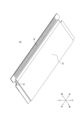
- FIG. 3 is an external perspective view showing the connection object 40 not held by the first connector 10 as viewed from above.
- FIG. 4 is an external perspective view showing the connection object 40 not held by the first connector 10 as viewed from below.
- the configuration of the connection object 40 held by the first connector 10 will be mainly described with reference to FIGS. 3 and 4.
- the object to be connected 40 has a laminated structure formed by bonding a plurality of thin film materials to each other.
- the object to be connected 40 has a reinforcing portion 41 that constitutes a leading end portion in the direction in which the object to be connected 40 extends, that is, the direction in which the object to be connected 40 is inserted and withdrawn, and that is harder than the other portions.
- the object to be connected 40 has a plurality of contact lines 42 that extend linearly along the inserting/removing direction and extend to the tip of the reinforcing portion 41 .
- the contact wire 42 is exposed downward at the tip of the connection object 40 .
- the connection object 40 has a first ground part 43 that covers part of the contact wire 42 on the removal side of the connection object 40 with the lower outermost layer.
- the first ground portion 43 extends in a flat plate shape from the front to the rear and is bent obliquely upward at its tip.
- the connection object 40 has a second ground portion 44 covering substantially the entire contact wire 42 with the uppermost outer layer.
- the second ground portion 44 extends in a flat plate shape from the front to the rear, and is laminated above the reinforcement portion 41 at the tip portion of the second ground portion 44 while bending obliquely upward at the front edge portion of the reinforcement portion 41 . ing.
- the object to be connected 40 has a locked portion 45 in which the central portion is notched inward in the left-right direction at the end edge along the front-rear direction of the tip of the object to be connected 40 including the reinforcing portion 41 .
- the locked portions 45 are formed on both sides in the left-right direction at the distal end portion of the connection object 40 including the reinforcing portion 41 .
- FIG. 5 is an enlarged view of the portion V enclosed by the dashed-dotted line in FIG.
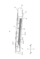
- FIG. 6 is an external perspective view showing the first metal member 30 alone as viewed from above.
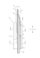
- FIG. 7 is a cross-sectional view taken along line VII--VII in FIG.
- FIG. 8 is a cross-sectional view taken along line VIII-VIII in FIG.
- FIG. 9 is a cross-sectional view taken along line IX-IX in FIG.
- the configuration of the first connector 10 according to one embodiment will be mainly described with reference to FIGS. 2 and 5 to 9.
- FIG. 1 is an enlarged view of the portion V enclosed by the dashed-dotted line in FIG.
- FIG. 6 is an external perspective view showing the first metal member 30 alone as viewed from above.
- FIG. 7 is a cross-sectional view taken along line VII--VII in FIG.
- FIG. 8 is a cross-sectional view taken along line VIII-VIII in FIG.
- FIG. 9 is a cross-section
- the first insulator 20 is a symmetrical box-shaped member injection-molded from an insulating and heat-resistant synthetic resin material.
- the first insulator 20 has four outer walls in the vertical and horizontal directions, and has an outer peripheral wall 21 formed in a rectangular shape as a whole.
- the outer peripheral wall 21 has a ceiling wall 21a, a bottom wall 21b, and a pair of side walls 21c.
- the first insulator 20 has a protruding portion 22 that protrudes from the side wall 21c toward the insertion side of the connection object 40 from the ceiling wall 21a and the bottom wall 21b.
- the first insulator 20 has an insertion portion 23 surrounded by an outer peripheral wall 21 in the vertical and horizontal directions. As shown in FIG. 7 , the first insulator 20 has a holding portion 24 recessed inside the projecting portion 22 . The first insulator 20 has a lock portion 25 that extends from the center portion of the side wall 21c in the front-rear direction to the center portion of the holding portion 24 in the front-rear direction. The locking portion 25 is elastically deformable in the vertical direction. As shown in FIGS. 8 and 9, the first insulator 20 has a mounting portion 26 formed along the upper surface of the bottom wall 21b.
- the first metal member 30 is formed by molding a thin plate of any metal material into the shape shown in FIG. 6 using a progressive die (stamping).
- the first metal member 30 is formed by bending in the plate thickness direction after punching.
- the processing method of the first metal member 30 is not limited to this, and may include only the step of punching, for example.
- the surface of the first metal member 30 is surface-plated with gold, tin, or the like after a base is formed by nickel plating. Plating, including nickel plating and surface layer plating, may be partially applied to required locations.
- the first metal member 30 has a first base portion 31 formed in a plate shape in the front, rear, left, and right directions.
- the first base portion 31 includes a first portion 31a that is formed as a flat plate extending in the front, rear, left, and right directions, and a second portion 31b that is bent obliquely upward from the rear edge of the first portion 31a and extends horizontally again. include.
- the first metal member 30 has a first contact portion 32 extending rearward from the rear edge portion of the first base portion 31, for example, the second portion 31b.
- the first contact portion 32 bends obliquely upward from the rear edge portion of the second portion 31 b and extends horizontally again at the rear end portion of the first contact portion 32 .
- the first contact portion 32 is formed to be wide in the left-right direction from the portion connected to the second portion 31b to the central portion of the portion extending obliquely upward. It is formed to be tapered.
- the first contact portion 32 is notched in the plate thickness direction at the central portion of the portion formed to be wide in the left-right direction.
- the first contact portion 32 is elastically deformable in the vertical direction.
- the first metal member 30 has a second contact portion 33 that is positioned forward of the first contact portion 32 and extends rearward from the rear portion of the first base portion 31, for example, the first portion 31a.
- the second contact portion 33 linearly extends obliquely upward from the rear portion of the first portion 31a and bends upward at the rear end portion of the second contact portion 33.
- the second contact portion 33 is tapered such that the width in the left-right direction continuously decreases from the portion connected to the first portion 31a to the rear end portion.
- the entirety of the second contact portion 33 is accommodated in the portions of the second portion 31b and the first contact portion 32 that are notched in the plate thickness direction.
- a rear end portion of the second contact portion 33 is arranged in a portion of the first contact portion 32 that is cut out in the plate thickness direction.
- the second contact portion 33 is elastically deformable in the vertical direction.
- the first contact portion 32 and the second contact portion 33 are formed in four pairs in total, two pairs on the left side and two pairs on the right side of the first metal member 30 .
- Each set of the first contact portion 32 and the second contact portion 33 is arranged in a state separated from each other along the left-right direction.
- the first contact portion 32 and the second contact portion 33 are linearly arranged along the front-rear direction.
- the first metal member 30 has a plurality of jumping parts 34 arranged at regular intervals along the left-right direction in the front-back direction central part of the first part 31 a of the first base part 31 .
- the jumping portion 34 extends obliquely upward in a straight line from the first portion 31 a and bends upward at the rear end portion of the jumping portion 34 .
- the jumping portion 34 is formed in a tapered shape so that the width in the left-right direction continuously decreases from the portion connected to the first portion 31a to the rear end portion.
- the entire jumping portion 34 is located above the portion of the first portion 31a that is notched in the plate thickness direction.
- the jumping portion 34 is elastically deformable along the vertical direction.
- the jumping portion 34 is not arranged on the same straight line as the set of the first contact portion 32 and the second contact portion 33, but is formed at a laterally offset position.
- the first metal member 30 has locking portions 35 formed on both lateral edge portions of the first portion 31 a of the first base portion 31 .
- the first connector 10 is configured such that the first metal member 30 is inserted from the front side of the first insulator 20 into the first insulator 20 from the front to the rear. be assembled with The first metal member 30 is held by the first insulator 20 while being attached to the attachment portion 26 of the first insulator 20 .
- the function of the first connector 10 when the first metal member 30 is attached to the first insulator 20 will be mainly described below.
- the locking portion 35 is locked to the lateral inner surface of the side wall 21c.
- the rear corners of the left and right edges of the first portion 31a of the first base portion 31 face the forward inner surface of the side wall 21c.
- the first metal member 30 is arranged along the bottom wall 21b of the first connector 10 and substantially all over the lower portion of the first connector 10. As shown in FIG. The first portion 31a of the first base portion 31 contacts the upper surface of the bottom wall 21b. The first contact portion 32 and the second contact portion 33 extend obliquely upward rearward from the rear end of the bottom wall 21b. A rear end portion of the jump portion 34 is positioned inside the insertion portion 23 .
- connection object 40 With the first metal member 30 attached to the first insulator 20 , the connection object 40 is inserted into the insertion portion 23 of the first insulator 20 from the front side of the insertion portion 23 from the front to the rear.
- the function of the first connector 10 when the connection object 40 is inserted into the first insulator 20 and the first connector 10 is attached to the connection object 40 will be mainly described.
- the holding portion 24 accommodates the tip of the connection object 40 and holds the connection object. hold an object 40;
- the locking portion 25 engages with the locked portion 45 .
- the locking portion 25 functions as a stopper for the connection target 40 from the first connector 10 and suppresses unintended removal of the connection target 40 from the first connector 10 .
- the first connector 10 stably holds the connection object 40 .
- the first contact portion 32 extends from the first base portion 31 toward the tip of the connection object 40 and contacts the contact wire 42 .
- the second contact portion 33 is located on the opposite side of the tip of the connection target 40 from the first contact portion 32 and contacts the first ground portion 43 .
- the first contact portion 32 and the second contact portion 33 contact the connection object 40 while being elastically deformed downward.
- the first contact portion 32 and the second contact portion 33 are positioned on the same side with respect to the connection object 40 in the direction orthogonal to the extending direction of the contact line 42 . More specifically, the first contact portion 32 and the second contact portion 33 are orthogonal to both the extending direction of the contact line 42 and the arrangement direction of the first contacts 70a and the second contacts 70b of the second connector 50. They are positioned on the same side with respect to the connection object 40 in the vertical direction.
- the first contact portion 32 contacts a portion of the contact wire 42 adjacent to the boundary R between the contact wire 42 and the first ground portion 43 .
- the second contact portion 33 contacts a portion adjacent to the boundary R in the first ground portion 43 .
- the first contact portion 32 and the second contact portion 33 are arranged linearly along the extending direction of the contact line 42 .
- one first contact portion 32 contacts a plurality of contact lines 42 .
- one first contact portion 32 contacts two contact lines 42 adjacent to each other along the left-right direction.
- the spring portion 34 extends rearward from the first base portion 31 and contacts the first ground portion 43 .
- the jumping portion 34 is located on the opposite side of the tip of the connection object 40 from the first contact portion 32 and the second contact portion 33 .
- the jumping portion 34 contacts the connection object 40 while being elastically deformed downward.
- the jumping portion 34 is located on the same side of the connecting object 40 as the first contact portion 32 and the second contact portion 33 in the direction orthogonal to the extending direction of the contact line 42 .
- the jump part 34 is not arranged linearly along the extending direction of the contact line 42 with respect to the first contact part 32 and the second contact part 33, but is formed at a position shifted in the left-right direction. ing.
- the second portion 31 b of the first base portion 31 extends rearward from the first portion 31 a and contacts the first ground portion 43 .
- the second portion 31 b is located on the opposite side of the tip of the connection target 40 from the first contact portion 32 and the second contact portion 33 .
- the second portion 31 b is located on the same side of the connection object 40 as the first contact portion 32 and the second contact portion 33 in the direction orthogonal to the extending direction of the contact line 42 .
- FIG. 10 is an external perspective view showing the second connector 50 alone in FIG. 1 as viewed from the rear and top.
- FIG. 11 is an external perspective view showing the second connector 50 alone in FIG. 1 as viewed from the front and above.
- 12 is an exploded perspective view of the second connector 50 alone in FIG. 11.
- the second connector 50 is assembled by the following method as an example.
- the first contact 70 a and the second contact 70 b are press-fitted into the second insulator 60 from behind the second insulator 60 .
- the second metal member 80 is press-fitted into the second insulator 60 so as to cover the entirety of the second insulator 60 from above.
- the second connector 50 is mounted on the circuit board CB.
- the second connector 50 electrically connects the connection object 40 and the circuit board CB via the first contacts 70a and the second contacts 70b.
- the second insulator 60 is a symmetrical box-shaped member injection-molded from an insulating and heat-resistant synthetic resin material.
- the second insulator 60 is not limited to this, and may be formed asymmetrically in the left-right direction.
- the second insulator 60 has four outer walls in the vertical and horizontal directions, and has an outer peripheral wall 61 formed in a rectangular shape as a whole.
- the outer peripheral wall 61 has a ceiling wall 61a, a bottom wall 61b, and a pair of side walls 61c.
- the second insulator 60 has a rear wall 62 formed continuously with a ceiling wall 61a and a pair of side walls 61c. As shown in FIGS. 11 and 12 , the second insulator 60 has an insertion portion 63 surrounded by an outer peripheral wall 61 in the vertical and horizontal directions. The front side of the insertion portion 63 is largely opened by the opening of the second insulator 60 . On the other hand, the rear side of the insertion portion 63 is closed by the rear wall 62 .
- the second insulator 60 has a first hole portion 64a penetrating through the ceiling wall 61a from the upper surface of the ceiling wall 61a to the insertion portion 63.
- the first hole portion 64a extends linearly over substantially the entire ceiling wall 61a along the front-rear direction.
- a total of four first holes 64a are formed in the ceiling wall 61a, two on the left side and two on the right side.
- the first holes 64a are arranged so as to be spaced apart from each other along the left-right direction.
- the second insulator 60 has second holes 64b formed at both ends of the ceiling wall 61a in the left-right direction and penetrating the ceiling wall 61a from the upper surface of the ceiling wall 61a to the insertion portion 63.
- a pair of the second hole portions 64b are arranged on both outer sides in the left-right direction with respect to the entire four first hole portions 64a.
- the second hole portion 64b extends linearly over substantially the entire ceiling wall 61a along the front-rear direction.
- the second insulator 60 has a plurality of third holes 64c arranged in the front edge of the ceiling wall 61a while being spaced apart from each other in the left-right direction. As shown in FIG. 10, the second insulator 60 has a plurality of fourth holes 64d arranged in the upper edge of the rear wall 62 while being spaced apart from each other in the left-right direction.
- the second insulator 60 includes a plurality of contact mounting grooves 65 extending in the front-rear direction from the outer surface of the rear wall 62 to the interior of the insertion portion 63 .
- the plurality of contact mounting grooves 65 are arranged in the left-right direction at predetermined intervals.
- the contact mounting groove 65 includes a first contact mounting groove 65a and a second contact mounting groove 65b.
- the first contact mounting grooves 65a are recessed at positions matching the number and mounting positions of the first contacts 70a shown in FIG.
- the second contact mounting grooves 65b are recessed at positions matching the number and mounting positions of the second contacts 70b shown in FIG.
- the first contact 70a is made of, for example, a spring-elastic copper alloy containing phosphor bronze, beryllium copper, or titanium copper, or a thin plate of a Corson copper alloy, which is formed into the shape shown in FIG. 12 using a progressive die (stamping). It is processed.
- the first contact 70a is formed only by punching.
- the processing method of the first contact 70a is not limited to this, and may include, for example, a step of bending in the plate thickness direction after punching.
- the surface of the first contact 70a is surface-layer plated with gold, tin, or the like after a base is formed by nickel plating.
- a total of eight first contacts 70a are arranged in the second connector 50, four on the left side and four on the right side.
- the first contact 70a is formed in a rectangular shape and has a locking portion 71a having a projection on its upper edge.
- the first contact 70a has a mounting portion 72a extending rearward in an L shape from the lower end portion of the locking portion 71a.
- the first contact 70a has a third contact portion 73a that extends forward while being bent from the front end portion of the locking portion 71a.
- the first contact 70a has a sixth contact portion 74a positioned at the rear edge of the locking portion 71a.
- the second contact 70b is made of, for example, a spring-elastic copper alloy containing phosphor bronze, beryllium copper, or titanium copper, or a thin plate of a Corson copper alloy, which is formed into the shape shown in FIG. 12 using a progressive die (stamping). It is processed.
- the second contact 70b is formed only by punching.
- the processing method of the second contact 70b is not limited to this, and may include, for example, a step of bending in the plate thickness direction after punching.
- the surfaces of the second contacts 70b are surface-layer plated with gold, tin, or the like after a base is formed by nickel plating.
- a plurality of second contacts 70b are arranged in the second connector 50 so as to be separated from each other in the left-right direction.
- the second contact 70b is formed in a rectangular shape and has a locking portion 71b having a projection on its upper edge.
- the second contact 70b has a mounting portion 72b extending rearward in an L shape from the lower end portion of the locking portion 71b.
- the second contact 70b has a fourth contact portion 73b that bends and extends forward from the front end portion of the locking portion 71b.
- the second metal member 80 is formed by forming a thin plate of any metal material into the shape shown in FIG. 12 using a progressive die (stamping).
- the second metal member 80 is formed by bending in the plate thickness direction after punching.
- the processing method of the second metal member 80 is not limited to this, and may include, for example, only the step of punching.
- the second metal member 80 has a second base portion 81 that constitutes its upper portion and is formed in a plate shape. As shown in FIG. 10, the second metal member 80 has a third base portion 82 that extends downward while bending from a second base portion 81 . The second metal member 80 has a fifth contact portion 83 linearly extending downward from the third base portion 82 .
- the second metal member 80 has a plurality of first claws 84a extending like a crank from the front edge of the second base 81. As shown in FIG. The plurality of first claw portions 84a are arranged while being spaced apart from each other in the left-right direction. The first claw portion 84 a engages with the third hole portion 64 c of the second insulator 60 while the second metal member 80 is attached to the second insulator 60 .
- the second metal member 80 has a plurality of second claws 84b protruding forward from the lower edge of the third base 82 so as to be folded back.
- the plurality of second claw portions 84b are arranged while being spaced apart from each other in the left-right direction.
- the second claw portion 84b engages with the fourth hole portion 64d of the second insulator 60 shown in FIG. 10 in a state where the second metal member 80 is attached to the second insulator 60.
- the second metal member 80 has a first locking portion 85a that extends downward in a U shape from both lateral end portions of the rear edge portion of the second base portion 81 . With the second metal member 80 attached to the second insulator 60, the first locking portion 85a is locked to the rear wall 62 of the second insulator 60 shown in FIG.
- the second metal member 80 has a second locking portion 85b that extends downward while being bent from the left-right edge portion of the second base portion 81 .
- the second locking portion 85b is locked to the side wall 61c of the second insulator 60 shown in FIG. 11 in a state where the second metal member 80 is attached to the second insulator 60.
- the second metal member 80 has a mounting portion 86 that extends outward in the left-right direction while being bent from the front end of the lower edge portion of the second locking portion 85b.
- the second metal member 80 has a seventh contact portion 87 extending forward from the second base portion 81 .
- the seventh contact portion 87 is bent in a U shape and then extends obliquely downward toward the front.
- Four seventh contact portions 87 are formed in the second metal member 80 .
- the plurality of seventh contact portions 87 are arranged while being spaced apart from each other in the left-right direction.
- the seventh contact portion 87 is elastically deformable along the vertical direction.
- the second metal member 80 has engaging portions 88 that linearly extend obliquely downward from both left and right end portions of the second base portion 81 .
- the engaging portion 88 is elastically deformable in the vertical direction.
- the second connector 50 is mounted on the circuit forming surface formed on the upper surface of the circuit board CB. More specifically, the mounting portion 72a of the first contact 70a is mounted on the solder paste applied to the pattern on the circuit board CB. The mounting portion 72b of the second contact 70b is mounted on the solder paste applied to the pattern on the circuit board CB. The mounting portion 86 of the second metal member 80 is placed on the solder paste applied to the pattern on the circuit board CB. By heating and melting each solder paste in a reflow oven or the like, the mounting portion 72a, the mounting portion 72b, and the mounting portion 86 are soldered to the pattern. As a result, the mounting of the second connector 50 on the circuit board CB is completed. Electronic components other than the second connector 50, such as a CPU (Central Processing Unit), a controller, or a memory, are mounted on the circuit forming surface of the circuit board CB.
- a CPU Central Processing Unit
- controller or a memory
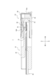
- FIG. 13 is a cross-sectional view taken along line XIII-XIII in FIG.
- FIG. 14 is a cross-sectional view taken along line XIV-XIV in FIG.
- FIG. 15 is a cross-sectional view taken along line XV-XV in FIG.
- the projecting portion 22 of the first insulator 20 is received in the insertion portion 63 of the second insulator 60.
- the engaging portion 88 of the second metal member 80 extends into the insertion portion 63 through the second hole portion 64b of the second insulator 60 .
- the first contact 70 a is attached to the second insulator 60 by engaging with the first contact attachment groove 65 a of the second insulator 60 .
- a third contact portion 73 a of the first contact 70 a contacts the first metal member 30 . More specifically, the third contact portion 73 a contacts the first contact portion 32 of the first metal member 30 . At this time, the third contact portion 73a elastically deforms downward.
- the third contact portion 73 a is located on the same side as the first contact portion 32 with respect to the connection object 40 in the direction orthogonal to the extending direction of the contact line 42 .
- a fifth contact portion 83 of the second metal member 80 extends from a portion of the second metal member 80 including the second base portion 81 and contacts the first contact 70a. As also shown in FIG. 10, the fifth contact portion 83 contacts two first contacts 70a adjacent to each other in the left-right direction.
- a third base portion 82 of the second metal member 80 extends from the second base portion 81 while bending toward the first contact 70 a and along the end surface of the second insulator 60 in the extending direction of the contact line 42 .
- the sixth contact portion 74 a of the first contact 70 a contacts the fifth contact portion 83 of the second metal member 80 .
- the third contact portion 73a and the sixth contact portion 74a are located at both ends of the first contact 70a in the extending direction of the contact wire 42, respectively.
- the first contact 70 a contacts both the first metal member 30 of the first connector 10 and the second metal member 80 of the second connector 50 .
- the first contact 70a is used for ground as an example.
- the second contact 70b is attached to the second insulator 60 by engaging with the second contact attachment groove 65b of the second insulator 60.
- a fourth contact portion 73 b of the second contact 70 b contacts the contact line 42 .
- the fourth contact portion 73b is elastically deformed downward.
- the fourth contact portion 73b is located on the same side as the first contact portion 32 with respect to the connection object 40 in the direction orthogonal to the extending direction of the contact line 42 .
- the second contact 70b is in direct contact with the contact wire 42 of the connection object 40.
- the second contact 70b is used for signals as an example.
- the seventh contact portion 87 of the second metal member 80 is arranged in the first hole portion 64 a of the second insulator 60 .
- the seventh contact portion 87 of the second metal member 80 extends obliquely downward from the second base portion 81 while being bent in a U shape to contact the connection object 40 . More specifically, the seventh contact portion 87 contacts the second ground portion 44 of the connection object 40 . At this time, the seventh contact portion 87 is elastically deformed upward.
- the first connector 10 it is possible to obtain good transmission characteristics in signal transmission.
- the first contact portion 32 of the first metal member 30 contacts the contact line 42 of the connection object 40 and the second contact portion 33 contacts the first ground portion 43 .
- the contact line 42, the first metal member 30, and the first ground portion 43 function stably as one ground.
- a part of the plurality of contact lines 42 stably functions as a ground, thereby suppressing crosstalk between the other plurality of contact lines 42 through which electrical signals are transmitted.
- the first contact portion 32 and the second contact portion 33 are positioned on the same side with respect to the connection object 40 in the direction orthogonal to the extending direction of the contact line 42, so that the first metal member 30 and the connection object It becomes possible to arrange all the contact structures with the object 40 on the same side. For example, by arranging such contact structures only on the lower side of the connection object 40 and not on the upper side, the height of the first connector 10 can be reduced compared to the case where the contact structures are arranged on both sides. It becomes possible. As a result, the height of the entire connector module 1 can be reduced. In addition, the first contact portion 32 and the second contact portion 33 contact the connection object 40 on the same side with respect to the connection object 40 . As a result, crosstalk between the plurality of contact lines 42 through which electrical signals are transmitted is suppressed compared to the case where the contact structures are arranged on both upper and lower sides and are brought into contact with the connection object 40 .
- the first contact portion 32 contacts the portion of the contact line 42 adjacent to the boundary R, and the second contact portion 33 contacts the portion of the first ground portion 43 adjacent to the boundary R, whereby the first contact portion 32 and The distance to the second contact portion 33 can be shortened.
- the contact portion between the first metal member 30 and the contact line 42 and the contact portion between the first metal member 30 and the first ground portion 43 are close to each other. Therefore, the contact line 42, the first metal member 30, and the first ground portion 43 function more stably as one ground. As a result, crosstalk between other contact lines 42 through which electrical signals are transmitted is further suppressed, and transmission characteristics in signal transmission are further improved.
- the first contact portion 32 and the second contact portion 33 By arranging the first contact portion 32 and the second contact portion 33 in a straight line along the extending direction of the contact line 42, compared to the case where the first contact portion 32 and the second contact portion 33 are arranged in a state of being shifted from each other on the same straight line. can shorten the distance between them.
- the contact portion between the first metal member 30 and the contact line 42 and the contact portion between the first metal member 30 and the first ground portion 43 are close to each other. Therefore, the contact line 42, the first metal member 30, and the first ground portion 43 function more stably as one ground. As a result, crosstalk between other contact lines 42 through which electrical signals are transmitted is further suppressed, and transmission characteristics in signal transmission are further improved.
- the first contact portion 32 and the second contact portion 33 are elastically deformable, and by contacting the connection object 40 in an elastically deformed state, contact reliability is improved. For example, even if the connection object 40 vibrates, the first contact portion 32 and the second contact portion 33 are elastically deformed, so that the contact with the connection object 40 is more reliably maintained.
- the connection object 40 when the connection object 40 is inserted into the first connector 10 , it is possible to absorb the vertical thickness tolerance of the connection object 40 . Therefore, workability when inserting and holding the connection object 40 in the first connector 10 is improved.
- the first connector 10 can improve contact reliability with the connection object 40 compared to the case where the first contact portion 32 and the second contact portion 33 are not elastically deformed. As described above, the assembling efficiency between the first connector 10 and the connection object 40 is improved. As a result, productivity is improved when electronic equipment is produced by electrically connecting the connection object 40 and the circuit board CB via the connector module 1 .
- the contact between the first metal member 30 and the contact wires 42 of the object to be connected 40 is made more reliable by having one first contact portion 32 in contact with the plurality of contact wires 42 . Robustness is improved when the first metal member 30 and the contact line 42 contact each other. As a result, the contact line 42, the first metal member 30, and the first ground portion 43 function more stably as one ground. This further suppresses crosstalk between other contact lines 42 through which electrical signals are transmitted.
- the contact line 42, the first metal member 30, and the first ground portion 43 function as one shield.
- the first contact 70a of the second connector 50 Since the first contact 70a of the second connector 50 has the third contact portion 73a that contacts the first metal member 30, the number of ground contact points is increased.
- the first contact 70 a of the second connector 50 can also be electrically connected to the first ground portion 43 via the first metal member 30 . Therefore, the first contact 70a, the contact line 42, the first metal member 30, and the first ground portion 43 function stably as one ground. As a result, crosstalk between other contact lines 42 through which electrical signals are transmitted is further suppressed, and transmission characteristics in signal transmission are further improved.
- the first contact 70 a indirectly contacts the plurality of contact lines 42 via the third contact portion 73 a and the first metal member 30 . This also makes it possible to easily change the horizontal spacing of the first contacts 70a.
- the third contact portion 73a is located on the same side as the first contact portion 32 with respect to the connection object 40 in the direction orthogonal to the extending direction of the contact wire 42.
- the contact structure between the first contact 70a and the first metal member 30 and the contact structure between the first metal member 30 and the connection object 40 can all be arranged on the same side. For example, by arranging these contact structures only on the lower side of the connection object 40 and not on the upper side, the height of the entire connector module 1 can be reduced compared to the case where the contact structures are arranged on both sides. becomes.
- the second contact 70b has a fourth contact portion 73b that contacts the contact wire 42, and the fourth contact portion 73b contacts the first contact portion 32 with respect to the connection object 40 in a direction orthogonal to the extending direction of the contact wire 42. located on the same side as As a result, the contact structure between the second contact 70b and the connection object 40 and the contact structure between the first metal member 30 and the connection object 40 can all be arranged on the same side. For example, by arranging these contact structures only on the lower side of the connection object 40 and not on the upper side, the height of the entire connector module 1 can be reduced compared to the case where the contact structures are arranged on both sides. becomes.
- the fifth contact portion 83 of the second metal member 80 extends from a portion of the second metal member 80 including the second base portion 81 and comes into contact with the first contact 70a, thereby increasing the contact points as ground.
- the second metal member 80 can also be electrically connected to the first ground portion 43 via the first contact 70 a and the first metal member 30 . Therefore, the second metal member 80, the first contact 70a, the contact line 42, the first metal member 30, and the first ground portion 43 function stably as one ground. As a result, crosstalk between other contact lines 42 through which electrical signals are transmitted is further suppressed, and transmission characteristics in signal transmission are further improved.
- the second metal member 80 is press-fitted into the second insulator 60 so as to cover the entire second insulator 60 from above, thereby suppressing the outflow and inflow of noise for electrical signals.
- electromagnetic noise generated from the electrical signal transmitted by the second contact 70b is suppressed from flowing out of the second connector 50 .
- electromagnetic noise generated from other electronic components arranged on the circuit board CB is suppressed from flowing into the second connector 50 .
- a fifth contact portion 83 extends from the third base portion 82 along the end surface of the second insulator 60 in the extending direction of the contact wire 42 while bending from the second base portion 81 toward the first contact 70a.
- the robustness as the strength of the contact portion is improved. Therefore, the second metal member 80 and the first contact 70 a can stably contact each other through the fifth contact portion 83 .
- the second metal member 80, the first contact 70a, the contact line 42, the first metal member 30, and the first ground portion 43 function more stably as one ground. This further suppresses crosstalk between a plurality of other contact lines 42 through which electrical signals are transmitted, further improving transmission characteristics in signal transmission.
- the third contact portion 73a and the sixth contact portion 74a are located at both ends of the first contact 70a in the extending direction of the contact wire 42, respectively.
- This enables stable contact of the first contacts 70 a with both the first metal member 30 of the first connector 10 and the second metal member 80 of the second connector 50 . Therefore, the first metal member 30 and the second metal member 80 can be stably electrically connected to each other through the first contact 70a.
- the second metal member 80, the first contact 70a, the contact line 42, the first metal member 30, and the first ground portion 43 function more stably as one ground. This further suppresses crosstalk between a plurality of other contact lines 42 through which electrical signals are transmitted, further improving transmission characteristics in signal transmission.
- the seventh contact portion 87 of the second metal member 80 extends from the second base portion 81 and comes into contact with the connection object 40, thereby increasing the contact points as the ground.
- the second metal member 80 is electrically connected to the first ground portion 43 of the connection object 40 through the fifth contact portion 83 and the second ground portion of the connection object 40 through the seventh contact portion 87 . 44 are also electrically connected. Therefore, the second ground portion 44 can also be electrically connected to the first ground portion 43 via the second metal member 80 , the first contact 70 a and the first metal member 30 .
- the second ground portion 44, the second metal member 80, the first contact 70a, the contact line 42, the first metal member 30, and the first ground portion 43 function stably as one ground.
- crosstalk between other contact lines 42 through which electrical signals are transmitted is further suppressed, and transmission characteristics in signal transmission are further improved.
- the contact reliability is improved because the seventh contact portion 87 is elastically deformable. For example, even if the connection object 40 vibrates, the seventh contact portion 87 is elastically deformed, so that the contact with the connection object 40 is more reliably maintained.
- the vertical thickness tolerance of the connection object 40 can be absorbed. Therefore, workability when inserting the connection object 40 held by the first connector 10 into the second connector 50 is improved.
- the second connector 50 can hold the connection object 40 more stably than when the seventh contact portion 87 is not elastically deformed.
- the second connector 50 can also improve contact reliability with the connection target 40 . As described above, the ease of assembly between the second connector 50 and the object to be connected 40 is improved. As a result, productivity is improved when electronic equipment is produced by electrically connecting the connection object 40 and the circuit board CB via the connector module 1 .
- each component described above are not limited to the contents shown in the above description and drawings.
- the shape, arrangement, orientation, number, and the like of each component may be arbitrarily configured as long as the function can be realized.
- the method of assembling the first connector 10 described above is not limited to the contents of the above description.
- the first connector 10 may be assembled by any method as long as it can be assembled so that each function can be exhibited.
- the first metal member 30 may be integrally formed with the first insulator 20 by insert molding instead of press fitting.
- the method of assembling the second connector 50 described above is not limited to the contents of the above description. Any method may be used for assembling the second connector 50 as long as it can be assembled so that each function can be exhibited.
- at least one of the first contact 70a, the second contact 70b, and the second metal member 80 may be integrally formed with the second insulator 60 by insert molding instead of press fitting.
- first contact portion 32 and the second contact portion 33 are positioned on the same side with respect to the object to be connected 40 in the direction perpendicular to the extending direction of the contact line 42. Not limited. The first contact portion 32 and the second contact portion 33 may be positioned on different sides of the connection object 40 .
- the first contact portion 32 contacts the portion of the contact line 42 adjacent to the boundary R
- the second contact portion 33 contacts the portion of the first ground portion 43 adjacent to the boundary R. It is not limited to this.
- the first contact portion 32 and the second contact portion 33 may contact arbitrary portions of the contact line 42 and the first ground portion 43, respectively.
- first contact portion 32 and the second contact portion 33 are arranged linearly along the extending direction of the contact line 42, but the present invention is not limited to this.
- the first contact portion 32 and the second contact portion 33 may be arranged not on the same straight line but on different straight lines along the extending direction of the contact line 42 .
- both the first contact portion 32 and the second contact portion 33 are elastically deformable, and are in contact with the connection object 40 in an elastically deformed state, but the present invention is not limited to this. Either one of the first contact portion 32 and the second contact portion 33 may be elastically deformable, or neither of them may be elastically deformable.
- one first contact portion 32 contacts two contact lines 42 adjacent to each other, but the present invention is not limited to this.
- One first contact portion 32 may contact three or more contact lines 42 or may contact only one contact line 42 .
- the first contact portion 32 and the second contact portion 33 are formed in two pairs on the left side and two pairs on the right side of the first metal member 30, for a total of four pairs. but not limited to this.
- Each of the first contact portions 32 and the second contact portions 33 may be formed in an arbitrary number at arbitrary positions different from the positions shown in FIG.
- the present invention is not limited to this.
- the first contact 70 a may contact, for example, the contact wire 42 of the connection object 40 without contacting the first metal member 30 .
- the first contact 70a may be used for signals instead of for ground.
- the third contact portion 73a is positioned on the same side as the first contact portion 32 with respect to the connection object 40 in the direction orthogonal to the extending direction of the contact line 42, but the present invention is not limited to this. .
- the first contact portion 32 and the third contact portion 73 a may be positioned on different sides of the connection object 40 .
- the fourth contact portion 73b is positioned on the same side as the first contact portion 32 with respect to the connection object 40 in the direction perpendicular to the extending direction of the contact line 42, but the present invention is not limited to this. .
- the first contact portion 32 and the fourth contact portion 73 b may be positioned on different sides of the connection object 40 .
- the second metal member 80 has the fifth contact portion 83 extending from a portion of the second metal member 80 including the second base portion 81 to contact the first contact 70a. is not limited to The second metal member 80 does not have to come into contact with the first contact 70a.
- the fifth contact portion 83 contacts two first contacts 70a adjacent to each other in the left-right direction, the present invention is not limited to this.
- the fifth contact portion 83 may contact one or more than three first contacts 70a.
- the fifth contact portion 83 of the second metal member 80 extends from the third base portion 82 in the above embodiment, it is not limited to this.
- the fifth contact portion 83 may directly extend from the second base portion 81 .
- the third contact portion 73a and the sixth contact portion 74a are positioned at both ends of the contact wire 42 in the extending direction of the first contact 70a, but the present invention is not limited to this.
- the third contact portion 73a and the sixth contact portion 74a may be formed at arbitrary positions on the first contact 70a.
- the second metal member 80 has the elastically deformable seventh contact portion 87 that extends from the second base portion 81 and contacts the connection object 40, but the present invention is not limited to this.
- the seventh contact portion 87 may not be elastically deformable.
- the second metal member 80 does not have the seventh contact portion 87 and does not need to contact the connection object 40 .
- first contacts 70a are arranged between the plurality of second contacts 70b, but the present invention is not limited to this.
- the first contacts 70a and the second contacts 70b may be arranged arbitrarily.
- one first contact 70a may be arranged between the plurality of second contacts 70b, or the first contacts 70a and the second contacts 70b may be arranged alternately.
- FIG. 16 is an external perspective view showing a single first metal member 30 according to a modification as viewed from above. Referring to FIG. 16, the configuration of the first metal member 30 according to the modification will be mainly described with respect to the points different from FIG.
- the first contact part 32 does not have to be notched in the plate thickness direction at the central part of the part formed to be wide in the left-right direction.
- the longitudinal length of the rear end of the horizontally extending first contact portion 32 may be shorter than the first contact portion 32 of the first metal member 30 in FIG.
- the second contact portion 33 may be located in the central portion of the portion of the first contact portion 32 formed to be wide in the left-right direction, and may be formed as a convex portion protruding from the surface of the first contact portion 32 .
- the second contact portion 33 may protrude from the surface of the first contact portion 32 so as to have a circular shape when viewed from above.
- FIG. 17 is a cross-sectional view corresponding to FIG. 14, showing a cross-section of the connector module 1 according to the modification.
- the third contact portion 73a of the first contact 70a contacts the first metal member 30 in the above embodiment, the present invention is not limited to this.
- the third contact portion 73a of the first contact 70a may contact the contact line 42 with which the first contact portion 32 contacts.
- the connector module 1 can suppress the first contacts 70a from being greatly deformed or bent, and can suppress the occurrence of buckling of the first contacts 70a.
- the tip of the first contact portion 32 of the first metal member 30 is positioned so as to be the first contact 70a. It is possible to suppress curling of the first metal member 30 caused by contact with the third contact portion 73a.
- the first connector 10 or connector module 1 as described above is mounted on an electronic device.
- Electronic devices include, for example, personal computers, game machines, copiers, printers, facsimiles, and any information devices such as multifunction devices.
- Electronic equipment includes any audiovisual equipment such as LCD televisions, recorders, cameras, and headphones.
- the electronic device may include any vehicle-mounted device such as a camera, radar, drive recorder, and engine control unit.
- the electronic equipment may include any in-vehicle equipment used in in-vehicle systems such as, for example, car navigation systems, advanced driver assistance systems, and security systems.
- electronic equipment may include any industrial equipment.
- the reliability of the electronic device as a product is improved due to the good transmission characteristics in signal transmission of the first connector 10 or the connector module 1 described above.
- Connector Module 10 First Connector 20 First Insulator 21 Peripheral Wall 21a Ceiling Wall 21b Bottom Wall 21c Side Wall 22 Projecting Portion 23 Inserting Portion 24 Holding Portion 25 Locking Portion 26 Mounting Portion 30 First Metal Member 31 First Base Portion 31a First Part 31b Second portion 32 First contact portion 33 Second contact portion 34 Jumping portion 35 Locking portion 40 Connection object 41 Reinforcement portion 42 Contact wire 43 First ground portion 44 Second ground portion 45 Locked portion 50 Second connector 60 Second insulator 61 Peripheral wall 61a Ceiling wall 61b Bottom wall 61c Side wall 62 Rear wall 63 Insert portion 64a First hole 64b Second hole 64c Third hole 64d Fourth hole 65 Contact mounting groove 65a First contact mounting groove 65b Second contact mounting groove 70a First contact 71a Locking portion 72a Mounting portion 73a Third contact portion 74a Sixth contact portion 70b Second contact 71b Locking portion 72b Mounting portion 73b Fourth contact portion 80 Second metal member 81 Second base portion 82 Third base portion 83 Fifth contact portion 84a First
Abstract
本開示に係る第1コネクタ10は、接続対象物40の先端で露出する複数の接触線42と接触線42の一部を覆うグランド部43とを有する接続対象物40に取り付けられる第1コネクタ10であって、先端を収容した状態で接続対象物40を保持する保持部24を有する第1インシュレータ20と、第1インシュレータ20に取り付けられている第1金属部材30と、を備え、第1金属部材30は、板状に形成されている第1基部31と、第1基部31から先端に向けて延出し、接触線42に接触する第1接触部32と、第1接触部32よりも先端の反対側に位置し、グランド部43に接触する第2接触部33と、を有する。
Description
本出願は、2021年10月29日に日本国に特許出願された特願2021-178123号の優先権を主張するものであり、この出願の開示全体をここに参照のために取り込む。
本開示は、第1コネクタ及びコネクタモジュールに関する。
近年、例えばPC(Personal Computer)などを含む情報処理機器、産業機器、及び車載機器などを含む電子機器において、信号の伝送速度の高速化が進んでいる。フレキシブルフラットケーブル(FFC)及びフレキシブルプリント回路基板(FPC)などを回路基板と電気的に接続するコネクタにおいても高速伝送に対応した設計が要求される。
例えば、特許文献1には、付加的な操作を行うことなく、信号伝送経路の電磁遮蔽を良好に行うことを可能とする電気コネクタが開示されている。
本開示の一実施形態に係る第1コネクタは、
接続対象物の先端で露出する複数の接触線と前記接触線の一部を覆うグランド部とを有する前記接続対象物に取り付けられる第1コネクタであって、
前記先端を収容した状態で前記接続対象物を保持する保持部を有する第1インシュレータと、
前記第1インシュレータに取り付けられている第1金属部材と、
を備え、
前記第1金属部材は、
板状に形成されている第1基部と、
前記第1基部から前記先端に向けて延出し、前記接触線に接触する第1接触部と、
前記第1接触部よりも前記先端の反対側に位置し、前記グランド部に接触する第2接触部と、
を有する。
接続対象物の先端で露出する複数の接触線と前記接触線の一部を覆うグランド部とを有する前記接続対象物に取り付けられる第1コネクタであって、
前記先端を収容した状態で前記接続対象物を保持する保持部を有する第1インシュレータと、
前記第1インシュレータに取り付けられている第1金属部材と、
を備え、
前記第1金属部材は、
板状に形成されている第1基部と、
前記第1基部から前記先端に向けて延出し、前記接触線に接触する第1接触部と、
前記第1接触部よりも前記先端の反対側に位置し、前記グランド部に接触する第2接触部と、
を有する。
本開示の一実施形態に係るコネクタモジュールは、
上記の第1コネクタと、
前記第1コネクタと嵌合する第2コネクタと、
を備えるコネクタモジュールであって、
前記第2コネクタは、
前記第1インシュレータと嵌合する第2インシュレータと、
前記第2インシュレータに取り付けられている第1コンタクトと、
を備え、
前記第1コンタクトは、前記第1金属部材に接触する第3接触部を有する。
上記の第1コネクタと、
前記第1コネクタと嵌合する第2コネクタと、
を備えるコネクタモジュールであって、
前記第2コネクタは、
前記第1インシュレータと嵌合する第2インシュレータと、
前記第2インシュレータに取り付けられている第1コンタクトと、
を備え、
前記第1コンタクトは、前記第1金属部材に接触する第3接触部を有する。
本開示の一実施形態に係るコネクタモジュールは、
上記の第1コネクタと、
前記第1コネクタと嵌合する第2コネクタと、
を備えるコネクタモジュールであって、
前記第2コネクタは、
前記第1インシュレータと嵌合する第2インシュレータと、
前記第2インシュレータに取り付けられている第1コンタクトと、
を備え、
前記第1コンタクトは、前記第1接触部が接触する前記接触線に接触する第3接触部を有する。
上記の第1コネクタと、
前記第1コネクタと嵌合する第2コネクタと、
を備えるコネクタモジュールであって、
前記第2コネクタは、
前記第1インシュレータと嵌合する第2インシュレータと、
前記第2インシュレータに取り付けられている第1コンタクトと、
を備え、
前記第1コンタクトは、前記第1接触部が接触する前記接触線に接触する第3接触部を有する。
特許文献1に記載の電気コネクタでは、例えばUSB(Universal Serial Bus)4.0などの高速伝送用の規格における、クロストークの抑制などを含む信号伝送における伝送特性の向上については十分に考慮されていなかった。
本開示の一実施形態に係る第1コネクタ及びコネクタモジュールによれば、信号伝送における良好な伝送特性を得ることが可能である。
以下、添付図面を参照しながら本開示の一実施形態について詳細に説明する。以下の説明中の前後、左右、及び上下の方向は、図中の矢印の方向を基準とする。各矢印の方向は、異なる図面同士で互いに整合している。図面によっては、簡便な図示を目的として、後述する回路基板CBの図示を省略する。
図1は、接続対象物40を保持する第1コネクタ10と第2コネクタ50とが互いに接続されている状態の一実施形態に係るコネクタモジュール1を上面視で示した外観斜視図である。図2は、接続対象物40を保持する図1の第1コネクタ10を下面視で示した外観斜視図である。図1及び図2を参照しながら、一実施形態に係るコネクタモジュール1及び第1コネクタ10の構成について主に説明する。
コネクタモジュール1は、互いに接続可能な第1コネクタ10及び第2コネクタ50を有する。
一実施形態に係る第2コネクタ50は、回路基板CBに実装されている。回路基板CBは、リジッド基板であってよいし、又はそれ以外の任意の回路基板であってもよい。第2コネクタ50は、第1コネクタ10と共に第2コネクタ50に挿入された接続対象物40と回路基板CBとを電気的に接続する。第2コネクタ50は、第1コネクタ10を介して接続対象物40を挿抜可能であり、接続対象物40の挿入状態で接続対象物40と接続される。
第2コネクタ50は、第2インシュレータ60と、第1コンタクト70aと、第2コンタクト70bと、第2金属部材80と、を有する。第1コンタクト70a、第2コンタクト70b、及び第2金属部材80は、第2インシュレータ60に取り付けられている。
第1コネクタ10は、接続対象物40を保持している。例えば、第1コネクタ10は、前方から後方に向けて挿入される接続対象物40を受け入れて、接続対象物40の左右方向の両端部を支持することで接続対象物40全体を保持する。
第1コネクタ10によって保持されている接続対象物40は、一例として、FFCである。しかしながら、これに限定されず、接続対象物40は、第1コネクタ10及び第2コネクタ50を介して回路基板CBと電気的に接続されるものであれば、任意のケーブルであってよい。例えば、接続対象物40は、FPCであってもよい。接続対象物40は、以上のようなケーブルに限定されず、任意の対象物を含んでもよい。例えば、接続対象物40は、リジッド基板又はそれ以外の任意の回路基板を含んでもよい。
第1コネクタ10は、接続対象物40を保持した状態で第2コネクタ50と接続可能である。第1コネクタ10は、第1コネクタ10と第2コネクタ50とが互いに接続する接続状態で第2インシュレータ60と嵌合する第1インシュレータ20を有する。第1コネクタ10は、第1インシュレータ20に取り付けられている第1金属部材30を有する。
接続対象物40は、第1インシュレータ20と第2インシュレータ60とが互いに嵌合する嵌合状態で第2コンタクト70bに接触する。第1金属部材30は、第1インシュレータ20と第2インシュレータ60とが互いに嵌合する嵌合状態で第1コンタクト70aに接触する。
以下では、例えば、一実施形態に係る第2コネクタ50はリセプタクルコネクタであるとして説明する。例えば、第1コネクタ10はプラグコネクタであるとして説明する。第1インシュレータ20と第2インシュレータ60とが互いに嵌合する嵌合状態において、第1コンタクト70a及び第2コンタクト70bが弾性変形する第2コネクタ50をリセプタクルコネクタとして説明する。嵌合状態において、接続対象物40を保持している第1コネクタ10をプラグコネクタとして説明する。第1コネクタ10及び第2コネクタ50の種類は、これらに限定されない。例えば、第2コネクタ50がプラグコネクタの役割を果たし、第1コネクタ10がリセプタクルコネクタの役割を果たしてもよい。
以下では、接続対象物40は、第2コネクタ50が実装されている回路基板CBに対して平行方向に第2コネクタ50に挿入されるとして説明する。接続対象物40は、一例として前後方向に沿って第2コネクタ50に挿入される。これに限定されず、接続対象物40は、第2コネクタ50が実装されている回路基板CBに対して直交方向に第2コネクタ50に挿入されてもよい。接続対象物40は、上下方向に沿って第2コネクタ50に挿入されてもよい。
以下で使用する「接触線の延在方向」は、一例として前後方向を意味する。「挿抜方向」は、一例として前後方向を意味する。「接触線の延在方向と直交する方向」は、一例として上下方向を意味する。「接続対象物の先端」は、一例として接続対象物における後側の先端を意味する。「抜去側」は、一例として前側を意味する。「挿入側」は、一例として後側を意味する。
図3は、第1コネクタ10に保持されていない状態の接続対象物40を上面視で示した外観斜視図である。図4は、第1コネクタ10に保持されていない状態の接続対象物40を下面視で示した外観斜視図である。図3及び図4を参照しながら、第1コネクタ10に保持される接続対象物40の構成について主に説明する。
接続対象物40は、複数の薄膜材を互いに接着して構成した積層構造を有する。接続対象物40は、接続対象物40の延長方向、すなわち接続対象物40を挿抜する挿抜方向の先端部を構成しかつその他の部分に比べて硬い補強部41を有する。接続対象物40は、挿抜方向に沿って直線的に延びかつ補強部41の先端まで延びる複数の接触線42を有する。接触線42は、接続対象物40の先端で下方に向けて露出する。
接続対象物40は、接続対象物40の抜去側で接触線42の一部を下側の最外層にて覆う第1グランド部43を有する。第1グランド部43は、前方から後方に向けて平板状に延在し、その先端において斜め上方に折れている。接続対象物40は、接触線42の略全体を上側の最外層にて覆う第2グランド部44を有する。第2グランド部44は、前方から後方に向けて平板状に延在し、補強部41の前端縁部において斜め上方に折れながら第2グランド部44の先端部において補強部41の上方に積層されている。
接続対象物40は、補強部41を含む接続対象物40の先端部の前後方向に沿った端縁部において、中央部を左右方向の内側に向けて切り欠いた被ロック部45を有する。被ロック部45は、補強部41を含む接続対象物40の先端部において左右方向の両側に形成されている。
図5は、図2の一点鎖線囲み部Vを拡大した拡大図である。図6は、第1金属部材30単体を上面視で示した外観斜視図である。図7は、図2のVII-VII矢線に沿う断面図である。図8は、図2のVIII-VIII矢線に沿う断面図である。図9は、図2のIX-IX矢線に沿う断面図である。図2、及び図5乃至図9を参照しながら、一実施形態に係る第1コネクタ10の構成について主に説明する。
第1インシュレータ20は、絶縁性かつ耐熱性の合成樹脂材料を射出成形した左右対称の箱形の部材である。第1インシュレータ20は、上下左右方向の4つの外壁を有し、全体として矩形状に形成されている外周壁21を有する。外周壁21は、天井壁21aと、底壁21bと、一対の側壁21cと、を有する。図5に示すとおり、第1インシュレータ20は、側壁21cから、天井壁21a及び底壁21bよりも接続対象物40の挿入側に突出している突出部22を有する。
図7乃至図9に示すとおり、第1インシュレータ20は、外周壁21によって上下左右方向を囲まれている挿入部23を有する。図7に示すとおり、第1インシュレータ20は、突出部22の内部に凹設されている保持部24を有する。第1インシュレータ20は、側壁21cの前後方向の中央部から保持部24の前後方向の中央部に至るまで延出するロック部25を有する。ロック部25は、上下方向に沿って弾性変形可能である。図8及び図9に示すとおり、第1インシュレータ20は、底壁21bの上面に沿って形成されている取付部26を有する。
第1金属部材30は、任意の金属材料の薄板を順送金型(スタンピング)を用いて図6に示す形状に成形加工したものである。第1金属部材30は、抜き加工を行った後に板厚方向に屈曲させることで形成されている。第1金属部材30の加工方法はこれに限定されず、例えば抜き加工の工程のみを含んでもよい。第1金属部材30の表面には、ニッケルめっきで下地を形成した後に、金又は錫などによる表層めっきが施されている。ニッケルめっき及び表層めっきを含むめっきは必要な個所に部分的に施されていてもよい。
第1金属部材30は、前後左右方向に板状に形成されている第1基部31を有する。第1基部31は、前後左右方向に広がる平板として形成されている第1部分31aと、第1部分31aの後縁部から斜め上方に折れ曲がって再度水平に延在する第2部分31bと、を含む。
第1金属部材30は、第1基部31、例えば第2部分31bの後縁部から後方に向けて延出する第1接触部32を有する。第1接触部32は、第2部分31bの後縁部から斜め上方に折れ曲がり、第1接触部32の後端部において再度水平に延在する。第1接触部32は、第2部分31bに接続されている部分から斜め上方に延出している部分の中央部に至るまで左右方向に幅広に形成されており、当該中央部から先端に向けて先細りとなるように形成されている。第1接触部32は、左右方向に幅広に形成されている部分の中央部において板厚方向に切り欠かれている。第1接触部32は、上下方向に沿って弾性変形可能である。
第1金属部材30は、第1接触部32よりも前方に位置し、第1基部31、例えば第1部分31aの後部から後方に向けて延出する第2接触部33を有する。図8にも示すとおり、第2接触部33は、第1部分31aの後部から斜め上方に直線状に延出し、第2接触部33の後端部において上方に向けて屈曲する。第2接触部33は、第1部分31aに接続されている部分から後端部に至るまで左右方向の幅が連続的に減少するようにテーパ状に形成されている。第2接触部33の全体は、第2部分31b及び第1接触部32において板厚方向に切り欠かれている部分に収まる。第2接触部33の後端部は、第1接触部32において板厚方向に切り欠かれている部分に配置されている。第2接触部33は、上下方向に沿って弾性変形可能である。
第1接触部32及び第2接触部33は、第1金属部材30において左側に2組、右側に2組で合計4組形成されている。第1接触部32及び第2接触部33の各組は、左右方向に沿って互いに離間した状態で配列されている。第1接触部32と第2接触部33とは、前後方向に沿って直線状に配置されている。
第1金属部材30は、第1基部31の第1部分31aの前後方向の中央部において左右方向に沿って一定間隔で配列されている複数の跳上部34を有する。跳上部34は、第1部分31aから斜め上方に直線状に延出し、跳上部34の後端部において上方に向けて屈曲する。跳上部34は、第1部分31aに接続されている部分から後端部に至るまで左右方向の幅が連続的に減少するようにテーパ状に形成されている。跳上部34の全体は、第1部分31aにおいて板厚方向に切り欠かれている部分の上方に位置する。跳上部34は、上下方向に沿って弾性変形可能である。跳上部34は、第1接触部32及び第2接触部33の組と同一直線上に配置されておらず、左右方向にずれた位置に形成されている。
第1金属部材30は、第1基部31の第1部分31aの左右方向の両端縁部に形成されている係止部35を有する。
図2、図5、及び図7乃至図9に示すとおり、第1コネクタ10は、第1金属部材30が前方から後方に向けて第1インシュレータ20の前側から第1インシュレータ20に挿入されることで組み立てられる。第1金属部材30は、第1インシュレータ20の取付部26に取り付けられた状態で第1インシュレータ20に保持されている。
以下では、第1金属部材30が第1インシュレータ20に取り付けられたときの第1コネクタ10の機能について主に説明する。
第1金属部材30が第1インシュレータ20に取り付けられると、係止部35は、側壁21cの左右方向の内面に係止する。第1基部31の第1部分31aの左右方向の両端縁部における後側の角部は、側壁21cにおいて前方を向く内面と対向する。
図8及び図9に示すとおり、第1金属部材30は、第1コネクタ10の底壁21bに沿って第1コネクタ10の下部の略全体に配置されている。第1基部31の第1部分31aは、底壁21bの上面に接触する。第1接触部32及び第2接触部33は、底壁21bの後端から後方に向けて斜め上方に延出する。跳上部34の後端部は、挿入部23の内部に位置する。
接続対象物40は、第1金属部材30が第1インシュレータ20に取り付けられている状態で、前方から後方に向けて第1インシュレータ20の挿入部23の前側から挿入部23に挿入される。以下では、接続対象物40が第1インシュレータ20に挿入され、第1コネクタ10が接続対象物40に取り付けられたときの第1コネクタ10の機能について主に説明する。
図7に示すとおり、接続対象物40が挿入部23に挿入され、第1コネクタ10が接続対象物40に取り付けられると、保持部24は、接続対象物40の先端を収容した状態で接続対象物40を保持する。ロック部25は、被ロック部45と係合する。これにより、ロック部25は、第1コネクタ10に対する接続対象物40の抜け止めとして機能し、第1コネクタ10に対する意図しない接続対象物40の抜去を抑制する。以上により、第1コネクタ10は、接続対象物40を安定して保持する。
図8に示すとおり、第1接触部32は、第1基部31から接続対象物40の先端に向けて延出し、接触線42に接触する。第2接触部33は、第1接触部32よりも接続対象物40の先端の反対側に位置し、第1グランド部43に接触する。第1接触部32及び第2接触部33は、下方に向けて弾性変形した状態で接続対象物40に接触する。
第1接触部32と第2接触部33とは、接触線42の延在方向と直交する方向において、接続対象物40に対し互いに同一側に位置する。より具体的には、第1接触部32と第2接触部33とは、接触線42の延在方向並びに第2コネクタ50の第1コンタクト70a及び第2コンタクト70bの配列方向の両方に直交する上下方向において、接続対象物40に対し互いに同一側に位置する。第1接触部32は、接触線42において接触線42と第1グランド部43との境界Rに隣接する部分に接触する。第2接触部33は、第1グランド部43において境界Rに隣接する部分に接触する。第1接触部32と第2接触部33とは、接触線42の延在方向に沿って直線状に配置されている。
図5に示すとおり、一の第1接触部32は、複数の接触線42に接触する。例えば、一の第1接触部32は、左右方向に沿って互いに隣接する2つの接触線42に接触する。
図9に示すとおり、跳上部34は、第1基部31から後方に向けて延出し、第1グランド部43に接触する。跳上部34は、第1接触部32及び第2接触部33よりも接続対象物40の先端の反対側に位置する。跳上部34は、下方に向けて弾性変形した状態で接続対象物40に接触する。
跳上部34は、第1接触部32及び第2接触部33と、接触線42の延在方向と直交する方向において、接続対象物40に対し同一側に位置する。跳上部34は、第1接触部32及び第2接触部33に対して、接触線42の延在方向に沿って直線状に配置されておらず、左右方向に沿ってずれた位置に形成されている。
第1基部31の第2部分31bは、第1部分31aから後方に向けて延出し、第1グランド部43に接触する。第2部分31bは、第1接触部32及び第2接触部33よりも接続対象物40の先端の反対側に位置する。第2部分31bは、第1接触部32及び第2接触部33と、接触線42の延在方向と直交する方向において、接続対象物40に対し同一側に位置する。
図10は、図1の第2コネクタ50単体を後方から上面視で示した外観斜視図である。図11は、図1の第2コネクタ50単体を前方から上面視で示した外観斜視図である。図12は、図11の第2コネクタ50単体の分解斜視図である。図10乃至図12を主に参照しながら、一実施形態に係る第2コネクタ50の構成について説明する。
第2コネクタ50は、一例として以下の方法で組み立てられる。第2インシュレータ60の後方から第1コンタクト70a及び第2コンタクト70bを第2インシュレータ60の内部に圧入する。第2インシュレータ60の上方からその全体を覆うように第2金属部材80を第2インシュレータ60に圧入する。図1を参照すると、第2コネクタ50は、回路基板CB上に実装される。第2コネクタ50は、第1コンタクト70a及び第2コンタクト70bを介して接続対象物40と回路基板CBとを電気的に接続する。
図12に示すとおり、第2インシュレータ60は、絶縁性かつ耐熱性の合成樹脂材料を射出成形した左右対称の箱形の部材である。これに限定されず、第2インシュレータ60は、左右非対称に形成されていてもよい。第2インシュレータ60は、上下左右方向の4つの外壁を有し、全体として矩形状に形成されている外周壁61を有する。外周壁61は、天井壁61aと、底壁61bと、一対の側壁61cと、を有する。
図10に示すとおり、第2インシュレータ60は、天井壁61a及び一対の側壁61cと連続して形成されている後壁62を有する。図11及び図12に示すとおり、第2インシュレータ60は、外周壁61によって上下左右方向を囲まれている挿入部63を有する。挿入部63の前側は、第2インシュレータ60の開口により大きく開放されている。一方で、挿入部63の後側は、後壁62により塞がれている。
図12に示すとおり、第2インシュレータ60は、天井壁61aの上面から挿入部63に至るまで天井壁61aを貫通する第1孔部64aを有する。第1孔部64aは、前後方向に沿った天井壁61aの略全体にわたり直線状に延在する。第1孔部64aは、天井壁61aにおいて左側に2つ、右側に2つで合計4つ形成されている。第1孔部64aは、左右方向に沿って互いに離間した状態で配列されている。
第2インシュレータ60は、天井壁61aの左右方向の両端部に形成され、天井壁61aの上面から挿入部63に至るまで天井壁61aを貫通する第2孔部64bを有する。第2孔部64bは、4つの第1孔部64a全体に対して左右方向の両外側に一対配置されている。第2孔部64bは、前後方向に沿った天井壁61aの略全体にわたり直線状に延在する。
第2インシュレータ60は、天井壁61aの前縁部において、左右方向に互いに離間しながら配列されている複数の第3孔部64cを有する。図10に示すとおり、第2インシュレータ60は、後壁62の上縁部において、左右方向に互いに離間しながら配列されている複数の第4孔部64dを有する。
図11及び図12に示すとおり、第2インシュレータ60は、後壁62の外面から挿入部63の内部に至るまで前後方向に沿って延在するように凹設されている複数のコンタクト取付溝65を有する。複数のコンタクト取付溝65は、互いに所定の間隔で離間して左右方向に配列されている。コンタクト取付溝65は、第1コンタクト取付溝65a及び第2コンタクト取付溝65bを含む。第1コンタクト取付溝65aは、図12に示す第1コンタクト70aの数及び取付位置に適合する位置に凹設されている。第2コンタクト取付溝65bは、図12に示す第2コンタクト70bの数及び取付位置に適合する位置に凹設されている。
第1コンタクト70aは、例えば、リン青銅、ベリリウム銅、若しくはチタン銅を含むばね弾性を備えた銅合金又はコルソン系銅合金の薄板を順送金型(スタンピング)を用いて図12に示す形状に成形加工したものである。第1コンタクト70aは、抜き加工のみにより形成されている。第1コンタクト70aの加工方法はこれに限定されず、例えば抜き加工を行った後に板厚方向に屈曲させる工程を含んでもよい。第1コンタクト70aの表面には、ニッケルめっきで下地を形成した後に、金又は錫などによる表層めっきが施されている。第1コンタクト70aは、第2コネクタ50において左側に4つ、右側に4つで合計8つ配列されている。
第1コンタクト70aは、矩形状に形成され、上縁部に突起を有する係止部71aを有する。第1コンタクト70aは、係止部71aの下端部からL字状に後方に延出する実装部72aを有する。第1コンタクト70aは、係止部71aの前端部から屈曲しながら前方に延出する第3接触部73aを有する。第1コンタクト70aは、係止部71aの後縁部に位置する第6接触部74aを有する。
第2コンタクト70bは、例えば、リン青銅、ベリリウム銅、若しくはチタン銅を含むばね弾性を備えた銅合金又はコルソン系銅合金の薄板を順送金型(スタンピング)を用いて図12に示す形状に成形加工したものである。第2コンタクト70bは、抜き加工のみにより形成されている。第2コンタクト70bの加工方法はこれに限定されず、例えば抜き加工を行った後に板厚方向に屈曲させる工程を含んでもよい。第2コンタクト70bの表面には、ニッケルめっきで下地を形成した後に、金又は錫などによる表層めっきが施されている。第2コンタクト70bは、第2コネクタ50において左右方向に互いに離間した状態で複数配列されている。
第2コンタクト70bは、矩形状に形成され、上縁部に突起を有する係止部71bを有する。第2コンタクト70bは、係止部71bの下端部からL字状に後方に延出する実装部72bを有する。第2コンタクト70bは、係止部71bの前端部から屈曲しながら前方に延出する第4接触部73bを有する。
第2金属部材80は、任意の金属材料の薄板を順送金型(スタンピング)を用いて図12に示す形状に成形加工したものである。第2金属部材80は、抜き加工を行った後に板厚方向に屈曲させることで形成されている。第2金属部材80の加工方法はこれに限定されず、例えば抜き加工の工程のみを含んでもよい。
第2金属部材80は、その上部を構成しかつ板状に形成されている第2基部81を有する。図10に示すとおり、第2金属部材80は、第2基部81から屈曲しながら下方に延出する第3基部82を有する。第2金属部材80は、第3基部82から下方に向けて直線状に延出する第5接触部83を有する。
図12に示すとおり、第2金属部材80は、第2基部81の前縁部からクランク状に延出する複数の第1爪部84aを有する。複数の第1爪部84aは、左右方向に互いに離間しながら配列されている。第1爪部84aは、第2金属部材80が第2インシュレータ60に取り付けられている状態で、第2インシュレータ60の第3孔部64cと係合する。
図10及び図12に示すとおり、第2金属部材80は、第3基部82の下縁部から前方に向けて折り返すように突出する複数の第2爪部84bを有する。複数の第2爪部84bは、左右方向に互いに離間しながら配列されている。第2爪部84bは、第2金属部材80が第2インシュレータ60に取り付けられている状態で、図10に示す第2インシュレータ60の第4孔部64dと係合する。
第2金属部材80は、第2基部81の後縁部における左右方向の両端部からU字状に下方に延出する第1係止部85aを有する。第1係止部85aは、第2金属部材80が第2インシュレータ60に取り付けられている状態で、図10に示す第2インシュレータ60の後壁62に係止する。第2金属部材80は、第2基部81の左右方向の端縁部から屈曲しながら下方に向けて延出する第2係止部85bを有する。第2係止部85bは、第2金属部材80が第2インシュレータ60に取り付けられている状態で、図11に示す第2インシュレータ60の側壁61cに係止する。第2金属部材80は、第2係止部85bの下縁部の前端から屈曲しながら左右方向の外側に延出する実装部86を有する。
図10及び図12に示すとおり、第2金属部材80は、第2基部81から前方に向けて延出する第7接触部87を有する。第7接触部87は、U字状に屈曲してから前方に向けて斜め下方に延在する。第7接触部87は、第2金属部材80において4つ形成されている。複数の第7接触部87は、左右方向に互いに離間しながら配列されている。第7接触部87は、上下方向に沿って弾性変形可能である。第2金属部材80は、第2基部81の左右方向の両端部から斜め下方に向けて直線状に延出する係合部88を有する。係合部88は、上下方向に沿って弾性変形可能である。
図1を参照すると、第2コネクタ50は、回路基板CBの上面に形成された回路形成面に実装される。より具体的には、第1コンタクト70aの実装部72aは、回路基板CB上のパターンに塗布したはんだペーストに載置される。第2コンタクト70bの実装部72bは、回路基板CB上のパターンに塗布したはんだペーストに載置される。第2金属部材80の実装部86は、回路基板CB上のパターンに塗布したはんだペーストに載置される。リフロー炉などにおいて各はんだペーストを加熱溶融することで、実装部72a、実装部72b、及び実装部86は、上記パターンにはんだ付けされる。結果、第2コネクタ50の回路基板CBへの実装が完了する。回路基板CBの回路形成面には、例えば、CPU(Central Processing Unit)、コントローラ、又はメモリなどの第2コネクタ50とは別の電子部品が実装される。
図13は、図1のXIII-XIII矢線に沿う断面図である。図14は、図1のXIV-XIV矢線に沿う断面図である。図15は、図1のXV-XV矢線に沿う断面図である。以下では、第1コネクタ10が接続対象物40を保持した状態で第2コネクタ50に接続されている接続状態でのコネクタモジュール1の機能について主に説明する。
図13に示すとおり、第1インシュレータ20の突出部22は、第2インシュレータ60の挿入部63に受け入れられる。第2金属部材80の係合部88は、第2インシュレータ60の第2孔部64bを介して挿入部63の内部にまで至る。第1コネクタ10と第2コネクタ50とが互いに嵌合すると、第1インシュレータ20と第2インシュレータ60とが互いに嵌合する。このような嵌合状態で、第1インシュレータ20の保持部24と第2金属部材80の係合部88とが互いに係合する。
図14に示すとおり、第1コンタクト70aは、第2インシュレータ60の第1コンタクト取付溝65aに係止することで第2インシュレータ60に取り付けられている。第1コンタクト70aの第3接触部73aは、第1金属部材30に接触する。より具体的には、第3接触部73aは、第1金属部材30の第1接触部32に接触する。このとき、第3接触部73aは下方に向けて弾性変形する。第3接触部73aは、接触線42の延在方向と直交する方向において、接続対象物40に対し第1接触部32と同一側に位置する。
第2金属部材80の第5接触部83は、第2基部81を含む第2金属部材80の一部から延出して第1コンタクト70aに接触する。図10にも示すとおり、第5接触部83は、左右方向に互いに隣接する2つの第1コンタクト70aに接触する。第2金属部材80の第3基部82は、第2基部81から第1コンタクト70a側に屈曲しながら延出し、かつ接触線42の延在方向における第2インシュレータ60の端面に沿う。第1コンタクト70aの第6接触部74aは、第2金属部材80の第5接触部83に接触する。第3接触部73aと第6接触部74aとは、第1コンタクト70aにおいて、接触線42の延在方向の両端部にそれぞれ位置する。
以上のとおり、第1コンタクト70aは、第1コネクタ10の第1金属部材30及び第2コネクタ50の第2金属部材80の両方に接触する。第1コンタクト70aは、一例としてグランド用に用いられる。
図15に示すとおり、第2コンタクト70bは、第2インシュレータ60の第2コンタクト取付溝65bに係止することで第2インシュレータ60に取り付けられている。第2コンタクト70bの第4接触部73bは、接触線42に接触する。このとき、第4接触部73bは下方に向けて弾性変形する。第4接触部73bは、接触線42の延在方向と直交する方向において、接続対象物40に対し第1接触部32と同一側に位置する。
以上のとおり、第2コンタクト70bは、接続対象物40の接触線42に直接接触する。第2コンタクト70bは、一例として信号用に用いられる。
第2金属部材80の第7接触部87は、第2インシュレータ60の第1孔部64aに配置されている。第2金属部材80の第7接触部87は、第2基部81からU字状に屈曲しながら斜め下方に延出して接続対象物40に接触する。より具体的には、第7接触部87は、接続対象物40の第2グランド部44に接触する。このとき、第7接触部87は、上方に向けて弾性変形する。
以下では、主に第1コネクタ10に着目してその効果に関する説明を行うが、第1コネクタ10を有するコネクタモジュール1についても同様の説明が当てはまる。
以上のような一実施形態に係る第1コネクタ10によれば、信号伝送における良好な伝送特性を得ることが可能である。第1コネクタ10において、第1金属部材30の第1接触部32が接続対象物40の接触線42に接触し、かつ第2接触部33が第1グランド部43に接触する。これにより、接続対象物40における複数の接触線42のうちの一部を、第1金属部材30を介して第1グランド部43と電気的に接続させることが可能となる。したがって、接触線42、第1金属部材30、及び第1グランド部43が1つのグランドとして安定に機能する。複数の接触線42のうちの一部がグランドとして安定して機能することで、電気信号が伝送される他の複数の接触線42間のクロストークが抑制される。
第1接触部32と第2接触部33とが、接触線42の延在方向と直交する方向において、接続対象物40に対し互いに同一側に位置することで、第1金属部材30と接続対象物40との接触構造を全て同一側に配置することが可能となる。例えば、このような接触構造を接続対象物40に対して下側にのみ配置し上側には配置しないことで、両側に接触構造を配置する場合と比較して第1コネクタ10の低背化が可能となる。結果として、コネクタモジュール1全体の低背化も可能となる。加えて、第1接触部32と第2接触部33とが接続対象物40に対し互いに同一側で接続対象物40に接触する。これにより、上下両側に接触構造を配置して接続対象物40に接触させる場合と比較して電気信号が伝送される複数の接触線42間のクロストークが抑制される。
第1接触部32が接触線42において境界Rに隣接する部分に接触し、第2接触部33が第1グランド部43において境界Rに隣接する部分に接触することで、第1接触部32と第2接触部33との間の距離を短くすることができる。第1金属部材30と接触線42との接触部分と、第1金属部材30と第1グランド部43との接触部分とが互いに近接する。したがって、接触線42、第1金属部材30、及び第1グランド部43が1つのグランドとしてより安定に機能する。結果として、電気信号が伝送される他の複数の接触線42間のクロストークがさらに抑制され、信号伝送における伝送特性がさらに向上する。
第1接触部32と第2接触部33とが接触線42の延在方向に沿って直線状に配置されていることで、同一直線上から互いにずれた状態で配置されている場合と比較して、互いの距離を短くすることができる。第1金属部材30と接触線42との接触部分と、第1金属部材30と第1グランド部43との接触部分とが互いに近接する。したがって、接触線42、第1金属部材30、及び第1グランド部43が1つのグランドとしてより安定に機能する。結果として、電気信号が伝送される他の複数の接触線42間のクロストークがさらに抑制され、信号伝送における伝送特性がさらに向上する。
第1接触部32及び第2接触部33が弾性変形可能であり、弾性変形した状態で接続対象物40に接触することで、接触信頼性が向上する。例えば、接続対象物40が振動しても第1接触部32及び第2接触部33が弾性変形することで接続対象物40との接触がより確実に維持される。加えて、接続対象物40を第1コネクタ10に挿入するときに接続対象物40の上下方向の厚さの公差を吸収することもできる。したがって、接続対象物40を第1コネクタ10に挿入して保持させるときの作業性が向上する。加えて、第1コネクタ10は、第1接触部32及び第2接触部33が弾性変形しない場合と比較して、接続対象物40との接触信頼性を向上させることが可能となる。以上により、第1コネクタ10と接続対象物40との間の組立性が向上する。結果として、コネクタモジュール1を介し接続対象物40と回路基板CBとを電気的に接続して電子機器を生産するときの生産性が向上する。
一の第1接触部32が複数の接触線42に接触することで、第1金属部材30と接続対象物40の接触線42との接触がより確実となる。第1金属部材30と接触線42とが接触するときの堅牢性が向上する。結果として、接触線42、第1金属部材30、及び第1グランド部43が1つのグランドとしてより安定に機能する。これにより、電気信号が伝送される他の複数の接触線42間のクロストークがさらに抑制される。
第1金属部材30を接触線42及び第1グランド部43に接触させることで、接続対象物40の第1グランド部43によるシールド効果を接触線42にまで広げることが可能となる。接触線42、第1金属部材30、及び第1グランド部43が1つのシールドとして機能する。
第2コネクタ50の第1コンタクト70aが第1金属部材30に接触する第3接触部73aを有することで、グランドとしての接点が増加する。第2コネクタ50の第1コンタクト70aも、第1金属部材30を介して第1グランド部43と電気的に接続させることが可能となる。したがって、第1コンタクト70a、接触線42、第1金属部材30、及び第1グランド部43が1つのグランドとして安定に機能する。結果として、電気信号が伝送される他の複数の接触線42間のクロストークがさらに抑制され、信号伝送における伝送特性がさらに向上する。
第1コンタクト70aは、第3接触部73a及び第1金属部材30を介して複数の接触線42と間接的に接触する。これにより、第1コンタクト70aの左右方向の間隔を容易に変化させることもできる。
第3接触部73aが接触線42の延在方向と直交する方向において接続対象物40に対し第1接触部32と同一側に位置する。これにより、第1コンタクト70aと第1金属部材30との接触構造、及び第1金属部材30と接続対象物40との接触構造を全て同一側に配置することが可能となる。例えば、これらの接触構造を接続対象物40に対して下側にのみ配置し上側には配置しないことで、両側に接触構造を配置する場合と比較してコネクタモジュール1全体の低背化が可能となる。
第2コンタクト70bが接触線42に接触する第4接触部73bを有し、第4接触部73bが、接触線42の延在方向と直交する方向において接続対象物40に対し第1接触部32と同一側に位置する。これにより、第2コンタクト70bと接続対象物40との接触構造、及び第1金属部材30と接続対象物40との接触構造を全て同一側に配置することが可能となる。例えば、これらの接触構造を接続対象物40に対して下側にのみ配置し上側には配置しないことで、両側に接触構造を配置する場合と比較してコネクタモジュール1全体の低背化が可能となる。
第2金属部材80の第5接触部83が第2基部81を含む第2金属部材80の一部から延出して第1コンタクト70aに接触することで、グランドとしての接点が増加する。第2金属部材80も、第1コンタクト70a及び第1金属部材30を介して第1グランド部43と電気的に接続させることが可能となる。したがって、第2金属部材80、第1コンタクト70a、接触線42、第1金属部材30、及び第1グランド部43が1つのグランドとして安定に機能する。結果として、電気信号が伝送される他の複数の接触線42間のクロストークがさらに抑制され、信号伝送における伝送特性がさらに向上する。
第2金属部材80が第2インシュレータ60の上方からその全体を覆うように第2インシュレータ60に圧入されることで、電気信号に対するノイズの流出及び流入が抑制される。例えば、第2コンタクト70bによって伝送される電気信号から生じた電磁ノイズの第2コネクタ50の外部への流出が抑制される。例えば、回路基板CB上に配置されている別の電子部品から生じた電磁ノイズの第2コネクタ50の内部への流入が抑制される。
第2基部81から第1コンタクト70a側に屈曲しながら延出し、かつ接触線42の延在方向における第2インシュレータ60の端面に沿う第3基部82から第5接触部83が延出する。これにより、第5接触部83が第2基部81から直接延出する場合と比較して接触部の強度としての堅牢性が向上する。したがって、第2金属部材80と第1コンタクト70aとは、第5接触部83を介して互いに安定して接触可能である。結果として、第2金属部材80、第1コンタクト70a、接触線42、第1金属部材30、及び第1グランド部43が1つのグランドとしてより安定に機能する。これにより、電気信号が伝送される他の複数の接触線42間のクロストークがさらに抑制され、信号伝送における伝送特性がさらに向上する。
第3接触部73aと第6接触部74aとが第1コンタクト70aにおいて接触線42の延在方向の両端部にそれぞれ位置する。これにより、第1コネクタ10の第1金属部材30及び第2コネクタ50の第2金属部材80の両方に対する第1コンタクト70aの安定した接触が可能となる。したがって、第1金属部材30と第2金属部材80とが第1コンタクト70aを介して互いに安定して電気接続可能となる。結果として、第2金属部材80、第1コンタクト70a、接触線42、第1金属部材30、及び第1グランド部43が1つのグランドとしてより安定に機能する。これにより、電気信号が伝送される他の複数の接触線42間のクロストークがさらに抑制され、信号伝送における伝送特性がさらに向上する。
第2金属部材80の第7接触部87が第2基部81から延出して接続対象物40に接触することで、グランドとしての接点が増加する。第2金属部材80は、第5接触部83を介して接続対象物40の第1グランド部43と電気的に接続しつつ、第7接触部87を介して接続対象物40の第2グランド部44とも電気的に接続する。したがって、第2グランド部44も、第2金属部材80、第1コンタクト70a、及び第1金属部材30を介して第1グランド部43と電気的に接続させることが可能となる。結果として、第2グランド部44、第2金属部材80、第1コンタクト70a、接触線42、第1金属部材30、及び第1グランド部43が1つのグランドとして安定に機能する。結果として、電気信号が伝送される他の複数の接触線42間のクロストークがさらに抑制され、信号伝送における伝送特性がさらに向上する。
第7接触部87が弾性変形可能であることで、接触信頼性が向上する。例えば、接続対象物40が振動しても第7接触部87が弾性変形することで接続対象物40との接触がより確実に維持される。加えて、接続対象物40を第2コネクタ50に挿入するときに接続対象物40の上下方向の厚さの公差を吸収することもできる。したがって、第1コネクタ10に保持されている接続対象物40を第2コネクタ50に挿入するときの作業性が向上する。加えて、第2コネクタ50は、第7接触部87が弾性変形しない場合と比較して、より安定して接続対象物40を保持することが可能となる。第2コネクタ50は、接続対象物40との接触信頼性を向上させることも可能である。以上により、第2コネクタ50と接続対象物40との間の組立性が向上する。結果として、コネクタモジュール1を介し接続対象物40と回路基板CBとを電気的に接続して電子機器を生産するときの生産性が向上する。
本開示は、その精神又はその本質的な特徴から離れることなく、上述した実施形態以外の他の所定の形態で実現できることは当業者にとって明白である。したがって、先の記述は例示的であり、これに限定されない。開示の範囲は、先の記述によってではなく、付加した請求項によって定義される。あらゆる変更のうちその均等の範囲内にあるいくつかの変更は、その中に包含されるとする。
例えば、上述した各構成部の形状、配置、向き、及び個数などは、上記の説明及び図面における図示の内容に限定されない。各構成部の形状、配置、向き、及び個数などは、その機能を実現できるのであれば、任意に構成されてもよい。
上述した第1コネクタ10の組立方法は、上記の説明の内容に限定されない。第1コネクタ10の組立方法は、それぞれの機能が発揮されるように組み立てることができるのであれば、任意の方法であってもよい。例えば、第1金属部材30は、圧入ではなくインサート成形によって第1インシュレータ20と一体的に成形されてもよい。
上述した第2コネクタ50の組立方法は、上記の説明の内容に限定されない。第2コネクタ50の組立方法は、それぞれの機能が発揮されるように組み立てることができるのであれば、任意の方法であってもよい。例えば、第1コンタクト70a、第2コンタクト70b、及び第2金属部材80の少なくとも1つは、圧入ではなくインサート成形によって第2インシュレータ60と一体的に成形されてもよい。
上記実施形態では、第1接触部32と第2接触部33とは、接触線42の延在方向と直交する方向において、接続対象物40に対し互いに同一側に位置すると説明したが、これに限定されない。第1接触部32と第2接触部33とは、接続対象物40に対し互いに異なる側に位置してもよい。
上記実施形態では、第1接触部32は接触線42において境界Rに隣接する部分に接触し、第2接触部33は第1グランド部43において境界Rに隣接する部分に接触すると説明したが、これに限定されない。第1接触部32及び第2接触部33は、それぞれ接触線42及び第1グランド部43における任意の部分に接触してもよい。
上記実施形態では、第1接触部32と第2接触部33とは、接触線42の延在方向に沿って直線状に配置されていると説明したが、これに限定されない。第1接触部32と第2接触部33とは、接触線42の延在方向に沿って同一直線上ではなく異なる直線上に配置されていてもよい。
上記実施形態では、第1接触部32及び第2接触部33の両方が弾性変形可能であり、弾性変形した状態で接続対象物40に接触すると説明したが、これに限定されない。第1接触部32及び第2接触部33のいずれか一方のみが弾性変形可能であってもよいし、両方とも弾性変形可能でなくてもよい。
上記実施形態では、一の第1接触部32が互いに隣接する2つの接触線42に接触すると説明したが、これに限定されない。一の第1接触部32は、3つ以上の接触線42に接触してもよいし、1つの接触線42のみに接触してもよい。
上記実施形態では、図6に示すとおり、第1接触部32及び第2接触部33は、第1金属部材30において左側に2組、右側に2組で合計4組形成されていると説明したが、これに限定されない。第1接触部32及び第2接触部33のそれぞれは、図6に示す位置とは異なる他の任意の位置で任意の数により形成されていてもよい。
上記実施形態では、第1コンタクト70aは、第1金属部材30に接触する第3接触部73aを有すると説明したが、これに限定されない。第1コンタクト70aは第1金属部材30に接触せずに、例えば接続対象物40の接触線42に接触してもよい。このとき、第1コンタクト70aはグランド用ではなく信号用として用いられてもよい。
上記実施形態では、第3接触部73aは、接触線42の延在方向と直交する方向において、接続対象物40に対し第1接触部32と同一側に位置すると説明したが、これに限定されない。第1接触部32と第3接触部73aとは、接続対象物40に対し互いに異なる側に位置してもよい。
上記実施形態では、第4接触部73bは、接触線42の延在方向と直交する方向において、接続対象物40に対し第1接触部32と同一側に位置すると説明したが、これに限定されない。第1接触部32と第4接触部73bとは、接続対象物40に対し互いに異なる側に位置してもよい。
上記実施形態では、第2金属部材80は、第2基部81を含む第2金属部材80の一部から延出して第1コンタクト70aに接触する第5接触部83を有すると説明したが、これに限定されない。第2金属部材80は、第1コンタクト70aに接触しなくてもよい。一方で、第5接触部83は、左右方向に互いに隣接する2つの第1コンタクト70aに接触すると説明したが、これに限定されない。第5接触部83は、1つ又は3つ以上の第1コンタクト70aに接触してもよい。
上記実施形態では、第2金属部材80の第5接触部83は、第3基部82から延出すると説明したが、これに限定されない。第5接触部83は、第2基部81から直接延出してもよい。
上記実施形態では、第3接触部73aと第6接触部74aとは、第1コンタクト70aにおいて、接触線42の延在方向の両端部にそれぞれ位置すると説明したが、これに限定されない。第3接触部73aと第6接触部74aとは、第1コンタクト70aにおいて任意の位置に形成されていてもよい。
上記実施形態では、第2金属部材80は、第2基部81から延出して接続対象物40に接触する弾性変形可能な第7接触部87を有すると説明したが、これに限定されない。第7接触部87は弾性変形可能でなくてもよい。第2金属部材80は、第7接触部87を有さず、接続対象物40に接触しなくてもよい。
上記実施形態では、図12に示すとおり、複数の第2コンタクト70bの間に2つずつ第1コンタクト70aが配列されていると説明したが、これに限定されない。第1コンタクト70a及び第2コンタクト70bは、任意に配列されていてもよい。例えば、複数の第2コンタクト70bの間に1つずつ第1コンタクト70aが配列されていてもよいし、第1コンタクト70aと第2コンタクト70bとが交互に配列されていてもよい。
図16は、変形例に係る第1金属部材30単体を上面視で示した外観斜視図である。図16を参照しながら、変形例に係る第1金属部材30の構成について、図6と異なる点を主に説明する。
図6における第1金属部材30と異なり、第1接触部32は、左右方向に幅広に形成されている部分の中央部において板厚方向に切り欠かれていなくてもよい。加えて、水平に延在する第1接触部32の後端部の前後方向の長さは、図6における第1金属部材30の第1接触部32と比較してより短くてもよい。
第2接触部33は、第1接触部32において左右方向に幅広に形成されている部分の中央部に位置し、第1接触部32の表面から突出する凸部として形成されていてもよい。第2接触部33は、上面視で円形となるように、第1接触部32の表面から突出してもよい。
図17は、変形例に係るコネクタモジュール1の断面を示す、図14に対応する断面図である。上記実施形態では、第1コンタクト70aの第3接触部73aは、第1金属部材30に接触すると説明したが、これに限定されない。第1コンタクト70aの第3接触部73aは、第1接触部32が接触する接触線42に接触してもよい。
このとき、図14に示す場合と比較して、第1コンタクト70aの弾性変形量が第1金属部材30の板厚分だけ低減する。したがって、コネクタモジュール1は、第1コンタクト70aが大きく変形したり、折れ曲がったりすることを抑制し、第1コンタクト70aの座屈の発生を抑制可能である。加えて、コネクタモジュール1は、第1コネクタ10に保持されている接続対象物40を第2コネクタ50に挿入するときに第1金属部材30の第1接触部32の先端が第1コンタクト70aの第3接触部73aに接触することで生じる第1金属部材30の捲れを抑制可能である。
以上のような第1コネクタ10又はコネクタモジュール1は、電子機器に搭載される。電子機器は、例えば、パーソナルコンピュータ、ゲーム機、コピー機、プリンタ、ファクシミリ、及び複合機などの任意の情報機器を含む。電子機器は、液晶テレビ、レコーダ、カメラ、及びヘッドフォンなどの任意の音響映像機器を含む。これらに限定されず、電子機器は、例えば、カメラ、レーダ、ドライブレコーダ、及びエンジンコントロールユニットなどの任意の車載機器を含んでもよい。電子機器は、例えば、カーナビゲーションシステム、先進運転支援システム、及びセキュリティシステムなどの車載システムにおいて使用される任意の車載機器を含んでもよい。その他、電子機器は、任意の産業機器を含んでもよい。
このような電子機器では、上述した第1コネクタ10又はコネクタモジュール1の、信号伝送における良好な伝送特性により、電子機器の製品としての信頼性が向上する。
1 コネクタモジュール
10 第1コネクタ
20 第1インシュレータ
21 外周壁
21a 天井壁
21b 底壁
21c 側壁
22 突出部
23 挿入部
24 保持部
25 ロック部
26 取付部
30 第1金属部材
31 第1基部
31a 第1部分
31b 第2部分
32 第1接触部
33 第2接触部
34 跳上部
35 係止部
40 接続対象物
41 補強部
42 接触線
43 第1グランド部
44 第2グランド部
45 被ロック部
50 第2コネクタ
60 第2インシュレータ
61 外周壁
61a 天井壁
61b 底壁
61c 側壁
62 後壁
63 挿入部
64a 第1孔部
64b 第2孔部
64c 第3孔部
64d 第4孔部
65 コンタクト取付溝
65a 第1コンタクト取付溝
65b 第2コンタクト取付溝
70a 第1コンタクト
71a 係止部
72a 実装部
73a 第3接触部
74a 第6接触部
70b 第2コンタクト
71b 係止部
72b 実装部
73b 第4接触部
80 第2金属部材
81 第2基部
82 第3基部
83 第5接触部
84a 第1爪部
84b 第2爪部
85a 第1係止部
85b 第2係止部
86 実装部
87 第7接触部
88 係合部
CB 回路基板
R 境界
Claims (14)
- 接続対象物の先端で露出する複数の接触線と前記接触線の一部を覆うグランド部とを有する前記接続対象物に取り付けられる第1コネクタであって、
前記先端を収容した状態で前記接続対象物を保持する保持部を有する第1インシュレータと、
前記第1インシュレータに取り付けられている第1金属部材と、
を備え、
前記第1金属部材は、
板状に形成されている第1基部と、
前記第1基部から前記先端に向けて延出し、前記接触線に接触する第1接触部と、
前記第1接触部よりも前記先端の反対側に位置し、前記グランド部に接触する第2接触部と、
を有する、
第1コネクタ。 - 前記第1接触部と前記第2接触部とは、前記接触線の延在方向と直交する方向において、前記接続対象物に対し互いに同一側に位置する、
請求項1に記載の第1コネクタ。 - 前記第1接触部は、前記接触線において前記接触線と前記グランド部との境界に隣接する部分に接触し、
前記第2接触部は、前記グランド部において前記境界に隣接する部分に接触する、
請求項2に記載の第1コネクタ。 - 前記第1接触部と前記第2接触部とは、前記延在方向に沿って直線状に配置されている、
請求項2又は3に記載の第1コネクタ。 - 前記第1接触部及び前記第2接触部の少なくとも一方は弾性変形可能であり、弾性変形した状態で前記接続対象物に接触する、
請求項1乃至4のいずれか1項に記載の第1コネクタ。 - 一の前記第1接触部は、複数の前記接触線に接触する、
請求項1乃至5のいずれか1項に記載の第1コネクタ。 - 請求項1乃至6のいずれか1項に記載の第1コネクタと、
前記第1コネクタと嵌合する第2コネクタと、
を備えるコネクタモジュールであって、
前記第2コネクタは、
前記第1インシュレータと嵌合する第2インシュレータと、
前記第2インシュレータに取り付けられている第1コンタクトと、
を備え、
前記第1コンタクトは、前記第1金属部材に接触する第3接触部を有する、
コネクタモジュール。 - 請求項1乃至6のいずれか1項に記載の第1コネクタと、
前記第1コネクタと嵌合する第2コネクタと、
を備えるコネクタモジュールであって、
前記第2コネクタは、
前記第1インシュレータと嵌合する第2インシュレータと、
前記第2インシュレータに取り付けられている第1コンタクトと、
を備え、
前記第1コンタクトは、前記第1接触部が接触する前記接触線に接触する第3接触部を有する、
コネクタモジュール。 - 前記第3接触部は、前記接触線の延在方向と直交する方向において、前記接続対象物に対し前記第1接触部と同一側に位置する、
請求項7又は8に記載のコネクタモジュール。 - 前記第2インシュレータに取り付けられている第2コンタクトを備え、
前記第2コンタクトは、前記接触線に接触する第4接触部を有し、
前記第4接触部は、前記接触線の延在方向と直交する方向において、前記接続対象物に対し前記第1接触部と同一側に位置する、
請求項7乃至9のいずれか1項に記載のコネクタモジュール。 - 前記第2コネクタは、前記第2インシュレータに取り付けられている第2金属部材を備え、
前記第2金属部材は、板状に形成されている第2基部と、前記第2基部を含む前記第2金属部材の一部から延出して前記第1コンタクトに接触する第5接触部と、を有する、
請求項7乃至10のいずれか1項に記載のコネクタモジュール。 - 前記第2金属部材は、前記第2基部から前記第1コンタクト側に屈曲しながら延出し、かつ前記接触線の延在方向における前記第2インシュレータの端面に沿う第3基部を有し、
前記第5接触部は、前記第3基部から延出する、
請求項11に記載のコネクタモジュール。 - 前記第1コンタクトは、前記第2金属部材の前記第5接触部に接触する第6接触部を有し、
前記第3接触部と前記第6接触部とは、前記第1コンタクトにおいて、前記接触線の延在方向の両端部にそれぞれ位置する、
請求項11又は12に記載のコネクタモジュール。 - 前記第2コネクタは、前記第2インシュレータに取り付けられている第2金属部材を備え、
前記第2金属部材は、板状に形成されている第2基部から延出して前記接続対象物に接触する弾性変形可能な第7接触部を有する、
請求項7乃至13のいずれか1項に記載のコネクタモジュール。
Priority Applications (1)
| Application Number | Priority Date | Filing Date | Title |
|---|---|---|---|
| US18/137,264 US20230261426A1 (en) | 2021-10-29 | 2023-04-20 | First connector and connector module |
Applications Claiming Priority (2)
| Application Number | Priority Date | Filing Date | Title |
|---|---|---|---|
| JP2021-178123 | 2021-10-29 | ||
| JP2021178123 | 2021-10-29 |
Related Child Applications (1)
| Application Number | Title | Priority Date | Filing Date |
|---|---|---|---|
| US18/137,264 Continuation US20230261426A1 (en) | 2021-10-29 | 2023-04-20 | First connector and connector module |
Publications (1)
| Publication Number | Publication Date |
|---|---|
| WO2023074053A1 true WO2023074053A1 (ja) | 2023-05-04 |
Family
ID=86159323
Family Applications (1)
| Application Number | Title | Priority Date | Filing Date |
|---|---|---|---|
| PCT/JP2022/026886 WO2023074053A1 (ja) | 2021-10-29 | 2022-07-06 | 第1コネクタ及びコネクタモジュール |
Country Status (3)
| Country | Link |
|---|---|
| US (1) | US20230261426A1 (ja) |
| TW (1) | TW202318738A (ja) |
| WO (1) | WO2023074053A1 (ja) |
Citations (3)
| Publication number | Priority date | Publication date | Assignee | Title |
|---|---|---|---|---|
| JPH11283710A (ja) * | 1998-01-30 | 1999-10-15 | Japan Aviation Electronics Ind Ltd | プラグコネクタ及びソケットコネクタ |
| JP2011008978A (ja) * | 2009-06-24 | 2011-01-13 | Kyocera Elco Corp | 中継コネクタ |
| JP2016072194A (ja) * | 2014-10-02 | 2016-05-09 | 第一精工株式会社 | プラグコネクタ |
-
2022
- 2022-07-06 WO PCT/JP2022/026886 patent/WO2023074053A1/ja unknown
- 2022-07-20 TW TW111127176A patent/TW202318738A/zh unknown
-
2023
- 2023-04-20 US US18/137,264 patent/US20230261426A1/en active Pending
Patent Citations (3)
| Publication number | Priority date | Publication date | Assignee | Title |
|---|---|---|---|---|
| JPH11283710A (ja) * | 1998-01-30 | 1999-10-15 | Japan Aviation Electronics Ind Ltd | プラグコネクタ及びソケットコネクタ |
| JP2011008978A (ja) * | 2009-06-24 | 2011-01-13 | Kyocera Elco Corp | 中継コネクタ |
| JP2016072194A (ja) * | 2014-10-02 | 2016-05-09 | 第一精工株式会社 | プラグコネクタ |
Also Published As
| Publication number | Publication date |
|---|---|
| TW202318738A (zh) | 2023-05-01 |
| US20230261426A1 (en) | 2023-08-17 |
Similar Documents
| Publication | Publication Date | Title |
|---|---|---|
| US11349240B2 (en) | Floating connector and electronic device | |
| US7934957B1 (en) | Connector with circuit board mounted ground portion | |
| KR102486351B1 (ko) | 커넥터 및 전자 기기 | |
| WO2019082607A1 (ja) | コネクタ及び電子機器 | |
| JP7379408B2 (ja) | コネクタ及び電子機器 | |
| US11322870B2 (en) | Connector and electronic device | |
| WO2023074053A1 (ja) | 第1コネクタ及びコネクタモジュール | |
| JP4591514B2 (ja) | 保持部材、電子部品、及び電子装置 | |
| WO2023074641A1 (ja) | 第1コネクタ及びコネクタモジュール | |
| WO2021039336A1 (ja) | コネクタ及び電子機器 | |
| KR102565933B1 (ko) | 케이블용 커넥터 | |
| JP7100983B2 (ja) | コネクタ及び電子機器 | |
| JP2023067119A (ja) | 第1コネクタ及びコネクタモジュール | |
| JP2023067123A (ja) | 第1コネクタ及びコネクタモジュール | |
| JP7263494B2 (ja) | コネクタ及び電子機器 | |
| WO2022158355A1 (ja) | コネクタ及び電子機器 | |
| WO2022172861A1 (ja) | コネクタ及び電子機器 | |
| JP7433195B2 (ja) | コネクタ、コネクタモジュール、及び電子機器 | |
| WO2023132335A1 (ja) | コネクタ及び電子機器 | |
| WO2022168886A1 (ja) | コネクタ及び電子機器 | |
| JP7383188B2 (ja) | コネクタ及び電子機器 | |
| WO2023223873A1 (ja) | コネクタ及び電子機器 | |
| TWI827052B (zh) | 端子、電線連接器及線對板連接器 | |
| EP3809529B1 (en) | Connector | |
| JP2019091729A (ja) | コネクタ及び電子機器 |
Legal Events
| Date | Code | Title | Description |
|---|---|---|---|
| 121 | Ep: the epo has been informed by wipo that ep was designated in this application |
Ref document number: 22886390 Country of ref document: EP Kind code of ref document: A1 |