WO2023074053A1 - Premier connecteur et module de connecteur - Google Patents
Premier connecteur et module de connecteur Download PDFInfo
- Publication number
- WO2023074053A1 WO2023074053A1 PCT/JP2022/026886 JP2022026886W WO2023074053A1 WO 2023074053 A1 WO2023074053 A1 WO 2023074053A1 JP 2022026886 W JP2022026886 W JP 2022026886W WO 2023074053 A1 WO2023074053 A1 WO 2023074053A1
- Authority
- WO
- WIPO (PCT)
- Prior art keywords
- contact
- connector
- contact portion
- metal member
- insulator
- Prior art date
Links
- 229910052751 metal Inorganic materials 0.000 claims abstract description 135
- 239000002184 metal Substances 0.000 claims abstract description 135
- 239000012212 insulator Substances 0.000 claims abstract description 91
- 238000005452 bending Methods 0.000 claims description 9
- 230000006870 function Effects 0.000 description 18
- 238000003780 insertion Methods 0.000 description 16
- 230000037431 insertion Effects 0.000 description 16
- 230000005540 biological transmission Effects 0.000 description 13
- 230000008054 signal transmission Effects 0.000 description 13
- 230000009191 jumping Effects 0.000 description 11
- PXHVJJICTQNCMI-UHFFFAOYSA-N Nickel Chemical compound [Ni] PXHVJJICTQNCMI-UHFFFAOYSA-N 0.000 description 8
- 210000000078 claw Anatomy 0.000 description 8
- 230000002093 peripheral effect Effects 0.000 description 8
- 238000004080 punching Methods 0.000 description 8
- 238000007747 plating Methods 0.000 description 6
- 238000000034 method Methods 0.000 description 5
- 230000004048 modification Effects 0.000 description 5
- 238000012986 modification Methods 0.000 description 5
- 229910000881 Cu alloy Inorganic materials 0.000 description 4
- 229910052759 nickel Inorganic materials 0.000 description 4
- 238000003672 processing method Methods 0.000 description 4
- 230000000750 progressive effect Effects 0.000 description 4
- 230000003014 reinforcing effect Effects 0.000 description 4
- 229910000679 solder Inorganic materials 0.000 description 4
- ATJFFYVFTNAWJD-UHFFFAOYSA-N Tin Chemical compound [Sn] ATJFFYVFTNAWJD-UHFFFAOYSA-N 0.000 description 3
- PCHJSUWPFVWCPO-UHFFFAOYSA-N gold Chemical compound [Au] PCHJSUWPFVWCPO-UHFFFAOYSA-N 0.000 description 3
- 239000010931 gold Substances 0.000 description 3
- 229910052737 gold Inorganic materials 0.000 description 3
- 239000000463 material Substances 0.000 description 3
- 238000000465 moulding Methods 0.000 description 3
- 230000002787 reinforcement Effects 0.000 description 3
- 239000002344 surface layer Substances 0.000 description 3
- 229910000906 Bronze Inorganic materials 0.000 description 2
- OAICVXFJPJFONN-UHFFFAOYSA-N Phosphorus Chemical compound [P] OAICVXFJPJFONN-UHFFFAOYSA-N 0.000 description 2
- DMFGNRRURHSENX-UHFFFAOYSA-N beryllium copper Chemical compound [Be].[Cu] DMFGNRRURHSENX-UHFFFAOYSA-N 0.000 description 2
- 239000010974 bronze Substances 0.000 description 2
- KUNSUQLRTQLHQQ-UHFFFAOYSA-N copper tin Chemical compound [Cu].[Sn] KUNSUQLRTQLHQQ-UHFFFAOYSA-N 0.000 description 2
- IUYOGGFTLHZHEG-UHFFFAOYSA-N copper titanium Chemical compound [Ti].[Cu] IUYOGGFTLHZHEG-UHFFFAOYSA-N 0.000 description 2
- 230000007423 decrease Effects 0.000 description 2
- UREBDLICKHMUKA-CXSFZGCWSA-N dexamethasone Chemical compound C1CC2=CC(=O)C=C[C@]2(C)[C@]2(F)[C@@H]1[C@@H]1C[C@@H](C)[C@@](C(=O)CO)(O)[C@@]1(C)C[C@@H]2O UREBDLICKHMUKA-CXSFZGCWSA-N 0.000 description 2
- 230000000694 effects Effects 0.000 description 2
- 239000010410 layer Substances 0.000 description 2
- 239000007769 metal material Substances 0.000 description 2
- 230000000149 penetrating effect Effects 0.000 description 2
- 239000000758 substrate Substances 0.000 description 2
- 229920003002 synthetic resin Polymers 0.000 description 2
- 239000000057 synthetic resin Substances 0.000 description 2
- 230000005489 elastic deformation Effects 0.000 description 1
- 238000010438 heat treatment Methods 0.000 description 1
- 230000010365 information processing Effects 0.000 description 1
- 238000002844 melting Methods 0.000 description 1
- 230000008018 melting Effects 0.000 description 1
- 239000000126 substance Substances 0.000 description 1
- 230000001629 suppression Effects 0.000 description 1
- 239000010409 thin film Substances 0.000 description 1
Images


Classifications
-
- H—ELECTRICITY
- H01—ELECTRIC ELEMENTS
- H01R—ELECTRICALLY-CONDUCTIVE CONNECTIONS; STRUCTURAL ASSOCIATIONS OF A PLURALITY OF MUTUALLY-INSULATED ELECTRICAL CONNECTING ELEMENTS; COUPLING DEVICES; CURRENT COLLECTORS
- H01R13/00—Details of coupling devices of the kinds covered by groups H01R12/70 or H01R24/00 - H01R33/00
- H01R13/648—Protective earth or shield arrangements on coupling devices, e.g. anti-static shielding
- H01R13/658—High frequency shielding arrangements, e.g. against EMI [Electro-Magnetic Interference] or EMP [Electro-Magnetic Pulse]
- H01R13/6591—Specific features or arrangements of connection of shield to conductive members
- H01R13/6597—Specific features or arrangements of connection of shield to conductive members the conductive member being a contact of the connector
-
- H—ELECTRICITY
- H01—ELECTRIC ELEMENTS
- H01R—ELECTRICALLY-CONDUCTIVE CONNECTIONS; STRUCTURAL ASSOCIATIONS OF A PLURALITY OF MUTUALLY-INSULATED ELECTRICAL CONNECTING ELEMENTS; COUPLING DEVICES; CURRENT COLLECTORS
- H01R12/00—Structural associations of a plurality of mutually-insulated electrical connecting elements, specially adapted for printed circuits, e.g. printed circuit boards [PCB], flat or ribbon cables, or like generally planar structures, e.g. terminal strips, terminal blocks; Coupling devices specially adapted for printed circuits, flat or ribbon cables, or like generally planar structures; Terminals specially adapted for contact with, or insertion into, printed circuits, flat or ribbon cables, or like generally planar structures
- H01R12/70—Coupling devices
- H01R12/77—Coupling devices for flexible printed circuits, flat or ribbon cables or like structures
- H01R12/771—Details
- H01R12/775—Ground or shield arrangements
-
- H—ELECTRICITY
- H01—ELECTRIC ELEMENTS
- H01R—ELECTRICALLY-CONDUCTIVE CONNECTIONS; STRUCTURAL ASSOCIATIONS OF A PLURALITY OF MUTUALLY-INSULATED ELECTRICAL CONNECTING ELEMENTS; COUPLING DEVICES; CURRENT COLLECTORS
- H01R13/00—Details of coupling devices of the kinds covered by groups H01R12/70 or H01R24/00 - H01R33/00
- H01R13/648—Protective earth or shield arrangements on coupling devices, e.g. anti-static shielding
- H01R13/658—High frequency shielding arrangements, e.g. against EMI [Electro-Magnetic Interference] or EMP [Electro-Magnetic Pulse]
- H01R13/6581—Shield structure
- H01R13/6582—Shield structure with resilient means for engaging mating connector
- H01R13/6583—Shield structure with resilient means for engaging mating connector with separate conductive resilient members between mating shield members
-
- H—ELECTRICITY
- H01—ELECTRIC ELEMENTS
- H01R—ELECTRICALLY-CONDUCTIVE CONNECTIONS; STRUCTURAL ASSOCIATIONS OF A PLURALITY OF MUTUALLY-INSULATED ELECTRICAL CONNECTING ELEMENTS; COUPLING DEVICES; CURRENT COLLECTORS
- H01R12/00—Structural associations of a plurality of mutually-insulated electrical connecting elements, specially adapted for printed circuits, e.g. printed circuit boards [PCB], flat or ribbon cables, or like generally planar structures, e.g. terminal strips, terminal blocks; Coupling devices specially adapted for printed circuits, flat or ribbon cables, or like generally planar structures; Terminals specially adapted for contact with, or insertion into, printed circuits, flat or ribbon cables, or like generally planar structures
- H01R12/70—Coupling devices
- H01R12/77—Coupling devices for flexible printed circuits, flat or ribbon cables or like structures
- H01R12/79—Coupling devices for flexible printed circuits, flat or ribbon cables or like structures connecting to rigid printed circuits or like structures
Definitions
- the present disclosure relates to first connectors and connector modules.
- a connector for electrically connecting a flexible flat cable (FFC), a flexible printed circuit board (FPC), or the like to a circuit board is also required to be designed for high-speed transmission.
- Patent Literature 1 discloses an electrical connector that enables excellent electromagnetic shielding of signal transmission paths without performing additional operations.
- a first connector includes: A first connector attached to the connection object, the first connector having a plurality of contact wires exposed at the tip of the connection object and a ground part covering part of the contact wires, a first insulator having a holding portion that holds the object to be connected in a state where the tip is accommodated; a first metal member attached to the first insulator; with The first metal member is a first base formed in a plate shape; a first contact portion extending from the first base portion toward the tip end and making contact with the contact line; a second contact portion located on the opposite side of the tip from the first contact portion and in contact with the ground portion; have
- a connector module includes: the first connector; a second connector that mates with the first connector;
- a connector module comprising: The second connector is a second insulator fitted with the first insulator; a first contact attached to the second insulator; with The first contact has a third contact portion that contacts the first metal member.
- a connector module includes: the first connector; a second connector that mates with the first connector;
- a connector module comprising: The second connector is a second insulator fitted with the first insulator; a first contact attached to the second insulator; with The first contact has a third contact portion that contacts the contact line with which the first contact portion contacts.
- FIG. 1 is an external perspective view showing a top view of a connector module according to an embodiment in which a first connector and a second connector holding connection objects are connected to each other;
- FIG. FIG. 2 is an external perspective view showing the first connector of FIG. 1 holding a connection object, viewed from below;
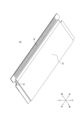
- FIG. 4 is an external perspective view showing a connection object in a state not held by the first connector as viewed from above;
- FIG. 4 is an external perspective view showing a connecting object in a state not held by the first connector as viewed from below;
- 3 is an enlarged view enlarging a portion V surrounded by a dashed line in FIG. 2.
- FIG. It is the external appearance perspective view which showed the 1st metal member single-piece
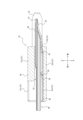
- FIG. 3 is a cross-sectional view along the VII-VII arrow line in FIG. 2;
- FIG. 3 is a cross-sectional view along the VIII-VIII arrow line in FIG. 2;
- FIG. 3 is a cross-sectional view along the IX-IX arrow line in FIG. 2;
- FIG. 2 is an external perspective view showing the second connector alone in FIG. 1 as viewed from the rear and top;
- FIG. 2 is an external perspective view showing the second connector alone in FIG. 1 as viewed from the front and above;
- FIG. 12 is an exploded perspective view of the second connector unit of FIG. 11;
- FIG. 2 is a cross-sectional view taken along line XIII-XIII in FIG. 1;
- 2 is a cross-sectional view taken along line XIV-XIV in FIG.
- FIG. FIG. 2 is a cross-sectional view taken along the line XV-XV of FIG. 1; It is the external appearance perspective view which showed the 1st metal member simple substance which concerns on a modification by the top view.
- 15 is a cross-sectional view corresponding to FIG. 14, showing a cross-section of a connector module according to a modification; FIG.
- the first connector and connector module according to one embodiment of the present disclosure, it is possible to obtain good transmission characteristics in signal transmission.
- FIG. 1 is an external perspective view of a connector module 1 according to an embodiment in which a first connector 10 holding a connection object 40 and a second connector 50 are connected to each other.
- FIG. 2 is an external perspective view showing the first connector 10 of FIG. 1 holding the connection object 40 as viewed from below. Configurations of a connector module 1 and a first connector 10 according to an embodiment will be mainly described with reference to FIGS. 1 and 2.
- FIG. 1 is an external perspective view of a connector module 1 according to an embodiment in which a first connector 10 holding a connection object 40 and a second connector 50 are connected to
- the connector module 1 has a first connector 10 and a second connector 50 connectable to each other.
- the second connector 50 is mounted on the circuit board CB.
- the circuit board CB may be a rigid board or any other circuit board.
- the second connector 50 electrically connects the connection object 40 inserted into the second connector 50 together with the first connector 10 and the circuit board CB.
- the second connector 50 can insert and remove the connection object 40 via the first connector 10 , and is connected to the connection object 40 in a state where the connection object 40 is inserted.
- the second connector 50 has a second insulator 60, a first contact 70a, a second contact 70b, and a second metal member 80.
- the first contact 70 a , the second contact 70 b and the second metal member 80 are attached to the second insulator 60 .
- the first connector 10 holds a connection object 40.
- the first connector 10 receives the connection object 40 inserted from the front to the rear, and supports both ends of the connection object 40 in the left-right direction, thereby holding the connection object 40 as a whole.
- connection object 40 held by the first connector 10 is, for example, an FFC.
- the connection object 40 is not limited to this, and may be any cable as long as it is electrically connected to the circuit board CB via the first connector 10 and the second connector 50 .
- the connection object 40 may be an FPC.
- the connection object 40 is not limited to cables as described above, and may include any object.
- connection object 40 may include a rigid substrate or any other circuit substrate.
- the first connector 10 can be connected to the second connector 50 while holding the connection target 40 .
- the first connector 10 has a first insulator 20 fitted with the second insulator 60 in a connected state in which the first connector 10 and the second connector 50 are connected to each other.
- the first connector 10 has a first metal member 30 attached to the first insulator 20 .
- connection object 40 contacts the second contact 70b in a fitted state in which the first insulator 20 and the second insulator 60 are fitted to each other.
- the first metal member 30 contacts the first contact 70a in a fitted state in which the first insulator 20 and the second insulator 60 are fitted to each other.
- the second connector 50 is a receptacle connector.
- the first connector 10 is described as a plug connector.
- the second connector 50 in which the first contacts 70a and the second contacts 70b are elastically deformed when the first insulator 20 and the second insulator 60 are fitted to each other will be described as a receptacle connector.
- the first connector 10 holding the connection object 40 in the fitted state will be described as a plug connector.
- the types of the first connector 10 and the second connector 50 are not limited to these.
- the second connector 50 may act as a plug connector and the first connector 10 as a receptacle connector.
- connection object 40 is inserted into the second connector 50 in a direction parallel to the circuit board CB on which the second connector 50 is mounted.
- the connection object 40 is inserted into the second connector 50 along the front-rear direction, for example.
- the object to be connected 40 may be inserted into the second connector 50 in a direction perpendicular to the circuit board CB on which the second connector 50 is mounted.
- the connection object 40 may be inserted into the second connector 50 along the vertical direction.
- the "extending direction of the contact line” used below means the front-back direction as an example.
- the “insertion/removal direction” means, for example, the front-rear direction.
- a direction orthogonal to the extending direction of the contact line” means, for example, a vertical direction.
- the “tip of the connection object” means, for example, the rear tip of the connection object.
- “Withdrawal side” means the front side as an example.
- “Insertion side” means the rear side, by way of example.
- FIG. 3 is an external perspective view showing the connection object 40 not held by the first connector 10 as viewed from above.
- FIG. 4 is an external perspective view showing the connection object 40 not held by the first connector 10 as viewed from below.
- the configuration of the connection object 40 held by the first connector 10 will be mainly described with reference to FIGS. 3 and 4.
- the object to be connected 40 has a laminated structure formed by bonding a plurality of thin film materials to each other.
- the object to be connected 40 has a reinforcing portion 41 that constitutes a leading end portion in the direction in which the object to be connected 40 extends, that is, the direction in which the object to be connected 40 is inserted and withdrawn, and that is harder than the other portions.
- the object to be connected 40 has a plurality of contact lines 42 that extend linearly along the inserting/removing direction and extend to the tip of the reinforcing portion 41 .
- the contact wire 42 is exposed downward at the tip of the connection object 40 .
- the connection object 40 has a first ground part 43 that covers part of the contact wire 42 on the removal side of the connection object 40 with the lower outermost layer.
- the first ground portion 43 extends in a flat plate shape from the front to the rear and is bent obliquely upward at its tip.
- the connection object 40 has a second ground portion 44 covering substantially the entire contact wire 42 with the uppermost outer layer.
- the second ground portion 44 extends in a flat plate shape from the front to the rear, and is laminated above the reinforcement portion 41 at the tip portion of the second ground portion 44 while bending obliquely upward at the front edge portion of the reinforcement portion 41 . ing.
- the object to be connected 40 has a locked portion 45 in which the central portion is notched inward in the left-right direction at the end edge along the front-rear direction of the tip of the object to be connected 40 including the reinforcing portion 41 .
- the locked portions 45 are formed on both sides in the left-right direction at the distal end portion of the connection object 40 including the reinforcing portion 41 .
- FIG. 5 is an enlarged view of the portion V enclosed by the dashed-dotted line in FIG.
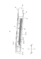
- FIG. 6 is an external perspective view showing the first metal member 30 alone as viewed from above.
- FIG. 7 is a cross-sectional view taken along line VII--VII in FIG.
- FIG. 8 is a cross-sectional view taken along line VIII-VIII in FIG.
- FIG. 9 is a cross-sectional view taken along line IX-IX in FIG.
- the configuration of the first connector 10 according to one embodiment will be mainly described with reference to FIGS. 2 and 5 to 9.
- FIG. 1 is an enlarged view of the portion V enclosed by the dashed-dotted line in FIG.
- FIG. 6 is an external perspective view showing the first metal member 30 alone as viewed from above.
- FIG. 7 is a cross-sectional view taken along line VII--VII in FIG.
- FIG. 8 is a cross-sectional view taken along line VIII-VIII in FIG.
- FIG. 9 is a cross-section
- the first insulator 20 is a symmetrical box-shaped member injection-molded from an insulating and heat-resistant synthetic resin material.
- the first insulator 20 has four outer walls in the vertical and horizontal directions, and has an outer peripheral wall 21 formed in a rectangular shape as a whole.
- the outer peripheral wall 21 has a ceiling wall 21a, a bottom wall 21b, and a pair of side walls 21c.
- the first insulator 20 has a protruding portion 22 that protrudes from the side wall 21c toward the insertion side of the connection object 40 from the ceiling wall 21a and the bottom wall 21b.
- the first insulator 20 has an insertion portion 23 surrounded by an outer peripheral wall 21 in the vertical and horizontal directions. As shown in FIG. 7 , the first insulator 20 has a holding portion 24 recessed inside the projecting portion 22 . The first insulator 20 has a lock portion 25 that extends from the center portion of the side wall 21c in the front-rear direction to the center portion of the holding portion 24 in the front-rear direction. The locking portion 25 is elastically deformable in the vertical direction. As shown in FIGS. 8 and 9, the first insulator 20 has a mounting portion 26 formed along the upper surface of the bottom wall 21b.
- the first metal member 30 is formed by molding a thin plate of any metal material into the shape shown in FIG. 6 using a progressive die (stamping).
- the first metal member 30 is formed by bending in the plate thickness direction after punching.
- the processing method of the first metal member 30 is not limited to this, and may include only the step of punching, for example.
- the surface of the first metal member 30 is surface-plated with gold, tin, or the like after a base is formed by nickel plating. Plating, including nickel plating and surface layer plating, may be partially applied to required locations.
- the first metal member 30 has a first base portion 31 formed in a plate shape in the front, rear, left, and right directions.
- the first base portion 31 includes a first portion 31a that is formed as a flat plate extending in the front, rear, left, and right directions, and a second portion 31b that is bent obliquely upward from the rear edge of the first portion 31a and extends horizontally again. include.
- the first metal member 30 has a first contact portion 32 extending rearward from the rear edge portion of the first base portion 31, for example, the second portion 31b.
- the first contact portion 32 bends obliquely upward from the rear edge portion of the second portion 31 b and extends horizontally again at the rear end portion of the first contact portion 32 .
- the first contact portion 32 is formed to be wide in the left-right direction from the portion connected to the second portion 31b to the central portion of the portion extending obliquely upward. It is formed to be tapered.
- the first contact portion 32 is notched in the plate thickness direction at the central portion of the portion formed to be wide in the left-right direction.
- the first contact portion 32 is elastically deformable in the vertical direction.
- the first metal member 30 has a second contact portion 33 that is positioned forward of the first contact portion 32 and extends rearward from the rear portion of the first base portion 31, for example, the first portion 31a.
- the second contact portion 33 linearly extends obliquely upward from the rear portion of the first portion 31a and bends upward at the rear end portion of the second contact portion 33.
- the second contact portion 33 is tapered such that the width in the left-right direction continuously decreases from the portion connected to the first portion 31a to the rear end portion.
- the entirety of the second contact portion 33 is accommodated in the portions of the second portion 31b and the first contact portion 32 that are notched in the plate thickness direction.
- a rear end portion of the second contact portion 33 is arranged in a portion of the first contact portion 32 that is cut out in the plate thickness direction.
- the second contact portion 33 is elastically deformable in the vertical direction.
- the first contact portion 32 and the second contact portion 33 are formed in four pairs in total, two pairs on the left side and two pairs on the right side of the first metal member 30 .
- Each set of the first contact portion 32 and the second contact portion 33 is arranged in a state separated from each other along the left-right direction.
- the first contact portion 32 and the second contact portion 33 are linearly arranged along the front-rear direction.
- the first metal member 30 has a plurality of jumping parts 34 arranged at regular intervals along the left-right direction in the front-back direction central part of the first part 31 a of the first base part 31 .
- the jumping portion 34 extends obliquely upward in a straight line from the first portion 31 a and bends upward at the rear end portion of the jumping portion 34 .
- the jumping portion 34 is formed in a tapered shape so that the width in the left-right direction continuously decreases from the portion connected to the first portion 31a to the rear end portion.
- the entire jumping portion 34 is located above the portion of the first portion 31a that is notched in the plate thickness direction.
- the jumping portion 34 is elastically deformable along the vertical direction.
- the jumping portion 34 is not arranged on the same straight line as the set of the first contact portion 32 and the second contact portion 33, but is formed at a laterally offset position.
- the first metal member 30 has locking portions 35 formed on both lateral edge portions of the first portion 31 a of the first base portion 31 .
- the first connector 10 is configured such that the first metal member 30 is inserted from the front side of the first insulator 20 into the first insulator 20 from the front to the rear. be assembled with The first metal member 30 is held by the first insulator 20 while being attached to the attachment portion 26 of the first insulator 20 .
- the function of the first connector 10 when the first metal member 30 is attached to the first insulator 20 will be mainly described below.
- the locking portion 35 is locked to the lateral inner surface of the side wall 21c.
- the rear corners of the left and right edges of the first portion 31a of the first base portion 31 face the forward inner surface of the side wall 21c.
- the first metal member 30 is arranged along the bottom wall 21b of the first connector 10 and substantially all over the lower portion of the first connector 10. As shown in FIG. The first portion 31a of the first base portion 31 contacts the upper surface of the bottom wall 21b. The first contact portion 32 and the second contact portion 33 extend obliquely upward rearward from the rear end of the bottom wall 21b. A rear end portion of the jump portion 34 is positioned inside the insertion portion 23 .
- connection object 40 With the first metal member 30 attached to the first insulator 20 , the connection object 40 is inserted into the insertion portion 23 of the first insulator 20 from the front side of the insertion portion 23 from the front to the rear.
- the function of the first connector 10 when the connection object 40 is inserted into the first insulator 20 and the first connector 10 is attached to the connection object 40 will be mainly described.
- the holding portion 24 accommodates the tip of the connection object 40 and holds the connection object. hold an object 40;
- the locking portion 25 engages with the locked portion 45 .
- the locking portion 25 functions as a stopper for the connection target 40 from the first connector 10 and suppresses unintended removal of the connection target 40 from the first connector 10 .
- the first connector 10 stably holds the connection object 40 .
- the first contact portion 32 extends from the first base portion 31 toward the tip of the connection object 40 and contacts the contact wire 42 .
- the second contact portion 33 is located on the opposite side of the tip of the connection target 40 from the first contact portion 32 and contacts the first ground portion 43 .
- the first contact portion 32 and the second contact portion 33 contact the connection object 40 while being elastically deformed downward.
- the first contact portion 32 and the second contact portion 33 are positioned on the same side with respect to the connection object 40 in the direction orthogonal to the extending direction of the contact line 42 . More specifically, the first contact portion 32 and the second contact portion 33 are orthogonal to both the extending direction of the contact line 42 and the arrangement direction of the first contacts 70a and the second contacts 70b of the second connector 50. They are positioned on the same side with respect to the connection object 40 in the vertical direction.
- the first contact portion 32 contacts a portion of the contact wire 42 adjacent to the boundary R between the contact wire 42 and the first ground portion 43 .
- the second contact portion 33 contacts a portion adjacent to the boundary R in the first ground portion 43 .
- the first contact portion 32 and the second contact portion 33 are arranged linearly along the extending direction of the contact line 42 .
- one first contact portion 32 contacts a plurality of contact lines 42 .
- one first contact portion 32 contacts two contact lines 42 adjacent to each other along the left-right direction.
- the spring portion 34 extends rearward from the first base portion 31 and contacts the first ground portion 43 .
- the jumping portion 34 is located on the opposite side of the tip of the connection object 40 from the first contact portion 32 and the second contact portion 33 .
- the jumping portion 34 contacts the connection object 40 while being elastically deformed downward.
- the jumping portion 34 is located on the same side of the connecting object 40 as the first contact portion 32 and the second contact portion 33 in the direction orthogonal to the extending direction of the contact line 42 .
- the jump part 34 is not arranged linearly along the extending direction of the contact line 42 with respect to the first contact part 32 and the second contact part 33, but is formed at a position shifted in the left-right direction. ing.
- the second portion 31 b of the first base portion 31 extends rearward from the first portion 31 a and contacts the first ground portion 43 .
- the second portion 31 b is located on the opposite side of the tip of the connection target 40 from the first contact portion 32 and the second contact portion 33 .
- the second portion 31 b is located on the same side of the connection object 40 as the first contact portion 32 and the second contact portion 33 in the direction orthogonal to the extending direction of the contact line 42 .
- FIG. 10 is an external perspective view showing the second connector 50 alone in FIG. 1 as viewed from the rear and top.
- FIG. 11 is an external perspective view showing the second connector 50 alone in FIG. 1 as viewed from the front and above.
- 12 is an exploded perspective view of the second connector 50 alone in FIG. 11.
- the second connector 50 is assembled by the following method as an example.
- the first contact 70 a and the second contact 70 b are press-fitted into the second insulator 60 from behind the second insulator 60 .
- the second metal member 80 is press-fitted into the second insulator 60 so as to cover the entirety of the second insulator 60 from above.
- the second connector 50 is mounted on the circuit board CB.
- the second connector 50 electrically connects the connection object 40 and the circuit board CB via the first contacts 70a and the second contacts 70b.
- the second insulator 60 is a symmetrical box-shaped member injection-molded from an insulating and heat-resistant synthetic resin material.
- the second insulator 60 is not limited to this, and may be formed asymmetrically in the left-right direction.
- the second insulator 60 has four outer walls in the vertical and horizontal directions, and has an outer peripheral wall 61 formed in a rectangular shape as a whole.
- the outer peripheral wall 61 has a ceiling wall 61a, a bottom wall 61b, and a pair of side walls 61c.
- the second insulator 60 has a rear wall 62 formed continuously with a ceiling wall 61a and a pair of side walls 61c. As shown in FIGS. 11 and 12 , the second insulator 60 has an insertion portion 63 surrounded by an outer peripheral wall 61 in the vertical and horizontal directions. The front side of the insertion portion 63 is largely opened by the opening of the second insulator 60 . On the other hand, the rear side of the insertion portion 63 is closed by the rear wall 62 .
- the second insulator 60 has a first hole portion 64a penetrating through the ceiling wall 61a from the upper surface of the ceiling wall 61a to the insertion portion 63.
- the first hole portion 64a extends linearly over substantially the entire ceiling wall 61a along the front-rear direction.
- a total of four first holes 64a are formed in the ceiling wall 61a, two on the left side and two on the right side.
- the first holes 64a are arranged so as to be spaced apart from each other along the left-right direction.
- the second insulator 60 has second holes 64b formed at both ends of the ceiling wall 61a in the left-right direction and penetrating the ceiling wall 61a from the upper surface of the ceiling wall 61a to the insertion portion 63.
- a pair of the second hole portions 64b are arranged on both outer sides in the left-right direction with respect to the entire four first hole portions 64a.
- the second hole portion 64b extends linearly over substantially the entire ceiling wall 61a along the front-rear direction.
- the second insulator 60 has a plurality of third holes 64c arranged in the front edge of the ceiling wall 61a while being spaced apart from each other in the left-right direction. As shown in FIG. 10, the second insulator 60 has a plurality of fourth holes 64d arranged in the upper edge of the rear wall 62 while being spaced apart from each other in the left-right direction.
- the second insulator 60 includes a plurality of contact mounting grooves 65 extending in the front-rear direction from the outer surface of the rear wall 62 to the interior of the insertion portion 63 .
- the plurality of contact mounting grooves 65 are arranged in the left-right direction at predetermined intervals.
- the contact mounting groove 65 includes a first contact mounting groove 65a and a second contact mounting groove 65b.
- the first contact mounting grooves 65a are recessed at positions matching the number and mounting positions of the first contacts 70a shown in FIG.
- the second contact mounting grooves 65b are recessed at positions matching the number and mounting positions of the second contacts 70b shown in FIG.
- the first contact 70a is made of, for example, a spring-elastic copper alloy containing phosphor bronze, beryllium copper, or titanium copper, or a thin plate of a Corson copper alloy, which is formed into the shape shown in FIG. 12 using a progressive die (stamping). It is processed.
- the first contact 70a is formed only by punching.
- the processing method of the first contact 70a is not limited to this, and may include, for example, a step of bending in the plate thickness direction after punching.
- the surface of the first contact 70a is surface-layer plated with gold, tin, or the like after a base is formed by nickel plating.
- a total of eight first contacts 70a are arranged in the second connector 50, four on the left side and four on the right side.
- the first contact 70a is formed in a rectangular shape and has a locking portion 71a having a projection on its upper edge.
- the first contact 70a has a mounting portion 72a extending rearward in an L shape from the lower end portion of the locking portion 71a.
- the first contact 70a has a third contact portion 73a that extends forward while being bent from the front end portion of the locking portion 71a.
- the first contact 70a has a sixth contact portion 74a positioned at the rear edge of the locking portion 71a.
- the second contact 70b is made of, for example, a spring-elastic copper alloy containing phosphor bronze, beryllium copper, or titanium copper, or a thin plate of a Corson copper alloy, which is formed into the shape shown in FIG. 12 using a progressive die (stamping). It is processed.
- the second contact 70b is formed only by punching.
- the processing method of the second contact 70b is not limited to this, and may include, for example, a step of bending in the plate thickness direction after punching.
- the surfaces of the second contacts 70b are surface-layer plated with gold, tin, or the like after a base is formed by nickel plating.
- a plurality of second contacts 70b are arranged in the second connector 50 so as to be separated from each other in the left-right direction.
- the second contact 70b is formed in a rectangular shape and has a locking portion 71b having a projection on its upper edge.
- the second contact 70b has a mounting portion 72b extending rearward in an L shape from the lower end portion of the locking portion 71b.
- the second contact 70b has a fourth contact portion 73b that bends and extends forward from the front end portion of the locking portion 71b.
- the second metal member 80 is formed by forming a thin plate of any metal material into the shape shown in FIG. 12 using a progressive die (stamping).
- the second metal member 80 is formed by bending in the plate thickness direction after punching.
- the processing method of the second metal member 80 is not limited to this, and may include, for example, only the step of punching.
- the second metal member 80 has a second base portion 81 that constitutes its upper portion and is formed in a plate shape. As shown in FIG. 10, the second metal member 80 has a third base portion 82 that extends downward while bending from a second base portion 81 . The second metal member 80 has a fifth contact portion 83 linearly extending downward from the third base portion 82 .
- the second metal member 80 has a plurality of first claws 84a extending like a crank from the front edge of the second base 81. As shown in FIG. The plurality of first claw portions 84a are arranged while being spaced apart from each other in the left-right direction. The first claw portion 84 a engages with the third hole portion 64 c of the second insulator 60 while the second metal member 80 is attached to the second insulator 60 .
- the second metal member 80 has a plurality of second claws 84b protruding forward from the lower edge of the third base 82 so as to be folded back.
- the plurality of second claw portions 84b are arranged while being spaced apart from each other in the left-right direction.
- the second claw portion 84b engages with the fourth hole portion 64d of the second insulator 60 shown in FIG. 10 in a state where the second metal member 80 is attached to the second insulator 60.
- the second metal member 80 has a first locking portion 85a that extends downward in a U shape from both lateral end portions of the rear edge portion of the second base portion 81 . With the second metal member 80 attached to the second insulator 60, the first locking portion 85a is locked to the rear wall 62 of the second insulator 60 shown in FIG.
- the second metal member 80 has a second locking portion 85b that extends downward while being bent from the left-right edge portion of the second base portion 81 .
- the second locking portion 85b is locked to the side wall 61c of the second insulator 60 shown in FIG. 11 in a state where the second metal member 80 is attached to the second insulator 60.
- the second metal member 80 has a mounting portion 86 that extends outward in the left-right direction while being bent from the front end of the lower edge portion of the second locking portion 85b.
- the second metal member 80 has a seventh contact portion 87 extending forward from the second base portion 81 .
- the seventh contact portion 87 is bent in a U shape and then extends obliquely downward toward the front.
- Four seventh contact portions 87 are formed in the second metal member 80 .
- the plurality of seventh contact portions 87 are arranged while being spaced apart from each other in the left-right direction.
- the seventh contact portion 87 is elastically deformable along the vertical direction.
- the second metal member 80 has engaging portions 88 that linearly extend obliquely downward from both left and right end portions of the second base portion 81 .
- the engaging portion 88 is elastically deformable in the vertical direction.
- the second connector 50 is mounted on the circuit forming surface formed on the upper surface of the circuit board CB. More specifically, the mounting portion 72a of the first contact 70a is mounted on the solder paste applied to the pattern on the circuit board CB. The mounting portion 72b of the second contact 70b is mounted on the solder paste applied to the pattern on the circuit board CB. The mounting portion 86 of the second metal member 80 is placed on the solder paste applied to the pattern on the circuit board CB. By heating and melting each solder paste in a reflow oven or the like, the mounting portion 72a, the mounting portion 72b, and the mounting portion 86 are soldered to the pattern. As a result, the mounting of the second connector 50 on the circuit board CB is completed. Electronic components other than the second connector 50, such as a CPU (Central Processing Unit), a controller, or a memory, are mounted on the circuit forming surface of the circuit board CB.
- a CPU Central Processing Unit
- controller or a memory
- FIG. 13 is a cross-sectional view taken along line XIII-XIII in FIG.
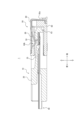
- FIG. 14 is a cross-sectional view taken along line XIV-XIV in FIG.
- FIG. 15 is a cross-sectional view taken along line XV-XV in FIG.
- the projecting portion 22 of the first insulator 20 is received in the insertion portion 63 of the second insulator 60.
- the engaging portion 88 of the second metal member 80 extends into the insertion portion 63 through the second hole portion 64b of the second insulator 60 .
- the first contact 70 a is attached to the second insulator 60 by engaging with the first contact attachment groove 65 a of the second insulator 60 .
- a third contact portion 73 a of the first contact 70 a contacts the first metal member 30 . More specifically, the third contact portion 73 a contacts the first contact portion 32 of the first metal member 30 . At this time, the third contact portion 73a elastically deforms downward.
- the third contact portion 73 a is located on the same side as the first contact portion 32 with respect to the connection object 40 in the direction orthogonal to the extending direction of the contact line 42 .
- a fifth contact portion 83 of the second metal member 80 extends from a portion of the second metal member 80 including the second base portion 81 and contacts the first contact 70a. As also shown in FIG. 10, the fifth contact portion 83 contacts two first contacts 70a adjacent to each other in the left-right direction.
- a third base portion 82 of the second metal member 80 extends from the second base portion 81 while bending toward the first contact 70 a and along the end surface of the second insulator 60 in the extending direction of the contact line 42 .
- the sixth contact portion 74 a of the first contact 70 a contacts the fifth contact portion 83 of the second metal member 80 .
- the third contact portion 73a and the sixth contact portion 74a are located at both ends of the first contact 70a in the extending direction of the contact wire 42, respectively.
- the first contact 70 a contacts both the first metal member 30 of the first connector 10 and the second metal member 80 of the second connector 50 .
- the first contact 70a is used for ground as an example.
- the second contact 70b is attached to the second insulator 60 by engaging with the second contact attachment groove 65b of the second insulator 60.
- a fourth contact portion 73 b of the second contact 70 b contacts the contact line 42 .
- the fourth contact portion 73b is elastically deformed downward.
- the fourth contact portion 73b is located on the same side as the first contact portion 32 with respect to the connection object 40 in the direction orthogonal to the extending direction of the contact line 42 .
- the second contact 70b is in direct contact with the contact wire 42 of the connection object 40.
- the second contact 70b is used for signals as an example.
- the seventh contact portion 87 of the second metal member 80 is arranged in the first hole portion 64 a of the second insulator 60 .
- the seventh contact portion 87 of the second metal member 80 extends obliquely downward from the second base portion 81 while being bent in a U shape to contact the connection object 40 . More specifically, the seventh contact portion 87 contacts the second ground portion 44 of the connection object 40 . At this time, the seventh contact portion 87 is elastically deformed upward.
- the first connector 10 it is possible to obtain good transmission characteristics in signal transmission.
- the first contact portion 32 of the first metal member 30 contacts the contact line 42 of the connection object 40 and the second contact portion 33 contacts the first ground portion 43 .
- the contact line 42, the first metal member 30, and the first ground portion 43 function stably as one ground.
- a part of the plurality of contact lines 42 stably functions as a ground, thereby suppressing crosstalk between the other plurality of contact lines 42 through which electrical signals are transmitted.
- the first contact portion 32 and the second contact portion 33 are positioned on the same side with respect to the connection object 40 in the direction orthogonal to the extending direction of the contact line 42, so that the first metal member 30 and the connection object It becomes possible to arrange all the contact structures with the object 40 on the same side. For example, by arranging such contact structures only on the lower side of the connection object 40 and not on the upper side, the height of the first connector 10 can be reduced compared to the case where the contact structures are arranged on both sides. It becomes possible. As a result, the height of the entire connector module 1 can be reduced. In addition, the first contact portion 32 and the second contact portion 33 contact the connection object 40 on the same side with respect to the connection object 40 . As a result, crosstalk between the plurality of contact lines 42 through which electrical signals are transmitted is suppressed compared to the case where the contact structures are arranged on both upper and lower sides and are brought into contact with the connection object 40 .
- the first contact portion 32 contacts the portion of the contact line 42 adjacent to the boundary R, and the second contact portion 33 contacts the portion of the first ground portion 43 adjacent to the boundary R, whereby the first contact portion 32 and The distance to the second contact portion 33 can be shortened.
- the contact portion between the first metal member 30 and the contact line 42 and the contact portion between the first metal member 30 and the first ground portion 43 are close to each other. Therefore, the contact line 42, the first metal member 30, and the first ground portion 43 function more stably as one ground. As a result, crosstalk between other contact lines 42 through which electrical signals are transmitted is further suppressed, and transmission characteristics in signal transmission are further improved.
- the first contact portion 32 and the second contact portion 33 By arranging the first contact portion 32 and the second contact portion 33 in a straight line along the extending direction of the contact line 42, compared to the case where the first contact portion 32 and the second contact portion 33 are arranged in a state of being shifted from each other on the same straight line. can shorten the distance between them.
- the contact portion between the first metal member 30 and the contact line 42 and the contact portion between the first metal member 30 and the first ground portion 43 are close to each other. Therefore, the contact line 42, the first metal member 30, and the first ground portion 43 function more stably as one ground. As a result, crosstalk between other contact lines 42 through which electrical signals are transmitted is further suppressed, and transmission characteristics in signal transmission are further improved.
- the first contact portion 32 and the second contact portion 33 are elastically deformable, and by contacting the connection object 40 in an elastically deformed state, contact reliability is improved. For example, even if the connection object 40 vibrates, the first contact portion 32 and the second contact portion 33 are elastically deformed, so that the contact with the connection object 40 is more reliably maintained.
- the connection object 40 when the connection object 40 is inserted into the first connector 10 , it is possible to absorb the vertical thickness tolerance of the connection object 40 . Therefore, workability when inserting and holding the connection object 40 in the first connector 10 is improved.
- the first connector 10 can improve contact reliability with the connection object 40 compared to the case where the first contact portion 32 and the second contact portion 33 are not elastically deformed. As described above, the assembling efficiency between the first connector 10 and the connection object 40 is improved. As a result, productivity is improved when electronic equipment is produced by electrically connecting the connection object 40 and the circuit board CB via the connector module 1 .
- the contact between the first metal member 30 and the contact wires 42 of the object to be connected 40 is made more reliable by having one first contact portion 32 in contact with the plurality of contact wires 42 . Robustness is improved when the first metal member 30 and the contact line 42 contact each other. As a result, the contact line 42, the first metal member 30, and the first ground portion 43 function more stably as one ground. This further suppresses crosstalk between other contact lines 42 through which electrical signals are transmitted.
- the contact line 42, the first metal member 30, and the first ground portion 43 function as one shield.
- the first contact 70a of the second connector 50 Since the first contact 70a of the second connector 50 has the third contact portion 73a that contacts the first metal member 30, the number of ground contact points is increased.
- the first contact 70 a of the second connector 50 can also be electrically connected to the first ground portion 43 via the first metal member 30 . Therefore, the first contact 70a, the contact line 42, the first metal member 30, and the first ground portion 43 function stably as one ground. As a result, crosstalk between other contact lines 42 through which electrical signals are transmitted is further suppressed, and transmission characteristics in signal transmission are further improved.
- the first contact 70 a indirectly contacts the plurality of contact lines 42 via the third contact portion 73 a and the first metal member 30 . This also makes it possible to easily change the horizontal spacing of the first contacts 70a.
- the third contact portion 73a is located on the same side as the first contact portion 32 with respect to the connection object 40 in the direction orthogonal to the extending direction of the contact wire 42.
- the contact structure between the first contact 70a and the first metal member 30 and the contact structure between the first metal member 30 and the connection object 40 can all be arranged on the same side. For example, by arranging these contact structures only on the lower side of the connection object 40 and not on the upper side, the height of the entire connector module 1 can be reduced compared to the case where the contact structures are arranged on both sides. becomes.
- the second contact 70b has a fourth contact portion 73b that contacts the contact wire 42, and the fourth contact portion 73b contacts the first contact portion 32 with respect to the connection object 40 in a direction orthogonal to the extending direction of the contact wire 42. located on the same side as As a result, the contact structure between the second contact 70b and the connection object 40 and the contact structure between the first metal member 30 and the connection object 40 can all be arranged on the same side. For example, by arranging these contact structures only on the lower side of the connection object 40 and not on the upper side, the height of the entire connector module 1 can be reduced compared to the case where the contact structures are arranged on both sides. becomes.
- the fifth contact portion 83 of the second metal member 80 extends from a portion of the second metal member 80 including the second base portion 81 and comes into contact with the first contact 70a, thereby increasing the contact points as ground.
- the second metal member 80 can also be electrically connected to the first ground portion 43 via the first contact 70 a and the first metal member 30 . Therefore, the second metal member 80, the first contact 70a, the contact line 42, the first metal member 30, and the first ground portion 43 function stably as one ground. As a result, crosstalk between other contact lines 42 through which electrical signals are transmitted is further suppressed, and transmission characteristics in signal transmission are further improved.
- the second metal member 80 is press-fitted into the second insulator 60 so as to cover the entire second insulator 60 from above, thereby suppressing the outflow and inflow of noise for electrical signals.
- electromagnetic noise generated from the electrical signal transmitted by the second contact 70b is suppressed from flowing out of the second connector 50 .
- electromagnetic noise generated from other electronic components arranged on the circuit board CB is suppressed from flowing into the second connector 50 .
- a fifth contact portion 83 extends from the third base portion 82 along the end surface of the second insulator 60 in the extending direction of the contact wire 42 while bending from the second base portion 81 toward the first contact 70a.
- the robustness as the strength of the contact portion is improved. Therefore, the second metal member 80 and the first contact 70 a can stably contact each other through the fifth contact portion 83 .
- the second metal member 80, the first contact 70a, the contact line 42, the first metal member 30, and the first ground portion 43 function more stably as one ground. This further suppresses crosstalk between a plurality of other contact lines 42 through which electrical signals are transmitted, further improving transmission characteristics in signal transmission.
- the third contact portion 73a and the sixth contact portion 74a are located at both ends of the first contact 70a in the extending direction of the contact wire 42, respectively.
- This enables stable contact of the first contacts 70 a with both the first metal member 30 of the first connector 10 and the second metal member 80 of the second connector 50 . Therefore, the first metal member 30 and the second metal member 80 can be stably electrically connected to each other through the first contact 70a.
- the second metal member 80, the first contact 70a, the contact line 42, the first metal member 30, and the first ground portion 43 function more stably as one ground. This further suppresses crosstalk between a plurality of other contact lines 42 through which electrical signals are transmitted, further improving transmission characteristics in signal transmission.
- the seventh contact portion 87 of the second metal member 80 extends from the second base portion 81 and comes into contact with the connection object 40, thereby increasing the contact points as the ground.
- the second metal member 80 is electrically connected to the first ground portion 43 of the connection object 40 through the fifth contact portion 83 and the second ground portion of the connection object 40 through the seventh contact portion 87 . 44 are also electrically connected. Therefore, the second ground portion 44 can also be electrically connected to the first ground portion 43 via the second metal member 80 , the first contact 70 a and the first metal member 30 .
- the second ground portion 44, the second metal member 80, the first contact 70a, the contact line 42, the first metal member 30, and the first ground portion 43 function stably as one ground.
- crosstalk between other contact lines 42 through which electrical signals are transmitted is further suppressed, and transmission characteristics in signal transmission are further improved.
- the contact reliability is improved because the seventh contact portion 87 is elastically deformable. For example, even if the connection object 40 vibrates, the seventh contact portion 87 is elastically deformed, so that the contact with the connection object 40 is more reliably maintained.
- the vertical thickness tolerance of the connection object 40 can be absorbed. Therefore, workability when inserting the connection object 40 held by the first connector 10 into the second connector 50 is improved.
- the second connector 50 can hold the connection object 40 more stably than when the seventh contact portion 87 is not elastically deformed.
- the second connector 50 can also improve contact reliability with the connection target 40 . As described above, the ease of assembly between the second connector 50 and the object to be connected 40 is improved. As a result, productivity is improved when electronic equipment is produced by electrically connecting the connection object 40 and the circuit board CB via the connector module 1 .
- each component described above are not limited to the contents shown in the above description and drawings.
- the shape, arrangement, orientation, number, and the like of each component may be arbitrarily configured as long as the function can be realized.
- the method of assembling the first connector 10 described above is not limited to the contents of the above description.
- the first connector 10 may be assembled by any method as long as it can be assembled so that each function can be exhibited.
- the first metal member 30 may be integrally formed with the first insulator 20 by insert molding instead of press fitting.
- the method of assembling the second connector 50 described above is not limited to the contents of the above description. Any method may be used for assembling the second connector 50 as long as it can be assembled so that each function can be exhibited.
- at least one of the first contact 70a, the second contact 70b, and the second metal member 80 may be integrally formed with the second insulator 60 by insert molding instead of press fitting.
- first contact portion 32 and the second contact portion 33 are positioned on the same side with respect to the object to be connected 40 in the direction perpendicular to the extending direction of the contact line 42. Not limited. The first contact portion 32 and the second contact portion 33 may be positioned on different sides of the connection object 40 .
- the first contact portion 32 contacts the portion of the contact line 42 adjacent to the boundary R
- the second contact portion 33 contacts the portion of the first ground portion 43 adjacent to the boundary R. It is not limited to this.
- the first contact portion 32 and the second contact portion 33 may contact arbitrary portions of the contact line 42 and the first ground portion 43, respectively.
- first contact portion 32 and the second contact portion 33 are arranged linearly along the extending direction of the contact line 42, but the present invention is not limited to this.
- the first contact portion 32 and the second contact portion 33 may be arranged not on the same straight line but on different straight lines along the extending direction of the contact line 42 .
- both the first contact portion 32 and the second contact portion 33 are elastically deformable, and are in contact with the connection object 40 in an elastically deformed state, but the present invention is not limited to this. Either one of the first contact portion 32 and the second contact portion 33 may be elastically deformable, or neither of them may be elastically deformable.
- one first contact portion 32 contacts two contact lines 42 adjacent to each other, but the present invention is not limited to this.
- One first contact portion 32 may contact three or more contact lines 42 or may contact only one contact line 42 .
- the first contact portion 32 and the second contact portion 33 are formed in two pairs on the left side and two pairs on the right side of the first metal member 30, for a total of four pairs. but not limited to this.
- Each of the first contact portions 32 and the second contact portions 33 may be formed in an arbitrary number at arbitrary positions different from the positions shown in FIG.
- the present invention is not limited to this.
- the first contact 70 a may contact, for example, the contact wire 42 of the connection object 40 without contacting the first metal member 30 .
- the first contact 70a may be used for signals instead of for ground.
- the third contact portion 73a is positioned on the same side as the first contact portion 32 with respect to the connection object 40 in the direction orthogonal to the extending direction of the contact line 42, but the present invention is not limited to this. .
- the first contact portion 32 and the third contact portion 73 a may be positioned on different sides of the connection object 40 .
- the fourth contact portion 73b is positioned on the same side as the first contact portion 32 with respect to the connection object 40 in the direction perpendicular to the extending direction of the contact line 42, but the present invention is not limited to this. .
- the first contact portion 32 and the fourth contact portion 73 b may be positioned on different sides of the connection object 40 .
- the second metal member 80 has the fifth contact portion 83 extending from a portion of the second metal member 80 including the second base portion 81 to contact the first contact 70a. is not limited to The second metal member 80 does not have to come into contact with the first contact 70a.
- the fifth contact portion 83 contacts two first contacts 70a adjacent to each other in the left-right direction, the present invention is not limited to this.
- the fifth contact portion 83 may contact one or more than three first contacts 70a.
- the fifth contact portion 83 of the second metal member 80 extends from the third base portion 82 in the above embodiment, it is not limited to this.
- the fifth contact portion 83 may directly extend from the second base portion 81 .
- the third contact portion 73a and the sixth contact portion 74a are positioned at both ends of the contact wire 42 in the extending direction of the first contact 70a, but the present invention is not limited to this.
- the third contact portion 73a and the sixth contact portion 74a may be formed at arbitrary positions on the first contact 70a.
- the second metal member 80 has the elastically deformable seventh contact portion 87 that extends from the second base portion 81 and contacts the connection object 40, but the present invention is not limited to this.
- the seventh contact portion 87 may not be elastically deformable.
- the second metal member 80 does not have the seventh contact portion 87 and does not need to contact the connection object 40 .
- first contacts 70a are arranged between the plurality of second contacts 70b, but the present invention is not limited to this.
- the first contacts 70a and the second contacts 70b may be arranged arbitrarily.
- one first contact 70a may be arranged between the plurality of second contacts 70b, or the first contacts 70a and the second contacts 70b may be arranged alternately.
- FIG. 16 is an external perspective view showing a single first metal member 30 according to a modification as viewed from above. Referring to FIG. 16, the configuration of the first metal member 30 according to the modification will be mainly described with respect to the points different from FIG.
- the first contact part 32 does not have to be notched in the plate thickness direction at the central part of the part formed to be wide in the left-right direction.
- the longitudinal length of the rear end of the horizontally extending first contact portion 32 may be shorter than the first contact portion 32 of the first metal member 30 in FIG.
- the second contact portion 33 may be located in the central portion of the portion of the first contact portion 32 formed to be wide in the left-right direction, and may be formed as a convex portion protruding from the surface of the first contact portion 32 .
- the second contact portion 33 may protrude from the surface of the first contact portion 32 so as to have a circular shape when viewed from above.
- FIG. 17 is a cross-sectional view corresponding to FIG. 14, showing a cross-section of the connector module 1 according to the modification.
- the third contact portion 73a of the first contact 70a contacts the first metal member 30 in the above embodiment, the present invention is not limited to this.
- the third contact portion 73a of the first contact 70a may contact the contact line 42 with which the first contact portion 32 contacts.
- the connector module 1 can suppress the first contacts 70a from being greatly deformed or bent, and can suppress the occurrence of buckling of the first contacts 70a.
- the tip of the first contact portion 32 of the first metal member 30 is positioned so as to be the first contact 70a. It is possible to suppress curling of the first metal member 30 caused by contact with the third contact portion 73a.
- the first connector 10 or connector module 1 as described above is mounted on an electronic device.
- Electronic devices include, for example, personal computers, game machines, copiers, printers, facsimiles, and any information devices such as multifunction devices.
- Electronic equipment includes any audiovisual equipment such as LCD televisions, recorders, cameras, and headphones.
- the electronic device may include any vehicle-mounted device such as a camera, radar, drive recorder, and engine control unit.
- the electronic equipment may include any in-vehicle equipment used in in-vehicle systems such as, for example, car navigation systems, advanced driver assistance systems, and security systems.
- electronic equipment may include any industrial equipment.
- the reliability of the electronic device as a product is improved due to the good transmission characteristics in signal transmission of the first connector 10 or the connector module 1 described above.
- Connector Module 10 First Connector 20 First Insulator 21 Peripheral Wall 21a Ceiling Wall 21b Bottom Wall 21c Side Wall 22 Projecting Portion 23 Inserting Portion 24 Holding Portion 25 Locking Portion 26 Mounting Portion 30 First Metal Member 31 First Base Portion 31a First Part 31b Second portion 32 First contact portion 33 Second contact portion 34 Jumping portion 35 Locking portion 40 Connection object 41 Reinforcement portion 42 Contact wire 43 First ground portion 44 Second ground portion 45 Locked portion 50 Second connector 60 Second insulator 61 Peripheral wall 61a Ceiling wall 61b Bottom wall 61c Side wall 62 Rear wall 63 Insert portion 64a First hole 64b Second hole 64c Third hole 64d Fourth hole 65 Contact mounting groove 65a First contact mounting groove 65b Second contact mounting groove 70a First contact 71a Locking portion 72a Mounting portion 73a Third contact portion 74a Sixth contact portion 70b Second contact 71b Locking portion 72b Mounting portion 73b Fourth contact portion 80 Second metal member 81 Second base portion 82 Third base portion 83 Fifth contact portion 84a First
Landscapes
- Coupling Device And Connection With Printed Circuit (AREA)
- Details Of Connecting Devices For Male And Female Coupling (AREA)
Abstract
Un premier connecteur (10) selon la présente divulgation est destiné à être fixé à un objet de connexion (40) qui possède de multiples lignes de contact (42) exposées au niveau d'une partie de pointe de l'objet de connexion (40) et une partie de masse (43) recouvrant partiellement les lignes de contact (42). Le premier connecteur (10) comprend : un premier isolant (20) qui possède une partie de maintien (24) pour maintenir l'objet de connexion (40), avec la partie de pointe de l'objet de connexion reçue en son sein ; et un premier élément métallique (30) qui est fixé au premier isolant (20), le premier élément métallique (30) possédant une première partie de base (31) qui est formée sous une forme de type plaque, une première partie de contact (32) qui s'étend vers la partie de pointe depuis la première partie de base (31) et est en contact avec les lignes de contact (42), et une seconde partie de contact (33) qui est positionnée sur le côté opposé de la partie de pointe depuis la première partie de contact (32) et est en contact avec la partie de masse (43).
Priority Applications (1)
| Application Number | Priority Date | Filing Date | Title |
|---|---|---|---|
| US18/137,264 US20230261426A1 (en) | 2021-10-29 | 2023-04-20 | First connector and connector module |
Applications Claiming Priority (2)
| Application Number | Priority Date | Filing Date | Title |
|---|---|---|---|
| JP2021-178123 | 2021-10-29 | ||
| JP2021178123 | 2021-10-29 |
Related Child Applications (1)
| Application Number | Title | Priority Date | Filing Date |
|---|---|---|---|
| US18/137,264 Continuation US20230261426A1 (en) | 2021-10-29 | 2023-04-20 | First connector and connector module |
Publications (1)
| Publication Number | Publication Date |
|---|---|
| WO2023074053A1 true WO2023074053A1 (fr) | 2023-05-04 |
Family
ID=86159323
Family Applications (1)
| Application Number | Title | Priority Date | Filing Date |
|---|---|---|---|
| PCT/JP2022/026886 WO2023074053A1 (fr) | 2021-10-29 | 2022-07-06 | Premier connecteur et module de connecteur |
Country Status (3)
| Country | Link |
|---|---|
| US (1) | US20230261426A1 (fr) |
| TW (1) | TW202318738A (fr) |
| WO (1) | WO2023074053A1 (fr) |
Citations (3)
| Publication number | Priority date | Publication date | Assignee | Title |
|---|---|---|---|---|
| JPH11283710A (ja) * | 1998-01-30 | 1999-10-15 | Japan Aviation Electronics Ind Ltd | プラグコネクタ及びソケットコネクタ |
| JP2011008978A (ja) * | 2009-06-24 | 2011-01-13 | Kyocera Elco Corp | 中継コネクタ |
| JP2016072194A (ja) * | 2014-10-02 | 2016-05-09 | 第一精工株式会社 | プラグコネクタ |
-
2022
- 2022-07-06 WO PCT/JP2022/026886 patent/WO2023074053A1/fr unknown
- 2022-07-20 TW TW111127176A patent/TW202318738A/zh unknown
-
2023
- 2023-04-20 US US18/137,264 patent/US20230261426A1/en active Pending
Patent Citations (3)
| Publication number | Priority date | Publication date | Assignee | Title |
|---|---|---|---|---|
| JPH11283710A (ja) * | 1998-01-30 | 1999-10-15 | Japan Aviation Electronics Ind Ltd | プラグコネクタ及びソケットコネクタ |
| JP2011008978A (ja) * | 2009-06-24 | 2011-01-13 | Kyocera Elco Corp | 中継コネクタ |
| JP2016072194A (ja) * | 2014-10-02 | 2016-05-09 | 第一精工株式会社 | プラグコネクタ |
Also Published As
| Publication number | Publication date |
|---|---|
| TW202318738A (zh) | 2023-05-01 |
| US20230261426A1 (en) | 2023-08-17 |
Similar Documents
| Publication | Publication Date | Title |
|---|---|---|
| US11349240B2 (en) | Floating connector and electronic device | |
| US7934957B1 (en) | Connector with circuit board mounted ground portion | |
| KR102486351B1 (ko) | 커넥터 및 전자 기기 | |
| WO2019082607A1 (fr) | Connecteur et appareil électronique | |
| JP7379408B2 (ja) | コネクタ及び電子機器 | |
| US11322870B2 (en) | Connector and electronic device | |
| WO2023074053A1 (fr) | Premier connecteur et module de connecteur | |
| JP4591514B2 (ja) | 保持部材、電子部品、及び電子装置 | |
| WO2023074641A1 (fr) | Premier connecteur et module de connecteur | |
| WO2021039336A1 (fr) | Connecteur et dispositif électronique | |
| KR102565933B1 (ko) | 케이블용 커넥터 | |
| JP7100983B2 (ja) | コネクタ及び電子機器 | |
| JP2023067119A (ja) | 第1コネクタ及びコネクタモジュール | |
| JP2023067123A (ja) | 第1コネクタ及びコネクタモジュール | |
| JP7263494B2 (ja) | コネクタ及び電子機器 | |
| WO2022158355A1 (fr) | Connecteur et dispositif électronique | |
| WO2022172861A1 (fr) | Connecteur et dispositif électronique | |
| JP7433195B2 (ja) | コネクタ、コネクタモジュール、及び電子機器 | |
| WO2023132335A1 (fr) | Connecteur et dispositif électronique | |
| WO2022168886A1 (fr) | Connecteur et appareil électronique | |
| JP7383188B2 (ja) | コネクタ及び電子機器 | |
| WO2023223873A1 (fr) | Connecteur et dispositif électronique | |
| TWI827052B (zh) | 端子、電線連接器及線對板連接器 | |
| EP3809529B1 (fr) | Connecteur | |
| JP2019091729A (ja) | コネクタ及び電子機器 |
Legal Events
| Date | Code | Title | Description |
|---|---|---|---|
| 121 | Ep: the epo has been informed by wipo that ep was designated in this application |
Ref document number: 22886390 Country of ref document: EP Kind code of ref document: A1 |
|
| ENP | Entry into the national phase |
Ref document number: 2023556124 Country of ref document: JP Kind code of ref document: A |