WO2023067756A1 - 飲料容器、及び蓋部 - Google Patents
飲料容器、及び蓋部 Download PDFInfo
- Publication number
- WO2023067756A1 WO2023067756A1 PCT/JP2021/038919 JP2021038919W WO2023067756A1 WO 2023067756 A1 WO2023067756 A1 WO 2023067756A1 JP 2021038919 W JP2021038919 W JP 2021038919W WO 2023067756 A1 WO2023067756 A1 WO 2023067756A1
- Authority
- WO
- WIPO (PCT)
- Prior art keywords
- opening
- beverage
- gas
- closing
- lid
- Prior art date
- Legal status (The legal status is an assumption and is not a legal conclusion. Google has not performed a legal analysis and makes no representation as to the accuracy of the status listed.)
- Ceased
Links
Images















Classifications
-
- A—HUMAN NECESSITIES
- A47—FURNITURE; DOMESTIC ARTICLES OR APPLIANCES; COFFEE MILLS; SPICE MILLS; SUCTION CLEANERS IN GENERAL
- A47G—HOUSEHOLD OR TABLE EQUIPMENT
- A47G19/00—Table service
- A47G19/22—Drinking vessels or saucers used for table service
- A47G19/2205—Drinking glasses or vessels
- A47G19/2266—Means for facilitating drinking, e.g. for infants or invalids
- A47G19/2272—Means for facilitating drinking, e.g. for infants or invalids from drinking glasses or cups comprising lids or covers
-
- A—HUMAN NECESSITIES
- A47—FURNITURE; DOMESTIC ARTICLES OR APPLIANCES; COFFEE MILLS; SPICE MILLS; SUCTION CLEANERS IN GENERAL
- A47J—KITCHEN EQUIPMENT; COFFEE MILLS; SPICE MILLS; APPARATUS FOR MAKING BEVERAGES
- A47J41/00—Thermally-insulated vessels, e.g. flasks, jugs, jars
- A47J41/0005—Thermally-insulated vessels, e.g. flasks, jugs, jars comprising a single opening for filling and dispensing provided with a stopper
- A47J41/0016—Thermally-insulated vessels, e.g. flasks, jugs, jars comprising a single opening for filling and dispensing provided with a stopper the stopper remaining in the opening and clearing a passage way between stopper and vessel for dispensing
- A47J41/0022—Thermally-insulated vessels, e.g. flasks, jugs, jars comprising a single opening for filling and dispensing provided with a stopper the stopper remaining in the opening and clearing a passage way between stopper and vessel for dispensing the stopper comprising two or more pieces movable relatively to each other for opening or closing the dispensing passage
-
- B—PERFORMING OPERATIONS; TRANSPORTING
- B65—CONVEYING; PACKING; STORING; HANDLING THIN OR FILAMENTARY MATERIAL
- B65D—CONTAINERS FOR STORAGE OR TRANSPORT OF ARTICLES OR MATERIALS, e.g. BAGS, BARRELS, BOTTLES, BOXES, CANS, CARTONS, CRATES, DRUMS, JARS, TANKS, HOPPERS, FORWARDING CONTAINERS; ACCESSORIES, CLOSURES, OR FITTINGS THEREFOR; PACKAGING ELEMENTS; PACKAGES
- B65D51/00—Closures not otherwise provided for
- B65D51/16—Closures not otherwise provided for with means for venting air or gas
- B65D51/1633—Closures not otherwise provided for with means for venting air or gas whereby venting occurs by automatic opening of the closure, container or other element
-
- B—PERFORMING OPERATIONS; TRANSPORTING
- B65—CONVEYING; PACKING; STORING; HANDLING THIN OR FILAMENTARY MATERIAL
- B65D—CONTAINERS FOR STORAGE OR TRANSPORT OF ARTICLES OR MATERIALS, e.g. BAGS, BARRELS, BOTTLES, BOXES, CANS, CARTONS, CRATES, DRUMS, JARS, TANKS, HOPPERS, FORWARDING CONTAINERS; ACCESSORIES, CLOSURES, OR FITTINGS THEREFOR; PACKAGING ELEMENTS; PACKAGES
- B65D51/00—Closures not otherwise provided for
- B65D51/16—Closures not otherwise provided for with means for venting air or gas
- B65D51/1672—Closures not otherwise provided for with means for venting air or gas whereby venting occurs by manual actuation of the closure or other element
- B65D51/1683—Closures not otherwise provided for with means for venting air or gas whereby venting occurs by manual actuation of the closure or other element by actuating a separate element in the container or closure
-
- B—PERFORMING OPERATIONS; TRANSPORTING
- B65—CONVEYING; PACKING; STORING; HANDLING THIN OR FILAMENTARY MATERIAL
- B65D—CONTAINERS FOR STORAGE OR TRANSPORT OF ARTICLES OR MATERIALS, e.g. BAGS, BARRELS, BOTTLES, BOXES, CANS, CARTONS, CRATES, DRUMS, JARS, TANKS, HOPPERS, FORWARDING CONTAINERS; ACCESSORIES, CLOSURES, OR FITTINGS THEREFOR; PACKAGING ELEMENTS; PACKAGES
- B65D51/00—Closures not otherwise provided for
- B65D51/18—Arrangements of closures with protective outer cap-like covers or of two or more co-operating closures
-
- B—PERFORMING OPERATIONS; TRANSPORTING
- B65—CONVEYING; PACKING; STORING; HANDLING THIN OR FILAMENTARY MATERIAL
- B65D—CONTAINERS FOR STORAGE OR TRANSPORT OF ARTICLES OR MATERIALS, e.g. BAGS, BARRELS, BOTTLES, BOXES, CANS, CARTONS, CRATES, DRUMS, JARS, TANKS, HOPPERS, FORWARDING CONTAINERS; ACCESSORIES, CLOSURES, OR FITTINGS THEREFOR; PACKAGING ELEMENTS; PACKAGES
- B65D85/00—Containers, packaging elements or packages, specially adapted for particular articles or materials
- B65D85/70—Containers, packaging elements or packages, specially adapted for particular articles or materials for materials not otherwise provided for
- B65D85/72—Containers, packaging elements or packages, specially adapted for particular articles or materials for materials not otherwise provided for for edible or potable liquids, semiliquids, or plastic or pasty materials
-
- B—PERFORMING OPERATIONS; TRANSPORTING
- B65—CONVEYING; PACKING; STORING; HANDLING THIN OR FILAMENTARY MATERIAL
- B65D—CONTAINERS FOR STORAGE OR TRANSPORT OF ARTICLES OR MATERIALS, e.g. BAGS, BARRELS, BOTTLES, BOXES, CANS, CARTONS, CRATES, DRUMS, JARS, TANKS, HOPPERS, FORWARDING CONTAINERS; ACCESSORIES, CLOSURES, OR FITTINGS THEREFOR; PACKAGING ELEMENTS; PACKAGES
- B65D2251/00—Details relating to container closures
- B65D2251/0003—Two or more closures
- B65D2251/0006—Upper closure
- B65D2251/0018—Upper closure of the 43-type
-
- B—PERFORMING OPERATIONS; TRANSPORTING
- B65—CONVEYING; PACKING; STORING; HANDLING THIN OR FILAMENTARY MATERIAL
- B65D—CONTAINERS FOR STORAGE OR TRANSPORT OF ARTICLES OR MATERIALS, e.g. BAGS, BARRELS, BOTTLES, BOXES, CANS, CARTONS, CRATES, DRUMS, JARS, TANKS, HOPPERS, FORWARDING CONTAINERS; ACCESSORIES, CLOSURES, OR FITTINGS THEREFOR; PACKAGING ELEMENTS; PACKAGES
- B65D2251/00—Details relating to container closures
- B65D2251/0003—Two or more closures
- B65D2251/0068—Lower closure
- B65D2251/0081—Lower closure of the 43-type
Definitions
- the present invention relates to beverage containers and lids.
- Patent Document 1 beverage containers for containing beverages have been known (see Patent Document 1, for example).
- the present invention has been made in view of the above problems, and an object thereof is to provide a beverage container and a lid that enable or disable the beverage to be discharged according to the user's intention.
- the beverage container according to claim 1 comprises a storage portion for storing a beverage, and a lid portion provided on the top of the storage portion, wherein the lid portion comprises a beverage opening for discharging the beverage contained in the container, and a beverage opening/closing member for opening and closing the beverage opening from below the beverage opening.
- the beverage container according to claim 2 is the beverage container according to claim 1, wherein the lid portion is arranged so that outside air enters inside the storage portion when the beverage stored in the storage portion is discharged. and a gas opening that is provided separately from the beverage opening, and a gas opening and closing member that opens and closes the gas opening from below the gas opening. And further comprising.
- the beverage container according to claim 3 is the beverage container according to claim 2, wherein the opening and closing member for beverage has a first position on the side of the opening and closing member for beverage to block and close the opening for beverage, and the beverage for beverage.
- the gas opening/closing member is movable to a second position on the side of the opening/closing member for the beverage that opens the opening for the gas, and the first position on the side of the opening/closing member for the gas that closes the opening for the gas and the first position that closes the opening for the gas.
- a second position on the side of the opening/closing member for gas to open the opening for drinking, and the lid portion moves the opening/closing member for beverage and the opening/closing member for gas in synchronization with each other.
- the moving member moves the opening/closing member for beverage to the first position on the side of the opening/closing member for beverage, and moves the opening/closing member for gas to the first position on the side of the opening/closing member for gas, or
- the beverage opening/closing member is moved to the beverage opening/closing member side second position, and the gas opening/closing member is moved to the gas opening/closing member side second position.
- beverage container according to claim 4 is the beverage container according to any one of claims 1 to 3, wherein the lid portion further includes decompression means for decompressing the inside of the accommodating portion.
- the beverage container according to claim 5 is the beverage container according to any one of claims 1 to 4, wherein the beverage is a sparkling beverage.
- a lid portion of a beverage container including a storage portion for storing a beverage, and a lid portion provided on an upper portion of the storage portion. and a beverage opening and closing member for opening and closing the beverage opening from below the beverage opening.
- the beverage container according to claim 1 and the lid according to claim 6 by providing the beverage opening/closing member that opens and closes the beverage opening from the lower side of the beverage opening, for example, the user can It is possible to make the beverage dischargeable or non-dischargeable according to the intention of the person.
- the beverage is discharged through the gas opening, for example, by providing the gas opening/closing member that opens and closes the gas opening from the lower side of the gas opening. It is possible to prevent
- the beverage opening/closing member is moved to the beverage opening/closing member side first position, and the gas opening/closing member is moved to the gas opening/closing member side first position, or
- By moving the opening/closing member for beverage to the second position on the side of the opening/closing member for beverage and moving the opening/closing member for gas to the second position on the side of the opening/closing member for gas for example, outside air is taken in when the beverage is discharged. Therefore, the beverage can be discharged smoothly. Also, for example, both openings can be closed, so it is possible to reliably prevent the beverage from being discharged.
- the decompression means for example, it is possible to prevent the pressure inside the container from continuing to rise, so it is possible to maintain safety.
- the beverage is an effervescent beverage
- the beverage is an effervescent beverage
- the pressure inside the container rises due to foaming of the beverage
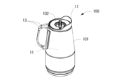
- FIG. 1 is a perspective view of a beverage container;
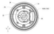
- FIG. 1 is a plan view of a beverage container;
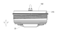
- FIG. Fig. 3 is a side view of the beverage container;
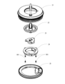
- 1 is an exploded perspective view of a beverage container;
- FIG. Figure 2 is a cross-sectional view of part of a beverage container;
- Figure 2 is a cross-sectional view of part of a beverage container;
- It is a perspective view of the cover part seen from the upper side.
- It is a perspective view of the cover part seen from the lower side.
- It is a front view of a cover part.
- It is a top view of a cover part.
- It is a bottom view of a cover part.
- It is a side view of a cover part.
- It is an exploded perspective view of a cover part.
- FIG. 4 is a perspective view of the adjustment member seen from above; FIG.
- FIG. 4 is a perspective view of the adjustment member seen from below; It is a top view of an adjusting member.
- FIG. 4 is a perspective view of the guide member as seen from above;
- FIG. 4 is a perspective view of the guide member viewed from below;
- It is a top view of a guide member.
- It is a perspective view of the connection member seen from the lower side.
- Fig. 10 is a perspective view of the second part seen from above;
- Fig. 10 is a perspective view of the second part seen from below;
- Fig. 10 is a front view of the second part;
- FIG. 11 is an exploded perspective view of the second portion viewed from above;
- FIG. 10 is an exploded perspective view of the second portion viewed from below;
- FIG. 4 is a perspective view of the partition member as seen from above;
- FIG. 10 is a perspective view of the partition member as seen from above;
- FIG. 10 is a perspective view of the partition member as seen from above;
- FIG. 10
- FIG. 4 is a perspective view of the partition member viewed from below; It is a perspective view of the member for movement seen from the upper side. It is a perspective view of the member for movement seen from the lower side.
- FIG. 4 is a side view of a moving member;
- Figure 2 is a cross-sectional view of part of a beverage container;
- Figure 2 is a cross-sectional view of part of a beverage container;
- Embodiments generally relate to beverage containers and lids.
- a “beverage container” is a container that holds a beverage.
- a “beverage” is something for drinking, and specifically, it is a concept that includes a liquid for drinking.
- the beverage contained in the beverage container is arbitrary, and for example, the concept includes sparkling beverages and other beverages (including non-sparkling beverages). Examples include carbonated beverages (including beer etc.), tea, This concept includes water, hot water, and the like.
- FIG. 1 is a perspective view of the beverage container
- FIG. 2 is a plan view of the beverage container
- FIG. 3 is a side view of the beverage container
- FIG. 4 is an exploded perspective view of the beverage container.
- 5 and 6 are cross-sectional views of a portion of the beverage container.
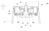
- FIG. 5 and 6 are cross-sectional views of the AA cross section of FIG. 2, and FIG. , and FIG. 6 illustrate the state in which these openings are open. 5 and 6, the hatching of a moving member 32, which will be described later, is partially omitted. 5 and 6, illustration of the handle 13 of FIG. 1 is omitted.
- the XYZ axes are orthogonal to each other, the Z axis indicates the vertical direction, and the X and Y axes indicate the horizontal direction.
- the +Z direction is also referred to as the upper side (top, plane), and the ⁇ Z direction is also referred to as the lower side (bottom, bottom).
- the +X direction is also called the front side, and the ⁇ X direction is also called the back side.
- the Y-axis direction is also called a side surface.
- a beverage container 100 in FIG. 1 is a container for containing a beverage (carbonated beverage in this embodiment), and includes, for example, a main body portion 101 and a lid portion 102 in FIG.
- the body portion 101 is a storage portion that stores a beverage, and specifically is a portion that becomes the main body of the beverage container 100 .
- the main body 101 has, for example, a circular shape as a whole in plan view, and includes a portion that is made of a metal such as stainless steel and has a vacuum insulation structure.
- the vacuum insulation structure is a concept that includes, for example, a structure in which walls dividing the inside and outside are doubled in order to enhance heat retention or cold retention.
- the body part 101 includes, for example, the hollow part 11 of FIG. 5, the spout 12 of FIG.
- a hollow portion 11 in FIG. 5 is a space formed inside the main body portion 101, and is a space for containing a beverage.
- the spout 12 in FIG. 1 is a part for pouring a beverage, and for example, as shown in FIG.
- the handle 13 in FIG. 1 is a part that serves as a handle for the user to hold the beverage container 100.
- This is the part provided.
- the main body side opening 14 in FIG. 4 is an opening for pouring a beverage into the main body 101, and is, for example, an opening that is circular in plan view and opened upward (+Z direction). , communicates with the hollow portion 11 of FIG.
- a lid portion 102 is detachably attached to the body portion side opening portion 14 .
- the main body side engaging portion 15 in FIG. 1 is a structure for attaching the lid portion 102 to the main body portion 101.
- the main body side engaging portion 15 in FIG. 1 is a structure for attaching the lid portion 102 to the main body portion 101.
- FIG. It is a screw groove with
- FIG. 7 is a perspective view of the lid viewed from above
- FIG. 8 is a perspective view of the lid viewed from below
- FIG. 9 is a front view of the lid
- FIG. 11 is a bottom view of the lid
- FIG. 12 is a side view of the lid
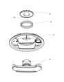
- FIG. 13 is an exploded perspective view of the lid.
- the lid portion 102 in FIG. 4 is provided on the upper portion (+Z direction) of the main body portion 101, and includes, for example, a mechanism that enables or disables the beverage contained in the main body portion 101 to be discharged. is.
- the lid portion 102 can discharge the beverage contained in the body portion 101 by, for example, opening the beverage opening 312 (FIG. 6) provided in the lower portion ( ⁇ Z direction) of the lid portion 102. It can be discharged to the outside through an outlet 215 (FIGS. 6 and 8). In this case, the gas opening 313 ( FIG. 6 ) is opened, and outside air is taken into the main body 101 through the gas opening 313 .
- the lid portion 102 discharges the beverage contained in the body portion 101 by, for example, closing the beverage opening 312 (FIG. 6) provided in the lower portion ( ⁇ Z direction) of the lid portion 102. Impossible. In this case, gas opening 313 (FIG. 5) is also closed.
- the lid portion 102 in FIGS. 7 to 12 is, for example, circular in plan view, and is made of resin, metal, or the like.
- the lid portion 102 includes a first portion 102A and a second portion 102B.
- Composition - Part 1 14 is a perspective view of the first portion seen from above
- FIG. 15 is a perspective view of the first portion seen from below
- FIG. 16 is a bottom view of the first portion
- FIG. 18 is an exploded perspective view of the first portion seen from above
- FIG. 18 is an exploded perspective view of the first portion seen from below.
- a first portion 102A in FIG. 13 is a portion that forms part of the upper side (+X direction) of the lid portion 102, and is, for example, a portion that is detachable from the second portion 102B.
- the first portion 102A includes, for example, a main body member 21, an operating member 22, an adjusting member 23, a guide member 24, and a connecting member 25, as shown in FIGS.
- FIG. 19 is a perspective view of the body member from above
- FIG. 20 is a perspective view of the body member from below
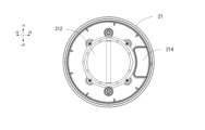
- FIG. 21 is a bottom view of the body member.
- the main body member 21 in FIGS. 17 to 21 is a member that forms the outer shape of the lid portion 102 and is a member that accommodates various components of the lid portion 102 .
- the main body member 21 is, for example, a circular member in a plan view, and is a member made of resin or the like as a whole.
- the body member 21 includes, for example, an upper handle 210 shown in FIG. 19, a lid side engaging portion 211 shown in FIG. Prepare.
- the upper handle 210 in FIG. 19 is a metal handle for the user to hold the lid portion 102, and is attached to a predetermined position of the main body member 21 by any method (for example, screwing method, etc.). It is
- (Configuration-first portion-main body member-lid portion side engaging portion) 19 and 20 is a structure for attaching the lid portion 102 to the body portion 101.
- the lid portion side engaging portion 211 shown in FIGS. be.
- the lid side engaging portion 211 is, for example, a screw thread provided on the outer surface of the main body member 21 .
- the opening 212 in FIGS. 19 to 21 is an opening for exposing a part of the operation member 22 (FIG. 17), and is, for example, a circular opening provided near the center of the body member 21. .
- a positioning recess 213 in FIG. 20 is a recess for positioning the rotational position of the operating member 22 (FIG. 17) with respect to the body member 21.
- FIG. 17 For example, as shown in FIG. It is a recess provided.
- two positioning recesses 213 are shown in FIG. 20, actually, the center of the main body member 21 in the horizontal direction is used as a reference, and the position on the opposite side of the two positioning recesses 213 in FIG. Two positioning recesses are provided, and a total of four positioning recesses are provided.
- Positioning the rotation position of the operation member 22 is, for example, a concept indicating positioning with respect to the angle of rotation of the operation member 22.
- the operation member 22 is rotated 90 degrees It is assumed that it indicates positioning to a position.
- a channel portion 214 in FIG. 20 is a space serving as a channel for discharging the beverage, and communicates with, for example, a discharge port 215 .
- a discharge port 215 in FIG. 20 is a through-hole for discharging the beverage, and is provided, for example, on the upper side (+Z direction) of the lid side engaging portion 211 in the main body member 21 .
- the body member side sealing material 216 in FIG. 20 is a packing or seal for maintaining watertightness and airtightness. 4) to prevent leakage to the side;
- the body member-side sealing material 216 is, for example, an annular one provided along the outer surface of the body member 21 .
- each sealing material described in the present embodiment can be arbitrarily configured as long as it is configured to prevent unexpected beverage or gas leakage in the beverage container 100. , size, or number may be changed arbitrarily. Also, each sealing material may be formed using rubber, or may be formed using any other material.
- (Configuration-first part-operation member) 22 is a perspective view of the operating member seen from above
- FIG. 23 is a perspective view of the operating member seen from below
- FIG. 24 is a plan view of the operating member.
- the 17 to 18 and 22 to 24 opens and closes the beverage opening 312 and the gas opening 313 (FIG. 6) to open and close the beverage opening 312 and the gas opening 313 (FIG. 6) when rotated by the user's operation.
- It is a member for making the dischargeable or non-dischargeable.
- the operation member 22 is, for example, a member that is housed in the main body member 21 and that is made of resin or the like.
- the operating member 22 includes, for example, a knob portion 221 shown in FIG. 22, a central projection portion 222 shown in FIG. 23, and a positioning projection portion 223.
- the knob portion 221 in FIGS. 22 and 24 is a portion that is gripped by the user and to which an external force for rotating is applied from the user. This is the portion exposed toward (+Z direction).
- the center-side projecting portion 222 in FIG. 23 is a portion projecting downward ( ⁇ Z direction), and has, for example, a screw thread 222A on its outer surface.
- the screw thread 222A is configured so that the adjustment member 23 (described later), which is screwed with the central protrusion 222 of the operation member 22 when the operation member 22 is rotated, is oriented upward (+Z direction) or downward ( ⁇ Z direction). It is spirally provided so that it can be moved.
- (Construction-first part-operation member-positioning protrusion) 22 to 24 is a portion for positioning the rotational position of the operating member 22 with respect to the main body member 21 (FIG. 20).
- the positioning protrusion 223 is configured to face the inner peripheral wall of the body member 21 provided with the positioning recess 213 (FIG. 20) when the operation member 22 is housed in the body member 21 .
- the positioning protrusion 223 protrudes facing the positioning recess 213, and the tip of the positioning protrusion 223 protrudes toward the positioning recess 213. It is provided within the recess 213 . Accordingly, the operating member 22 is positioned at the rotated position.
- the positioning protrusion 223 moves into the positioning recess 213 (rotation A positioning recess 213 provided next to the positioning recess 213 in which the positioning protrusion 223 was previously provided projects opposite to the positioning recess 213 ), and the tip of the positioning protrusion 223 is provided in the positioning recess 213 . Accordingly, the operating member 22 is positioned at the rotated position.
- the operating member 22 can be positioned by rotating it 90 degrees with respect to the main body member 21 .
- (Configuration-first part-adjustment member) 25 is a perspective view of the adjustment member seen from above
- FIG. 26 is a perspective view of the adjustment member seen from below
- FIG. 27 is a plan view of the adjustment member.
- the adjusting member 23 in FIGS. 17 to 18 and FIGS. 25 to 27 is a member for vertically moving the moving member 32 when the operating member 22 is rotated.
- the adjusting member 23 is, for example, a member accommodated in the main body member 21 and is a member formed of resin or the like.
- the adjustment member 23 includes, for example, an opening 231, a central protrusion 232, and a guide protrusion 233 shown in FIG. Note that "vertical movement” may be interpreted as, for example, moving upward (+Z direction) or downward (-Z direction).
- the opening 231 in FIGS. 25 to 27 is an opening through which the central protrusion 222 (FIG. 23) of the operating member 22 is passed, and communicates with the inner space of the central protrusion 232 of the adjusting member 23, for example. ing.
- the central projection 232 in FIG. 26 is a portion projecting downward ( ⁇ Z direction), for example, a hollow portion is provided, and a thread groove 232A is provided on the inner surface of the hollow portion. there is The screw groove 232A is spirally provided so as to be screwed with the screw thread 222A of the center-side projecting portion 222 of the operating member 22 (FIG. 23).
- Construction-first part-adjustment member-guide protrusion 25 to 27 is a portion for moving the adjusting member 23 up and down while preventing the rotation thereof.
- the guiding protrusion 233 protrudes outward from the center side of the adjusting member 23 in the horizontal direction. part.
- (Configuration-first part-guide member) 28 is a perspective view of the guide member seen from above
- FIG. 29 is a perspective view of the guide member seen from below
- FIG. 30 is a plan view of the guide member.
- the guide member 24 is, for example, a member that is housed in the main body member 21 and is a member made of resin or the like.
- the guide member 24 has, for example, an opening 241 shown in FIG. 28, a central projection 242, and a screw hole 243 shown in FIG.
- An opening 241 in FIGS. 28 to 30 is an opening in which at least part of the adjusting member 23 is provided, and is, for example, a circular opening provided near the center of the guide member 24 .
- Construction-first part-guide member-central protrusion 28 and 29 is a portion that protrudes downward (-Z direction), and is provided with a hollow portion, for example.
- a hollow portion of the center-side protruding portion 242 is, for example, a space in which the adjusting member 23 is provided, and a guide concave portion 242A is provided on the inner surface.
- the guide recess 242A is a recess for moving the adjustment member 23 up and down while preventing the rotation thereof, and is a recess in which the tip of the guide protrusion 233 (FIG. 25) of the adjustment member 23 is provided, for example.
- a screw hole 243 in FIGS. 29 and 30 is a screw hole for attaching and fixing the guide member 24 to the main body member 21, and for example, a screw hole into which the fixing screw 901 in FIGS. 17 and 18 is screwed. .
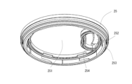
- FIG. 31 is a perspective view of the connecting member as seen from below.
- the connecting member 25 is, for example, a circular member in a plan view, and is a member made of resin or the like as a whole.
- the connecting member 25 includes, for example, a first opening 251, a second opening 252, a first connecting member side sealing material 253, and a second connecting member side sealing material 254 shown in FIG.
- a first opening 251 in FIG. 31 is an opening provided near the center of the connecting member 25 , for example, an opening provided next to the second opening 252 .
- the second opening 252 in FIG. 31 is an opening for discharging the beverage, for example, an opening maintained watertight with respect to the first opening 251 .
- the connecting member side first sealing material 253 in FIG. 31 is a packing or seal for maintaining watertightness and airtightness. This is for preventing leakage from between the portion 102 and the main body portion 101 .
- the connecting member-side first sealing member 253 is, for example, an annular member provided along the lower ( ⁇ Z direction) outer peripheral edge of the connecting member 25 .
- the connecting member side second sealing material 254 in FIG. 31 is packing or a seal for maintaining watertightness and airtightness. This is to prevent leakage.
- the connecting member side second sealing material 254 is provided, for example, in the lower part ( ⁇ Z direction) of the outer peripheral edges of the first opening 251 and the second opening 252 .
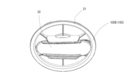
- Composition - Part 2 32 is a perspective view of the second portion seen from above
- FIG. 33 is a perspective view of the second portion seen from below
- FIG. 34 is a front view of the second portion
- FIG. 36 is an exploded perspective view of the second portion seen from above
- FIG. 36 is an exploded perspective view of the second portion seen from below.
- a second portion 102B in FIG. 13 is a portion that forms a portion of the lower side (+X direction) of the lid portion 102, and is, for example, a portion that is detachable from the first portion 102A.
- the second portion 102B includes, for example, a partition member 31, a moving member 32, a biasing member 33, and a mounting member 34, as shown in FIGS.
- FIG. 38 is a perspective view of the partition member seen from below.
- a partition member 31 in FIGS. 37 and 38 is a member that separates the inside and outside of the main body 101 at the main body side opening 14 in FIG.
- the partition member 31 is, for example, a circular member in plan view, and is a plate-like member made of resin or the like as a whole.
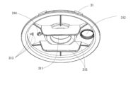
- the partition member 31 includes, for example, a central opening 311 in FIG. 37, a beverage opening 312, a gas opening 313, a pressure reducing valve 314, and a guide portion 315 in FIG.
- the central opening 311 in FIGS. 37 and 38 is an opening through which the central protrusion 322 (described later) of the moving member 32 is passed, and is provided at the center of the partition member 31 in the horizontal direction, for example. It is an opening.
- a beverage opening 312 in FIGS. 37 and 38 is an opening for discharging the beverage from the main body 101, and is, for example, a circular opening with a predetermined diameter.
- a gas opening 313 in FIGS. 37 and 38 is an opening for taking outside air into the main body 101 .
- the gas opening 313 is provided with the center of the partition member 31 in the horizontal direction (that is, the center side opening 311) as a reference. It is provided at a position opposite to the installation position of the opening 312 .
- the configurations of the gas opening 313 and the beverage opening 312 can be arbitrarily changed, for example, the shape, size, number, installation position, etc. of the openings may be arbitrarily changed.
- a pressure reducing valve 314 in FIGS. 37 and 38 is pressure reducing means for reducing the pressure in the main body 101 .
- the hollow portion 11 ( FIG. 5 ) of the main body portion 101 is kept watertight and airtight. However, since the pressure reducing valve 314 is provided, the pressure in the hollow portion 11 can be appropriately reduced and maintained at a predetermined pressure or less or at a predetermined pressure.
- the type and configuration of the pressure reducing valve 314 are arbitrary. It can be configured using known pressure reducing valve technology.
- the guide portion 315 in FIG. 38 is a portion for guiding the vertical movement of the moving member 32, and is, for example, a portion protruding downward ( ⁇ Z direction) from both sides of the central opening 311. .
- FIG. 39 is a perspective view of the moving member seen from above
- FIG. 40 is a perspective view of the moving member seen from below
- FIG. 41 is a side view of the moving member.
- the beverage opening/closing portion side sealing member 324 and the gas opening/closing portion side sealing member 325 up and down so that the beverage opening of FIG. 6 is moved by the respective sealing members.
- It is a member that opens and closes the portion 312 and the gas opening portion 313, and for example, is a member made of resin or the like as a whole.
- the moving member 32 is partly exposed below the lid 102 (-Z direction).
- the moving member 32 includes, for example, a body portion 321, a center-side projecting portion 322, a fixing piece 323, a beverage opening/closing portion-side sealing member 324, a gas opening/closing portion-side sealing member 325, and a protrusion-side sealing member, as shown in FIG. A stop member 326 is provided.
- a body portion 321 in FIGS. 39 to 41 is a portion extending in the horizontal direction.
- the fixing piece 323 in FIGS. 39 to 41 is a portion to which the mounting member 34 that is biased upward (+Z direction) by the biasing member 33 is fixed and attached. .
- the beverage opening/closing part side sealing material 324 is a beverage opening/closing part that opens and closes the beverage opening 312 shown in FIG. 6 or 37 from below (-Z direction) the beverage opening 312. Specifically, it is a member that blocks and closes the beverage opening 312 or opens the beverage opening 312 .
- the beverage opening/closing part side sealing material 324 is a packing or a seal for maintaining watertightness and airtightness, and for example, protrudes upward (+Z direction) at the front side (+X direction) end of the main body part 321. It has a larger diameter than the beverage opening 312 in plan view.
- the gas opening/closing unit side sealing material 325 is a packing or seal for maintaining watertightness and airtightness. It stands out. Further, the gas opening/closing part side sealing material 325 has a diameter capable of closing all the gas openings 313 (FIG. 37), for example.
- (Configuration-second part-moving member-projection side sealing material) 39 to 41 is a packing or seal for maintaining watertightness and airtightness. This is to prevent the beverage and gas contained in the portion 11 ( FIG. 5 ) from leaking from between the center-side projecting portion 322 of the moving member 32 and the partition member 31 .
- the protrusion-side sealing material 326 is, for example, an annular ring provided along the outer surface of the center-side protrusion 322 toward the lower side ( ⁇ Z direction).
- body portion 321 and the center-side projecting portion 322 in the moving member 32 may be interpreted as corresponding to the "moving member”.
- the biasing member 33 in FIGS. 35 and 36 is a member that biases and pushes the moving member 32 upward (+Z direction) with respect to the partition member 31 via the mounting member 34.
- a spring It can be configured using an element having elasticity such as.
- the biasing member 33 is provided between the partition member 31 and the mounting member 34 in the vertical direction (Z-axis direction).
- the mounting member 34 shown in FIGS. 35 and 36 is a member for mounting the biasing member 33 to the moving member 32.
- the mounting member 34 is circular in plan view and made of resin or the like. be.
- the mounting member 34 has, for example, an opening 341 and a fixing recess 342 shown in FIG.
- An opening 341 in FIGS. 35 and 36 is an opening through which the upper end (+Z direction) of the central protrusion 322 of the moving member 32 is passed. It is an opening with
- the fixing recess 342 in FIG. 35 is a portion to which the fixing piece 323 of the moving member 32 is fixed from the upper side (+Z direction). This is the part where
- the adjusting member 23 is attached to the operating member 22 in FIGS.
- the central projection 222 of the operating member 22 of FIG. 23 is provided inside the central projection 232 through the opening 231 of the adjusting member 23 of FIG.
- the screw thread 222A of the operating member 22 in FIG. 23 is provided in the thread groove 232A of the adjusting member 23 in FIG. .
- these operating member 22 and adjusting member 23 are attached to the body member 21 using the guide member 24 shown in FIGS.
- the guide member 24 shown in FIGS. For example, by providing the adjustment member 23 inside the center side protrusion 242 of the guide member 24 of FIG. 28, the guide protrusion 233 of the adjustment member 23 of FIG. .
- the fixing screw 901 shown in FIGS. 17 and 18 is continuously screwed into the screw hole 243 of the guide member 24 shown in FIG. 29 and the screw hole of the body member 21 shown in FIGS. .
- each member is provided with an engaging structure that enables these members to be detachably attached to each other, and this engaging structure is used for attachment. good too. This completes the assembly of the first portion 102A of the lid portion 102 of FIGS. 14-16.
- the moving member 32 shown in FIGS. 35 and 66 is provided on the partition member 31 .
- the central protrusion 322 of the moving member 32 of FIG. 39 is provided through the central opening 311 of the partition member 31 of FIG.
- the biasing member 33 shown in FIGS. 35 and 36 is provided.
- the biasing member 33 shown in FIG. Install a certain spring.
- the lower end portion ( ⁇ Z direction) of the biasing member 33 is placed on the portion of the partition member 31 surrounding the central opening 311 .
- the mounting member 34 shown in FIGS. 35 and 36 is mounted.
- the center-side projecting portion 322 of the moving member 32 is pressed against the opening portion 341 of the mounting member 34 .
- the fixing piece 323 of the moving member 32 is provided in the fixing concave portion 342 of the mounting member 34 by inserting the upper side (+Z direction) of the mounting member 34 and rotating the mounting member 34 .
- the spring which is the biasing member 33, is provided between the partition member 31 and the mounting member 34 in a compressed state. This completes the assembly of the second portion 102B of the lid portion 102 of FIGS. 32-34.
- each part is provided with an engaging structure that enables these parts to be detachably attached to each other, and this engaging structure is used for attachment. good too. This completes the assembly of the lid portion 102 shown in FIGS.
- the center-side projecting portion 222 of the operating member 22 also rotates 90 degrees in one direction.
- the adjustment member 23 screwed to the central protrusion 222 is provided with the guide protrusion 233 of FIG. 25 in the guide recess 242A of the guide member 24 of FIG. Based on this, for example, it moves downward (-Z direction) and protrudes.
- the center-side projecting portion 222 of the operating member 22 also turns 90 degrees around the other side.
- the adjustment member 23 screwed to the central protrusion 222 is provided with the guide protrusion 233 of FIG. 25 in the guide recess 242A of the guide member 24 of FIG. Based on this, for example, it moves upward (+Z direction) and retreats.
- the mounting member 34 moves upward (+Z direction) with respect to the partition member 31 due to the biasing force of the biasing member 33 in FIG.
- the fixing piece 323 of the moving member 32 is provided on the upper surface of the mounting member 34 (more specifically, the fixing concave portion 342 (FIG. 35))
- the fixing piece 323 is moved upward (in the +Z direction) by the mounting member 34. ) to move the moving member 32 upward (+Z direction).
- the beverage opening/closing portion side sealing member 324 (FIG. 41) and the gas opening/closing portion side sealing member 325 of the moving member 32 move from below the partition member 31 ( ⁇ Z direction). are pressed to positions corresponding to the opening 312 for gas and the opening 313 for gas, and the respective openings are closed by the respective sealing materials. That is, the beverage opening 312 and the gas opening 313 are blocked and closed at the same time.
- the moving member 32 moves against the biasing force of the biasing member 33 shown in FIG. will move downwards.
- the beverage opening/closing portion side sealing member 324 (FIG. 41) and the gas opening/closing portion side sealing member 325 of the moving member 32 are separated from the partition member 31, the beverage opening portion 312 and the gas opening portion are separated from each other. 313 is vacated. That is, the beverage opening 312 and the gas opening 313 are emptied and opened at the same time.
- FIGS. 7 to 12 are cross-sectional views of a portion of the beverage container. 42 and 43 are cross-sectional views similar to FIGS. 5 and 6. FIG.
- the adjusting member 23 moves downward (-Z direction) as described above.
- the moving member 32 is pushed by the adjusting member 23 to move downward ( ⁇ Z direction), and the beverage opening/closing portion side sealing material 324 and the gas Since the opening/closing section side sealing material 325 is separated from the partition member 31, the beverage opening 312 and the gas opening 313 are opened.
- each sealing material where the opening/closing part side sealing material 324 for beverage and the opening/closing part side sealing material 325 for gas are separated from the partition member 31 and each opening is open may be interpreted as corresponding to "the second position on the opening/closing member side for beverage” and "the second position on the side of the opening/closing member for gas".
- the adjusting member 23 moves upward (+Z direction) as described above.
- the opening/closing part side sealing member 325 is pressed against the partition member 31, the beverage opening 312 and the gas opening 313 are blocked and closed.
- the positions of the respective sealing members corresponds to the "opening/closing member side first position for beverage" and the "opening/closing member side first position for gas".
- the lid portion 102 is removed from the main body portion 101, and the beverage is put into the hollow portion 11 of the main body portion 101 through the main body side opening 14 and stored. Next, the lid portion 102 is attached to the body portion 101 .
- the operation member 22 is rotated 90 degrees in the other direction to block and close the opening 312 for beverage and the opening 313 for gas.
- the beverage opening 312 and the gas opening 313 are closed, and watertightness and airtightness are maintained. Therefore, even if the beverage container 100 is tilted, the beverage contained in the hollow portion 11 is not discharged. It will be. Also, since the beverage is a carbonated beverage, the beverage foams and the pressure inside the hollow portion 11 increases. Therefore, the pressure inside the hollow portion 11 can be maintained at a predetermined pressure level. Further, since the beverage opening/closing part side sealing material 324 and the gas opening/closing part side sealing material 325 close the respective openings from the lower side of the partition member 31, even if the pressure in the hollow part 11 increases, It is possible to reliably maintain the closed state of the opening.
- the operating member 22 is rotated 90 degrees in one direction to open the beverage opening 312 and the gas opening 313 .
- the hollow portion 11 of the main body portion 101 communicates with the discharge port 215 via the beverage opening portion 312 and the flow path portion 214, so that when the beverage container 100 is tilted, The contained beverage can be discharged from the vicinity of the spout 12 in FIG.
- the gas opening 313 is open, the outside air enters the hollow portion 11 through the gas opening 313 and the internal space 21A (FIG. 43) of the lid 102, which is not airtight.
- the beverage can be reliably discharged from the beverage opening 312 side.
- the internal space 21A outside air is taken in through gaps between parts that are not airtight (for example, a gap between the main body member 21 and the operation member 22 or the adjustment member 23). .
- the beverage opening/closing portion side sealing member 324 that opens and closes the beverage opening 312 from the lower side of the beverage opening 312, for example, the user's intention can be to make the beverage drainable or non-drainable.
- the beverage can be discharged through the gas opening 313. can be prevented.
- the beverage opening/closing part side sealing material 324 is moved to the beverage opening/closing member side first position, and the gas opening/closing part side sealing material 325 is moved to the gas opening/closing member side first position, or
- By moving the beverage opening/closing part side sealing material 324 to the beverage opening/closing member side second position and moving the gas opening/closing part side sealing material 325 to the gas opening/closing member side second position for example, Since outside air can be taken in when the beverage is discharged, the beverage can be discharged smoothly. Also, for example, both openings can be closed, so it is possible to reliably prevent the beverage from being discharged.
- the beverage is a fizzy beverage
- the beverage opening/closing portion side sealing material 324 shifts against the user's intention and the beverage opening 312 opens based on the pressure. Since this can be prevented, it is possible to reliably make the beverage dischargeable or non-dischargeable according to the user's intention.
- each component of the lid portion 102 of the above-described embodiment is arbitrary. Alternatively, it may be configured to be fixed and attached with an adhesive or the like.
- each member described in the above embodiment may be configured integrally.
- the body member 21 and the connecting member 25 of FIG. 17 may be integrally configured.
- the beverage container according to Appendix 1 includes a storage portion that stores a beverage, and a lid portion that is provided on an upper portion of the storage portion.
- the beverage container according to Appendix 2 is the beverage container according to Appendix 1, wherein the lid portion is a gas opening for taking in outside air into the inside of the storage portion when the beverage stored in the storage portion is discharged. It further comprises the gas opening provided separately from the beverage opening, and a gas opening/closing member that opens and closes the gas opening from below the gas opening.
- the beverage container according to Supplementary Note 3 is the beverage container according to Supplementary Note 2, wherein the beverage opening/closing member is located at a first position on the beverage opening/closing member side at which the beverage opening is closed by covering the beverage opening, and The gas opening/closing member is movable to a second position on the beverage opening/closing member side that opens, and the gas opening/closing member has a first position on the gas opening/closing member side that blocks and closes the gas opening, and a first position on the gas opening/closing member side that closes the gas opening.
- the lid portion includes a moving member that moves the beverage opening/closing member and the gas opening/closing member in synchronization with each other, and the moving member is moving the opening/closing member for beverage to the first position on the side of the opening/closing member for beverage and moving the opening/closing member for gas to the first position on the side of the opening/closing member for gas;
- the beverage opening/closing member side is moved to the second position, and the gas opening/closing member is moved to the gas opening/closing member side second position.
- the beverage container of Appendix 4 is the beverage container according to any one of Appendixes 1 to 3, wherein the lid portion further includes decompression means for reducing the pressure in the accommodating portion.
- the beverage container of Appendix 5 is the beverage container according to any one of Appendixes 1 to 4, wherein the beverage is a sparkling beverage.
- the lid portion according to Supplementary Note 6 is a lid portion of a beverage container including a storage portion that stores a beverage and a lid portion that is provided at the top of the storage portion, and is housed in the storage portion. and a beverage opening and closing member for opening and closing the beverage opening from below the beverage opening.
- the beverage is discharged through the gas opening, for example, by providing the gas opening/closing member that opens and closes the gas opening from the lower side of the gas opening. It is possible to prevent this.
- the beverage opening/closing member is moved to the beverage opening/closing member side first position, and the gas opening/closing member is moved to the gas opening/closing member side first position, or
- By moving the opening/closing member for beverage to the second position on the side of the opening/closing member for beverage and moving the opening/closing member for gas to the second position on the side of the opening/closing member for gas for example, outside air can be taken in when the beverage is discharged. Therefore, the beverage can be discharged smoothly. Also, for example, both openings can be closed, so it is possible to reliably prevent the beverage from being discharged.
- the beverage container described in appendix 5 since the beverage is a sparkling beverage, it is possible, for example, to make the sparkling beverage dischargeable or undischargeable according to the user's intention.
- the pressure inside the container rises due to foaming of the beverage, it is possible to prevent the opening for beverage from opening due to the deviation of the opening and closing member for beverage against the user's intention based on the pressure.
Landscapes
- Engineering & Computer Science (AREA)
- Mechanical Engineering (AREA)
- Physics & Mathematics (AREA)
- Thermal Sciences (AREA)
- Food Science & Technology (AREA)
- Health & Medical Sciences (AREA)
- General Health & Medical Sciences (AREA)
- Pediatric Medicine (AREA)
- Closures For Containers (AREA)
- Table Devices Or Equipment (AREA)
Priority Applications (7)
| Application Number | Priority Date | Filing Date | Title |
|---|---|---|---|
| GB2306616.0A GB2615265A (en) | 2021-10-21 | 2021-10-21 | Beverage container and lid part |
| KR1020227041583A KR20240083119A (ko) | 2021-10-21 | 2021-10-21 | 음료 용기 및 뚜껑부 |
| PCT/JP2021/038919 WO2023067756A1 (ja) | 2021-10-21 | 2021-10-21 | 飲料容器、及び蓋部 |
| CN202180029362.1A CN118234667B (zh) | 2021-10-21 | 2021-10-21 | 饮料容器和盖体 |
| JP2023554174A JPWO2023067756A1 (https=) | 2021-10-21 | 2021-10-21 | |
| TW111132790A TWI921598B (zh) | 2021-10-21 | 2022-08-30 | 飲料容器及其蓋體 |
| US17/954,812 US12290191B2 (en) | 2021-10-21 | 2022-09-28 | Beverage container and lid portion |
Applications Claiming Priority (1)
| Application Number | Priority Date | Filing Date | Title |
|---|---|---|---|
| PCT/JP2021/038919 WO2023067756A1 (ja) | 2021-10-21 | 2021-10-21 | 飲料容器、及び蓋部 |
Related Child Applications (1)
| Application Number | Title | Priority Date | Filing Date |
|---|---|---|---|
| US17/954,812 Continuation-In-Part US12290191B2 (en) | 2021-10-21 | 2022-09-28 | Beverage container and lid portion |
Publications (1)
| Publication Number | Publication Date |
|---|---|
| WO2023067756A1 true WO2023067756A1 (ja) | 2023-04-27 |
Family
ID=86055347
Family Applications (1)
| Application Number | Title | Priority Date | Filing Date |
|---|---|---|---|
| PCT/JP2021/038919 Ceased WO2023067756A1 (ja) | 2021-10-21 | 2021-10-21 | 飲料容器、及び蓋部 |
Country Status (6)
| Country | Link |
|---|---|
| US (1) | US12290191B2 (https=) |
| JP (1) | JPWO2023067756A1 (https=) |
| KR (1) | KR20240083119A (https=) |
| CN (1) | CN118234667B (https=) |
| GB (1) | GB2615265A (https=) |
| WO (1) | WO2023067756A1 (https=) |
Citations (3)
| Publication number | Priority date | Publication date | Assignee | Title |
|---|---|---|---|---|
| US20180065784A1 (en) * | 2014-11-04 | 2018-03-08 | Klean Kanteen, Inc. | Container sealing assembly |
| US20200055646A1 (en) * | 2016-11-01 | 2020-02-20 | Igloo Products Corp. | Container lid |
| JP2020171369A (ja) * | 2019-04-08 | 2020-10-22 | タイガー魔法瓶株式会社 | 液体容器 |
Family Cites Families (12)
| Publication number | Priority date | Publication date | Assignee | Title |
|---|---|---|---|---|
| US3739938A (en) * | 1971-05-20 | 1973-06-19 | N Paz | Non-spill cup |
| US5037015A (en) * | 1987-03-23 | 1991-08-06 | Service Ideas, Inc. | Cap with integral pouring spout for pitchers |
| JPH0616569Y2 (ja) * | 1988-09-09 | 1994-05-02 | 象印マホービン株式会社 | 液体容器の栓 |
| EP2016004B1 (en) * | 2006-04-24 | 2010-08-18 | Giorgio Tosini | Protecting membrane for a vessel adapted for cooking, freezing or storing foodstuff |
| JP5874371B2 (ja) * | 2011-12-14 | 2016-03-02 | タイガー魔法瓶株式会社 | 液体容器 |
| JP5354063B1 (ja) * | 2012-06-04 | 2013-11-27 | サーモス株式会社 | 飲料容器の栓体 |
| JP5457523B2 (ja) * | 2012-08-02 | 2014-04-02 | サーモス株式会社 | 飲料容器の栓体 |
| JP6526601B2 (ja) * | 2016-05-16 | 2019-06-05 | 象印マホービン株式会社 | 飲料容器 |
| US20180118417A1 (en) * | 2016-10-31 | 2018-05-03 | Alfay Designs | Leak-Proof Push Button Lid |
| US10926924B2 (en) * | 2018-05-17 | 2021-02-23 | Helen Of Troy Limited | Drink container lid assembly |
| JP7470585B2 (ja) | 2019-12-27 | 2024-04-18 | サーモス株式会社 | ピッチャー |
| US20210300661A1 (en) * | 2020-03-27 | 2021-09-30 | Sunbeam Products, Inc. | Valve assembly for a food storage container |
-
2021
- 2021-10-21 JP JP2023554174A patent/JPWO2023067756A1/ja active Pending
- 2021-10-21 KR KR1020227041583A patent/KR20240083119A/ko active Pending
- 2021-10-21 CN CN202180029362.1A patent/CN118234667B/zh active Active
- 2021-10-21 GB GB2306616.0A patent/GB2615265A/en active Pending
- 2021-10-21 WO PCT/JP2021/038919 patent/WO2023067756A1/ja not_active Ceased
-
2022
- 2022-09-28 US US17/954,812 patent/US12290191B2/en active Active
Patent Citations (3)
| Publication number | Priority date | Publication date | Assignee | Title |
|---|---|---|---|---|
| US20180065784A1 (en) * | 2014-11-04 | 2018-03-08 | Klean Kanteen, Inc. | Container sealing assembly |
| US20200055646A1 (en) * | 2016-11-01 | 2020-02-20 | Igloo Products Corp. | Container lid |
| JP2020171369A (ja) * | 2019-04-08 | 2020-10-22 | タイガー魔法瓶株式会社 | 液体容器 |
Also Published As
| Publication number | Publication date |
|---|---|
| GB202306616D0 (en) | 2023-06-21 |
| TW202320673A (zh) | 2023-06-01 |
| GB2615265A (en) | 2023-08-02 |
| CN118234667A (zh) | 2024-06-21 |
| US12290191B2 (en) | 2025-05-06 |
| JPWO2023067756A1 (https=) | 2023-04-27 |
| US20230128545A1 (en) | 2023-04-27 |
| CN118234667B (zh) | 2026-02-27 |
| KR20240083119A (ko) | 2024-06-11 |
Similar Documents
| Publication | Publication Date | Title |
|---|---|---|
| KR100593246B1 (ko) | 용기 | |
| KR101182011B1 (ko) | 토출용기 | |
| KR20170007354A (ko) | 컨테이너를 위한 어드믹서-폐쇄 디바이스 | |
| AU2014300355A1 (en) | Double-walled container | |
| US10723537B2 (en) | Cartridge pump | |
| EP3263512B1 (en) | Container for liquids associated with a carbonator | |
| JP6310838B2 (ja) | スクイズ容器 | |
| WO2023067756A1 (ja) | 飲料容器、及び蓋部 | |
| WO2015178190A1 (ja) | 開閉弁、スパウトおよび液体収容器 | |
| US7127912B2 (en) | Multi-chambered container with collared O-ring | |
| US11045774B2 (en) | Container for liquids associated with a carbonator | |
| TWI921598B (zh) | 飲料容器及其蓋體 | |
| KR20040074164A (ko) | 내용물 배출구조를 개선시킨 자동혼합 화장품 용기 | |
| WO2010004252A2 (en) | Closure element a fluid container | |
| ES2330213T3 (es) | Dispositivo de dispensacion. | |
| US20050087567A1 (en) | Dispensing device | |
| KR200315702Y1 (ko) | 음료용기의 마개 | |
| KR20030027931A (ko) | 음료용기의 마개 | |
| JP2013103738A (ja) | 混合容器 | |
| JP7082412B2 (ja) | 飲料用補助コック | |
| KR200354814Y1 (ko) | 두 종류의 내용물을 혼합할 수 있는 이중용기 | |
| JP3255012U (ja) | コック付きキャップ | |
| KR200347140Y1 (ko) | 음료용기용 원터치형 캡 | |
| KR200197302Y1 (ko) | 액상물질 저장용기용 마개 | |
| KR200471803Y1 (ko) | 상하부 분할판을 갖는 이액형 혼합 화장용기 |
Legal Events
| Date | Code | Title | Description |
|---|---|---|---|
| WWE | Wipo information: entry into national phase |
Ref document number: 202180029362.1 Country of ref document: CN |
|
| ENP | Entry into the national phase |
Ref document number: 202306616 Country of ref document: GB Kind code of ref document: A Free format text: PCT FILING DATE = 20211021 |
|
| WWE | Wipo information: entry into national phase |
Ref document number: 2306616.0 Country of ref document: GB |
|
| 121 | Ep: the epo has been informed by wipo that ep was designated in this application |
Ref document number: 21961408 Country of ref document: EP Kind code of ref document: A1 |
|
| WWP | Wipo information: published in national office |
Ref document number: 2306616.0 Country of ref document: GB |
|
| WWE | Wipo information: entry into national phase |
Ref document number: 2023554174 Country of ref document: JP |
|
| NENP | Non-entry into the national phase |
Ref country code: DE |
|
| 122 | Ep: pct application non-entry in european phase |
Ref document number: 21961408 Country of ref document: EP Kind code of ref document: A1 |