WO2023058597A1 - 放熱部材 - Google Patents
放熱部材 Download PDFInfo
- Publication number
- WO2023058597A1 WO2023058597A1 PCT/JP2022/036939 JP2022036939W WO2023058597A1 WO 2023058597 A1 WO2023058597 A1 WO 2023058597A1 JP 2022036939 W JP2022036939 W JP 2022036939W WO 2023058597 A1 WO2023058597 A1 WO 2023058597A1
- Authority
- WO
- WIPO (PCT)
- Prior art keywords
- metal
- hole
- silicon carbide
- heat dissipating
- dissipating member
- Prior art date
- Legal status (The legal status is an assumption and is not a legal conclusion. Google has not performed a legal analysis and makes no representation as to the accuracy of the status listed.)
- Ceased
Links
Images


Classifications
-
- H—ELECTRICITY
- H10—SEMICONDUCTOR DEVICES; ELECTRIC SOLID-STATE DEVICES NOT OTHERWISE PROVIDED FOR
- H10W—GENERIC PACKAGES, INTERCONNECTIONS, CONNECTORS OR OTHER CONSTRUCTIONAL DETAILS OF DEVICES COVERED BY CLASS H10
- H10W40/00—Arrangements for thermal protection or thermal control
- H10W40/10—Arrangements for heating
-
- H—ELECTRICITY
- H05—ELECTRIC TECHNIQUES NOT OTHERWISE PROVIDED FOR
- H05K—PRINTED CIRCUITS; CASINGS OR CONSTRUCTIONAL DETAILS OF ELECTRIC APPARATUS; MANUFACTURE OF ASSEMBLAGES OF ELECTRICAL COMPONENTS
- H05K7/00—Constructional details common to different types of electric apparatus
- H05K7/20—Modifications to facilitate cooling, ventilating, or heating
- H05K7/2039—Modifications to facilitate cooling, ventilating, or heating characterised by the heat transfer by conduction from the heat generating element to a dissipating body
-
- H—ELECTRICITY
- H10—SEMICONDUCTOR DEVICES; ELECTRIC SOLID-STATE DEVICES NOT OTHERWISE PROVIDED FOR
- H10W—GENERIC PACKAGES, INTERCONNECTIONS, CONNECTORS OR OTHER CONSTRUCTIONAL DETAILS OF DEVICES COVERED BY CLASS H10
- H10W40/00—Arrangements for thermal protection or thermal control
- H10W40/20—Arrangements for cooling
- H10W40/22—Arrangements for cooling characterised by their shape, e.g. having conical or cylindrical projections
- H10W40/226—Arrangements for cooling characterised by their shape, e.g. having conical or cylindrical projections characterised by projecting parts, e.g. fins to increase surface area
- H10W40/228—Arrangements for cooling characterised by their shape, e.g. having conical or cylindrical projections characterised by projecting parts, e.g. fins to increase surface area the projecting parts being wire-shaped or pin-shaped
-
- H—ELECTRICITY
- H10—SEMICONDUCTOR DEVICES; ELECTRIC SOLID-STATE DEVICES NOT OTHERWISE PROVIDED FOR
- H10W—GENERIC PACKAGES, INTERCONNECTIONS, CONNECTORS OR OTHER CONSTRUCTIONAL DETAILS OF DEVICES COVERED BY CLASS H10
- H10W40/00—Arrangements for thermal protection or thermal control
- H10W40/20—Arrangements for cooling
- H10W40/25—Arrangements for cooling characterised by their materials
-
- H—ELECTRICITY
- H10—SEMICONDUCTOR DEVICES; ELECTRIC SOLID-STATE DEVICES NOT OTHERWISE PROVIDED FOR
- H10W—GENERIC PACKAGES, INTERCONNECTIONS, CONNECTORS OR OTHER CONSTRUCTIONAL DETAILS OF DEVICES COVERED BY CLASS H10
- H10W40/00—Arrangements for thermal protection or thermal control
- H10W40/20—Arrangements for cooling
- H10W40/25—Arrangements for cooling characterised by their materials
- H10W40/253—Semiconductors
-
- H—ELECTRICITY
- H10—SEMICONDUCTOR DEVICES; ELECTRIC SOLID-STATE DEVICES NOT OTHERWISE PROVIDED FOR
- H10W—GENERIC PACKAGES, INTERCONNECTIONS, CONNECTORS OR OTHER CONSTRUCTIONAL DETAILS OF DEVICES COVERED BY CLASS H10
- H10W40/00—Arrangements for thermal protection or thermal control
- H10W40/20—Arrangements for cooling
- H10W40/25—Arrangements for cooling characterised by their materials
- H10W40/255—Arrangements for cooling characterised by their materials having a laminate or multilayered structure, e.g. direct bond copper [DBC] ceramic substrates
-
- H—ELECTRICITY
- H10—SEMICONDUCTOR DEVICES; ELECTRIC SOLID-STATE DEVICES NOT OTHERWISE PROVIDED FOR
- H10W—GENERIC PACKAGES, INTERCONNECTIONS, CONNECTORS OR OTHER CONSTRUCTIONAL DETAILS OF DEVICES COVERED BY CLASS H10
- H10W40/00—Arrangements for thermal protection or thermal control
- H10W40/20—Arrangements for cooling
- H10W40/25—Arrangements for cooling characterised by their materials
- H10W40/258—Metallic materials
-
- H—ELECTRICITY
- H10—SEMICONDUCTOR DEVICES; ELECTRIC SOLID-STATE DEVICES NOT OTHERWISE PROVIDED FOR
- H10W—GENERIC PACKAGES, INTERCONNECTIONS, CONNECTORS OR OTHER CONSTRUCTIONAL DETAILS OF DEVICES COVERED BY CLASS H10
- H10W40/00—Arrangements for thermal protection or thermal control
- H10W40/20—Arrangements for cooling
- H10W40/25—Arrangements for cooling characterised by their materials
- H10W40/259—Ceramics or glasses
-
- H—ELECTRICITY
- H10—SEMICONDUCTOR DEVICES; ELECTRIC SOLID-STATE DEVICES NOT OTHERWISE PROVIDED FOR
- H10W—GENERIC PACKAGES, INTERCONNECTIONS, CONNECTORS OR OTHER CONSTRUCTIONAL DETAILS OF DEVICES COVERED BY CLASS H10
- H10W40/00—Arrangements for thermal protection or thermal control
- H10W40/60—Securing means for detachable heating or cooling arrangements, e.g. clamps
- H10W40/611—Bolts or screws
-
- H—ELECTRICITY
- H10—SEMICONDUCTOR DEVICES; ELECTRIC SOLID-STATE DEVICES NOT OTHERWISE PROVIDED FOR
- H10W—GENERIC PACKAGES, INTERCONNECTIONS, CONNECTORS OR OTHER CONSTRUCTIONAL DETAILS OF DEVICES COVERED BY CLASS H10
- H10W40/00—Arrangements for thermal protection or thermal control
- H10W40/20—Arrangements for cooling
- H10W40/22—Arrangements for cooling characterised by their shape, e.g. having conical or cylindrical projections
-
- H—ELECTRICITY
- H10—SEMICONDUCTOR DEVICES; ELECTRIC SOLID-STATE DEVICES NOT OTHERWISE PROVIDED FOR
- H10W—GENERIC PACKAGES, INTERCONNECTIONS, CONNECTORS OR OTHER CONSTRUCTIONAL DETAILS OF DEVICES COVERED BY CLASS H10
- H10W90/00—Package configurations
Definitions
- the present invention relates to heat dissipation members.
- Patent Document 1 discloses an Al—SiC composite body formed by impregnating a silicon carbide porous body with aluminum, a fixing hole penetrating the Al—SiC composite body, the inner surface of the fixing hole, and the Al—SiC and an aluminum coating layer formed over the entire outer peripheral edge of the composite main body (Patent Document 1, FIG. 2, paragraph 0012, etc.).
- the present inventor found that by forming a screw hole in a metal portion containing aluminum in a through hole having a tapered portion, it is possible to improve the easiness of screw tightening in such a screw hole.
- the discovery led to the completion of the present invention.
- the following heat radiating member comprising a flat metal-silicon carbide composite containing aluminum, at least one or more through-holes penetrating the plate-like metal-silicon carbide composite in the plate thickness direction; a tapered portion around one or both ends of the through-hole, wherein the inner diameter of the through-hole gradually widens toward the outside; a metal portion containing aluminum formed on the inner surface of the through hole; a screw hole formed in the metal portion; A heat dissipation member.
- the heat dissipating member according to A heat radiating member wherein D2/D1 satisfies 0.1 or more and 0.9 or less, where D1 is the maximum hole diameter of the through holes and D2 is the hole diameter of the screw holes. 4. 1. ⁇ 3.
- a heat dissipating member according to In a cross-sectional view of the through hole where W1 is the thickness of the metal portion and W2 is the thickness of the plated layer inside the screw hole, W2/W1 satisfies 0.001 or more and 0.04 or less. heat dissipating member. 6. 1. ⁇ 5.
- the heat dissipating member according to any one of A heat dissipating member comprising a plating layer provided on a main surface side of the heat dissipating member. 7. 6. A heat dissipating member according to The heat dissipating member, wherein the plated layer is composed of a Ni plated layer containing Ni element. 8. 1. ⁇ 7. The heat dissipating member according to any one of A heat dissipating member comprising a metal layer containing aluminum provided on a main surface of the heat dissipating member. 9. 1. ⁇ 8. The heat dissipating member according to any one of A heat dissipating member having an average thermal expansion coefficient from 25° C. to 150° C.
- a heat dissipating member is provided that is excellent in screw tightening easiness.
- FIG. 4 is a cross-sectional view taken along line AA in FIG. 3(c); It is process sectional drawing which shows typically an example of the impregnation process in the case of having a taper part. It is process sectional drawing which shows typically an example of the impregnation process when it does not have a taper part.
- the term "substantially” in this specification indicates that it includes a range that takes into account manufacturing tolerances, assembly variations, etc. . Unless otherwise specified, among various numerical values (especially measured values) in this specification, values at room temperature (25° C.) can be adopted for those values that may change depending on temperature. In the present specification, "-" means including upper and lower limits unless otherwise specified.
- the heat dissipation member of this embodiment will be outlined.
- the heat dissipating member of the present embodiment is a heat dissipating member comprising a flat metal-silicon carbide composite containing aluminum, and at least one or more penetrating through the flat metal-silicon carbide composite in the plate thickness direction. a through hole, a tapered portion around one or both ends of the through hole in which the inner diameter of the through hole gradually widens outward, and a metal portion containing aluminum formed on the inner surface of the through hole and a screw hole formed in the metal portion.
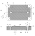
- FIG. 1(a) is a plan view schematically showing an example of the configuration of the heat radiating member 10, and FIG. 1(b) is a cross-sectional view taken along line BB in FIG. 1(a).
- FIG. 1A the outer edge of the metal-silicon carbide composite 20 is indicated by a solid line, and the outer edge of the metal layer 30 is indicated by a dotted line.
- the heat radiating member 10 of FIGS. 1(a) and 1(b) includes a metal-silicon carbide composite 20 formed by impregnating the molten aluminum 3 into the silicon carbide based porous body 2 and solidifying it in the above impregnation step.
- a screw hole 60 is formed in the metal portion 32 filled in the through-hole 40 in the above impregnation step.
- the screw holes 60 are used when the heat dissipation member 10 is joined to another member (for example, a plastic case or the like) with a screw or the like.
- the inner surface of the screw hole 60 is composed of the metal portion 32b containing aluminum.
- Aluminum is a flexible metal material that forms thread grooves more easily than silicon carbide. For this reason, the screw or the like can be fixed in close contact with the metal portion 32a, so that the bonding strength can be increased. Therefore, the screw hole 60 has a structure excellent in easiness of screw tightening. Further, screw hole 60 is formed such that metal portion 32b made of a flexible metal material is covered with a silicon carbide-based porous body. Therefore, the screw hole 60 has a structure with excellent mechanical strength.
- FIG. 2 is a cross-sectional view schematically showing an example of the configuration of the electronic device 100.
- the electronic device 100 of FIG. 2 has a structure in which a screw 64 is inserted into a screw hole 60 and a case 80 is joined to a heat dissipation member 10 .
- a screw 64 can be used to detachably fix another member to the heat radiating member 10 having the screw hole 60 .
- the tapered portions 50 in FIG. 2 are formed around both ends of the through hole 40 and are configured so that the inner diameter of the through hole 40 gradually widens toward the outside.
- the head of the screw 64 is fixed in close contact with the metal portion 32a on the tapered portion 50.
- the hole diameter D2 of the screw hole 60 is made smaller than the maximum hole diameter (hole diameter D1) of the tapered portion 50 .
- the volume ratio of aluminum to silicon carbide in the vicinity of through hole 40 can be reduced. Therefore, it is possible to suppress a decrease in the mechanical strength of metal-silicon carbide composite 20 . Moreover, it is possible to suppress strain caused by the difference in linear expansion coefficient between aluminum and silicon carbide.
- FIG. 5 is a process cross section for explaining the impregnation process when there is a taper forming process.
- FIG. 5 shows an impregnation step of impregnating molten aluminum 3 into silicon carbide porous body 2 (preform) in which through holes 40 are formed.
- silicon carbide porous body 2 sandwiched between spacers 1a and 1b is placed in the space in the mold, and heat-melted aluminum, that is, molten aluminum 3 is supplied.
- the supplied molten aluminum 3 impregnates the inside of the silicon carbide porous body 2.
- the aluminum impregnated inside the silicon carbide porous body 2 and near the surface of the silicon carbide porous body 2 The existing ones are solidified first to become the solidified aluminum 3b.
- the molten aluminum 3 supplied later has its flow path blocked by the solidified aluminum 3b that solidifies first, so that it becomes difficult for the molten aluminum 3 to move through the inside or near the surface of the silicon carbide porous body 2 .
- the through-hole 40 in FIG. 6A is formed by a general method such as drilling, and has a tubular shape having the same hole diameter without a tapered portion in the plate thickness direction of the silicon carbide porous body 2 .
- FIG. 6(a) shows a state in which the flow 3a of the molten aluminum 3 is obstructed by the solidified aluminum 3b that has solidified previously. This is because the molten aluminum 3 cannot move inside the silicon carbide porous body 2 where the solidified aluminum 3b exists, and it becomes difficult for the molten aluminum 3 to pass near the surface around the end of the through-hole 40 . Therefore, the supply amount of the molten aluminum 3 moving to the through hole 40 is insufficient.
- the through-hole 40 of FIG. 5(a) has a tapered portion 50 around both ends in which the inner diameter of the through-hole 40 gradually widens toward the outside.
- the tapered portion 50 of the through-hole 40 serves as a channel that is not blocked by the previously solidified aluminum 3b. Molten aluminum 3 can move around the end of through hole 40 through this channel. Then, the flow 3a of the supplied molten aluminum 3 becomes better than that in FIG. 6(a). Therefore, a sufficient amount of molten aluminum 3 can be supplied into the through hole 40 .
- the molten aluminum 3 in the through-hole 40 is solidified in such a state, it is possible to suppress the generation of voids 4 in the metal portion 32 inside the through-hole 40 as shown in FIG. 5(b).
- FIGS. 3 is a perspective view schematically showing an example of the manufacturing process of the heat radiating member
- FIG. 4 is a cross-sectional view taken along the line AA in FIG. 3(c)
- FIG. 5 is an example of the impregnation process. It is a process sectional view showing typically.
- the flat silicon carbide porous body 2b shown in FIG. 3(a) is manufactured.
- the silicon carbide porous body SiC preform
- SiC preform silicon carbide porous body
- it can be manufactured by a known method.
- it can be produced by adding silica, alumina, or the like as a binder to silicon carbide (SiC) powder as a raw material, mixing, molding, and firing at 800° C. or higher.
- a known method can be appropriately applied.
- a dry press method, a wet press method, an extrusion molding method, an injection method, a casting method, a punching method after sheet molding, and the like can be used.
- a higher SiC content in the silicon carbide-based porous body is preferable because the thermal conductivity is higher and the thermal expansion coefficient is smaller. However, if the content is too high, the aluminum alloy may not be sufficiently impregnated. Practically, a SiC preform containing 40% by mass or more of coarse SiC particles having an average particle diameter of preferably 40 ⁇ m or more and having a relative density in the range of 55% or more and 75% or less is suitable.
- the strength of the silicon carbide-based porous body is preferably 3 MPa or more in terms of bending strength in order to prevent cracking during handling and impregnation.
- the average particle size is obtained by using a scanning electron microscope (eg, "JSM-T200 type” manufactured by JEOL Ltd.) and an image analyzer (eg, manufactured by Nippon Avionics Co., Ltd.), and the average value of the diameters obtained for 1000 particles is calculated. can be measured by Also, the relative density can be measured by the Archimedes method or the like.
- the particle size of the SiC powder which is the raw material of the silicon carbide porous body (SiC preform)
- SiC preform the raw material of the silicon carbide porous body
- a mixed powder obtained by mixing (i) SiC coarse powder having an average particle size of 40 ⁇ m to 150 ⁇ m and (ii) SiC fine powder having an average particle size of 5 ⁇ m to 15 ⁇ m is suitable.
- the ratio of (i) and (ii) in the mixed powder is preferably 40% by mass or more and 80% by mass or less for (i) and 20% by mass or more and 60% by mass or less for (ii).
- a silicon carbide-based porous body is obtained by degreasing, sintering, or the like a molded body of a mixture of SiC powder and a binder.
- the firing temperature is 800° C. or higher, it is easy to obtain a silicon carbide porous body (SiC preform) having a bending strength of 3 MPa or higher regardless of the firing atmosphere.
- firing at a temperature exceeding 1100° C. in an oxidizing atmosphere may accelerate the oxidation of SiC and reduce the thermal conductivity of the metal-silicon carbide composite. Therefore, it is preferable to bake at a temperature of 1100° C. or less in an oxidizing atmosphere.
- the sintering time may be appropriately determined according to conditions such as the size of the silicon carbide porous body (SiC preform), the amount to be charged into the sintering furnace, and the sintering atmosphere.
- SiC preform silicon carbide porous body
- At least one surface of the silicon carbide porous body may be processed by a cutting/grinding tool such as a lathe so as to have an outwardly convex curved shape. Not only one side of the silicon carbide porous body (SiC preform) but also both sides may be processed. In this way, by performing machining (cutting) at the preform stage, there is no need to use special tools for cutting after metal impregnation, and the degree of curvature and flatness can be easily controlled.
- the outer periphery of the silicon carbide porous body 2b is processed to form the silicon carbide porous body 2 of FIG. 3(b) having a desired outer peripheral structure. Specifically, at least four corners of the silicon carbide porous body 2 may be formed with notch portions 22 that are partly excluded.
- through holes 40 are formed in the plate-like silicon carbide porous body 2 so as to penetrate in the plate thickness direction.
- a plurality of through-holes 40 in FIG. 3B are formed in the periphery of the silicon carbide porous body 2 .
- Through-holes 40 can be formed by machining such as drilling.
- a taper portion 50 shown in FIG. 3C is formed at one or both ends of the through hole 40 .
- the hole diameter D1 (taper diameter) of 50 and the height H (taper height) of the taper portion 50 can be controlled.
- the angle ⁇ (taper angle) of the tapered portion 50 can be controlled by the hole diameter D1 and the height H.
- the taper diameter (hole diameter D1) is defined as the maximum diameter of the through hole 40 in the plate thickness direction in one of the cross-sectional views of the heat radiating member 10 in FIG.
- the hole diameter D0 of the through-hole 40 is defined as the minimum diameter of the through-hole 40 in the plate thickness direction in one of the cross-sectional views of the heat radiating member 10 in FIG.
- the taper diameter is, for example, +6 to +40 mm, preferably +8 to +36 mm, and more preferably +10 to +32 mm with respect to the minimum hole diameter (hole diameter D0) of the through hole 40 .
- the taper diameter may be configured such that the pore diameter D1/pore diameter D0 satisfies, for example, 1.5-16, preferably 2-15, more preferably 2.3-14.
- An example of the hole diameter D0 of the through-holes 40 can be appropriately selected according to the area and application of the flat silicon carbide porous body 2. 9 mm.
- auxiliary line L1 may be formed along the main surface of silicon carbide porous body 2 .
- the taper height (height H) is, for example, 0.1 to 1 mm, preferably 0.2 to 0.8 mm, more preferably 0.3 to 0.6 mm.
- the taper angle is defined as the angle ( ⁇ ) formed by the auxiliary line L1 and the auxiliary line L3 drawn along the tapered surface of the tapered portion 50 in one of the cross-sectional views of the heat radiating member 10 in FIG. .
- the taper angle ( ⁇ ) is, for example, 0.2 to 7°, preferably 0.3 to 6°, more preferably 0.4 to 5°.
- the shape of the tapered portion 50 is not particularly limited as long as it serves as a flow path for the molten aluminum 3 .
- the shape of the tapered portion 50 when viewed from the direction perpendicular to the main surface of the silicon carbide porous body 2 (hereinafter referred to as the direction perpendicular to the main surface) is a ring-like shape surrounding the perimeter of the through hole 40. It may have a structure, but is not limited to this.
- the outer edge shape of this tapered portion 50 may be configured to be a circle such as a perfect circle or an ellipse, or a polygon such as a quadrangle or a hexagon.
- the tapered portion 50 may have a plurality of spaced portions that are spaced apart from each other when viewed in the direction perpendicular to the main surface. That is, the tapered portion 50 may have two or more individual flow paths for the molten aluminum 3 . Also, a part of the tapered part 50 when viewed from the direction perpendicular to the main surface may have an extension part that protrudes to the outer edge side more than the other part. The outer edge or extending portion of tapered portion 50 may reach the outer peripheral edge of silicon carbide porous body 2, but from the viewpoint of mechanical strength, it is preferably located inside the outer peripheral edge.
- the tapered surface of the tapered portion 50 in the cross-sectional view of the silicon carbide porous body 2 may be linear or curved, and may have one or more steps or grooves in the surface. Specifically, the tapered surface of FIG. 2 in cross-sectional view of silicon carbide porous body 2 may be linear. As a result, the flow 3a of the molten aluminum 3 is improved.
- the flat silicon carbide porous body 2 is impregnated with a metal containing aluminum to obtain a metal-silicon carbide composite 20 .
- the silicon carbide-based porous body 2 sandwiched between spacers 1a and 1b on both sides is set in a mold, and then molten metal (metal containing aluminum) is introduced into the mold. . Then, by pressing the molten metal, the metal is impregnated into the voids of the silicon carbide porous body 2, and the through holes 40 are filled with the metal.
- molten metal metal containing aluminum
- FIG. 5(b) after cooling, a metal-silicon carbide composite 20 containing aluminum is obtained. At this time, the metal is cooled inside the through-hole 40 to fill the metal portion 32 .
- the spacers 1a and 1b are not particularly limited as long as they can release the obtained metal-silicon carbide composite 20 from the mold.
- a laminated structure of a silicon carbide porous body in which another silicon carbide porous body and another spacer are further arranged on the spacer 1a may be used in the impregnation step.
- the preheating temperature is, for example, 500° C. or higher and 650° C. or lower.
- metal layer 30 is provided on the surface (such as the main surface) of the metal-silicon carbide composite 20.
- metal layer 30 containing aluminum can be formed on one side or both sides of metal-silicon carbide composite 20 .
- a mold for impregnation a mold having dimensions slightly larger than the dimensions of the SiC preform is prepared, the SiC preform is placed in the mold, and the molten metal is injected to obtain the surface metal. Layers can be provided.
- one or more of fibers, spherical particles, and crushed particles made of alumina or silica are placed in direct contact with the surface of the SiC preform, and then impregnated with metal.
- a surface metal layer may be provided.
- the content of the material made of one or more of fibers, spherical particles, and crushed particles made of alumina or silica in the surface metal layer is preferably relative to the mass of the metal-silicon carbide composite. is 0.1% by mass or more and 5% by mass or less, more preferably 0.3% by mass or more and 2% by mass or less.
- the surface metal layer can be formed by placing a metal thin plate or thin film on the surface of the SiC preform and then impregnating the metal, or by adding grooves or the like to the surface of the SiC preform in advance. can be provided.
- the pressing pressure of the molten metal is not particularly limited as long as the metal is sufficiently impregnated, but it is, for example, 30 MPa or more.
- the impregnating metal preferably has a reasonably low melting point.
- an aluminum alloy containing 7% by mass or more and 25% by mass or less of silicon is preferable.
- magnesium by containing 0.2% by mass or more and 5% by mass or less of magnesium, the bonding between the silicon carbide grains and the metal portion becomes stronger, which is preferable.
- Metal components other than aluminum, silicon and magnesium in the aluminum alloy are not particularly limited as long as the properties do not change extremely, and for example copper may be included.
- AC4C As the aluminum alloy, it is also possible to preferably use AC4C, AC4CH, ADC12, etc., which are alloys for casting.
- the metal-silicon carbide composite 20 may be annealed for the purpose of removing strain generated during impregnation.
- the annealing treatment can be performed, for example, at a temperature of about 400° C. or higher and 550° C. or lower for 10 minutes or longer.
- the heat dissipation member 10 of the present embodiment is obtained.
- the manufacturing method of the heat radiating member of this embodiment is not limited to the above.
- the surface metal layer may not necessarily be formed because the surface metal layer has an arbitrary configuration.
- a step of polishing or blasting the surface of the obtained heat radiating member 10 may be performed.
- a step of forming screw holes may be performed after the impregnation step.
- a screw hole is formed in the metal portion 32 formed by filling the inside of the through hole 40 with aluminum.
- the heat dissipating member 10 of FIG. 1(b) includes a screw 64 formed in the metal portion 32b inside the through hole 40. As shown in FIG.
- the screw 64 is a non-through hole and has a thread formed on its inner surface.
- the hole diameter of the screw 64 is D2
- the maximum hole diameter of the through hole 40 is D1.
- D2/D1 is, for example, 0.1 to 0.9, preferably 0.15 to 0.7, more preferably 0.2 to 0.6.
- a plating process may be performed after the impregnation process.
- a plated layer can be provided on the main surface side of the heat dissipation member 10 by a known electroless Ni--P plating or Ni--B plating technique.
- the heat dissipation member 10 may further include a plating layer formed on the surface of the metal portion 32b inside the screw hole 62 of FIG. 1(b).
- the thickness of the metal portion 32b is W1
- the thickness of the plated layer inside the screw hole 62 is W2.
- W2/W1 is, for example, 0.001 to 0.04, preferably 0.002 to 0.03, more preferably 0.003 to 0.02.
- the heat dissipation member 10 of this embodiment will be described in detail.
- the heat dissipation member 10 of FIGS. 1A and 1B includes a flat metal-silicon carbide composite 20 and a metal layer 30 formed on at least both front and back surfaces of the metal-silicon carbide composite 20 .
- main surface 30A the surface on which electronic components are mounted
- back surface 30B the other surface
- main surface 30A and/or back surface 30B (that is, the surface of heat dissipation member 10) can be metal-silicon carbide composite 20 containing aluminum.
- main surface 30A and/or back surface 30B (surface of heat dissipation member 10) may be metal layer 30.
- the main surface 30A and/or the back surface 30B of the heat dissipation member 10 are preferably provided with a metal layer 30 (surface metal layer) containing aluminum.
- the portion of heat radiating member 10 other than the surface metal layer may be a metal-silicon carbide composite or the like.
- the heat dissipating member 10 of FIG. 1A has a plurality of screw holes 62 (through holes) in its peripheral portion. More specifically, when the heat dissipating member 10 is substantially rectangular as described later, screw holes 62 are provided in the metal layer 30a formed in the notch portions 22 at least at the four corners of the heat dissipating member 10. is preferred.
- the screw holes 62 are used when the heat radiating member 10 is joined to other heat radiating components (such as heat radiating fins) with screws or the like.
- the electronic component can be, for example, a power semiconductor element.
- a large amount of heat can be emitted from the electronic element 90, which is a power semiconductor element. The heat can be efficiently exhausted.
- Electronic device 90 includes at least a ceramic substrate 92 .
- the electronic element 90 has a structure in which a ceramic substrate 92 is sandwiched between two metal layers 13 .
- the electronic element 90 is mounted on the main surface 3A side of the heat dissipation member 10 by being soldered with solder 70, for example.
- solder 70 for example.
- the electronic element 90 covers 10 to 80% of the area of the heat dissipation member 10 .
- the heat dissipation member 10 is preferably substantially rectangular. That is, the shape of the heat radiating member 10 is substantially rectangular when viewed from the direction perpendicular to the main surface 30A of the heat radiating member 10 .
- substantially rectangular means that at least one of the four corners of the heat dissipation member 10 may be processed into a rounded shape instead of a right-angled shape (of course, the four corners are right-angled). shape).
- the point where the straight line portions of the short side and the long side when the heat dissipation member 10 is viewed from above are extended is , can be defined as the “vertices” of a rectangle.
- the “length of the short side” and the “length of the long side” of the heat dissipation member 10 can be defined with the “vertex” as the starting point or the ending point.
- the vertical and horizontal lengths of the heat dissipation member 1 are, for example, about 40 mm ⁇ 90 mm to 140 mm ⁇ 250 mm.
- the thickness of the heat radiating member 1 is, for example, 2 mm or more and 6 mm or less, preferably 3 mm or more and 5 mm or less.
- the thickness of the heat radiating member 1 is not uniform, it is preferable that at least the thickness of the center of gravity of the heat radiating member 1 is within the above range.
- the thickness of the heat radiating member 1 is not uniform, it is preferable that the thickness of each portion other than the holes is within the above range.
- the average thermal expansion coefficient of the heat radiating member 10 from 25° C. to 150° C. is, for example, 4 to 12 ppm/K, preferably 4 to 10 ppm/K. As a result, it is possible to suppress cracks, cracks, etc. caused by the difference in coefficient of thermal expansion from the ceramic plate.
- the coefficient of linear thermal expansion the value when the temperature is lowered from 150° C. to 25° C. is used.
- the coefficient of linear thermal expansion can be measured with a thermal dilatometer in accordance with JIS R1618 under the condition that the temperature drop rate is 5° C./min or less.
- the thermal conductivity of the heat radiating member 10 in the plate thickness direction at 25°C is, for example, 150 to 300 W/m ⁇ K, preferably 180 to 300 W/m ⁇ K.
- metal included in metal-silicon carbide composite 20 may be, for example, aluminum, an aluminum alloy, magnesium, or a magnesium alloy. From the viewpoint of thermal conductivity, metal-silicon carbide composite 20 preferably contains aluminum or an aluminum alloy. Also, examples of alloys include aluminum alloys containing 7 to 25% by mass of silicon (Si). By using an aluminum alloy containing 7 to 25% by mass of silicon, the effect of promoting densification of the metal-silicon carbide composite 20 can be obtained.
- the metal-silicon carbide composite 20 is an aluminum-silicon carbide composite, it contains aluminum as a main component, and the content of aluminum in the metal is, for example, 60 to 100% by mass, 80 to 99.8% by mass. % is fine.
- the metal contained in the aluminum-silicon carbide composite contains one or more elements selected from the group consisting of magnesium, silicon, iron and copper, in addition to the main component aluminum, as long as the effects of the present invention are not impaired. may be
- the metal contained in the metal layer 30 may be of the same type as the metal contained in the metal-silicon carbide composite 20, and may be, for example, aluminum, an aluminum alloy, magnesium, or a magnesium alloy.
- the thickness of the metal layer 30 is, for example, 10-300 ⁇ m, preferably 30-150 ⁇ m.
- the film strength of the metal layer 30 can be improved by making it equal to or higher than the above lower limit. By making it equal to or less than the above upper limit, it is possible to suppress the occurrence of warping due to the difference in thermal expansion coefficient from the metal-silicon carbide composite 20 .
- Thermal conductivity can be measured according to JIS R1611 by a laser flash method.
- the material of the ceramic substrate 92 included in the electronic component is not particularly limited as long as it is a ceramic material.
- examples include nitride ceramics such as silicon nitride and aluminum nitride, oxide ceramics such as aluminum oxide and zirconium oxide, carbide ceramics such as silicon carbide, and boride ceramics such as lanthanum boride.
- nitride ceramics such as silicon nitride and aluminum nitride
- oxide ceramics such as aluminum oxide and zirconium oxide
- carbide ceramics such as silicon carbide
- boride ceramics such as lanthanum boride.
- aluminum nitride, silicon nitride, and aluminum oxide are preferable from the viewpoint of insulation, strength of bonding with the metal layer 13, mechanical strength, and the like.
- the brazing material for joining the metal layer 30 and the ceramic substrate 92 an Ag--Cu based brazing material is preferable. That is, the brazing material is preferably a mixture of Ag powder, Cu powder, or the like.
- the brazing material may contain Sn or In for the purpose of improving wettability with the ceramic plate.
- the brazing filler metal preferably contains an active metal from the viewpoint of enhancing reactivity with the ceramic plate. Active metals include titanium, zirconium, hafnium, niobium, and the like. Titanium is preferably contained from the viewpoint of high reactivity with the aluminum nitride substrate or the silicon nitride substrate and the ability to significantly increase the bonding strength.
- solder 70 although the type is not particularly limited, for example, lead-tin eutectic solder or lead-free solder can be used.
- the heat dissipation member 10 may have a plating layer formed on the main surface 30A side of the heat dissipation member 10, specifically on the outermost surface. Thereby, the bondability with solder can be improved.
- the plating layer may contain at least one of Ni, Au and Ag. Among these, the plating layer is preferably composed of a Ni plating layer containing Ni.
- the thickness of the plating layer is, for example, 3-15 ⁇ m, preferably 4-10 ⁇ m. By making it equal to or higher than the above lower limit, the coating stability of the plating layer can be improved. When the thickness is equal to or less than the above upper limit, it is possible to suppress the occurrence of warping due to the difference in thermal expansion coefficient from the underlying layer such as the metal layer 30 .
- the resulting mixture was put into a mold and press-molded at a pressure of 10 MPa. As a result, a flat plate-like compact having dimensions of 135 mm ⁇ 75 mm ⁇ 5.0 mm was obtained.
- the obtained molded body was sintered in the air at a temperature of 900° C. for 2 hours to obtain a silicon carbide porous body having a relative density (bulk density) of 65% by volume.
- Through-holes were formed in the four corners of the silicon carbide porous body using a drill. Subsequently, a tapering tool (tool 5) having a predetermined angle shown in FIG. 4 was pressed against both ends of each through-hole to form a tapered portion.
- the dimensions of the tapered portions of Examples 1 and 2 are shown in Table 1 below. In Comparative Example 1, no tapered portion was formed.
- the hole diameter of the through-holes in Table 1 means the minimum hole diameter (D0).
- the product was cooled to 25° C., and then cut along the shape of the stainless steel plate with a wet band saw to remove the sandwiched stainless steel plate. Further, after that, annealing treatment was performed at a temperature of 500° C. for 3 hours in order to remove distortion during impregnation. As described above, an aluminum-silicon carbide composite was obtained.
- the outer periphery of the obtained aluminum-silicon carbide composite was machined with an NC lathe to obtain a length and width of 140 mm ⁇ 80 mm. Subsequently, a screw hole (hole diameter D2: 4 mm) was formed in the metal portion formed in the through hole of the aluminum-silicon carbide composite. As described above, a heat radiating member without a plating layer was obtained.
Landscapes
- Engineering & Computer Science (AREA)
- Physics & Mathematics (AREA)
- Thermal Sciences (AREA)
- Microelectronics & Electronic Packaging (AREA)
- Cooling Or The Like Of Semiconductors Or Solid State Devices (AREA)
- Chemical & Material Sciences (AREA)
- Materials Engineering (AREA)
Priority Applications (4)
| Application Number | Priority Date | Filing Date | Title |
|---|---|---|---|
| US18/698,607 US20240413051A1 (en) | 2021-10-06 | 2022-10-03 | Heat dissipation member |
| EP22878466.6A EP4411809A4 (en) | 2021-10-06 | 2022-10-03 | Heat dissipation member |
| JP2023552868A JP7689194B2 (ja) | 2021-10-06 | 2022-10-03 | 放熱部材 |
| CN202280066951.1A CN118056273A (zh) | 2021-10-06 | 2022-10-03 | 散热构件 |
Applications Claiming Priority (2)
| Application Number | Priority Date | Filing Date | Title |
|---|---|---|---|
| JP2021164568 | 2021-10-06 | ||
| JP2021-164568 | 2021-10-06 |
Publications (1)
| Publication Number | Publication Date |
|---|---|
| WO2023058597A1 true WO2023058597A1 (ja) | 2023-04-13 |
Family
ID=85804263
Family Applications (1)
| Application Number | Title | Priority Date | Filing Date |
|---|---|---|---|
| PCT/JP2022/036939 Ceased WO2023058597A1 (ja) | 2021-10-06 | 2022-10-03 | 放熱部材 |
Country Status (5)
| Country | Link |
|---|---|
| US (1) | US20240413051A1 (https=) |
| EP (1) | EP4411809A4 (https=) |
| JP (1) | JP7689194B2 (https=) |
| CN (1) | CN118056273A (https=) |
| WO (1) | WO2023058597A1 (https=) |
Cited By (1)
| Publication number | Priority date | Publication date | Assignee | Title |
|---|---|---|---|---|
| JP2023055311A (ja) * | 2021-10-06 | 2023-04-18 | デンカ株式会社 | 放熱部材の製造方法 |
Citations (7)
| Publication number | Priority date | Publication date | Assignee | Title |
|---|---|---|---|---|
| JP2002299532A (ja) | 2001-04-02 | 2002-10-11 | Hitachi Metals Ltd | Al−SiC系複合体および放熱部品 |
| JP2008240155A (ja) * | 2003-05-16 | 2008-10-09 | Hitachi Metals Ltd | 高熱伝導・低熱膨張複合材及び放熱基板 |
| WO2017022012A1 (ja) * | 2015-07-31 | 2017-02-09 | 電気化学工業株式会社 | アルミニウム‐炭化珪素質複合体及びその製造方法 |
| WO2020013300A1 (ja) * | 2018-07-13 | 2020-01-16 | デンカ株式会社 | 金属-炭化珪素質複合体、及び金属-炭化珪素質複合体の製造方法 |
| JP2020012194A (ja) * | 2019-06-12 | 2020-01-23 | デンカ株式会社 | 金属−炭化珪素質複合体及びその製造方法 |
| WO2020110824A1 (ja) * | 2018-11-29 | 2020-06-04 | デンカ株式会社 | 放熱部材 |
| JP2021164568A (ja) | 2020-04-07 | 2021-10-14 | 国立大学法人 岡山大学 | 塞栓物質の作製方法、塞栓物質および塞栓物質作製用キット |
Family Cites Families (21)
| Publication number | Priority date | Publication date | Assignee | Title |
|---|---|---|---|---|
| JPH07161925A (ja) * | 1993-12-09 | 1995-06-23 | Mitsubishi Electric Corp | パワーモジュール |
| JP2000082774A (ja) * | 1998-06-30 | 2000-03-21 | Sumitomo Electric Ind Ltd | パワ―モジュ―ル用基板およびその基板を用いたパワ―モジュ―ル |
| US6188579B1 (en) * | 1999-07-12 | 2001-02-13 | Lucent Technologies Inc. | Apparatus and methods for forming a printed wiring board assembly to reduce pallet warpage |
| US6222264B1 (en) * | 1999-10-15 | 2001-04-24 | Dell Usa, L.P. | Cooling apparatus for an electronic package |
| US7019975B2 (en) * | 2000-08-09 | 2006-03-28 | Mitsubishi Materials Corporation | Power module and power module with heat sink |
| JPWO2005088711A1 (ja) * | 2004-03-16 | 2008-01-31 | 松下電器産業株式会社 | ドライバモジュール構造 |
| EP1858078A4 (en) * | 2005-01-20 | 2009-03-04 | Almt Corp | ELEMENT FOR A SEMICONDUCTOR COMPONENT AND MANUFACTURING METHOD THEREFOR |
| EP1973157B1 (en) * | 2006-01-13 | 2017-06-21 | Denka Company Limited | Aluminum/silicon carbide composite and heat dissipation device employing the same |
| US8525214B2 (en) * | 2008-03-25 | 2013-09-03 | Bridge Semiconductor Corporation | Semiconductor chip assembly with post/base heat spreader with thermal via |
| US7837353B2 (en) * | 2008-08-28 | 2010-11-23 | Fu Zhun Precision Industry (Shen Zhen) Co., Ltd. | LED assembly preventing electrostatic accumulation thereon |
| US7837354B2 (en) * | 2008-09-01 | 2010-11-23 | Fu Zhun Precision Industry (Shen Zhen) Co., Ltd. | Method for mounting an LED module on a support |
| US8237260B2 (en) * | 2008-11-26 | 2012-08-07 | Infineon Technologies Ag | Power semiconductor module with segmented base plate |
| CN102834534B (zh) * | 2010-04-02 | 2014-07-30 | 住友电气工业株式会社 | 镁基复合构件、散热构件和半导体装置 |
| US8279608B2 (en) * | 2010-08-31 | 2012-10-02 | Chen chuan-fu | Heatsink device directly contacting a heat source to achieve a quick dissipation effect |
| JP2012254891A (ja) * | 2011-06-08 | 2012-12-27 | Denki Kagaku Kogyo Kk | アルミニウム−炭化珪素質複合体とその製造方法 |
| JP6035015B2 (ja) * | 2011-09-09 | 2016-11-30 | ソニー株式会社 | 回路基板 |
| WO2014057769A1 (ja) * | 2012-10-12 | 2014-04-17 | 新東工業株式会社 | 減圧治具及び減圧治具を用いた被加圧物の加圧方法 |
| WO2016002943A1 (ja) * | 2014-07-04 | 2016-01-07 | 電気化学工業株式会社 | 放熱部品及びその製造方法 |
| DE112014006796B4 (de) * | 2014-07-09 | 2023-12-28 | Mitsubishi Electric Corporation | Halbleiteranordnung |
| CN106952875A (zh) * | 2017-02-27 | 2017-07-14 | 扬州国扬电子有限公司 | 一种AlSiC底板及其安装孔防裂的方法 |
| CN116711072A (zh) * | 2021-01-22 | 2023-09-05 | 三菱电机株式会社 | 半导体装置及半导体装置的制造方法 |
-
2022
- 2022-10-03 WO PCT/JP2022/036939 patent/WO2023058597A1/ja not_active Ceased
- 2022-10-03 EP EP22878466.6A patent/EP4411809A4/en not_active Withdrawn
- 2022-10-03 CN CN202280066951.1A patent/CN118056273A/zh active Pending
- 2022-10-03 US US18/698,607 patent/US20240413051A1/en active Pending
- 2022-10-03 JP JP2023552868A patent/JP7689194B2/ja active Active
Patent Citations (7)
| Publication number | Priority date | Publication date | Assignee | Title |
|---|---|---|---|---|
| JP2002299532A (ja) | 2001-04-02 | 2002-10-11 | Hitachi Metals Ltd | Al−SiC系複合体および放熱部品 |
| JP2008240155A (ja) * | 2003-05-16 | 2008-10-09 | Hitachi Metals Ltd | 高熱伝導・低熱膨張複合材及び放熱基板 |
| WO2017022012A1 (ja) * | 2015-07-31 | 2017-02-09 | 電気化学工業株式会社 | アルミニウム‐炭化珪素質複合体及びその製造方法 |
| WO2020013300A1 (ja) * | 2018-07-13 | 2020-01-16 | デンカ株式会社 | 金属-炭化珪素質複合体、及び金属-炭化珪素質複合体の製造方法 |
| WO2020110824A1 (ja) * | 2018-11-29 | 2020-06-04 | デンカ株式会社 | 放熱部材 |
| JP2020012194A (ja) * | 2019-06-12 | 2020-01-23 | デンカ株式会社 | 金属−炭化珪素質複合体及びその製造方法 |
| JP2021164568A (ja) | 2020-04-07 | 2021-10-14 | 国立大学法人 岡山大学 | 塞栓物質の作製方法、塞栓物質および塞栓物質作製用キット |
Non-Patent Citations (1)
| Title |
|---|
| See also references of EP4411809A4 |
Cited By (2)
| Publication number | Priority date | Publication date | Assignee | Title |
|---|---|---|---|---|
| JP2023055311A (ja) * | 2021-10-06 | 2023-04-18 | デンカ株式会社 | 放熱部材の製造方法 |
| JP7733530B2 (ja) | 2021-10-06 | 2025-09-03 | デンカ株式会社 | 放熱部材の製造方法 |
Also Published As
| Publication number | Publication date |
|---|---|
| JPWO2023058597A1 (https=) | 2023-04-13 |
| EP4411809A1 (en) | 2024-08-07 |
| US20240413051A1 (en) | 2024-12-12 |
| JP7689194B2 (ja) | 2025-06-05 |
| CN118056273A (zh) | 2024-05-17 |
| EP4411809A4 (en) | 2025-02-19 |
Similar Documents
| Publication | Publication Date | Title |
|---|---|---|
| JP4761157B2 (ja) | アルミニウム−炭化珪素質複合体 | |
| JP5021636B2 (ja) | アルミニウム−炭化珪素質複合体及びその加工方法 | |
| EP1973157A1 (en) | Aluminum/silicon carbide composite and heat radiation part making use of the same | |
| JP7427647B2 (ja) | 放熱部材 | |
| JP7116689B2 (ja) | 放熱部材およびその製造方法 | |
| CN106796925B (zh) | 铝-碳化硅质复合体及其制造方法 | |
| JP3907620B2 (ja) | セラミックス回路基板一体型アルミニウム−炭化珪素質複合体及びその製造方法 | |
| WO2023058597A1 (ja) | 放熱部材 | |
| JP7596363B2 (ja) | 素子搭載基板、および素子搭載基板の製造方法 | |
| JP6591113B1 (ja) | 放熱部材およびその製造方法 | |
| JP2023055311A (ja) | 放熱部材の製造方法 | |
| JP4191124B2 (ja) | アルミニウム合金−セラミックス質複合体及びその製造方法 | |
| US20240404913A1 (en) | Heat dissipation member | |
| JP3732193B2 (ja) | アルミニウム−炭化珪素質複合体及びその製造方法 | |
| JP4357380B2 (ja) | アルミニウム合金−炭化珪素質複合体の製造方法 | |
| JP2012171838A (ja) | アルミニウム−炭化珪素質複合体の製造方法 | |
| WO2024181224A1 (ja) | セラミックス板、包装体、セラミックス板の製造方法、モジュールおよび電気・電子製品 |
Legal Events
| Date | Code | Title | Description |
|---|---|---|---|
| 121 | Ep: the epo has been informed by wipo that ep was designated in this application |
Ref document number: 22878466 Country of ref document: EP Kind code of ref document: A1 |
|
| ENP | Entry into the national phase |
Ref document number: 2023552868 Country of ref document: JP Kind code of ref document: A |
|
| WWE | Wipo information: entry into national phase |
Ref document number: 202280066951.1 Country of ref document: CN |
|
| WWE | Wipo information: entry into national phase |
Ref document number: 18698607 Country of ref document: US |
|
| WWE | Wipo information: entry into national phase |
Ref document number: 2022878466 Country of ref document: EP |
|
| NENP | Non-entry into the national phase |
Ref country code: DE |
|
| ENP | Entry into the national phase |
Ref document number: 2022878466 Country of ref document: EP Effective date: 20240502 |
|
| WWW | Wipo information: withdrawn in national office |
Ref document number: 2022878466 Country of ref document: EP |