WO2023058589A1 - 切削工具、及び切削加工物の製造方法 - Google Patents
切削工具、及び切削加工物の製造方法 Download PDFInfo
- Publication number
- WO2023058589A1 WO2023058589A1 PCT/JP2022/036898 JP2022036898W WO2023058589A1 WO 2023058589 A1 WO2023058589 A1 WO 2023058589A1 JP 2022036898 W JP2022036898 W JP 2022036898W WO 2023058589 A1 WO2023058589 A1 WO 2023058589A1
- Authority
- WO
- WIPO (PCT)
- Prior art keywords
- hole
- clamper
- cutting tool
- central axis
- insert
- Prior art date
Links
- 238000005520 cutting process Methods 0.000 title claims abstract description 67
- 238000004519 manufacturing process Methods 0.000 title description 10
- 230000000452 restraining effect Effects 0.000 claims abstract description 3
- 239000000463 material Substances 0.000 claims description 27
- 238000000034 method Methods 0.000 description 7
- 229910000831 Steel Inorganic materials 0.000 description 6
- 239000010959 steel Substances 0.000 description 6
- MTPVUVINMAGMJL-UHFFFAOYSA-N trimethyl(1,1,2,2,2-pentafluoroethyl)silane Chemical compound C[Si](C)(C)C(F)(F)C(F)(F)F MTPVUVINMAGMJL-UHFFFAOYSA-N 0.000 description 5
- 229910001018 Cast iron Inorganic materials 0.000 description 4
- 229910052751 metal Inorganic materials 0.000 description 4
- 239000002184 metal Substances 0.000 description 4
- 239000011195 cermet Substances 0.000 description 3
- 230000007423 decrease Effects 0.000 description 3
- 238000010586 diagram Methods 0.000 description 3
- 239000000203 mixture Substances 0.000 description 3
- NRTOMJZYCJJWKI-UHFFFAOYSA-N Titanium nitride Chemical compound [Ti]#N NRTOMJZYCJJWKI-UHFFFAOYSA-N 0.000 description 2
- 230000001154 acute effect Effects 0.000 description 2
- 238000005229 chemical vapour deposition Methods 0.000 description 2
- 239000011248 coating agent Substances 0.000 description 2
- 238000000576 coating method Methods 0.000 description 2
- 238000003754 machining Methods 0.000 description 2
- 238000005240 physical vapour deposition Methods 0.000 description 2
- 229910018072 Al 2 O 3 Inorganic materials 0.000 description 1
- 229910000851 Alloy steel Inorganic materials 0.000 description 1
- 229910000975 Carbon steel Inorganic materials 0.000 description 1
- 229910000760 Hardened steel Inorganic materials 0.000 description 1
- RTAQQCXQSZGOHL-UHFFFAOYSA-N Titanium Chemical compound [Ti] RTAQQCXQSZGOHL-UHFFFAOYSA-N 0.000 description 1
- PNEYBMLMFCGWSK-UHFFFAOYSA-N aluminium oxide Inorganic materials [O-2].[O-2].[O-2].[Al+3].[Al+3] PNEYBMLMFCGWSK-UHFFFAOYSA-N 0.000 description 1
- 239000011230 binding agent Substances 0.000 description 1
- 239000010962 carbon steel Substances 0.000 description 1
- 239000000919 ceramic Substances 0.000 description 1
- 239000002131 composite material Substances 0.000 description 1
- 239000000470 constituent Substances 0.000 description 1
- 239000002173 cutting fluid Substances 0.000 description 1
- -1 ferrous metals Chemical class 0.000 description 1
- 150000002739 metals Chemical class 0.000 description 1
- 238000003801 milling Methods 0.000 description 1
- 239000002245 particle Substances 0.000 description 1
- 230000000149 penetrating effect Effects 0.000 description 1
- 230000002093 peripheral effect Effects 0.000 description 1
- 238000003825 pressing Methods 0.000 description 1
- 239000010935 stainless steel Substances 0.000 description 1
- 229910001220 stainless steel Inorganic materials 0.000 description 1
- 239000010936 titanium Substances 0.000 description 1
- 229910052719 titanium Inorganic materials 0.000 description 1
- 150000003609 titanium compounds Chemical class 0.000 description 1
Images


Classifications
-
- B—PERFORMING OPERATIONS; TRANSPORTING
- B23—MACHINE TOOLS; METAL-WORKING NOT OTHERWISE PROVIDED FOR
- B23B—TURNING; BORING
- B23B27/00—Tools for turning or boring machines; Tools of a similar kind in general; Accessories therefor
- B23B27/14—Cutting tools of which the bits or tips or cutting inserts are of special material
- B23B27/16—Cutting tools of which the bits or tips or cutting inserts are of special material with exchangeable cutting bits or cutting inserts, e.g. able to be clamped
Definitions
- the present disclosure relates to a cutting tool used when cutting a work material such as metal, and a method for manufacturing a cut product.
- the cutting tools described in Patent Documents 1 and 2 are known as cutting tools used for cutting work materials such as metals.
- the cutting tool described in Patent Document 1 has a holder main body, a cutting insert (hereinafter simply referred to as insert), a clamping member and a locking member.
- the clamp member and the lock member in Patent Document 1 each have an abutment surface, and the insert is constrained by sliding the clamp member when these abutment surfaces come into contact with each other.
- the cutting tool described in Patent Document 2 has a tool head, an insert, a screw, and a clamp. In U.S. Pat. No. 5,400,000, the insert is constrained by sliding clamps when the screws are installed.
- a non-limiting example cutting tool in the present disclosure has a rod-shaped holder extending along the central axis from the front end to the rear end, an insert, a clamper, and a screw.
- the holder has a tip surface located on the tip side and a bottom surface parallel to the central axis, and a pocket located on the tip side and extending from the bottom surface in a direction intersecting the central axis. It has a first hole and a second hole that extends from the tip surface toward the rear end and is connected to the first hole.
- An insert is located in the pocket.
- a clamper is capable of restraining the insert and has a through hole inserted into the first hole and opening toward the second hole.
- a screw is inserted into the second hole and the through hole.
- the through hole has a first tapered surface located at an opening toward the second hole, and the screw has a second tapered surface that contacts the first tapered surface.
- FIG. 1 is a perspective view of a cutting tool in a non-limiting embodiment of the present disclosure
- FIG. It is the enlarged view which expanded area
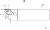
- It is the front view which looked at the cutting tool shown in FIG. 1 from the tip side.
- It is the side view which looked at the cutting tool shown in FIG. 3 from B1 direction.
- It is the top view which looked at the cutting tool shown in FIG. 3 from B2 direction.
- FIG. 5 is a cross-sectional view taken along line VII-VII of FIG. 4
- 8 is an enlarged view of an area A2 shown in FIG. 7;
- FIG. 5 is a cross-sectional view taken along line VII-VII of FIG. 4;
- 8 is an enlarged view of an area A2 shown in FIG. 7;
- FIG. 5 is a cross-sectional view taken along line VII
- FIG. 1 is a schematic diagram illustrating one step in a method for manufacturing a machined workpiece in one non-limiting example
- FIG. 1 is a schematic diagram illustrating one step in a method for manufacturing a machined workpiece in one non-limiting example
- FIG. 1 is a schematic diagram illustrating one step in a method for manufacturing a machined workpiece in one non-limiting example
- FIG. 1 is a schematic diagram illustrating one step in a method for manufacturing a machined workpiece in one non-limiting example
- Cutting tools include, for example, turning tools and milling tools.
- Turning tools include, for example, grooving tools and parting off tools.
- the grooving tool can be used, for example, for grooving.
- the cutting tool 100 in one non-limiting example shown in FIG. 1 is a turning tool, and more specifically a grooving tool.
- the cutting tool 100 may comprise optional components not shown in the referenced figures.
- the dimensions of the members in each drawing do not necessarily represent the actual dimensions of the constituent members, the dimensional ratios of the respective members, and the like faithfully.
- the X-axis direction is the horizontal direction
- the Z-axis direction is the vertical direction
- the Y-axis direction is the front-back direction.
- the side where the insert 2 is positioned is the right side in the X-axis direction, the front side in the Y-axis direction, and the upper side in the Z-axis direction.
- a non-limiting example cutting tool 100 shown in FIGS. 1-8 includes a holder 1, an insert 2, a clamper 3, and a screw 4.
- the holder 1 may have a rod shape extending from the first end 1a toward the second end 1b along the first central axis L1. As shown in FIG. 1, the holder 1 may have a square prism shape.
- the first end 1a is also called “front end 1a”
- the second end 1b is also called “rear end 1b”.
- the front end 1a of the holder 1 in the Y-axis direction may be the front end 1a
- the rear end 1b may be the rear end 1b.
- the size of the holder 1 is not particularly limited.
- the length in the direction along the first central axis L1 can be set to approximately 5 mm to 100 mm.
- the height from the top end to the bottom end, in other words, the width in the vertical direction can be set to about 5 mm to 50 mm.
- Steel, cast iron, or the like may be used as the member of the holder 1 .
- the toughness of the holder 1 is high.
- the holder 1 may have a head 17 and a shank 18.
- the head 17 may be positioned on the tip 1a side of the holder 1 .
- the head 17 may include an end face on the side of the tip 1a, as shown in FIG.
- the shank 18 may be located closer to the rear end 1b than the head 17.
- the shank 18 may include an end face on the rear end 1b side, as shown in FIG.
- the shank 18 may be located closer to the rear end 1b than the head 17, and may include the central portion of the holder 1 in the direction along the first central axis L1, as shown in FIG.
- the shank 18 may be a part that is gripped by the machine tool when the cutting tool 100 is attached to the machine tool.
- the head 17 is a part for gripping the insert 2 and has a pocket 12 which will be described later.
- the shank 18 is generally a simple cylindrical or prismatic shape if it is a part that can be gripped by a machine tool. Therefore, the central axis of the shank 18 may be regarded as the first central axis L1 of the holder 1. As shown in FIG.
- the head 17 of the holder 1 may have a tip surface 11 , a pocket 12 , a first hole 13 and a second hole 14 .
- the tip surface 11 may be located on the tip 1a side of the head 17.
- the tip surface 11 is not limited to a configuration orthogonal to the first central axis L1.
- the distal end surface 11 may be configured to be inclined with respect to the first central axis L1.
- the tip surface 11 need not be formed by one plane.
- the distal end surface 11 may be formed by a plurality of flat surfaces, or may be formed by curved surfaces.
- the pocket 12 may be located on the tip 1a side of the head 17.
- the pocket 12 may be continuous with the tip surface 11 or may extend from the tip surface 11 toward the rear end 1b.
- An insert 2 can be attached to the pocket 12 .
- the pocket 12 is formed by cutting out the tip 1a side portion of the right side surface of the head 17.
- the pocket 12 has a bottom surface 121 parallel to the first central axis L1 and a bottom surface 121 perpendicular to the bottom surface 121. and a constraining side 122 that constrains the lower side 22 of the 2. Parallel here does not need to be exact.
- the bottom surface 121 may have a certain angle such as 5° with respect to the first central axis L1.
- the bottom surface 121 may be a surface on which the insert 2 abuts in the pocket 12 , or the insert 2 may be fixed to the pocket 12 by holding the insert 2 between the bottom surface 121 and the clamper 3 .
- the first hole 13 may extend from the bottom surface 121 at a constant angle with respect to the first central axis L1 of the holder 1 .
- "Forming a certain angle with respect to the first central axis L1" means that the second central axis L2 of the first hole 13 is not parallel to the first central axis L1 of the holder 1.
- the second central axis L2 may be orthogonal to the first central axis L1.
- the first hole 13 may penetrate the head 17 in the X-axis direction, or may have a bottom without penetrating the head 17 .
- the second hole 14 may extend from the tip surface 11 toward the rear end 1b. In the example shown in FIG. 7, the second hole 14 reaches the first hole 13 from the tip surface 11 and further extends from the first hole 13 toward the rear end 1b.
- a thread groove 15 is provided in a portion further extending from the first hole 13 toward the rear end 1b.
- the thread groove 15 is provided concentrically with the third central axis L3 of the second hole 14 .
- the third central axis L3 of the second hole 14 may have a certain angle with respect to the first central axis L1 of the holder 1, or may extend in parallel. When the third central axis L3 of the second hole 14 extends parallel to the first central axis L1 of the holder 1, the insert 2 can be replaced more easily.
- the second hole 14 may be perpendicular to the first hole 13 or may intersect at an acute angle. That is, the third central axis L3 of the second hole 14 may be orthogonal to the second central axis L2 of the first hole 13, or may intersect at an acute angle.
- the insert 2 located in the pocket 12 is not limited to any particular shape.
- the insert 2 may be square plate-shaped.
- the insert 2 is square plate-shaped, for example, the upper side surface 21, the lower side surface 22, the pair of lateral side surfaces 23, the first through hole 24, the notch portion 25, the front side surface 26, the rear side surface 27, and the cutting edge 28 are formed. may have.
- the upper surface 21 may be a surface of the insert 2 located above.
- the lower surface 22 may be the lower lying surface of the insert 2 .
- the pair of lateral sides 23 may be surfaces located between the upper side 21 and the lower side 22 . Assuming that the right side of the pair of lateral sides 23 is the right side 23a and the left side of the pair of lateral sides 23 is the left side 23b, the left side 23b contacts the bottom surface 121. As shown in FIG.
- the upper side surface 21, the lower side surface 22, and the pair of lateral side surfaces 23 may each extend in a direction along the first central axis L1.
- the front side surface 26 is a surface located on the tip 1a side of the insert 2, and may protrude forward from the tip 1a of the cutting tool 100.
- the rear side surface 27 is a surface located on the rear end 1b side of the insert 2 .
- the first through holes 24 may be opened on each of the pair of lateral side surfaces 23 .
- the first through hole 24 may extend from the right side 23a to the left side 23b.
- the first through holes 24 may be opened at the central portions of the pair of lateral side surfaces 23 .
- the clamper 3 is inserted into the first through hole 24 .
- the notch 25 may be formed in the right side 23a so as to be dug toward the left side 23b.
- the notch 25 is connected to the first through hole 24 and is formed to extend from the edge of the first through hole 24 on the rear end 1b side toward the rear end 1b.
- the notch portion 25 has a rectangular hole shape along the shape of the convex portion 32 .
- the first notch 25 may be separated from the first through hole 24 without being connected to the first through hole 24 .
- the insert 2 may be point symmetric with respect to the fourth central axis L4 of the first through hole 24.
- the upper surface 21 has a shape that matches the lower surface 22.
- the cutting edge 28 may be located at the intersection of the upper surface 21 and the front surface 26. Cutting can be performed by bringing this cutting edge 28 into contact with the material to be cut.
- the cutting edge 28 may be located at the intersection of the lower surface 22 and the rear surface 27 in addition to the locations described above.
- the insert 2 is called a two-corner type, which is economical.
- the size of the insert 2 is not particularly limited.
- the length in the direction along the first central axis L1 can be set to approximately 10 mm to 30 mm.
- the height from the upper side surface 21 to the lower side surface 22, in other words, the width in the vertical direction can be set to 5 mm to 15 mm.
- the width between the pair of lateral side surfaces 23 can be set to approximately 2 mm to 10 mm.
- Cemented carbide compositions may include, for example, WC--Co, WC--TiC--Co, and WC--TiC--TaC--Co.
- WC, TiC and TaC may be hard particles and Co may be the binder phase.
- the cermet may be a sintered composite material in which a metal is combined with a ceramic component.
- An example of a cermet may be a titanium compound based on titanium carbide (TiC) or titanium nitride (TiN).
- the material of the insert 2 is not limited to the above composition.
- the surface of the insert 2 may be coated with a coating formed using chemical vapor deposition (CVD) or physical vapor deposition (PVD) methods.
- the composition of the coating may include titanium carbide (TiC), titanium nitride (TiN), titanium carbonitride (TiCN), alumina (Al 2 O 3 ), and the like.
- the clamper 3 may be inserted into a first hole 13 provided in the holder 1 .
- a clamper 3 can constrain the insert 2 and may be used to fix the position of the insert 2 relative to the holder 1 .
- the position of the insert 2 may be fixed by applying a force from the clamper 3 to the insert 2 to press it toward the bottom surface 121 of the pocket 12 .
- the position of the insert 2 may be fixed while the clamper 3 is inserted into the first through hole 24 .
- a portion of the clamper 3 may be brought into contact with the vicinity of the opening of the first through hole 24 on the right side surface 23 a and the other portion of the clamper 3 may be inserted into the first through hole 24 .
- the other portion of the clamper 3 inserted into the first through hole 24 may be inserted into the first hole 13.
- the other portion of the clamper 3 inserted into the first through hole 24 is called a first portion.
- the first portion is drawn into the first hole 13 by tightening the screw 4 , which will be described later, so that the clamper 3 can apply a pressing force to the insert 2 toward the bottom surface 121 of the pocket 12 .
- the fixing of the insert 2 by the clamper 3 is not limited to the above configuration.
- the location where the clamper 3 abuts on the insert 2 is not limited to the vicinity of the opening of the first through hole 24 on the right side surface 23a.
- the portion of the insert 2 with which the clamper 3 abuts may be in the vicinity of the outer peripheral edge of the right side surface 23a.
- the clamper 3 is in contact with the right side surface 23a, and the upper side surface 21, the lower side surface 22, the front side surface 26, or the rear side surface 27 of the insert 2. may be inserted into the first hole 13 so as to wrap around the surface of the .
- the clamper 3 may contact the insert 2 on the rear end 1b side of the first hole 13 .
- the clamper 3 may contact a region of the right side surface 23 a that is closer to the rear end 1 b than the first hole 13 . In this case, the insert 2 is pulled toward the rear end 1b, and the binding force of the insert 2 can be increased.
- the clamper 3 may have a second through hole 33.
- the second through hole 33 may be provided in a portion of the clamper 3 that is inserted into the first hole 13 .
- the second through hole 33 may be opened so as to face the second hole 14 while the clamper 3 is inserted into the first hole 13 . That is, the second through hole 33 and the second hole 14 constitute one hole into which the screw 4 described below is inserted.
- the second through hole 33 has a circular shape larger than the outer diameter of the body of the screw 4, and the clamper 3 is just inserted into the first hole 13. In other words, the screw This is the state before tightening 4.
- the fifth center axis L5 of the second through-hole 33 is positioned closer to the opening of the first hole 13 than the third center axis L3 of the second hole 14 is.
- the second through-hole 33 may have a first tapered surface 34 positioned at the opening toward the second hole 14 .
- the second through hole 33 has a first tapered surface 34 as a portion whose inner diameter gradually decreases from the opening of the second through hole 33 toward the central portion of the second through hole 33. have.
- the second through-hole 33 does not necessarily have to be circular, and may be elongated in the X-axis direction.
- the arc-shaped portion of the second through-hole 33 on the side opposite to the opening of the first hole 13 is provided with a It is only necessary to have a portion (first tapered surface) where the inner diameter of the arc gradually decreases.
- the clamper 3 is not limited to a specific shape, it may be configured to slide in the extending direction of the second central axis L2 of the first hole 13 and not slide around the second central axis L2 of the first hole 13. With such a configuration, the direction of the opening of the second through hole 33 of the clamper 3 can be easily aligned with the second hole 14 of the holder 1 . Therefore, it is easy to insert the screw 4 into the second hole 14 and the second through hole 33, and the replacement work of the insert 2 becomes easier.
- the clamper 3 may be L-shaped with two sides. Let one of the two sides be the first side and the other be the second side.
- the clamper 3 is the first side, and includes the shaft portion 31 as the above-described first portion, the convex portion 32 projecting from the end portion of the shaft portion 31 as the second side, and the second through hole 33 described above. and have The second through-hole 33 is located near the tip of the shaft portion 31 and passes through the shaft portion 31 .
- the diameter of the second through hole 33 is smaller than the diameter of the first hole 13 .
- the convex portion 32 may have a shape in which, for example, a small rectangle and a large rectangle are connected when viewed from the side.
- the protrusion 32 may abut against the right side surface 23a of the insert 2 .
- the large rectangular portion of the projection 32 may be fitted into the cutout portion 25 so as to come into contact with the right side surface 23 a.
- the shaft portion 31 is inserted into the first through hole 24 and the first hole 13 . In this case, since the contact area between the insert 2 and the clamper 3 can be increased, the insert 2 can be firmly fixed by the clamper 3 .
- each shape is non-circular. It is good also as a structure which is a shape. Even with such a configuration, it is difficult for the clamper 3 to slide, in other words, rotate around the second central axis L2.
- the non-circular shape includes, for example, a flattened circular shape such as an elliptical shape, or a polygonal shape.
- the first portion in this cross section may have an elongated shape in the direction orthogonal to the central axis of the holder 1.
- the clamper 3 has the shaft portion 31 .
- the portion of the clamper 3 that is inserted into the first hole 13 has a second cutout portion 35 extending parallel to the second central axis L2, and the first hole 13 is the second cutout portion.
- a protrusion 16 corresponding to the notch 35 may be provided. Even in such a case, the clamper 3 is less likely to rotate around the second central axis L2.
- the material of the clamper 3 for example, steel, cast iron, etc. may be used. In particular, when steel is used among these members, the clamper 3 has high toughness.
- the screw 4 may be inserted into the second hole 14 and the second through hole 33 .
- the screw 4 may have a thread 42 screwed into the second hole 14 and a second tapered surface 41 .
- the screw 4 may have a second tapered surface 41 as a portion whose outer diameter decreases from the head toward the tip.
- the second tapered surface 41 may include up to the tip of the screw 4 or may be provided at a portion away from the tip of the screw 4 .
- the second tapered surface 41 of the screw 4 comes into contact with the first tapered surface 34 positioned at the opening of the second through hole 33 of the clamper 3 .
- the fifth central axis L5 of the second through-hole 33 is located closer to the opening of the first hole 13 than the third central axis L3 of the second hole 14, so that it is shown in FIG. , the second tapered surface 41 may contact the first tapered surface 34 only on the side opposite to the opening side of the first hole 13 .
- the clamper 3 firmly fixes the position of the insert 2 with respect to the holder 1 . Then, the screw 4 can be easily loosened from the opening of the second hole 14 located on the side of the tip 1a to release the restraint of the insert 2 by the clamper 3, and the insert 2 can be replaced. For example, when machining is performed by arranging a plurality of cutting tools 100 on a comb blade turret, the distance between the heads 17 is narrow and it is difficult to rotate the side lock member. The clamper 3 can be unlocked by easily loosening the screw 4 from the front side.
- the screw groove 15 may be formed in a portion closer to the opening of the second hole 14 than the second through hole 33, and may be formed further from the opening of the second hole 14 than the second through hole 33 as described above. It may be formed in parts.
- the thread 42 may be located closer to the tip 1a than the second tapered surface 41, and may be located closer to the rear end 1b than the second tapered surface 41.
- the screw 4 is less likely to loosen.
- the outer diameter of the second tapered surface 41 may be larger than the outer diameter of the screw thread 42 .
- the area of the second tapered surface 41 can be increased, and the contact area between the screw 4 and the clamper 3 can be increased. Therefore, the screws 4 are less likely to loosen.
- the first hole 13 extends from the bottom surface 121 toward the first central axis L1 of the holder 1, and the second hole 14 extends from the front end surface 11 of the holder 1 toward the rear end 1b.
- the clamper 3 When extended, the clamper 3 can be firmly fixed. Then, the screw 4 can be easily loosened and the insert 2 can be replaced.
- the direction in which the insert 2 is clamped is the direction in which the first hole 13 extends
- the direction in which the first hole 13 extends and the direction in which the second hole 14 extends are not parallel to each other, but cross each other. Looseness of 4 is less likely to occur.
- the second hole 14 extends from the tip surface 11 of the holder 1 toward the rear end 1b, so that the operator can easily see the screw 4 and easily turn the screw 4 when replacing the insert 2. Easy.
- steel, cast iron, or the like may be used as the material of the screw 4.
- the toughness of the screw 4 is high.
- a workpiece 101 is produced by cutting a workpiece 103 .
- the manufacturing method of the cut workpiece 101 in the embodiment includes the following steps. Namely (1) a step of rotating the work material 103; (2) A step of contacting the rotating work material 103 with the cutting tool 100 represented by the above embodiment; (3) separating the cutting tool 100 from the work material 103; Prepare.
- the work piece 103 may be rotated around the sixth central axis L6, and the cutting tool 100 may be brought relatively closer to the work piece 103.
- the cutting tool 100 may be brought into contact with the work material 103 to cut the work material 103 .
- the cutting tool 100 may be kept away from the workpiece 103 or the workpiece 101 to be cut.
- the cutting tool 100 is moved in the forward direction of the Y-axis while at least part of the portion of the insert 2 used as the cutting edge 28 is in contact with the rotating work 103.
- the work material 103 may be cut.
- the cutting tool 100 may be moved away from the work material 103 by moving the cutting tool 100 in the rearward direction of the Y-axis while the work material 103 is being rotated.
- the cutting tool 100 is brought into contact with the work material 103 or separated from the work material 103 by moving the cutting tool 100, but the present invention is not limited to this case.
- step (1) the work material 103 may be brought closer to the cutting tool 100 .
- step (3) the work material 103 may be kept away from the cutting tool 100 .
- the process of keeping the workpiece 103 rotated and bringing at least part of the cutting edge 28 of the insert 2 into contact with a different portion of the workpiece 103 may be repeated. .
- Representative examples of the material of the work material 103 include hardened steel, carbon steel, alloy steel, stainless steel, cast iron, non-ferrous metals, and the like.
- the insert 2 since the insert 2 is well fixed to the holder 1 by the cutting tool 100 of the present disclosure, machining can be performed with high accuracy.
- the screw 4 can be easily loosened from the front of the holder 1 to unlock the clamper 3, resulting in good working efficiency.
Abstract
クランパーを介してインサートをホルダに強固に固定することを可能とし、且つ、ネジを容易に緩めてインサートを交換することを可能とする。本開示における限定されない一例の切削工具は、ホルダ、インサート、クランパー、及びネジを有する。ホルダは、先端面、ポケット、第1穴、及び第2穴を有する。インサートは、ポケットに位置する。クランパーは、インサートを拘束可能であって、第1穴に挿入され、且つ、第2穴に向かって開口する貫通孔を有する。ネジは、第2穴及び貫通孔に挿入される。貫通孔は、第1テーパ面を有し、ネジは、第2テーパ面を有する。そして、ネジを締め付けることによって、第2テーパ面が第1テーパ面に対してスライドし、クランパーを第1穴に引き込み可能である。
Description
本開示は、金属等の被削材を切削加工する際に用いられる切削工具、及び切削加工物の製造方法に関する。
金属等の被削材を切削加工する際に用いられる切削工具として、例えば特許文献1及び2に記載の切削工具が知られている。特許文献1に記載の切削工具は、ホルダ本体、切削インサート(以下、単にインサートと言う)、クランプ部材及びロック部材を有する。特許文献1におけるクランプ部材及びロック部材は、それぞれ当接面を有し、これらの当接面が接触した際にクランプ部材が摺動することによって、インサートが拘束される。また、特許文献2に記載の切削工具は、工具ヘッド、インサート、ねじ、及びクランプを有する。特許文献2においては、ねじが取り付けられる際にクランプが摺動することによって、インサートが拘束される。
本開示における限定されない一例の切削工具は、先端から後端に向かって中心軸に沿って延びた棒形状のホルダと、インサートと、クランパーと、ネジと、を有する。ホルダは、前記先端の側に位置する先端面と、前記中心軸に平行な底面を有し、前記先端の側に位置するポケットと、前記底面から前記中心軸に対して交叉する方向に延びた第1穴と、前記先端面から前記後端に向かって延び、前記第1穴に繋がっている第2穴と、を有する。インサートは、前記ポケットに位置する。クランパーは、前記インサートを拘束可能であって、前記第1穴に挿入され、且つ、前記第2穴に向かって開口する貫通孔を有する。ネジは、前記第2穴及び前記貫通孔に挿入される。前記貫通孔は、前記第2穴に向かう開口部に位置する第1テーパ面を有し、前記ネジは、前記第1テーパ面に当接する第2テーパ面を有する。そして、前記ネジを締め付けることによって、前記第2テーパ面が前記第1テーパ面に対してスライドし、前記クランパーを前記第1穴に引き込み可能である。
本開示における限定されない一例の切削工具、及び切削化合物の製造方法について、図面を用いて詳細に説明する。切削工具としては、例えば、旋削工具及び転削工具等が挙げられる。旋削工具としては、例えば、溝入れ工具及び突っ切り工具が挙げられる。溝入れ工具は、例えば、溝入れ加工に用いることが可能である。図1に示す限定されない一例における切削工具100は、旋削工具であり、より具体的には、溝入れ工具である。以下で参照する各図では、説明の便宜上、限定されない実施形態を構成する部材における主要な部材のみが簡略化して示される。従って、切削工具100は、参照する各図に示されていない任意の構成部材を備え得る。また、各図中の部材の寸法は、実際の構成部材の寸法及び各部材の寸法比率等を忠実に表すとは限らない。
各図におけるX軸方向を左右方向とし、Z軸方向を上下方向とし、Y軸方向を前後方向とする。図1において、インサート2が位置する方をX軸方向における右の方とし、Y軸方向における前の方とし、Z軸方向における上の方とする。
図1~図8に示す限定されない一例の切削工具100は、ホルダ1、インサート2、クランパー3、及びネジ4を有する。
<ホルダ>
ホルダ1は、第1中心軸L1に沿って第1端1aから第2端1bに向かって延びた棒形状であってもよい。図1に示すように、ホルダ1は四角柱形状であってもよい。第1端1aは「先端1a」とも言い、第2端1bは「後端1b」とも言う。
ホルダ1は、第1中心軸L1に沿って第1端1aから第2端1bに向かって延びた棒形状であってもよい。図1に示すように、ホルダ1は四角柱形状であってもよい。第1端1aは「先端1a」とも言い、第2端1bは「後端1b」とも言う。
図1に示す限定されない一例においては、ホルダ1のY軸方向の前の方が先端1a、後の方が後端1bであってもよい。
ホルダ1の大きさは特に限定されない。例えば、第1中心軸L1に沿った方向における長さは、5mm~100mm程度に設定できる。また、上端から下端までの高さ、言い換えれば上下方向における幅は、5mm~50mm程度に設定できる。
ホルダ1の部材としては、鋼、鋳鉄等が用いられてもよい。特に、これらの部材の中で鋼が用いられた場合には、ホルダ1の靱性が高い。
ホルダ1は、ヘッド17及びシャンク18を有してもよい。ヘッド17は、ホルダ1における先端1aの側に位置してもよい。ヘッド17は、図1に示すように、先端1aの側の端面を含んでもよい。
シャンク18は、ヘッド17よりも後端1bの側に位置してもよい。シャンク18は、図1に示すように、後端1bの側の端面を含んでもよい。シャンク18は、ヘッド17よりも後端1bの側に位置していればよく、図1に示すように、第1中心軸L1に沿った方向におけるホルダ1の中央部分を含んでもよい。
シャンク18は、工作機械に切削工具100を取り付ける際に、工作機械によって把持される部位であってもよい。一方、ヘッド17は、インサート2を把持するための部位であり、後述するポケット12を有する。シャンク18は、工作機械によって把持することが可能な部位である場合、一般的に単純な円柱形状又は角柱形状である。そのため、このシャンク18における中心軸をホルダ1の第1中心軸L1と見做してもよい。
<ヘッド>
ホルダ1のヘッド17は、先端面11、ポケット12、第1穴13、及び第2穴14を有してもよい。
ホルダ1のヘッド17は、先端面11、ポケット12、第1穴13、及び第2穴14を有してもよい。
先端面11は、ヘッド17における先端1aの側に位置してもよい。先端面11は、第1中心軸L1に直交する構成に限定されない。例えば、先端面11は、図2、図6に示すように、第1中心軸L1に対して傾斜する構成であってもよい。また、先端面11は、1つの平面によって形成される必要はない。例えば、先端面11は、図2、図6に示すように、複数の平面によって形成されてもよく、また、曲面によって形成されてもよい。
ポケット12は、ヘッド17における先端1aの側に位置してもよい。ポケット12は、先端面11に連なってもよく、また、先端面11から後端1bに向かって延びてもよい。ポケット12には、インサート2を取り付けることが可能である。
ポケット12は、ヘッド17の右の側面における先端1aの側の部分を切り欠いたように形成されており、第1中心軸L1に平行な底面121と、底面121に直角であり、後述するインサート2の下側面22を拘束する拘束側面122と、を有してもよい。ここで、平行とは、厳密である必要はない。底面121が、第1中心軸L1に対して、例えば5°等の一定の角度を有してもよい。底面121は、ポケット12においてインサート2が当接する面であってもよく、また、底面121及びクランパー3によりインサート2を挟み持つことでインサート2をポケット12に固定してもよい。
第1穴13は、底面121からホルダ1の第1中心軸L1に対して一定の角度をなす状態で延びてもよい。「第1中心軸L1に対して一定の角度をなす」とは、ホルダ1の第1中心軸L1に対して第1穴13の第2中心軸L2が平行でないことを意味する。例えば、第2中心軸L2が第1中心軸L1に対して直交してもよい。第1穴13は、ヘッド17をX軸方向において貫通してもよく、ヘッド17を貫通せずに底を有してもよい。
第2穴14は、先端面11から後端1bに向かって延びてもよい。図7に示す例では、第2穴14は、先端面11から第1穴13に達し、第1穴13から後端1bに向かってさらに延びている。そして、第1穴13から後端1bに向かってさらに延びている部分にネジ溝15が設けられている。ネジ溝15は、第2穴14の第3中心軸L3と同心に設けられている。第2穴14の第3中心軸L3は、ホルダ1の第1中心軸L1に対して一定の角度を有してもよく、また、平行に延びてもよい。第2穴14の第3中心軸L3がホルダ1の第1中心軸L1に対して平行に延びる場合は、インサート2の交換作業がより容易である。
第2穴14は、第1穴13に対して直交してもよく、また、鋭角に交叉してもよい。即ち、第2穴14の第3中心軸L3が、第1穴13の第2中心軸L2に対して直交してもよく、また、鋭角に交叉してもよい。
<インサート>
ポケット12に位置するインサート2は、特定の形状に限定されない。インサート2は、角板状であってもよい。インサート2が角板状である場合、例えば、上側面21、下側面22、一対の横側面23、第1貫通孔24、切り欠き部25、前側面26、後側面27、及び切刃28を有してもよい。
ポケット12に位置するインサート2は、特定の形状に限定されない。インサート2は、角板状であってもよい。インサート2が角板状である場合、例えば、上側面21、下側面22、一対の横側面23、第1貫通孔24、切り欠き部25、前側面26、後側面27、及び切刃28を有してもよい。
上側面21は、インサート2における上方に位置する面であってもよい。下側面22は、インサート2における下方に位置する面であってもよい。一対の横側面23は、上側面21及び下側面22の間に位置する面であってもよい。一対の横側面23のうち右側に位置するものを右側面23a、一対の横側面23のうち左側に位置するものを左側面23bとすると、左側面23bが、底面121に当接する。上側面21、下側面22、及び一対の横側面23は、それぞれ第1中心軸L1に沿った方向に延びてもよい。
前側面26は、インサート2における先端1aの側に位置する面であり、切削工具100において、先端1aから前に向かって突出してもよい。後側面27は、インサート2における後端1bの側に位置する面である。
第1貫通孔24は、一対の横側面23のそれぞれにおいて開口してもよい。言い換えれば、第1貫通孔24は、右側面23aから左側面23bにかけて延びてもよい。このとき、第1貫通孔24は、一対の横側面23のそれぞれの中央部分において開口してもよい。第1貫通孔24には、クランパー3が挿入される。
切り欠き部25は、右側面23aに、左側面23bに向かって掘り込むように形成されていてもよい。図2に示す例では、切り欠き部25は、第1貫通孔24に繋がり、第1貫通孔24における後端1bの側の縁から後端1bに向かって延びるように形成されている。クランパー3が後述する凸部32を有する場合、切り欠き部25は、凸部32の形状に沿う角穴状をなす。第1切り欠き部25は、第1貫通孔24に繋がらず、第1貫通孔24から離れていてもよい。
図2に示すように、インサート2は、第1貫通孔24の第4中心軸L4を基準として、点対称であってもよい。例えば、第1貫通孔24の第4中心軸L4を基準としてインサート2を180°回転させた場合に、上側面21が下側面22に一致するような形状を有する。
切刃28は、上側面21及び前側面26の交わりに位置してもよい。この切刃28を被削材に接触させることによって切削加工を行うことができる。切刃28は、上記の個所に加えて下側面22及び後側面27の交わりに位置してもよい。この場合、インサート2は2コーナ型と呼ばれ、経済性に優れる。
インサート2の大きさは特に限定されない。例えば、第1中心軸L1に沿った方向における長さは、10mm~30mm程度に設定できる。上側面21から下側面22における高さ、言い換えれば上下方向における幅は、5mm~15mmに設定できる。一対の横側面23の間の幅は、2mm~10mm程度に設定できる。
インサート2の材質としては、例えば、超硬合金及びサーメット等が挙げられ得る。超硬合金の組成としては、例えば、WC-Co、WC-TiC-Co、及びWC-TiC-TaC-Co等が挙げられ得る。ここで、WC、TiC、及びTaCは硬質粒子であってもよく、Coは結合相であってもよい。
また、サーメットは、セラミック成分に金属を複合させた焼結複合材料であってもよい。サーメットの一例として、炭化チタン(TiC)又は窒化チタン(TiN)を主成分としたチタン化合物が挙げられ得る。インサート2の材質は、上記の組成に限定されない。
インサート2の表面は、化学蒸着(CVD)法又は物理蒸着(PVD)法を用いて形成した被膜でコーティングされてもよい。被膜の組成としては、炭化チタン(TiC)、窒化チタン(TiN)、炭窒化チタン(TiCN)、及びアルミナ(Al2O3)等が挙げられ得る。
<クランパー>
クランパー3は、ホルダ1に設けられた第1穴13に挿入されてもよい。クランパー3は、インサート2を拘束可能であって、ホルダ1に対するインサート2の位置を固定するために用いられてもよい。例えば、ポケット12の底面121に向かって押さえつける力をクランパー3からインサート2に対して付加することによってインサート2の位置を固定してもよい。
クランパー3は、ホルダ1に設けられた第1穴13に挿入されてもよい。クランパー3は、インサート2を拘束可能であって、ホルダ1に対するインサート2の位置を固定するために用いられてもよい。例えば、ポケット12の底面121に向かって押さえつける力をクランパー3からインサート2に対して付加することによってインサート2の位置を固定してもよい。
図7に示すように、第1貫通孔24にクランパー3が挿入された状態でインサート2の位置を固定してもよい。具体的には、右側面23aにおける第1貫通孔24の開口部分の付近にクランパー3の一部分を当接させるとともに、クランパー3の他の部分を第1貫通孔24に挿入してもよい。
クランパー3における第1貫通孔24に挿入された他の部分は第1穴13に挿入されてもよい。クランパー3における第1貫通孔24に挿入された他の部分を第1部位とする。後述するネジ4の締め込みによって第1部位が第1穴13に引き込まれ、これによって、ポケット12の底面121に向かって押さえつける力をクランパー3からインサート2に対して付加できる。
クランパー3によるインサート2の固定は上記の構成に限定されない。例えば、インサート2におけるクランパー3が当接する箇所は、右側面23aにおける第1貫通孔24の開口部の付近に限定されない。インサート2においてクランパー3が当接する箇所は、右側面23aの外周縁部の付近でもよい。例えば、インサート2が第1貫通孔24を有しない場合には、クランパー3が、右側面23aに当接しつつ、インサート2の上側面21、下側面22、前側面26又は後側面27のいずれかの面を回り込むようにして第1穴13に挿入されてもよい。
クランパー3は、第1穴13よりも後端1bの側においてインサート2に当接してもよい。例えば、右側面23aにクランパー3が当接する場合において、右側面23aのうち第1穴13よりも後端1bの側に位置する領域にクランパー3が当接してもよい。この場合には、インサート2が後端1bの側に引っ張り込まれ、インサート2の拘束力を高めることができる。
クランパー3は、第2貫通孔33を有してもよい。第2貫通孔33は、クランパー3における第1穴13に挿入される部分に設けられてもよい。第2貫通孔33は、クランパー3が第1穴13に挿入された状態で、第2穴14と向き合うように開口してもよい。即ち、第2貫通孔33及び第2穴14によって後述するネジ4が挿入される1つの穴が構成される。図2、図7に示す例では、第2貫通孔33はネジ4の胴部の外径よりも大きい円形をなし、クランパー3を第1穴13に挿入しただけの状態、換言すれば、ネジ4を締め付ける前の状態である。第2貫通孔33の第5中心軸L5は、第2穴14の第3中心軸L3よりも第1穴13の開口部の側に位置している。
図7及び図8に示すように、第2貫通孔33は、第2穴14に向かう開口部に位置する第1テーパ面34を有してもよい。図7に示す例では、第2貫通孔33は、第2貫通孔33の開口部から第2貫通孔33の中央部の側に向かうに従って内径が次第に小さくなる部分として、第1テーパ面34を有する。
第2貫通孔33は、必ずしも円形である必要はなく、X軸方向に長い長穴形状であってもよい。この場合、第2貫通孔33における第1穴13の開口部の側とは反対側の円弧形状部分に、第2貫通孔33の開口部から第2貫通孔33の中央部の側に向かうに従って円弧の内径が次第に小さくなる部分(第1テーパ面)有していればよい。
クランパー3は特定の形状に限定されないが、第1穴13の第2中心軸L2の延びる方向にスライドするとともに第1穴13の第2中心軸L2の周りにはスライドしない構成としてもよい。このような構成とすることで、ホルダ1の第2穴14に対するクランパー3の第2貫通孔33の開口部の向きが合わせやすい。そのため、ネジ4を第2穴14及び第2貫通孔33に挿入しやすく、インサート2の交換作業がより容易になる。
一例として図2に示すように、クランパー3は、2辺からなるL字形状であってもよい。上記2辺の一つを第1辺、もう一つを第2辺とする。この場合、クランパー3は、第1辺であり、上述の第1部位としての軸部31と、第2辺として軸部31の端部から突出した凸部32と、上述の第2貫通孔33と、を有する。第2貫通孔33は軸部31の先端寄りに位置し、軸部31を貫通する。第2貫通孔33の径は、第1穴13の径より小さい。図2及び図4に示すように、凸部32は、側面視で、例えば、小さい矩形と、大きい矩形とが連なった形状を有してもよい。凸部32がインサート2の右側面23aに当接してもよい。インサート2の右側面23aに切り欠き部25を有する場合、凸部32の大きい矩形の部分が切り欠き部25に嵌まることで、右側面23aに当接してもよい。軸部31は、第1貫通孔24及び第1穴13に挿入される。この場合、インサート2及びクランパー3の接触面積を大きくできるため、クランパー3によるインサート2を強固に固定できる。
また、別の例として、クランパー3における第1穴13に挿入される第1部位及び第1穴13を、それぞれ第2中心軸L2に直交する断面において断面視した場合、それぞれの形状が非円形形状である構成としてもよい。このような構成としても、クランパー3が第2中心軸L2の周りにスライド、言い換えれば回転しにくい。非円形形状としては、例えば、楕円形状のような円を扁平にした形状、又は多角形状が挙げられる。
第2中心軸L2に直交する断面において第1部位が非円形状である場合、この断面における第1部位が、ホルダ1の中心軸に直交する方向において細長い形状であってもよい。例えば、クランパー3が軸部31を有する場合に相当する。この場合、第2貫通孔33の周りにおける第1部位の肉厚を確保しつつ、第2穴14に向かって開口する第2貫通孔33の径を大きくしやすい。そのため、クランパー3及びネジ4の耐久性を高めることができる。
図2及び図4に示すように、クランパー3における第1穴13に挿入される部分が第2中心軸L2に平行に延びる第2切り欠き部35を有し、第1穴13が第2切り欠き部35に対応する突起16を有してもよい。このような場合にも、クランパー3が第2中心軸L2の周りに回転しにくい。
クランパー3の材料としては、例えば、鋼、鋳鉄等が用いられてもよい。特に、これらの部材の中で鋼が用いられた場合には、クランパー3の靱性が高い。
<ネジ>
ネジ4は、第2穴14及び第2貫通孔33に挿入されてもよい。図7及び図8に示すように、ネジ4は、第2穴14にねじ止めされるネジ山42と、第2テーパ面41とを有してもよい。ネジ4は、頭部から先端部に向かうに従って外径が小さくなる部分として第2テーパ面41を有してもよい。第2テーパ面41はネジ4の先端部までを含んでもよく、また、ネジ4の先端部から離れた部分に有してもよい。
ネジ4は、第2穴14及び第2貫通孔33に挿入されてもよい。図7及び図8に示すように、ネジ4は、第2穴14にねじ止めされるネジ山42と、第2テーパ面41とを有してもよい。ネジ4は、頭部から先端部に向かうに従って外径が小さくなる部分として第2テーパ面41を有してもよい。第2テーパ面41はネジ4の先端部までを含んでもよく、また、ネジ4の先端部から離れた部分に有してもよい。
ホルダ1の先端面11からネジ4を第2穴14に挿入すると、ネジ4における第2テーパ面41が、クランパー3の第2貫通孔33の開口部に位置する第1テーパ面34に当接する。上述したように、第2貫通孔33の第5中心軸L5は、第2穴14の第3中心軸L3よりも第1穴13の開口部の側に位置しているので、図7に示すように、第1穴13の開口部の側とは反対側でのみ、第2テーパ面41が第1テーパ面34に当接してもよい。
ネジ4が締め付けられることでネジ4はAの方向に移動する。この移動に伴い第2テーパ面41が第1テーパ面34を摺動し、第1テーパ面34に対しBの方向に押す力が働き、クランパー3が第1穴13の開口部の側とは反対側に移動し、第1穴13に引き込まれる。これにより、クランパー3の凸部32が第1切り欠き部25を押圧し、ポケット12の底面121に向かってインサート2を押さえつけることができる。ネジ4が第2穴14に締結されることで、第1テーパ面34及び第2テーパ面41が当接した状態を維持できる。
以上のように、クランパー3によってホルダ1に対するインサート2の位置が強固に固定される。そして、先端1aの側に位置する第2穴14の開口部からネジ4を容易に緩めて、クランパー3によるインサート2の拘束を解除し、インサート2を交換することができる。例えば櫛刃刃物台に複数の切削工具100を並べて加工を行う場合、ヘッド17間の間隔は狭く、側方のロック部材を回転させることは困難であったが、上記構成によれば、ヘッド17の正面側からネジ4を容易に緩めてクランパー3のロックを解除できる。
ネジ溝15は、第2貫通孔33よりも第2穴14の開口部に近い部分に形成されてもよく、上述したように第2貫通孔33よりも第2穴14の開口部から離れた部分に形成されてもよい。
言い換えれば、ネジ山42は、第2テーパ面41よりも先端1aの近くに位置してもよく、また、第2テーパ面41よりも後端1bの近くに位置してもよい。ネジ山42が第2テーパ面41よりも後端1bの近くに位置する場合には、ネジ4が緩みにくい。
また、ネジ山42が第2テーパ面41よりも後端1bの近くに位置する場合において、第2テーパ面41の外径がネジ山42の外径より大きくてもよい。この場合には、第2テーパ面41の面積を大きくでき、ネジ4及びクランパー3の接触面積を大きくできる。そのため、ネジ4が緩みにくい。
図7に示すように、第1穴13が底面121からホルダ1の第1中心軸L1に向かうように延び、且つ、第2穴14がホルダ1の先端面11から後端1bに向かうように延びている場合、クランパー3を強固に固定することができる。そして、ネジ4を容易に緩めて、インサート2を交換することもできる。
具体的には、インサート2をクランプする方向が第1穴13の延びる方向である一方で、第1穴13の延びる方向及び第2穴14の延びる方向が互いに平行ではなく、交叉するため、ネジ4の緩みが生じにくい。また、第2穴14がホルダ1の先端面11から後端1bに向かって延びており、インサート2の交換作業時に作業者がネジ4を視認しやすく、ネジ4を回し易いため、交換作業が容易である。
ネジ4の材料としては、例えば鋼、鋳鉄等が用いられてもよい。特に、これらの部材の中で鋼が用いられた場合には、ネジ4の靱性が高い。
<切削加工物の製造方法>
次に、本開示における限定されない一面の切削加工物の製造方法について図面を用いて説明する。
次に、本開示における限定されない一面の切削加工物の製造方法について図面を用いて説明する。
切削加工物101は、被削材103を切削加工することによって作製される。実施形態における切削加工物101の製造方法は、以下の工程を備える。即ち、
(1)被削材103を回転させる工程と、
(2)回転している被削材103に上記実施形態に代表される切削工具100を接触させる工程と、
(3)切削工具100を被削材103から離す工程と、
を備える。
(1)被削材103を回転させる工程と、
(2)回転している被削材103に上記実施形態に代表される切削工具100を接触させる工程と、
(3)切削工具100を被削材103から離す工程と、
を備える。
より具体的には、まず、図9に示すように、被削材103を第6中心軸L6の周りで回転させるとともに、被削材103に切削工具100を相対的に近付けてもよい。次に、図10に示すように、切削工具100における切刃28の少なくとも一部を被削材103に接触させて、被削材103を切削してもよい。そして、図11に示すように、切削工具100を被削材103または切削加工物101から相対的に遠ざけてもよい。
図9に示すように、第6中心軸L6を固定するとともに被削材103を回転させた状態で切削工具100をY軸の前方向に移動させることによって、切削工具100を被削材103に近づけてもよい。
また、図10に示すように、回転している被削材103にインサート2における切刃28として用いられる部分の少なくとも一部を接触させた状態で切削工具100をY軸の前方向に移動させることによって、被削材103を切削してもよい。
また、図11に示すように、被削材103を回転させた状態で切削工具100をY軸の後方向に移動させることによって、切削工具100を被削材103から遠ざけてもよい。
それぞれの工程において、切削工具100を動かすことによって、切削工具100を被削材103に接触させる、あるいは、切削工具100を被削材103から離しているが、この場合に限定されない。
例えば、(1)の工程において、被削材103を切削工具100に近づけてもよい。(3)の工程において、被削材103を切削工具100から遠ざけてもよい。切削加工を継続する場合には、被削材103を回転させた状態を維持して、被削材103の異なる箇所にインサート2における切刃28の少なくとも一部を接触させる工程を繰り返してもよい。
被削材103の材質の代表例としては、焼入鋼、炭素鋼、合金鋼、ステンレス、鋳鉄、又は非鉄金属等が挙げられ得る。
本開示の切削加工物の製造方法によれば、本開示の切削工具100によりインサート2が良好にホルダ1に固定されているので、精度良く加工を行うことができる。そして、インサート2を交換する場合は、ホルダ1の正面から容易にネジ4を緩めて、クランパー3のロックを解除すればよく、作業効率が良好である。
1・・・ホルダ
1a・・第1端(先端)
1b・・第2端(後端)
11・・・先端面
12・・・ポケット
13・・・第1穴
14・・・第2穴
15・・・ネジ溝
16・・・突起
17・・・ヘッド
18・・・シャンク
2・・・切削インサート(インサート)
22・・・底面
21・・・上側面
22・・・下側面
23・・・横側面(23a、23b)
24・・・第1貫通孔
25・・・第1切り欠き部
26・・・前側面
27・・・後側面
28・・・切刃
3・・・クランパー
31・・・軸部(第1部分)
32・・・凸部
33・・・第2貫通孔
34・・・第1テーパ面
35・・・第2切り欠き部
4・・・ネジ
41・・・第2テーパ面
42・・・ネジ山
100・・・切削工具
101・・・切削加工物
103・・・被削材
L1・・・第1中心軸
L2・・・第2中心軸
L3・・・第3中心軸
L4・・・第4中心軸
L5・・・第5中心軸
L6・・・第6中心軸
Claims (10)
- 先端から後端に向かって中心軸に沿って延びた棒形状であって、
前記先端の側に位置する先端面と、
前記中心軸に平行な底面を有し、前記先端の側に位置するポケットと、
前記底面から前記中心軸に対して交叉する方向に延びた第1穴と、
前記先端面から前記後端に向かって延び、前記第1穴に繋がっている第2穴と、
を有するホルダと、
前記ポケットに位置するインサートと、
前記インサートを拘束可能であって、前記第1穴に挿入され、且つ、前記第2穴に向かって開口する貫通孔を有するクランパーと、
前記第2穴及び前記貫通孔に挿入されたネジと、を有し、
前記貫通孔は、前記第2穴に向かう開口部に位置する第1テーパ面を有し、
前記ネジは、前記第1テーパ面に当接する第2テーパ面を有し、
前記ネジを締め付けることによって、前記第2テーパ面が前記第1テーパ面に対してスライドし、前記クランパーを前記第1穴に引き込み可能である切削工具。 - 前記第2穴の中心軸は、前記ホルダの前記中心軸に対して平行に延びた、請求項1に記載の切削工具。
- 前記クランパーは、前記第1穴の中心軸の延びる方向にスライドするとともに前記第1穴の中心軸の周りにはスライドしない、請求項1又は2に記載の切削工具。
- 前記インサートは、前記クランパーに当接する部分に切り欠きを有し、
前記クランパーは、前記切り欠きに係合する凸部を有する、請求項3に記載の切削工具。 - 前記クランパーは、前記第1穴に挿入された第1部位を有し、
前記第1穴の前記中心軸に直交する断面において、前記第1部位が楕円形状又は多角形状である、請求項3に記載の切削工具。 - 前記第1穴の前記中心軸に沿って切断した断面において、前記第1部位が、前記ホルダの前記中心軸に直交する方向に延びる細長い形状である、請求項5に記載の切削工具。
- 前記クランパーは、前記第1穴よりも前記第2端の近くにおいて前記インサートに当接する、請求項1~6のいずれか1項に記載の切削工具。
- 前記ネジのネジ山は、前記第2テーパ面よりも前記第2端の近くに位置し、
前記ネジ山は、前記第2穴に締結される請求項1~7のいずれか1項に記載の切削工具。 - 前記第2テーパ面の外径が前記ネジ山の外径よりも大きい、請求項8に記載の切削工具。
- 被削材を回転させる工程と、
回転している前記被削材に請求項1~9のいずれか1項に記載の切削工具を接触させる工程と、
前記切削工具を前記被削材から離す工程と、を有する切削加工物の製造方法。
Applications Claiming Priority (2)
| Application Number | Priority Date | Filing Date | Title |
|---|---|---|---|
| JP2021-163635 | 2021-10-04 | ||
| JP2021163635 | 2021-10-04 |
Publications (1)
| Publication Number | Publication Date |
|---|---|
| WO2023058589A1 true WO2023058589A1 (ja) | 2023-04-13 |
Family
ID=85804226
Family Applications (1)
| Application Number | Title | Priority Date | Filing Date |
|---|---|---|---|
| PCT/JP2022/036898 WO2023058589A1 (ja) | 2021-10-04 | 2022-10-03 | 切削工具、及び切削加工物の製造方法 |
Country Status (1)
| Country | Link |
|---|---|
| WO (1) | WO2023058589A1 (ja) |
Citations (8)
| Publication number | Priority date | Publication date | Assignee | Title |
|---|---|---|---|---|
| JPH10100006A (ja) * | 1996-09-30 | 1998-04-21 | Kyocera Corp | クランプバイト |
| JP2001062606A (ja) * | 1999-08-23 | 2001-03-13 | Mitsubishi Materials Corp | スローアウェイチップのクランプ機構 |
| JP2002512891A (ja) * | 1998-04-29 | 2002-05-08 | イスカー・リミテツド | 切削工具アセンブリとその中で使用するための切削インサート |
| JP2004538163A (ja) * | 2001-08-12 | 2004-12-24 | イスカーリミテッド | 切削工具 |
| US20110142556A1 (en) * | 2007-12-19 | 2011-06-16 | Hartmetall-Werkzeugfabrik Paul Horn Gmbh | Tool for machining, in particular longitudinal turning tool |
| WO2012153737A1 (ja) * | 2011-05-12 | 2012-11-15 | 株式会社タンガロイ | 切削インサートのクランプ装置、切削工具および切削インサート |
| JP2012254514A (ja) * | 2011-06-10 | 2012-12-27 | Mitsubishi Materials Corp | 切削インサートのクランプ機構、ホルダ、切削インサート及び切削工具 |
| JP2015514596A (ja) * | 2012-04-19 | 2015-05-21 | イスカル リミテッド | レバーピンを有する切削工具および切削工具ホルダ |
-
2022
- 2022-10-03 WO PCT/JP2022/036898 patent/WO2023058589A1/ja active Application Filing
Patent Citations (8)
| Publication number | Priority date | Publication date | Assignee | Title |
|---|---|---|---|---|
| JPH10100006A (ja) * | 1996-09-30 | 1998-04-21 | Kyocera Corp | クランプバイト |
| JP2002512891A (ja) * | 1998-04-29 | 2002-05-08 | イスカー・リミテツド | 切削工具アセンブリとその中で使用するための切削インサート |
| JP2001062606A (ja) * | 1999-08-23 | 2001-03-13 | Mitsubishi Materials Corp | スローアウェイチップのクランプ機構 |
| JP2004538163A (ja) * | 2001-08-12 | 2004-12-24 | イスカーリミテッド | 切削工具 |
| US20110142556A1 (en) * | 2007-12-19 | 2011-06-16 | Hartmetall-Werkzeugfabrik Paul Horn Gmbh | Tool for machining, in particular longitudinal turning tool |
| WO2012153737A1 (ja) * | 2011-05-12 | 2012-11-15 | 株式会社タンガロイ | 切削インサートのクランプ装置、切削工具および切削インサート |
| JP2012254514A (ja) * | 2011-06-10 | 2012-12-27 | Mitsubishi Materials Corp | 切削インサートのクランプ機構、ホルダ、切削インサート及び切削工具 |
| JP2015514596A (ja) * | 2012-04-19 | 2015-05-21 | イスカル リミテッド | レバーピンを有する切削工具および切削工具ホルダ |
Similar Documents
| Publication | Publication Date | Title |
|---|---|---|
| JP5028883B2 (ja) | インサート着脱式切削工具 | |
| JP5056019B2 (ja) | 刃部交換式切削工具 | |
| WO2015178488A1 (ja) | 切削インサート、切削工具及び切削加工物の製造方法 | |
| EP0611622B1 (en) | Cutting tool | |
| US5267817A (en) | Cutting tool | |
| EP1260295A1 (en) | Tool and cutting insert | |
| JP2020028943A (ja) | ホルダ、切削工具及び切削加工物の製造方法 | |
| WO2023058589A1 (ja) | 切削工具、及び切削加工物の製造方法 | |
| WO2016190351A1 (ja) | 切削インサート、切削工具及びこれを用いた切削加工物の製造方法 | |
| JP7368064B2 (ja) | 工作機械及び切削加工物の製造方法 | |
| JP2013244583A (ja) | 交換式旋削加工用ヘッドおよびヘッド交換式旋削工具 | |
| WO2023176441A1 (ja) | 切削工具及び切削加工物の製造方法 | |
| WO2023058588A1 (ja) | ホルダ、切削工具、及び切削加工物の製造方法 | |
| WO2024048256A1 (ja) | 切削ユニット、切削工具、刃物台、及び切削加工物の製造方法 | |
| CN113474110A (zh) | 车削刀具及切削加工物的制造方法 | |
| WO2023277181A1 (ja) | 切削インサート、切削工具及び切削加工物の製造方法 | |
| WO2023277180A1 (ja) | ホルダ、切削工具及び切削加工物の製造方法 | |
| CN113795344B (zh) | 夹紧构件、机床以及切削加工物的制造方法 | |
| WO2023277182A1 (ja) | 切削インサート、切削工具及び切削加工物の製造方法 | |
| JPH11123603A (ja) | スローアウェイバイト及びそのシャンク | |
| JP3690675B2 (ja) | スローアウェイチップおよびそれを用いた切削工具 | |
| KR100721900B1 (ko) | 래치 클램핑 구조를 갖는 밀링커터 | |
| JP4262049B2 (ja) | 切削工具 | |
| JP7117389B2 (ja) | 切削インサート、切削工具及び切削加工物の製造方法 | |
| CN211990978U (zh) | 一种具有抽料作用的刀具 |
Legal Events
| Date | Code | Title | Description |
|---|---|---|---|
| 121 | Ep: the epo has been informed by wipo that ep was designated in this application |
Ref document number: 22878458 Country of ref document: EP Kind code of ref document: A1 |
|
| WWE | Wipo information: entry into national phase |
Ref document number: 2023552860 Country of ref document: JP |