WO2023058588A1 - ホルダ、切削工具、及び切削加工物の製造方法 - Google Patents
ホルダ、切削工具、及び切削加工物の製造方法 Download PDFInfo
- Publication number
- WO2023058588A1 WO2023058588A1 PCT/JP2022/036897 JP2022036897W WO2023058588A1 WO 2023058588 A1 WO2023058588 A1 WO 2023058588A1 JP 2022036897 W JP2022036897 W JP 2022036897W WO 2023058588 A1 WO2023058588 A1 WO 2023058588A1
- Authority
- WO
- WIPO (PCT)
- Prior art keywords
- region
- cutting
- holder
- stepped portion
- cutting tool
- Prior art date
Links
- 238000005520 cutting process Methods 0.000 title claims description 95
- 238000004519 manufacturing process Methods 0.000 title description 10
- 238000000034 method Methods 0.000 title description 8
- 239000000463 material Substances 0.000 claims description 27
- 238000003754 machining Methods 0.000 description 8
- QNRATNLHPGXHMA-XZHTYLCXSA-N (r)-(6-ethoxyquinolin-4-yl)-[(2s,4s,5r)-5-ethyl-1-azabicyclo[2.2.2]octan-2-yl]methanol;hydrochloride Chemical compound Cl.C([C@H]([C@H](C1)CC)C2)CN1[C@@H]2[C@H](O)C1=CC=NC2=CC=C(OCC)C=C21 QNRATNLHPGXHMA-XZHTYLCXSA-N 0.000 description 5
- MTPVUVINMAGMJL-UHFFFAOYSA-N trimethyl(1,1,2,2,2-pentafluoroethyl)silane Chemical compound C[Si](C)(C)C(F)(F)C(F)(F)F MTPVUVINMAGMJL-UHFFFAOYSA-N 0.000 description 5
- 229910052751 metal Inorganic materials 0.000 description 4
- 239000002184 metal Substances 0.000 description 4
- 239000011195 cermet Substances 0.000 description 3
- 238000010586 diagram Methods 0.000 description 3
- 238000009434 installation Methods 0.000 description 3
- 239000000203 mixture Substances 0.000 description 3
- 229910001018 Cast iron Inorganic materials 0.000 description 2
- 229910000831 Steel Inorganic materials 0.000 description 2
- NRTOMJZYCJJWKI-UHFFFAOYSA-N Titanium nitride Chemical compound [Ti]#N NRTOMJZYCJJWKI-UHFFFAOYSA-N 0.000 description 2
- 238000005229 chemical vapour deposition Methods 0.000 description 2
- 239000011248 coating agent Substances 0.000 description 2
- 238000000576 coating method Methods 0.000 description 2
- 238000005240 physical vapour deposition Methods 0.000 description 2
- 239000010959 steel Substances 0.000 description 2
- 229910018072 Al 2 O 3 Inorganic materials 0.000 description 1
- 229910000851 Alloy steel Inorganic materials 0.000 description 1
- 229910000975 Carbon steel Inorganic materials 0.000 description 1
- 229910000760 Hardened steel Inorganic materials 0.000 description 1
- 244000126211 Hericium coralloides Species 0.000 description 1
- RTAQQCXQSZGOHL-UHFFFAOYSA-N Titanium Chemical compound [Ti] RTAQQCXQSZGOHL-UHFFFAOYSA-N 0.000 description 1
- PNEYBMLMFCGWSK-UHFFFAOYSA-N aluminium oxide Inorganic materials [O-2].[O-2].[O-2].[Al+3].[Al+3] PNEYBMLMFCGWSK-UHFFFAOYSA-N 0.000 description 1
- 239000011230 binding agent Substances 0.000 description 1
- 239000010962 carbon steel Substances 0.000 description 1
- 239000000919 ceramic Substances 0.000 description 1
- 239000002131 composite material Substances 0.000 description 1
- 239000000470 constituent Substances 0.000 description 1
- 239000002173 cutting fluid Substances 0.000 description 1
- 230000006866 deterioration Effects 0.000 description 1
- 230000005489 elastic deformation Effects 0.000 description 1
- -1 ferrous metals Chemical class 0.000 description 1
- 150000002739 metals Chemical class 0.000 description 1
- 239000002245 particle Substances 0.000 description 1
- 230000000452 restraining effect Effects 0.000 description 1
- 230000000630 rising effect Effects 0.000 description 1
- 239000010935 stainless steel Substances 0.000 description 1
- 229910001220 stainless steel Inorganic materials 0.000 description 1
- 239000010936 titanium Substances 0.000 description 1
- 229910052719 titanium Inorganic materials 0.000 description 1
- 150000003609 titanium compounds Chemical class 0.000 description 1
Images


Classifications
-
- B—PERFORMING OPERATIONS; TRANSPORTING
- B23—MACHINE TOOLS; METAL-WORKING NOT OTHERWISE PROVIDED FOR
- B23B—TURNING; BORING
- B23B29/00—Holders for non-rotary cutting tools; Boring bars or boring heads; Accessories for tool holders
- B23B29/04—Tool holders for a single cutting tool
-
- B—PERFORMING OPERATIONS; TRANSPORTING
- B23—MACHINE TOOLS; METAL-WORKING NOT OTHERWISE PROVIDED FOR
- B23B—TURNING; BORING
- B23B29/00—Holders for non-rotary cutting tools; Boring bars or boring heads; Accessories for tool holders
- B23B29/24—Tool holders for a plurality of cutting tools, e.g. turrets
Definitions
- the present disclosure relates to a holder for a cutting tool used when cutting a work material such as metal, a cutting tool, and a method for manufacturing a cut product.
- the cutting tools described in Patent Documents 1 and 2 are known as cutting tools used for cutting work materials such as metals.
- the cutting tools described in Patent Documents 1 and 2 are used while attached to a tool post.
- a plate-like positioning member is attached to the tool body, and the rear end portion of the positioning member is brought into contact with the tool post.
- a positioning pin is attached to the main body, and the positioning pin abuts against the abutment surface of the tool post.
- JP 2011-245594 A Japanese Patent No. 6803014
- a non-limiting example holder in the present disclosure has a square prism shape extending from a first end toward a second end.
- the holder has a pocket located on the side of the first end and capable of mounting a cutting insert, a first side extending from the first end toward the second end, and an opposite side to the first side. a positioned second side.
- the second side has a flat first region located on the side of the first end, and a flat first region closer to the second end than the first region and closer to the first side than the first region. a flat second region positioned thereon; and a stepped portion connecting the first region and the second region.
- the step portion has a curved shape that protrudes toward the second end in a cross section parallel to the first region.
- FIG. 1 is a perspective view of a cutting tool in a non-limiting embodiment of the present disclosure
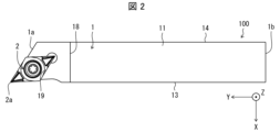
- FIG. FIG. 2 is a plan view of the cutting tool shown in FIG. 1
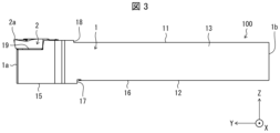
- FIG. 2 is a side view of the cutting tool shown in FIG. 1
- FIG. 2 is a rear view of the cutting tool shown in FIG. 1
- 4 is a partially enlarged view of the cutting tool shown in FIG. 3
- FIG. FIG. 6 is a cross-sectional view taken along the line VI-VI in FIG. 5
- 1 is a perspective view showing a cutting tool supported by a tool post in a non-limiting embodiment of the present disclosure
- FIG. Fig. 8 is a plan view of the cutting tool and the tool post shown in Fig. 7;
- FIG. 8 is a side view of the cutting tool and tool rest shown in FIG. 7;
- FIG. 10 is a partially enlarged view of the front portion of FIG. 9;
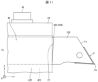
- FIG. 11 is an enlarged view of a reference example for the cutting tool shown in FIG. 10;
- 1 is a schematic diagram illustrating one step in a method for manufacturing a machined workpiece in one non-limiting example;
- FIG. 1 is a schematic diagram illustrating one step in a method for manufacturing a machined workpiece in one non-limiting example;
- FIG. 1 is a schematic diagram illustrating one step in a method for manufacturing a machined workpiece in one non-limiting example;
- FIG. 1 is a schematic diagram illustrating one step in a method for manufacturing a machined workpiece in one non-limiting example;
- Cutting tools include, for example, turning tools.
- Turning tools include, for example, grooving tools and parting off tools.
- the grooving tool can be used, for example, for grooving.
- the cutting tool 100 in one non-limiting example shown in FIG. 1 is a turning tool, and more specifically a grooving or stepping tool.
- the cutting tool 100 may comprise optional components not shown in the referenced figures.
- the dimensions of the members in each drawing do not necessarily represent the actual dimensions of the constituent members, the dimensional ratios of the respective members, and the like faithfully.
- the X-axis direction is the horizontal direction
- the Z-axis direction is the vertical direction
- the Y-axis direction is the front-back direction.
- the cutting insert 2 is located on the right side in the X-axis direction, the front side in the Y-axis direction, and the upper side in the Z-axis direction.
- the cutting insert 2 is simply referred to as "insert 2".
- a non-limiting example cutting tool 100 shown in FIGS. 1-6 includes a holder 1 , an insert 2 and a screw 3 .
- the holder 1 may be in the shape of a quadrangular prism extending from the first end 1a, which is the front end, toward the second end 1b, which is the rear end, along the first central axis L1.
- the front side of the holder 1 in the Y-axis direction is the first end 1a
- the rear side is the second end 1b.
- the size of the holder 1 is not particularly limited.
- the length in the direction along the first central axis L1 can be set to approximately 10 mm to 250 mm.
- the height from the top end to the bottom end, in other words, the width in the vertical direction of the Z-axis can be set to about 5 mm to 50 mm.
- Steel, cast iron, or the like may be used as the member of the holder 1 .
- the toughness of the holder 1 is high.
- the holder 1 has a first side surface 11 extending upward in the Z-axis direction from a first end 1a toward a second end 1b, and a second side surface 12 opposite to the first side surface 11. and have The holder 1 also has a third side surface 13 located between the first side surface 11 and the second side surface 12, and a third side surface 13 located between the first side surface 11 and the second side surface 12 and opposite to the third side surface 13. and a positioned fourth side 14 .
- the third side 13 is the right front side in FIG. 1, and the fourth side 14 is the left back side in FIG.
- the holder 1 has a leading end face 20 located on the side of the first end 1 a and a rear end face 21 located opposite to the leading end face 20 .
- the first side surface 11 may have a protruding stepped portion 18 at a location closer to the first end 1a than the second end 1b so that the tip portion 11a protrudes upward. In this case, the thickness of the tip portion 11a can be ensured, and the cutting load during cutting can be received.
- the tip portion 11a has a pocket 19 and is a portion for gripping the insert 2. As shown in FIG.
- the distal end face 20 is not limited to being perpendicular to the first central axis L1, and may be inclined from the direction perpendicular to the first central axis L1.
- the tip surface 20 need not be formed by a single plane.
- the tip surface 20 may be formed by a plurality of flat surfaces, or may be formed by curved surfaces.
- the tip surface 20 has the third side surface 13 located forward in the Y-axis direction and the fourth side surface 14 side located forward in the Y-axis direction. It is slanted so that it lies behind the
- the portion on the second end 1b side of the holder 1 may be supported by the tool post 4 when the cutting tool 100 is attached to the tool post 4 (see FIG. 7), which will be described later.
- a pocket 19 to which the insert 2 can be attached may be provided on the side of the first end 1a of the tip portion 11a.
- Pocket 19 may be a recess in which insert 2 is mounted.
- the pocket 19 is open to the tip surface 20 and the third side surface 13 .
- the pocket 19 has a bottom surface 19a with which the installation surface, which is one surface in the thickness direction of the insert 2, abuts, and two restraining side surfaces 19b perpendicular to the bottom surface 19a, with which the side surfaces of the insert 2 abut and are restrained. have.
- the bottom surface 19 a may be parallel to the second side surface 12 .
- the shape of the insert 2 is not limited to any particular configuration.
- the shape of the insert 2 may be a rod-shaped, polygonal plate-shaped or polygonal prism-shaped configuration.
- the insert 2 is in the shape of a rhombic plate, as shown in FIG. If the insert 2 is in the shape of a rhombic plate, the shape of the bottom surface 19a of the pocket 19 may be rhombic to match the shape of the mounting surface of the insert 2 .
- a corner of the upper surface of the insert 2 on the side of the first end 1a may be a cutting edge 2a.
- the cutting edge 2a is located at the intersection of the upper surface of the insert 2 substantially parallel to the first side surface 11 and the side surface of the insert 2 intersecting with the upper surface.
- the cutting edge 2a includes an end on the upper surface of the insert 2 on the side of the first end 1a.
- a through hole is provided in the center of the insert 2, and the rhombic installation surface is placed on the bottom surface 19a, and the insert 2 is fixed to the pocket 19 by inserting the screw 3 through the through hole and screwing it to the bottom surface 19a.
- Examples of materials for the insert 2 include cemented carbide and cermet.
- the cemented carbide composition may include, for example, WC--Co, WC--TiC--Co, or WC--TiC--TaC--Co.
- WC, TiC and TaC may be hard particles and Co may be the binder phase.
- the cermet may be a sintered composite material in which a metal is combined with a ceramic component.
- An example of a cermet may be a titanium compound based on titanium carbide (TiC) or titanium nitride (TiN).
- the material of the insert 2 is not limited to the above composition.
- the surface of the insert 2 may be coated with a coating formed using chemical vapor deposition (CVD) or physical vapor deposition (PVD) methods.
- the composition of the coating may include titanium carbide (TiC), titanium nitride (TiN), titanium carbonitride (TiCN), alumina (Al 2 O 3 ), or the like.
- the second side surface 12 may have a first region 15, a second region 16, and a stepped portion 17.
- the first region 15 is, for example, a flat region located on the side of the first end 1a.
- the second region 16 is, for example, a flat region located closer to the second end 1 b than the first region 15 and closer to the first side surface 11 than the first region 15 .
- the step portion 17 connects the first region 15 and the second region 16, for example.
- the stepped portion 17 is located closer to the second end 1b than the projecting stepped portion 18 is.
- the stepped portion 17 is a portion for positioning the cutting tool 100 on the tool post 4 and is engaged with the tool post 4 .
- the positioning member is not a separate member from the cutting tool holder, but a part of the holder 1 . Therefore, it is not necessary to consider the machining accuracy of the portion of the holder to which the positioning member is attached and the attachment accuracy when attaching the positioning member to the holder.
- the stepped portion 17 has a curved shape that protrudes toward the second end 1b in a cross section parallel to the first region 15.
- the stepped portion 17 has a curved shape that protrudes toward the second end 1b in the cross section described above, and has a curved surface that has a constant width in the Y-axis direction. If the stepped portion 17 has a linear shape in the cross section described above, that is, if the stepped portion 17 is provided so as to extend straight in the X-axis direction in FIG. may be extremely inclined toward the first end 1a side or the second end 1b side.
- FIG. 11 shows the blade post when the stepped portion 17 is formed so as to extend straight in the Z-axis direction, and the stepped portion 17 is inclined toward the first end 1a due to a processing error.
- 4 is an enlarged side view showing a state in which the right corner of the locking portion of 4 is in contact with the stepped portion 17.
- FIG. 11 Even if the holder 1 and the tool post 4 are elastically deformed, under the condition that the stepped portion 17 is extremely inclined as described above, the contact area of the locking portion of the holder 1 and the tool post 4 is limited, and substantially , the situation remains the same as that of point contact.
- the stepped portion 17 is configured to form a convex curved shape toward the second end 1b, it makes point contact with the engaging portion of the tool post 4 along the curved line, and actually makes surface contact due to elastic deformation. Stable positioning can be easily performed (see FIG. 10). Even if a machining error occurs in the stepped portion 17, the error is absorbed by the curved line. When a cutting load is applied, the load is absorbed, and the positioning accuracy, in other words, the attachment accuracy to the tool rest 4 can be maintained, and the machining accuracy of cutting is excellent.
- the stepped portion 17 may have an arc shape in the cross section described above. In this case, it is possible to further reduce the influence when a machining error occurs in the step portion 17 .
- At least part of the stepped portion 17 may be located in a region where the pocket 19 is extended toward the second end 1b. In this case, at least a part of the stepped portion 17 is located behind the pocket 19, and can absorb the cutting load during cutting, thereby maintaining good positioning accuracy.
- the stepped portion 17 may be in contact with the third side surface 13 and the fourth side surface 14 .
- the stepped portion 17 is provided over the entire width of the second side surface 12, which has high durability against cutting load and can maintain good positioning accuracy.
- the stepped portion 17 has a tip portion 17a positioned closest to the second end 1b, and the length from the tip portion 17a to the fourth side surface 14 is longer than the tip portion 17a.
- the length from 17a to the third side surface 13 may be short. In this case, the thickness of the tip portion 11a having the pocket 19 can be ensured, and the durability against the cutting load is increased.
- the tip portion 17a may be in contact with the third side surface 13.
- the stepped portion 17 is provided over a wide range of the second side surface 12 and has high durability against cutting load.
- the second side surface 12 on which the stepped portion 17 is formed may be separated from the pocket 19 .
- the cutting load is better than forming the stepped portion 17 on the first side surface 11 or the third side surface 13 on which the pocket 19 is formed. can be received, and the positioning accuracy is good.
- the stepped portion 17 is provided on the second side surface 12 , but the present invention is not limited to this. As will be described later, it may be provided on the first side surface 11 or the third side surface 13 that can be engaged with the tool post 4 .
- FIG. 7 is a perspective view showing a state in which the cutting tool 100 is supported by the tool post 4 according to a non-limiting embodiment of the present disclosure.
- 8 is a plan view of the cutting tool 100 and the tool post 4 shown in FIG. 7.
- FIG. 9 is a side view of the cutting tool 100 and the tool post 4 shown in FIG. 7 of FIG. 8.
- FIG. 10 is an enlarged side view of a portion of the front portion of FIG. 9.
- the X-axis direction is the horizontal direction
- the Z-axis direction is the vertical direction
- the Y-axis direction is the front-back direction.
- the side where the insert 2 is located is the right side in the X-axis direction
- the side where the fourth side surface 14 is located is the upper side in the Z-axis direction.
- the tool post 4 has a base 41 , a plurality of support portions 42 , screw holes 43 , a holding portion 44 and set screws 45 .
- the base 41 has the shape of a rectangular plate whose dimension in the X-axis direction is longer than the dimension in the Y-axis direction.
- a plurality of support portions 42 extending in the Y-axis direction are provided on the base 41 in a comb shape.
- a tool post provided with a plurality of support portions 42 in a comb-like shape is generally called a comb-tooth tool post.
- the support portion 42 has a right side 421 , a left side 422 , a front end surface 423 and a bottom surface 425 .
- the bottom surface 425 is the bottom of the comb-shaped groove and faces upward.
- Right side 421 rises upward from bottom 425 .
- the left side surface 422 has a shape that rises upward from the bottom surface 425 and then tilts upward to the right.
- the front end surface 423 is located on the front side between the right side surface 421 and the left side surface 422 .
- the holding portion 44 is L-shaped when viewed from the front.
- the clamping part 44 is inserted between the cutting tool 100 and the left side surface 422 with the L-shaped vertical side abutting on the oblique portion of the left side 422, and the set screw 45 is inserted through the L-shaped horizontal side. By doing so, it is screwed into the screw hole 43 of the support portion 42 .
- the cutting tool 100 faces the first side surface 11 to the right so that the tip portion 11a is positioned forward, and the right corner portion 424 of the front end surface 423 of the support portion 42 is locked to the stepped portion 17. It is placed between the supporting portion 42 and the supporting portion 42 .
- the stepped portion 17 has a convex curved shape toward the second end 1b in a cross-sectional view. Therefore, as shown in FIG. and can be positioned well.
- the cutting tool 100 is fixed to the tool post 4 by inserting the holding portion 44 between the first side surface 11 and the adjacent support portion 42 and screwing the setscrew 45 into the screw hole 43 . .
- the right corner portion 424 can come into surface contact with the stepped portion 17 even if a machining error occurs in the stepped portion 17 .
- the load is absorbed and the positioning accuracy is maintained.
- FIG. 11 shows the right corner portion 424 when the stepped portion 27 is inclined toward the first end 1a due to a processing error when the stepped portion is provided so as to extend straight in the Z-axis direction. is in contact with the stepped portion 27; As shown in FIG. 11, the right corner portion 424 is in point contact with the stepped portion 27, which makes it easy to move and difficult to position.
- a plurality of cutting tools 100 are supported between the support portions 42 , 42 .
- the cutting tool 100 can be well positioned in the Y-axis direction, and the protrusion amount of the tip portion 11a from the base 41 can be well aligned between the cutting tools 100. . Therefore, the same work material can be machined in sequence with a plurality of cutting tools 100 with high accuracy. Even if a cutting load is applied during cutting, it can be absorbed by the stepped portion 17, and the positioning accuracy can be maintained.
- the stepped portion 17 may have a groove shape recessed toward the first side surface 11 .
- the stepped portion 17 may have a bottom surface 17 b closest to the first side surface 11 . It can also be said that the bottom surface 17 b is positioned closest to the first side surface 11 in the stepped portion 17 . At this time, the bottom surface 17b may be positioned closer to the first side surface 11 than the second region 16, as in the example shown in FIG.
- a wall surface rising from the bottom surface 17b of the stepped portion 17 and facing the bottom surface 17b is referred to as a wall surface 17c shown in FIG.
- the strength of the boundary between the bottom surface 17b and the wall surface 17c tends to be relatively small.
- the cutting tool 100 is attached to the tool post 4
- if the right corner portion 424 comes into contact with this boundary cracks may occur at the boundary.
- the stepped portion 17 has the above configuration, it is difficult for the right corner portion 424 to come into contact with the above boundary. Therefore, deterioration of the strength of the holder 1 can be avoided.
- the height h1 from the bottom surface 17b to the second region 16 may be smaller than the height h2 from the second region 16 to the first region 15.
- “height” means the width in the vertical direction of the Z-axis.
- a workpiece 101 is produced by cutting a workpiece 103 .
- the manufacturing method of the cut workpiece 101 in the embodiment includes the following steps. i.e. (1) a step of rotating the work material 103; (2) A step of contacting the rotating work material 103 with the cutting tool 100 represented by the above embodiment; (3) separating the cutting tool 100 from the work material 103; Prepare.
- the cutting tool 100 is moved in the forward direction of the Y-axis with the second central axis L2 fixed and the work material 103 rotated. bring closer.
- the cutting tool 100 is moved downward along the Z-axis and forward along the Y-axis while at least a part of the portion of the insert 2 that is used as the cutting edge 2a of the insert 2 is in contact with the rotating workpiece 103.
- the work material 103 is cut by moving in the direction.
- the cutting tool 100 is moved away from the work material 103 by moving the cutting tool 100 in the backward direction of the Y-axis while the work material 103 is being rotated.
- the cutting tool 100 is brought into contact with the work material 103 or separated from the work material 103 by moving the cutting tool 100, but the present invention is not limited to this case.
- step (1) the work material 103 may be brought closer to the cutting tool 100 .
- step (3) the work material 103 may be kept away from the cutting tool 100 .
- Another cutting tool 100 supported on the tool rest 4 may be used to continuously cut the material 103 to be cut.
- Representative examples of the material of the work material 103 include hardened steel, carbon steel, alloy steel, stainless steel, cast iron, non-ferrous metals, and the like.
- the cutting tool 100 of the present disclosure is satisfactorily positioned on the tool post 4 and the holder 1 by the stepped portion 17, so that machining can be performed with high accuracy.
- the amount of protrusion from the base 41 can be made uniform, so machining can be performed in sequence with high accuracy.
Abstract
ホルダは、第1端から第2端に向かって延びた四角柱形状である。ホルダは、第1端の側に位置するポケットと、第1端から第2端に向かってそれぞれ延びた第1側面及び第2側面と、を有する。第2側面は、第1端の側に位置する平坦な第1領域と、第1領域よりも第2端の近く、且つ、第1領域よりも第1側面の近くに位置する平坦な第2領域と、第1領域及び第2領域を接続する段差部と、を有する。そして、段差部は、第1領域に平行な断面において、第2端に向かって凸の曲線状をなす。
Description
本開示は、金属等の被削材を切削加工する際に用いられる切削工具におけるホルダ、切削工具、及び切削加工物の製造方法に関する。
金属等の被削材を切削加工する際に用いられる切削工具として、例えば特許文献1及び2に記載の切削工具が知られている。特許文献1及び2に記載の切削工具は、刃物台に取り付けられた状態で使用される。刃物台への取り付け精度の向上のため、特許文献1に記載の切削工具においては、板状の位置決め部材が工具本体に取り付けられ、位置決め部材の後端部が刃物台に当接される。特許文献2に記載の切削工具においては、位置決めピンが本体部に装着され、位置決めピンが刃物台の突当面へ突き当てられる。
本開示における限定されない一例のホルダは、第1端から第2端に向かって延びた四角柱形状である。ホルダは、前記第1端の側に位置し、且つ、切削インサートを取り付け可能なポケットと、前記第1端から前記第2端に向かって延びた第1側面と、前記第1側面の反対に位置する第2側面と、を有する。前記第2側面は、前記第1端の側に位置する平坦な第1領域と、前記第1領域よりも前記第2端の近く、且つ、前記第1領域よりも前記第1側面の近くに位置する平坦な第2領域と、前記第1領域及び前記第2領域を接続する段差部と、を有する。そして、前記段差部は、前記第1領域に平行な断面において、前記第2端に向かって凸の曲線状をなす。
本開示における限定されない一例のホルダ、切削工具、及び切削化合物の製造方法について、図面を用いて詳細に説明する。切削工具としては、例えば、旋削工具が挙げられる。旋削工具としては、例えば、溝入れ工具及び突っ切り工具が挙げられる。溝入れ工具は、例えば、溝入れ加工に用いることが可能である。図1に示す限定されない一例における切削工具100は、旋削工具であり、より具体的には、溝又は段差を入れる工具である。以下で参照する各図では、説明の便宜上、限定されない実施形態を構成する部材における主要な部材のみが簡略化して示される。従って、切削工具100は、参照する各図に示されていない任意の構成部材を備え得る。また、各図中の部材の寸法は、実際の構成部材の寸法及び各部材の寸法比率等を忠実に表すとは限らない。
各図におけるX軸方向を左右方向とし、Z軸方向を上下方向とし、Y軸方向を前後方向とする。図1において、切削インサート2が位置する方をX軸方向における右の方とし、Y軸方向における前の方とし、Z軸方向における上の方とする。以下、切削インサート2を単に「インサート2」と言う。
図1~図6に示す限定されない一例の切削工具100は、ホルダ1、インサート2、及びネジ3を有する。
<ホルダ>
ホルダ1は、第1中心軸L1に沿って、先端である第1端1aから後端である第2端1bに向かって延びた四角柱形状であってもよい。図1においては、ホルダ1のY軸方向の前の方が第1端1a、後の方が第2端1bである。
ホルダ1は、第1中心軸L1に沿って、先端である第1端1aから後端である第2端1bに向かって延びた四角柱形状であってもよい。図1においては、ホルダ1のY軸方向の前の方が第1端1a、後の方が第2端1bである。
ホルダ1の大きさは特に限定されない。例えば、第1中心軸L1に沿った方向における長さは、10mm~250mm程度に設定できる。また、上端から下端までの高さ、言い換えればZ軸の上下方向における幅は、5mm~50mm程度に設定できる。
ホルダ1の部材としては、鋼、鋳鉄等が用いられてもよい。特に、これらの部材の中で鋼が用いられた場合には、ホルダ1の靱性が高い。
図1に示すように、ホルダ1は、Z軸方向における上方で第1端1aから第2端1bに向かって延びた第1側面11と、第1側面11の反対に位置する第2側面12と、を有する。また、ホルダ1は、第1側面11及び第2側面12の間に位置する第3側面13と、第1側面11及び第2側面12の間に位置し、且つ、第3側面13の反対に位置する第4側面14と、を有する。第3側面13は図1における右手前の面であり、第4側面14は図1における左奥の面である。ホルダ1は、第1端1aの側に位置する先端面20と、先端面20の反対に位置する後端面21と、を有する。
第1側面11は、先端部分11aが上方に突出するように、第2端1bよりも第1端1aに近い箇所に突出段差部18を有してもよい。この場合、先端部分11aの肉厚を確保でき、切削加工時の切削負荷を受け止めることができる。先端部分11aは、ポケット19を有し、インサート2を把持する部位である。
先端面20は、第1中心軸L1に直交する場合に限定されず、第1中心軸L1に直交する方向から傾斜していてもよい。また、先端面20は、1つの平面によって形成される必要はない。例えば、先端面20は、複数の平面によって形成されてもよく、また、曲面によって形成されてもよい。図1に示す例では、菱形板状のインサート2の形状に合わせて、先端面20は、第3側面13の側がY軸方向の前の方に位置し、第4側面14の側がY軸方向の後の方に位置するように傾斜している。
ホルダ1の第2端1bの側の部分は、後述する刃物台4(図7参照)に切削工具100を取り付ける際に、刃物台4によって支持されてもよい。
<ポケット>
先端部分11aの第1端1aの側には、インサート2を取り付け可能なポケット19が設けられていてもよい。ポケット19は、インサート2が取り付けられる窪みであってもよい。図1に示す例では、ポケット19は、先端面20及び第3側面13に対して開口している。ポケット19は、インサート2の厚み方向の一方の面である設置面が当接する底面19aと、底面19aに直角であり、インサート2の側面が当接して拘束される2つの拘束側面19bと、を有する。底面19aは、第2側面12に平行であってもよい。
先端部分11aの第1端1aの側には、インサート2を取り付け可能なポケット19が設けられていてもよい。ポケット19は、インサート2が取り付けられる窪みであってもよい。図1に示す例では、ポケット19は、先端面20及び第3側面13に対して開口している。ポケット19は、インサート2の厚み方向の一方の面である設置面が当接する底面19aと、底面19aに直角であり、インサート2の側面が当接して拘束される2つの拘束側面19bと、を有する。底面19aは、第2側面12に平行であってもよい。
<インサート>
インサート2の形状は特定の構成に限定されない。例えば、インサート2の形状は、棒形状、多角板形状または多角柱形状の構成であってもよい。本実施形態においてインサート2は、図1に示すように、菱形板の形状である。インサート2が菱形板の形状である場合、ポケット19の底面19aの形状は、インサート2の設置面の形状に合わせて、菱形であってもよい。
インサート2の形状は特定の構成に限定されない。例えば、インサート2の形状は、棒形状、多角板形状または多角柱形状の構成であってもよい。本実施形態においてインサート2は、図1に示すように、菱形板の形状である。インサート2が菱形板の形状である場合、ポケット19の底面19aの形状は、インサート2の設置面の形状に合わせて、菱形であってもよい。
インサート2の上面における第1端1aの側の一角は切刃2aとされていてもよい。具体的には、第1側面11に概ね平行なインサート2の上面と、この上面に対して交差するインサート2の側面との交わりに切刃2aが位置する。切刃2aは、インサート2の上面における第1端1aの側の端部を含んでいる。インサート2の中央部には貫通孔が設けられ、菱形の設置面を底面19aに載置し、この貫通孔にネジ3を挿通して底面19aにネジ止めすることによってインサート2がポケット19に固定されてもよい。
インサート2の材質としては、例えば、超硬合金及びサーメット等が挙げられ得る。超硬合金の組成としては、例えば、WC-Co、WC-TiC-Co、またはWC-TiC-TaC-Co等が挙げられ得る。ここで、WC、TiC、及びTaCは硬質粒子であってもよく、Coは結合相であってもよい。
また、サーメットは、セラミック成分に金属を複合させた焼結複合材料であってもよい。サーメットの一例として、炭化チタン(TiC)又は窒化チタン(TiN)を主成分としたチタン化合物が挙げられ得る。インサート2の材質は、上記の組成に限定されない。
インサート2の表面は、化学蒸着(CVD)法又は物理蒸着(PVD)法を用いて形成した被膜でコーティングされてもよい。被膜の組成としては、炭化チタン(TiC)、窒化チタン(TiN)、炭窒化チタン(TiCN)、またはアルミナ(Al2O3)等が挙げられ得る。
<第2側面と段差部>
図2~図4に示すように、第2側面12は、第1領域15と、第2領域16と、段差部17と、を有してもよい。第1領域15は、例えば、第1端1aの側に位置する平坦な領域である。第2領域16は、例えば、第1領域15よりも第2端1bの近くに位置し、且つ、第1領域15よりも第1側面11の近くに位置する平坦な領域である。段差部17は、例えば、第1領域15及び第2領域16を接続する。図3に示すように、本実施形態では、段差部17は、突出段差部18より第2端1bの側に位置している。
図2~図4に示すように、第2側面12は、第1領域15と、第2領域16と、段差部17と、を有してもよい。第1領域15は、例えば、第1端1aの側に位置する平坦な領域である。第2領域16は、例えば、第1領域15よりも第2端1bの近くに位置し、且つ、第1領域15よりも第1側面11の近くに位置する平坦な領域である。段差部17は、例えば、第1領域15及び第2領域16を接続する。図3に示すように、本実施形態では、段差部17は、突出段差部18より第2端1bの側に位置している。
段差部17は、刃物台4に切削工具100を位置決めするための部位であり、刃物台4に係止される。本開示の切削工具100においては、特許文献1及び2の切削工具の位置決め構造と異なり、位置決め部材は切削工具のホルダと別の部材ではなく、ホルダ1の一部である。従って、位置決め部材が取り付けられるホルダの部分の加工精度、及び位置決め部材をホルダに取り付ける際の取付精度を考慮する必要がない。
段差部17は、図5のVI-VI線矢視図である図6に示すように、第1領域15に平行な断面において、第2端1bに向かって凸の曲線状をなす。図5及び図6に示すように、段差部17は、上述の断面において第2端1bに向かって凸の曲線状をなすとともに、Y軸方向に対し一定の幅を有する曲面状をなす。段差部17が上述の断面において直線状をなす場合、即ち、図6において段差部17をX軸方向に真っ直ぐに延びるように設けることにした場合、段差部17の加工時に、誤差により段差部17が第1端1aの側あるいは第2端1bの側に極端に傾くことがある。
この場合、刃物台4の係止部分と点接触することになる(図11参照)。図11は、段差部17をZ軸方向に真っ直ぐに延びるように設けることにした場合において、加工ミスにより生じた段差部17が第1端1aの側に傾いて形成された際の、刃物台4の係止部分の右角部が段差部17に当接した状態を示す拡大側面図である。仮に、ホルダ1及び刃物台4が弾性変形したとしても、上記したように段差部17が極端に傾いた状況下では、ホルダ1及び刃物台4の係止部分の接触領域が限定され、実質的には点接触と変わらない状況に留まる。このような点接触では、切削加工によって切削負荷がかかったときに、刃物台4で切削負荷を受け止めきれずにホルダ1が動いてしまうおそれがある。結果として、ホルダ1の位置決めができず、切削の加工精度が悪くなる。
一方、段差部17が第2端1bに向かって凸の曲線状をなす構成とすることで、刃物台4の係止部分に曲線で点接触し、実際には弾性変形により面接触するので、安定した位置決めを容易に行うことができる(図10参照)。段差部17の加工誤差が生じたときにおいても、曲線であるので、誤差は吸収される。そして、切削負荷がかかったときに負荷が吸収され、位置決め精度、換言すれば刃物台4への取付精度を維持でき、切削の加工精度が良好である。
段差部17は、上述の断面において円弧形状であってもよい。この場合、段差部17の加工誤差が生じたときの影響をより低減できる。
第2側面12を正面視した場合に、段差部17の少なくとも一部は、ポケット19を第2端1bに向かって引き延ばした領域に位置してもよい。この場合、段差部17の少なくとも一部はポケット19の後ろ側に位置し、切削加工時に切削負荷を吸収することができ、良好な位置決め精度を維持できる。
段差部17は、第3側面13及び第4側面14に接していてもよい。この場合、段差部17は第2側面12の全幅に亘って設けられており、切削負荷に対する耐久性が高く、良好な位置決め精度を維持できる。
図4及び図6に示すように、段差部17は、第2端1bに対して最も近くに位置する先端部17aを有し、先端部17aから第4側面14までの長さよりも、先端部17aから第3側面13までの長さが短くてもよい。この場合、ポケット19を有する先端部分11aの肉厚を確保でき、切削負荷に対する耐久性が大きくなる。
先端部17aは、第3側面13に接していてもよい。この場合、段差部17は第2側面12の広い範囲に亘って設けられており、切削負荷に対する耐久性が高い。
図3に示すように、段差部17が形成されている第2側面12はポケット19から離れていてもよい。ポケット19から離れている第2側面12に段差部17を形成することで、ポケット19が形成されている第1側面11又は第3側面13に段差部17を形成するよりも、切削負荷を良好に受け止めることができ、位置決め精度が良好である。
上述の切削工具100においては、段差部17が第2側面12に設けられている場合につき説明しているが、これに限定されない。後述するように、刃物台4に係止され得る第1側面11、又は第3側面13に設けてもよい。
<刃物台への取り付け構造>
以下、図7は、本開示の限定されない実施形態における切削工具100が刃物台4に支持された状態を示す斜視図である。図8は、図7に示す切削工具100及び刃物台4の平面図である。図9は、図8の図7に示す切削工具100及び刃物台4の側面図である。図10は、図9の前側部分の一部を拡大した側面図である。
以下、図7は、本開示の限定されない実施形態における切削工具100が刃物台4に支持された状態を示す斜視図である。図8は、図7に示す切削工具100及び刃物台4の平面図である。図9は、図8の図7に示す切削工具100及び刃物台4の側面図である。図10は、図9の前側部分の一部を拡大した側面図である。
各図におけるX軸方向を左右方向とし、Z軸方向を上下方向とし、Y軸方向を前後方向とする。図7において、インサート2が位置する方をX軸方向における右の方とし、Y軸方向における前の方とし、第4側面14が位置する方をZ軸方向における上の方とする。
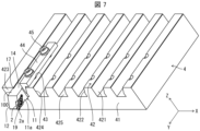
図7に示すように、刃物台4は、基台41と、複数の支持部42と、ネジ孔43と、挟持部44と、止めネジ45と、を有する。基台41は、X軸方向の寸法がY軸方向の寸法より長い角板状をなす。基台41上には、Y軸方向に延びる支持部42が、櫛歯状に複数設けられている。図7に示すように複数の支持部42が櫛歯状に設けられた刃物台は、一般的に櫛歯刃物台と呼ばれる。
支持部42は、右側面421と、左側面422と、前端面423と、底面425と、を有する。底面425は、櫛歯状の溝における底であって上方を向いている。右側面421は、底面425から上方に起立する。左側面422は、底面425から上方に起立した後、右斜め上に傾いた形状を有する。前端面423は、右側面421と、左側面422との間の前側に位置する。
支持部42の前寄りに、ネジ孔43が2個設けられている。挟持部44は、前方から見てL字状をなす。挟持部44は、L字の縦辺部が左側面422の斜め部分に当接する状態で、切削工具100と左側面422との間に挿入され、L字の横辺部に止めネジ45を挿通することにより、支持部42のネジ孔43にネジ止めされる。
切削工具100は、先端部分11aが前方に位置するように、第1側面11を右方に向け、段差部17に支持部42の前端面423の右角部424が係止された状態で、隣接する支持部42との間に載置される。上述したように、段差部17は、断面視において、第2端1bに向かって凸の曲線状をなすので、図10に示すように、段差部17は右角部424と面接触にて当接でき、良好に位置決めができる。この状態で、第1側面11と隣接する支持部42との間に挟持部44を挿入し、止めネジ45をネジ孔43にネジ止めすることにより、切削工具100が刃物台4に固定される。曲線状に形成するので、段差部17の加工誤差が生じた場合においても、右角部424は段差部17に面接触にて当接できる。切削加工時に段差部17に負荷がかかったときに負荷は吸収され、位置決め精度は維持される。
図11は、段差部をZ軸方向に真っ直ぐに延びるように設けることにした場合に、加工ミスにより生じた段差部27が第1端1aの側に傾いて形成されたときに、右角部424を段差部27に当接した状態を示す拡大側面図である。図11に示すように、右角部424は段差部27と点接触することになり、動きやすく、位置決めが困難である。
支持部42,42間には、複数の切削工具100が支持される。本開示の切削工具100によれば、切削工具100のY軸方向における位置決めを良好に行うことができ、先端部分11aの基台41からの突出量を切削工具100間で良好に揃えることができる。従って、同一の被削材に対し、複数の切削工具100により順に精度良く加工することができる。切削加工時に、切削負荷がかかった場合においても、段差部17により吸収することができ、位置決め精度を維持することができる。
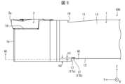
図4及び図5に示す一例のように、段差部17は、第1側面11に向かって窪んだ溝形状であってもよい。このとき、段差部17は、第1側面11に最も近づく底面17bを有してもよい。底面17bは、段差部17において第1側面11の最も近くに位置するとも言える。このとき、図5に示す一例のように、底面17bは、第2領域16よりも第1側面11の近くに位置してもよい。
段差部17の底面17bから立ち上がり、底面17bの側に面する壁面を、図5に示す壁面17cとする。この場合、段差部17において、底面17b及び壁面17cの境界は強度が相対的に小さくなりやすい。切削工具100を刃物台4に取り付ける際に、この境界に右角部424が当接すると、上記の境界にクラックが生じるおそれがある。しかしながら、段差部17が上記の構成である場合には、上記の境界に右角部424が当接しにくい。そのため、ホルダ1の強度の低下が避けられる。
段差部17が底面17bを有する場合において、底面17bから第2領域16までの高さh1が、第2領域16から第1領域15までの高さh2より小さくてもよい。ここで、「高さ」とは、Z軸の上下方向における幅を意味する。高さh1が相対的に小さい場合には、底面17b及び第1側面11の間でのホルダ1の肉厚が過度に小さくなることが避けられる。また、高さh2が相対的に大きい場合には、段差部17によるホルダ1の刃物台4への位置決め精度が高く確保される。
<切削加工物の製造方法>
次に、本開示における限定されない一面の切削加工物の製造方法について図面を用いて説明する。
次に、本開示における限定されない一面の切削加工物の製造方法について図面を用いて説明する。
切削加工物101は、被削材103を切削加工することによって作製される。実施形態における切削加工物101の製造方法は、以下の工程を備える。すなわち、
(1)被削材103を回転させる工程と、
(2)回転している被削材103に上記実施形態に代表される切削工具100を接触させる工程と、
(3)切削工具100を被削材103から離す工程と、
を備える。
(1)被削材103を回転させる工程と、
(2)回転している被削材103に上記実施形態に代表される切削工具100を接触させる工程と、
(3)切削工具100を被削材103から離す工程と、
を備える。
より具体的には、まず、図12に示すように、被削材103を第2中心軸L2の周りで回転させるとともに、切削工具100を支持した刃物台4を、被削材103に相対的に近付ける。次に、図13に示すように、切削工具100における切刃2aの少なくとも一部を被削材103に接触させて、被削材103を切削する。そして、図14に示すように、切削工具100を被削材103または切削加工物101から相対的に遠ざける。
図12に示すように、第2中心軸L2を固定するとともに被削材103を回転させた状態で切削工具100をY軸の前方向に移動させることによって、切削工具100を被削材103に近づける。
図13に示すように、回転している被削材103にインサート2における切刃2aとして用いられる部分の少なくとも一部を接触させた状態で切削工具100をZ軸の下方向及びY軸の前方向に移動させることによって、被削材103を切削する。
図14に示すように、被削材103を回転させた状態で切削工具100をY軸の後方向に移動させることによって、切削工具100を被削材103から遠ざける。
それぞれの工程において、切削工具100を動かすことによって、切削工具100を被削材103に接触させる、あるいは、切削工具100を被削材103から離しているが、この場合に限定されない。
例えば、(1)の工程において、被削材103を切削工具100に近づけてもよい。(3)の工程において、被削材103を切削工具100から遠ざけてもよい。切削加工を継続する場合には、被削材103を回転させた状態を維持して、被削材103の異なる箇所にインサート2における切刃2aの少なくとも一部を接触させる工程を繰り返してもよい。刃物台4に支持した他の切削工具100により、続けて被削材103に切削加工を行ってもよい。
被削材103の材質の代表例としては、焼入鋼、炭素鋼、合金鋼、ステンレス、鋳鉄、又は非鉄金属等が挙げられ得る。
本開示の切削加工物の製造方法によれば、本開示の切削工具100が段差部17により刃物台4に良好にホルダ1に位置決めされているので、精度良く加工を行うことができる。そして、複数の切削工具100を刃物台4に支持して切削加工を行う場合、基台41からの突出量を均一にできるので、順に精度良く加工を行うことができる。
1・・・ホルダ
1a・・第1端(先端)
1b・・第2端(後端)
11・・・第1側面
12・・・第2側面
13・・・第3側面
14・・・第4側面
15・・・第1領域
16・・・第2領域
17・・・段差部
17b・・底面
17c・・壁面
18・・・突出段差部
19・・・ポケット
20・・・先端面
21・・・後端面
2・・・切削インサート(インサート)
2a・・切刃
3・・・ネジ
4・・・刃物台
41・・・基台
42・・・支持部
43・・・ネジ孔
44・・・挟持部
45・・・止めネジ
100・・・切削工具
101・・・切削加工物
103・・・被削材
L1・・・第1中心軸
L2・・・第2中心軸
1a・・第1端(先端)
1b・・第2端(後端)
11・・・第1側面
12・・・第2側面
13・・・第3側面
14・・・第4側面
15・・・第1領域
16・・・第2領域
17・・・段差部
17b・・底面
17c・・壁面
18・・・突出段差部
19・・・ポケット
20・・・先端面
21・・・後端面
2・・・切削インサート(インサート)
2a・・切刃
3・・・ネジ
4・・・刃物台
41・・・基台
42・・・支持部
43・・・ネジ孔
44・・・挟持部
45・・・止めネジ
100・・・切削工具
101・・・切削加工物
103・・・被削材
L1・・・第1中心軸
L2・・・第2中心軸
Claims (11)
- 第1端から第2端に向かって延びた四角柱形状であって、
前記第1端の側に位置し、且つ、切削インサートを取り付け可能なポケットと、
前記第1端から前記第2端に向かって延びた第1側面と、
前記第1側面の反対に位置する第2側面と、を有し、
前記第2側面は、
前記第1端の側に位置する平坦な第1領域と、
前記第1領域よりも前記第2端の近く、且つ、前記第1領域よりも前記第1側面の近くに位置する平坦な第2領域と、
前記第1領域及び前記第2領域を接続する段差部と、を有し、
前記段差部は、前記第1領域に平行な断面において、前記第2端に向かって凸の曲線状をなす、ホルダ。 - 前記第2側面を正面視した場合に、前記段差部の少なくとも一部が、前記ポケットを前記第2端に向かって引き延ばした領域に位置する、請求項1に記載のホルダ。
- 前記段差部は、前記第1領域に平行な断面において、円弧形状をなす、請求項1又は2に記載のホルダ。
- 前記第2側面は、前記ポケットから離れている、請求項1~3のいずれか1項に記載のホルダ。
- 前記第1側面及び前記第2側面の間に位置する第3側面と、
前記第1側面及び前記第2側面の間に位置し、且つ、前記第3側面の反対に位置する第4側面と、をさらに有し、
前記ポケットは、前記第1側面及び前記第3側面に対して開口し、
前記段差部が、前記第3側面及び前記第4側面に接している、請求項1~4のいずれか1項に記載のホルダ。 - 前記第1領域に平行な断面において、
前記段差部は、前記第2端に対して最も近くに位置する先端部を有し、
前記先端部から前記第4側面までの長さよりも、前記先端部から前記第3側面までの長さが短い、請求項5に記載のホルダ。 - 前記先端部が、前記第3側面に接する、請求項6に記載のホルダ。
- 前記段差部は、前記第1側面に向かって窪んだ溝形状であって、前記第1側面に最も近づく底面を有し、
前記底面は、前記第2領域よりも前記第1側面の近くに位置する、請求項1~7のいずれか1項に記載のホルダ。 - 前記底面から前記第2領域までの高さが、前記第2領域から前記第1領域までの高さよりも小さい、請求項8に記載のホルダ。
- 請求項1~9のいずれか1項に記載のホルダと、
前記ポケットに位置する切削インサートと、を備えた切削工具。 - 被削材を回転させる工程と、
回転している前記被削材に請求項10に記載の切削工具を接触させる工程と、
前記切削工具を前記被削材から離す工程と、を有する切削加工物の製造方法。
Priority Applications (1)
| Application Number | Priority Date | Filing Date | Title |
|---|---|---|---|
| CN202280064429.XA CN117980097A (zh) | 2021-10-06 | 2022-10-03 | 刀柄、切削刀具以及切削加工物的制造方法 |
Applications Claiming Priority (2)
| Application Number | Priority Date | Filing Date | Title |
|---|---|---|---|
| JP2021164670 | 2021-10-06 | ||
| JP2021-164670 | 2021-10-06 |
Publications (1)
| Publication Number | Publication Date |
|---|---|
| WO2023058588A1 true WO2023058588A1 (ja) | 2023-04-13 |
Family
ID=85804224
Family Applications (1)
| Application Number | Title | Priority Date | Filing Date |
|---|---|---|---|
| PCT/JP2022/036897 WO2023058588A1 (ja) | 2021-10-06 | 2022-10-03 | ホルダ、切削工具、及び切削加工物の製造方法 |
Country Status (2)
| Country | Link |
|---|---|
| CN (1) | CN117980097A (ja) |
| WO (1) | WO2023058588A1 (ja) |
Citations (4)
| Publication number | Priority date | Publication date | Assignee | Title |
|---|---|---|---|---|
| JP2002346808A (ja) * | 2001-03-19 | 2002-12-04 | Suzuki Seiko:Kk | 旋盤用バイトユニット |
| US20160136733A1 (en) * | 2014-11-19 | 2016-05-19 | Kennametal Inc. | Tool holder for a cutting insert |
| JP2020028943A (ja) * | 2018-08-22 | 2020-02-27 | 京セラ株式会社 | ホルダ、切削工具及び切削加工物の製造方法 |
| JP2020104219A (ja) * | 2018-12-27 | 2020-07-09 | 三菱マテリアル株式会社 | 切削インサートおよび刃先交換式切削工具 |
-
2022
- 2022-10-03 WO PCT/JP2022/036897 patent/WO2023058588A1/ja active Application Filing
- 2022-10-03 CN CN202280064429.XA patent/CN117980097A/zh active Pending
Patent Citations (4)
| Publication number | Priority date | Publication date | Assignee | Title |
|---|---|---|---|---|
| JP2002346808A (ja) * | 2001-03-19 | 2002-12-04 | Suzuki Seiko:Kk | 旋盤用バイトユニット |
| US20160136733A1 (en) * | 2014-11-19 | 2016-05-19 | Kennametal Inc. | Tool holder for a cutting insert |
| JP2020028943A (ja) * | 2018-08-22 | 2020-02-27 | 京セラ株式会社 | ホルダ、切削工具及び切削加工物の製造方法 |
| JP2020104219A (ja) * | 2018-12-27 | 2020-07-09 | 三菱マテリアル株式会社 | 切削インサートおよび刃先交換式切削工具 |
Also Published As
| Publication number | Publication date |
|---|---|
| CN117980097A (zh) | 2024-05-03 |
Similar Documents
| Publication | Publication Date | Title |
|---|---|---|
| JP6685531B2 (ja) | 切削インサート、切削工具及び切削加工物の製造方法 | |
| JP2012045692A (ja) | 切削工具および切削工具を用いた被削材の切削方法 | |
| WO2021193709A1 (ja) | 切削インサート、切削工具及び切削加工物の製造方法 | |
| WO2023058588A1 (ja) | ホルダ、切削工具、及び切削加工物の製造方法 | |
| JP7368064B2 (ja) | 工作機械及び切削加工物の製造方法 | |
| JP2020028943A (ja) | ホルダ、切削工具及び切削加工物の製造方法 | |
| CN110944777B (zh) | 切削刀片、切削工具以及切削加工物的制造方法 | |
| KR101291887B1 (ko) | 브로치 공구 및 브로치 인서트 | |
| JP7480291B2 (ja) | 切削インサート、切削工具及び切削加工物の製造方法 | |
| WO2023176441A1 (ja) | 切削工具及び切削加工物の製造方法 | |
| JP3286836B2 (ja) | スローアウェイバイト及びそのシャンク | |
| WO2024048256A1 (ja) | 切削ユニット、切削工具、刃物台、及び切削加工物の製造方法 | |
| WO2023058589A1 (ja) | 切削工具、及び切削加工物の製造方法 | |
| JP7117389B2 (ja) | 切削インサート、切削工具及び切削加工物の製造方法 | |
| WO2024024488A1 (ja) | 切削工具及び切削加工物の製造方法 | |
| CN113474110A (zh) | 车削刀具及切削加工物的制造方法 | |
| WO2023277182A1 (ja) | 切削インサート、切削工具及び切削加工物の製造方法 | |
| WO2023277181A1 (ja) | 切削インサート、切削工具及び切削加工物の製造方法 | |
| JP7225387B2 (ja) | クランプ部材、工作機械及び切削加工物の製造方法 | |
| WO2023084973A1 (ja) | 切削インサート、切削工具、及び切削加工物の製造方法 | |
| WO2023277180A1 (ja) | ホルダ、切削工具及び切削加工物の製造方法 | |
| JP7344168B2 (ja) | 切削インサート、切削工具及び切削加工物の製造方法 | |
| US11833595B2 (en) | Cutting insert, cutting tool, and method for manufacturing machined product | |
| US20230347418A1 (en) | Cutting insert, cutting tool, and method for manufacturing machined product | |
| US20230415239A1 (en) | Cutting insert, cutting tool, and method for manufacturing machined product |
Legal Events
| Date | Code | Title | Description |
|---|---|---|---|
| 121 | Ep: the epo has been informed by wipo that ep was designated in this application |
Ref document number: 22878457 Country of ref document: EP Kind code of ref document: A1 |
|
| WWE | Wipo information: entry into national phase |
Ref document number: 2023552859 Country of ref document: JP |