WO2024024488A1 - 切削工具及び切削加工物の製造方法 - Google Patents
切削工具及び切削加工物の製造方法 Download PDFInfo
- Publication number
- WO2024024488A1 WO2024024488A1 PCT/JP2023/025526 JP2023025526W WO2024024488A1 WO 2024024488 A1 WO2024024488 A1 WO 2024024488A1 JP 2023025526 W JP2023025526 W JP 2023025526W WO 2024024488 A1 WO2024024488 A1 WO 2024024488A1
- Authority
- WO
- WIPO (PCT)
- Prior art keywords
- region
- facing
- holder
- outer region
- hole
- Prior art date
Links
- 238000005520 cutting process Methods 0.000 title claims description 64
- 238000000034 method Methods 0.000 title claims description 14
- 238000004519 manufacturing process Methods 0.000 title claims description 12
- 239000000463 material Substances 0.000 claims description 9
- MTPVUVINMAGMJL-UHFFFAOYSA-N trimethyl(1,1,2,2,2-pentafluoroethyl)silane Chemical compound C[Si](C)(C)C(F)(F)C(F)(F)F MTPVUVINMAGMJL-UHFFFAOYSA-N 0.000 description 6
- 238000010586 diagram Methods 0.000 description 4
- 229910009043 WC-Co Inorganic materials 0.000 description 3
- 238000013459 approach Methods 0.000 description 3
- 239000011195 cermet Substances 0.000 description 3
- 229910001018 Cast iron Inorganic materials 0.000 description 2
- NRTOMJZYCJJWKI-UHFFFAOYSA-N Titanium nitride Chemical compound [Ti]#N NRTOMJZYCJJWKI-UHFFFAOYSA-N 0.000 description 2
- 238000005229 chemical vapour deposition Methods 0.000 description 2
- 230000000994 depressogenic effect Effects 0.000 description 2
- 229910052751 metal Inorganic materials 0.000 description 2
- 239000002184 metal Substances 0.000 description 2
- NFFIWVVINABMKP-UHFFFAOYSA-N methylidynetantalum Chemical compound [Ta]#C NFFIWVVINABMKP-UHFFFAOYSA-N 0.000 description 2
- 239000000203 mixture Substances 0.000 description 2
- 238000005240 physical vapour deposition Methods 0.000 description 2
- 229910003468 tantalcarbide Inorganic materials 0.000 description 2
- UONOETXJSWQNOL-UHFFFAOYSA-N tungsten carbide Chemical compound [W+]#[C-] UONOETXJSWQNOL-UHFFFAOYSA-N 0.000 description 2
- 229910018072 Al 2 O 3 Inorganic materials 0.000 description 1
- 229910000851 Alloy steel Inorganic materials 0.000 description 1
- 229910000975 Carbon steel Inorganic materials 0.000 description 1
- 229910000831 Steel Inorganic materials 0.000 description 1
- RTAQQCXQSZGOHL-UHFFFAOYSA-N Titanium Chemical compound [Ti] RTAQQCXQSZGOHL-UHFFFAOYSA-N 0.000 description 1
- PNEYBMLMFCGWSK-UHFFFAOYSA-N aluminium oxide Inorganic materials [O-2].[O-2].[O-2].[Al+3].[Al+3] PNEYBMLMFCGWSK-UHFFFAOYSA-N 0.000 description 1
- 239000010962 carbon steel Substances 0.000 description 1
- 239000000919 ceramic Substances 0.000 description 1
- 239000010941 cobalt Substances 0.000 description 1
- 229910017052 cobalt Inorganic materials 0.000 description 1
- GUTLYIVDDKVIGB-UHFFFAOYSA-N cobalt atom Chemical compound [Co] GUTLYIVDDKVIGB-UHFFFAOYSA-N 0.000 description 1
- 239000002131 composite material Substances 0.000 description 1
- 239000000470 constituent Substances 0.000 description 1
- -1 ferrous metals Chemical class 0.000 description 1
- 238000003780 insertion Methods 0.000 description 1
- 230000037431 insertion Effects 0.000 description 1
- 239000000843 powder Substances 0.000 description 1
- 238000005245 sintering Methods 0.000 description 1
- 239000010935 stainless steel Substances 0.000 description 1
- 229910001220 stainless steel Inorganic materials 0.000 description 1
- 239000010959 steel Substances 0.000 description 1
- 239000010936 titanium Substances 0.000 description 1
- 229910052719 titanium Inorganic materials 0.000 description 1
- 150000003609 titanium compounds Chemical class 0.000 description 1
Images


Classifications
-
- B—PERFORMING OPERATIONS; TRANSPORTING
- B23—MACHINE TOOLS; METAL-WORKING NOT OTHERWISE PROVIDED FOR
- B23B—TURNING; BORING
- B23B29/00—Holders for non-rotary cutting tools; Boring bars or boring heads; Accessories for tool holders
-
- B—PERFORMING OPERATIONS; TRANSPORTING
- B23—MACHINE TOOLS; METAL-WORKING NOT OTHERWISE PROVIDED FOR
- B23B—TURNING; BORING
- B23B29/00—Holders for non-rotary cutting tools; Boring bars or boring heads; Accessories for tool holders
- B23B29/04—Tool holders for a single cutting tool
Definitions
- the present disclosure relates to a method for manufacturing a holder, a cutting tool, and a cut workpiece, and more specifically, to a method for manufacturing a holder, a cutting tool, and a cut workpiece having two members.
- the holder described in Patent Document 1 As a holder for a cutting tool used when cutting a workpiece material, for example, the holder described in Patent Document 1 is known.
- the holder in the cutting tool described in Patent Document 1 is a holder consisting of two members, a first component and a second component.
- a holder has a rod shape extending from a first end to a second end along a reference axis, and includes a first member located on the first end side, and a holder located on the side of the first end. and a second member located on the second end side.
- the first member includes a first end surface located on the first end side, a second end surface located on the second end side, and a first end surface located between the first end surface and the second end surface. an upper surface, a first lower surface located on the opposite side of the first upper surface, a first lateral surface located between the first upper surface and the first lower surface, and from the second end surface to the second end side.
- the second member has a third end face located on the first end side and facing the second end face, and a hole into which the protrusion is inserted.
- the second end surface has a first convex portion extending toward the second end.
- the first convex portion has a first end surface facing the second end, and a first outer surface connected to the first end surface, and the third end surface faces the second end. It has a first concave portion that is concave toward the base.
- the first recess has a first bottom surface facing the first tip surface and a first inner surface facing the first outer surface.
- the first outer surface has a first outer region that faces the first lower surface and has a convex curved surface that protrudes toward the first inner surface.
- the first inner surface has a first inner region that abuts the first outer region.
- FIG. 2 is a perspective view of the holder shown in FIG. 1 viewed from direction A1.
- FIG. 3 is an exploded perspective view of the first member and second member shown in FIG. 2;
- FIG. 4 is a perspective view of the first member, second member, etc. shown in FIG. 3 as viewed from direction A2.
- FIG. 3 is a plan view of the first member viewed from the second end side.
- FIG. 7 is a plan view of the second member viewed from the first end side.
- 6 is a plan view of the first member viewed from the A3 direction shown in FIG. 5.
- FIG. 7 is an enlarged view of the first end side when the second member is viewed from the A3 direction shown in FIG. 6.
- FIG. 6 is a plan view of the first member viewed from the A4 direction shown in FIG. 5.
- FIG. 7 is an enlarged view of the first end side when the second member is viewed from the A4 direction shown in FIG. 6.
- FIG. 7 is an enlarged view corresponding to region B shown in FIGS. 5 and 6 in the XX cross section shown in FIG. 1.
- FIG. 7 is an enlarged view corresponding to region C shown in FIGS. 5 and 6 in the XX cross section shown in FIG. 1.
- FIG. It is a perspective view of a fixture.
- FIG. 6 is a plan perspective view of the first member and the second member before the fixture is inserted, seen from the A3 direction shown in FIG. 5.
- FIG. 6 is a plan perspective view of the first member and the second member before the fixture is inserted, viewed from the A4 direction shown in FIG. 5.
- FIG. FIG. 2 is a schematic explanatory diagram showing one step of a method for manufacturing a cut workpiece according to an embodiment.
- FIG. 2 is a schematic explanatory diagram showing one step of a method for manufacturing a cut workpiece according to an embodiment.
- FIG. 2 is a schematic explanatory diagram showing one step of a method for manufacturing a cut workpiece according to an embodiment.
- the above holder has high holding stability.
- each figure referred to below shows only the main members necessary for explaining each embodiment in a simplified manner. Therefore, the holder 1 of the present disclosure may include any component not shown in each referenced figure. Furthermore, the dimensions of the members in each figure do not faithfully represent the dimensions of the actual constituent members and the dimensional ratios of each member.
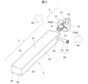
- the holder 1 of the present disclosure may have a rod shape extending from the first end 1a to the second end 1b along the reference axis O1, as shown in FIGS. 1 to 4.
- the reference axis O1 is an axis passing through the center of the holder 1.
- the first end 1a will be referred to as a front end 1a
- the second end 1b will be referred to as a rear end 1b.
- the holder 1 may include a first member 3 located closer to the tip 1a and a second member 5 located closer to the rear end 1b than the first member 3.
- the first member 3 may include a leading end 1a and the second member 5 may include a trailing end 1b.
- FIG. 1 is a plan view of the holder 1 viewed from above
- FIG. 2 is a perspective view of the holder 1 viewed from the A1 direction shown in FIG. 1
- FIG. 3 is a plan view of the holder 1 viewed from the A1 direction shown in FIG.
- FIG. 4 is a perspective view of the holder 1 shown in FIG. 3 viewed from the A2 direction, and shows a state in which the first member, the second member, and the fixture are disassembled. It is.
- the first member 3 has a first end surface 7 located on the front end 1a side, a second end surface 9 located on the rear end 1b side, and a first end surface 7 and a second end surface 9 located on the rear end 1b side.
- a first upper surface 11 located between the end surfaces 9, a first lower surface 13 located on the opposite side of the first upper surface 11, a first lateral surface 15 adjacent to the first upper surface 11, and a rear end from the second end surface 9. 1b, and a pocket 19 located on the tip 1a side and open at the first end surface 7, the first upper surface 11, and the first lateral surface 15.
- the first member 3 may have a second lateral surface 21 located on the opposite side to the first lateral surface 15.
- the first end surface 7, the first upper surface 11, the first lower surface 13, the first lateral surface 15, and the second lateral surface 21 may have a planar shape.
- the protrusion 17 may have a cylindrical shape extending along the central axis N3.
- the cylindrical shape does not necessarily have to be strictly cylindrical, and may have holes as shown in FIG.
- the second member 5 has a third end surface 23 located on the side of the tip 1a and facing the second end surface 9, and a hole 25 into which the protrusion 17 is inserted. and may have. Hole portion 25 extends along central axis N4. By inserting the protrusion 17 into the hole 25, the first member 3 is positioned relative to the second member 5. Note that in order to make it easier for the protrusion 17 to be inserted into the hole 25, the inner diameter of the hole 25 is slightly larger than the outer diameter of the protrusion 17, that is, there is some "play" between the hole 25 and the protrusion 17. may be set.
- the second member 5 has a second upper surface 27 located next to the third end surface 23, a second lower surface 29 located on the opposite side of the second upper surface 27, and a second upper surface 27. and a third lateral surface 31 located between the second lower surface 29, a fourth lateral surface 33 located on the opposite side of the third lateral surface 31, and a fourth end surface 34 located on the opposite side of the third end surface 23. , may have.
- the second upper surface 27, the second lower surface 29, the third lateral surface 31, the fourth lateral surface 33, and the fourth end surface 34 may each be flat.
- the second upper surface 27 is parallel to the second lower surface 29, and the third lateral surface 31 is parallel to the fourth lateral surface 33.
- a virtual straight line passes through the center of the fourth end surface 34 and is parallel to the second upper surface 27, the second lower surface 29, the third lateral surface 31, and the fourth lateral surface 33.
- the directions in which the second upper surface 27, the second lower surface 29, the third lateral surface 31, and the fourth lateral surface 33 face are the first upper surface 11, the first lower surface 13, and the first lower surface 13, respectively.
- the direction may be the same as the direction in which the first lateral surface 15 and the second lateral surface 21 face.
- the direction in which the first upper surface 11 faces is the upper side
- the direction in which the first lower surface 13 faces is the lower side
- the direction in which the first lateral surface 15 faces is referred to as the front side
- the direction in which the second lateral surface 21 faces Let be the backside.
- the second end surface 9 may have a first convex portion 35 that protrudes toward the rear end 1b.
- the first convex portion 35 may have a first tip surface 37 facing toward the rear end 1b and a first outer surface 39 connected to the first tip surface 37.
- the first tip surface 37 has a planar shape, and the first outer surface 39 may be located closer to the tip 1a than the first tip surface 37 is.
- 5 is a plan view of the first member 3 viewed from the rear end 1b side
- FIG. 7 is a plan view of the first member 3 viewed from the front side
- FIG. 9 is a plan view of the first member 3 viewed from the rear side.
- the third end surface 23 may have a first recess 41 recessed toward the rear end 1b.
- the first recess 41 may have a first bottom surface 43 facing the first tip surface 37 and a first inner surface 45 facing the first outer surface 39 .
- the first bottom surface 43 may have a planar shape and face the tip 1a, and the first inner surface 45 may be located closer to the tip 1a than the first bottom surface 43.
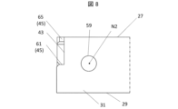
- 6 is a plan view of the second member 5 seen from the tip 1a side
- FIG. 8 is a plan view of the second member 5 seen from the front side
- FIG. 10 is a plan view of the second member 5 seen from the back side. This is a plan view.
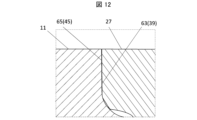
- FIGS. 11 and 12 are cross-sectional views of the holder 1 taken along the line XX in FIG. 1, etc.
- the XX cross section is a cross section that passes through the center portion of the first convex portion 35 in the direction in which the reference axis O1 extends and is perpendicular to the reference axis O1.
- FIG. 11 is an enlarged view corresponding to region B shown in FIGS. 5 and 6.
- FIG. 12 is an enlarged view corresponding to area C shown in FIGS. 5 and 6.
- the first outer surface 39 may have a first outer region 47 that faces the first lower surface 13 and has a convex curved surface that protrudes toward the first inner surface 45.
- the convex curved shape may be any convex curved shape that protrudes toward the first inner surface 45 in a cross section perpendicular to the reference axis O1, as shown in FIG.
- the first outer region 47 may be connected to the first lateral surface 15 .
- the entire downwardly facing surface of the first outer surface 39 may be composed of one first outer region 47 having a convex curve shape.
- the first inner surface 45 may have a first inner region 61 facing the first outer region 47.
- the first inner region 61 may face upward.
- the first outer region 47 may be in contact with the first inner region 61.
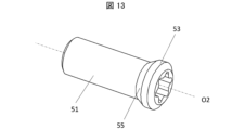
- the holder 1 of the present disclosure may include a fixture 49 that fixes the first member 3 to the second member 5, as shown in FIG.
- the fixture 49 has a shaft portion 51 extending along the fixture axis O2, a head portion 53 to be fixed, and a tapered portion 55 located between the shaft portion 51 and the head portion 53. You may.
- the tapered portion 55 may have a configuration in which the diameter gradually increases from the shaft portion 51 to the head portion 53.
- the protrusion 17 may have a first hole 57 into which the fixture 49 is inserted, and the second member 5 penetrates from the fourth lateral surface 33 to the hole 25. It may also have a second hole 59 into which the fixture 49 is inserted.
- 14 and 15 are diagrams showing the state of the holder 1 with the protrusion 17 of the first member 3 inserted into the hole 25 of the second member 5 and before the fixture 49 is inserted, respectively.
- . 14 is a plan perspective view of the first member 3 and the second member 5 seen from the front side
- FIG. 15 is a plan perspective view of the first member 3 and the second member 5 seen from the back side.
- the second hole 59 located on the back side may be larger than the head 53 of the fixture 49, and the head 53 may be larger than the first hole 57. Moreover, since the fixture 49 is inserted from the back side, the efficiency of the work of attaching the first member 3 to the second member 5 is improved. This also applies when the fixture 49 is inserted from the front side.
- the first member 3 rotates around the central axis N3 and the first outer region 47 is pressed against the first inner surface 45, so that the first member 3 is stabilized against the second member 5. is maintained.
- the rotating mechanism here is as follows.
- the fixture 49 is inserted into the second hole 59 and the first hole 57 from the back side, so that the tapered part 55 of the fixture 49 comes into contact with the upper part of the first hole 57. Furthermore, by tightening the fixture 49, the tapered portion 55 pushes the upper part of the first hole 57 from the back side to the front side, and as shown in FIG. When viewed toward the tip 1a, the first member 3 rotates slightly in the counterclockwise direction Y1 around the central axis N3.
- the first outer region 47 is pressed against the first inner surface 45 located below the first outer region 47, so that it is stably held.
- the fixture 49 when the fixture 49 is strongly tightened, the first outer region 47 may move slightly in the Y2 direction shown in FIG. 11 due to the play between the hole 25 and the protrusion 17.
- the first outer region 47 has a convex curved shape, the first member 3 is stably held by the second member 5 even if the first outer region 47 moves slightly.
- the fixture 49 may be inserted from the front side toward the back side, and in that case, the tapered portion 55 abuts the lower part of the first hole 57, and the first member 3 is aligned with the central axis N3. It may be rotated counterclockwise around the .
- the first member 3 is fixed to the second member 5 by tightening the fixture 49 at the same time as the above-mentioned insertion.
- the first member 3 may be fixed to the second member 5 by a fixing member different from the fixture 49 after the fixture 49 is inserted.
- the first protrusion 35 is connected to the first upper surface 11.
- the width W1 of the first convex portion 35 in the vertical direction shown in FIG. 5 can be made larger.
- the first convex portion 35 is located on the first upper surface 11 side on the second end surface 9.
- the first protrusion 35 being located closer to the first upper surface 11 means that the center of the first protrusion 35 is shorter than the distance from the center of the first protrusion 35 to the first lower surface 13 on the second end surface 9. This means that the distance from the first upper surface 11 to the first upper surface 11 is small.
- the width W2 of the second member 5 that receives the cutting load from the first convex portion 35 in the vertical direction the cutting load applied to the first member 3 is reduced. can be more stably received by the second member 5.
- the first inner region 61 may have a planar shape. In the example shown in FIG. 1 , the entire surface of the first inner surface 45 facing upward is the first inner region 61 . Further, the first inner region 61 may approach the second upper surface 27 as it approaches the third lateral surface 31. In the above case, the first outer region 47 is likely to move in the Y2 direction, and the first member 3 is likely to be stably held by the second member 5. Further, in the example shown in FIG. 6, the first inner region 61 is connected to the third lateral surface 31.
- the first outer region 47 may contact the first inner region 61 at the first contact point P1.
- the distance W3 from the first contact point P1 to the end S1 of the first outer region 47 on the side closer to the first lateral surface 15 is the distance W3 between the first contact point P1 may be smaller than the distance W4 from the first outer region 47 to the end S2 on the side away from the first lateral surface 15.
- the middle point of the contact portion may be set as the first contact point P1.
- the cutting edge 107 of the cutting insert 103 is located on the first lateral surface 15 side. Therefore, when the holder 1 has the above configuration, the cutting load can be stably received in the portion of the first outer region 47 on the side closer to the first lateral surface 15 where the cutting load is easily applied.
- the first outer region 47 may be located between the protrusion 17 and the first lateral surface 15 in the direction parallel to the first upper surface 11. In such a case, the cutting load can be stably received in a portion of the second end surface 9 closer to the first lateral surface 15, where the cutting load is likely to be applied.
- the first outer surface 39 may have a second outer region 63 facing opposite to the first lateral surface 15.
- the second outer region 63 faces the second lateral surface 21 side.
- the second outer region 63 may have a planar shape.
- the entire surface of the first outer surface 39 facing the back side may be the second outer region 63.
- the first inner surface 45 may have a second inner region 65 that faces the second outer region 63.
- the second inner region 65 faces the third lateral surface 31.
- the second inner region 65 may have a planar shape.
- the entire surface of the first inner surface 45 facing the front side may be the second inner region 65.
- the second outer region 63 may be in contact with the second inner region 65.
- the second outer region 63 may be in surface contact with the second inner region 65.
- surface contact does not require that the entire second outer region 63 be in contact with the entire second inner region 65, but that 1/5 or more of the entire second region should be in contact with the other region. That's enough.
- the second outer region 63 may move away from the second inner region 65 as it goes toward the first upper surface 11 from the contact point.
- the fixture 49 by inserting the fixture 49 into the second hole 59 and the first hole 57, the first outer region 47 moves in the Y2 direction shown in FIG. , and the second outer region 63 is pressed against the second inner region 65.
- the second member 5 can stably receive the cutting load.
- the first protrusion 35 is connected to the first lateral surface 15.
- the width W5 of the first convex portion 35 can be made larger.
- the first convex portion 35 is located on the side of the first lateral surface 15 on the second end surface 9.
- the first protrusion 35 being located on the side of the first lateral surface 15 means that the center of the first protrusion 35 is located on the side of the first lateral surface 15 in the second end surface 9. do.
- the width W6 of the second member 5 that receives the cutting load from the first convex portion 35 in the direction parallel to the first upper surface 11, , the cutting load applied to the first member 3 can be stably received by the second member 5.
- the second center axis N2 is the first center axis N1. It is located closer to the rear end 1b than the central axis N1. In such a case, when the fixture 49 is inserted, the first member 3 moves toward the rear end 1b. As a result, since the second end surface 9 is pressed against the third end surface 23, the accuracy of the position of the cutting edge of the cutting insert attached to the holder 1 is likely to be improved.
- the second central axis N2 may be located above the first central axis N1.
- the tapered part 55 comes into contact with the upper part of the first hole 57, and the first member 3 can be rotated slightly, making it easier for the first member 3 to be stably held by the second member 5.
- the positional relationship between the first central axis N1 and the second central axis N2 is such that the projection 17 of the first member 3 is inserted into the hole 25 of the second member 5, as shown in FIGS. 14 and 15. , shows the positional relationship immediately before the fixture 49 is inserted.
- the second end surface 9 may have a connecting portion 67 connected to the first outer surface 39 and located closer to the tip 1a than the first outer surface 39.
- the connecting portion 67 has a concave curved shape.
- it has a flat surface 69 that is connected to the connecting portion 67 and is located closer to the tip 1a than the connecting portion 67.
- the flat surface 69 faces toward the rear end 1b.
- the second end surface 9 may have a second convex portion 71 that protrudes toward the rear end 1b.
- the second convex portion 71 may be located on the lower side and on the back side of the second end surface 9.
- the second convex portion 71 may have a second tip surface 73 facing the rear end 1b and a second outer surface 75 connected to the second tip surface 73.
- the second outer surface 75 may have a third outer region 83 facing upward.
- the third end surface 23 may have a second recess 77 recessed toward the rear end 1b.
- the second recess 77 may have a second bottom surface 79 facing the second tip surface 73 and a second inner surface 81 facing the second outer surface 75 .
- the second bottom surface 79 faces toward the tip 1a.
- the second inner surface 81 may have a third inner region 85 facing the third outer region 83 .
- the third inner region 85 may face downward.
- the second tip surface 73, the second bottom surface 79, the third outer region 83, and the third inner region 85 may have a planar shape.
- a portion of the surface facing upward may be the third outer region 83 , or the entire surface facing upward may be the third outer region 83 .
- a portion of the surface facing downward may be the third inner region 85, or the entire surface facing downward may be the third inner region 85.
- the third outer region 83 is separated from the third inner region 85, but may be in contact with the third inner region 85.
- the third outer region 83 is separated from the first upper surface 11 as it approaches the second lateral surface 21.
- the length L1 of the first inner region 61 is smaller than the length L2 of the third inner region 85 in the direction parallel to the first upper surface 11. In such a case, since the configuration of the second end surface 9 becomes asymmetrical, it is possible to suppress the occurrence of a mistake in attaching the first member 3 to the second member 5.
- the second outer surface 75 has a fourth outer region 87 facing the front side
- the second inner surface 81 has a fourth inner region 89 facing the fourth outer region 87.
- the fourth inner region 89 may face the back side.
- the fourth outer region 87 and the fourth inner region 89 may have a planar shape.
- a portion of the surface facing the front side may be the fourth outer region 87, or the entire surface facing the front side may be the fourth outer region 87.
- a portion of the surface facing the back side may be the fourth inner region 89, or the entire surface facing the back side may be the fourth inner region 89.
- the fourth outer region 87 may be separated from the fourth inner region 89.
- the sizes of the first member 3 and the second member 5 are not particularly limited.
- the length from the tip 1a to the second end surface 9 may be 10 to 100 mm.
- the length from the first upper surface 11 to the first lower surface 13 may be 5 to 50 mm.
- the length from the third end surface 23 to the rear end 1b may be 50 to 200 mm.
- the length from the second upper surface 27 to the second lower surface 29 may be 5 to 50 mm.
- the length of the first convex portion in the vertical direction may be 2 to 18 mm.
- the length of the first convex portion in the direction parallel to the first upper surface may be 2 to 18 mm.
- the length of the second convex portion in the vertical direction may be 2 to 18 mm.
- the length of the second convex portion in the direction parallel to the first upper surface may be 2 to 18 mm.
- the material of the holder for example, steel, cast iron, cemented carbide, etc. can be used.
- the cutting tool 101 of the present disclosure has a rod shape extending from the tip 1a to the rear end 1b, as shown in FIGS. 16 to 18.
- the cutting tool 101 has a holder 1 and a cutting insert 103 located in a pocket 19 in the holder 1.
- the cutting insert 103 may have a through hole 105.
- the cutting tool 101 in the example shown in FIGS. 16 to 18 may include an insert screw 109 that can be used to secure the cutting insert 103 to the pocket 19.
- the pocket 19 may have a pocket hole 111 extending from the first upper surface 11 side toward the first lower surface 13 side.
- the cutting insert 103 can be fixed to the pocket 19 by inserting the insert screw 109 into the through hole 105 in the cutting insert 103 and the pocket hole 111 in the pocket 19 .
- Examples of the material of the cutting insert 103 include cemented carbide and cermet.
- Examples of the composition of the cemented carbide include WC-Co, WC-TiC-Co, and WC-TiC-TaC-Co.
- WC-Co is produced by adding cobalt (Co) powder to tungsten carbide (WC) and sintering it.
- WC-TiC-Co is WC-Co with titanium carbide (TiC) added.
- WC-TiC-TaC-Co is WC-TiC-Co with tantalum carbide (TaC) added.
- cermet is a sintered composite material in which a metal is combined with a ceramic component.
- the cermet includes a member containing a titanium compound such as titanium carbide (TiC) and titanium nitride (TiN) as a main component.
- the surface of cutting insert 103 may be coated with a film using chemical vapor deposition (CVD) or physical vapor deposition (PVD).
- CVD chemical vapor deposition
- PVD physical vapor deposition
- the composition of the film include titanium carbide (TiC), titanium nitride (TiN), titanium carbonitride (TiCN), and alumina (Al 2 O 3 ).
- a cut workpiece is produced by cutting a workpiece.
- the method for manufacturing a cut workpiece in the present disclosure includes the following steps. That is, (1) A step of rotating the work material 201; (2) a step of bringing the cutting tool 101 into contact with the rotating workpiece 201; (3) a step of separating the cutting tool 101 from the workpiece 201; It is equipped with
- the workpiece 201 is rotated around the rotation axis O3, and the cutting tool 101 is brought relatively close to the workpiece 201.
- the cutting blade 107 of the cutting tool 101 is brought into contact with the rotating workpiece 201 to cut the workpiece 201.
- the cutting tool 101 is moved relatively away from the workpiece 201.
- the cutting tool 101 is brought closer to the workpiece 201 by moving in the Y3 direction with the rotating shaft O3 fixed and the workpiece 201 being rotated. Further, in FIG. 17, the rotating workpiece 201 is cut by bringing the cutting blade 107 of the insert into contact with the rotating workpiece 201. Further, in FIG. 18, the cutting tool 101 is moved away from the workpiece 201 by moving it in the Y4 direction while the workpiece 201 is being rotated.
- the cutting tool 101 in each step, is brought into contact with the work material 201 by moving the cutting tool 101, or the cutting tool 101 is separated from the work material 201.
- the cutting tool 101 in each step, it is of course not limited to this form.
- the workpiece 201 may be brought closer to the cutting tool 101.
- the workpiece 201 may be moved away from the cutting tool 101.
- examples of the material of the work material 201 include carbon steel, alloy steel, stainless steel, cast iron, and non-ferrous metals.
- a rod-shaped holder extending from a first end to a second end along a reference axis includes a first member located closer to the first end, and a rod-shaped holder that extends from the first end to the second end; a second member located on the second end side; the first member has a first end face located on the first end side; and a second end face located on the second end side. , a first upper surface located between the first end surface and the second end surface, a first lower surface located on the opposite side of the first upper surface, and a first lower surface located between the first upper surface and the first lower surface.
- the second member has a third end surface located on the first end side and opposite to the second end surface, and into which the protrusion is inserted.
- the second end surface has a first convex portion extending toward the second end side, and the first convex portion has a first convex portion extending toward the second end side; a first end surface, and a first outer surface connected to the first end surface, the third end surface has a first recess depressed toward the second end, and the third end surface has a first recess depressed toward the second end; has a first bottom surface facing the first tip surface, and a first inner surface facing the first outer surface, the first outer surface facing the first lower surface, and , the first outer region may have a convex curved shape protruding toward the first inner surface, and the first inner surface may have a first inner region in contact with the first outer region.
- the first convex portion may be located on the first upper surface side in the second end surface.
- the first inner region may have a planar shape.
- the first outer region is located between the protrusion and the first lateral surface in a direction parallel to the first upper surface. Good too.
- the first outer surface further includes a second outer region having a planar shape facing opposite to the first lateral surface
- the first inner surface may further include a second inner region having a planar shape opposite to the second outer region.
- the second outer region may be in surface contact with the second inner region.
- the hole has a second hole into which the fixture is inserted, and the center axis of the second hole is closer to the second end than the center axis of the first hole. and may be located on the side of the first upper surface.
- the second end surface is connected to the first outer surface, and the recess is located closer to the first end than the first outer surface.
- a curved first connecting portion and a flat surface connected to the first connecting portion, located closer to the first end than the first connecting portion, and facing toward the second end. It's okay.
- the second end surface further includes a second convex portion protruding toward the second end side, and the second convex portion is , a second end surface facing toward the second end, and a second outer surface connected to the second end surface, and the third end surface is recessed toward the second end.
- the second recess further has a second tip surface that faces the second tip surface, and a second inner surface that faces the second outer surface.
- the side surface has a third outer region that faces the first upper surface and is separated from the second inner surface, and the second inner surface has the planar shape facing the third outer region. It has a third inner region, and the length of the second inner region is smaller than the length of the third inner region in a direction parallel to the first upper surface.
- a cutting tool may include the holder of any one of (1) to (11) above and a cutting insert located in the pocket.
- a method for manufacturing a cut workpiece includes a step of rotating a workpiece, and a step of bringing one of the cutting tools of (13) into contact with the rotating workpiece, The method may further include a step of separating the cutting tool from the workpiece.
- Rotation axis Y1 ... Rotation direction Y2 ⁇ Y4 ... Movement direction W1 ⁇ W6... Width (distance) P1...First contact S1, S2...Ends N1 to N4...Central axis L1, L2...Length
Abstract
高い保持安定性を有するホルダが求められている。基準軸に沿って延びた棒形状であって、第1部材と、第2部材と、を有し、第1部材は、第1端面と、第2端面と、第1上面と、第1下面と、第1横面と、突起部と、ポケットと、を有し、第2部材は、第3端面と、穴部と、を有し、第2端面は、第1凸部を有し、第1凸部は、第1先端面と、第1外側面と、を有し、第3端面は、第1凹部を有し、第1凹部は、第1底面と、第1内側面と、を有し、第1外側面は、第1内側面に向かって突出した凸曲面形状の第1外領域を有し、第1内側面は、第1外領域と対向する第1内領域を有する。
Description
本開示は、ホルダ、切削工具及び切削加工物の製造方法に関し、より具体的には、2つの部材を有するホルダ、切削工具及び切削加工物の製造方法に関するものである。
被削材を切削加工する際に用いられる切削工具のホルダとして、例えば特許文献1に記載のホルダが知られている。特許文献1に記載の切削工具におけるホルダは、第1構成要素及び第2構成要素の2つの部材からなるホルダである。
本開示の一態様に基づくホルダは、基準軸に沿って第1端から第2端にかけて延びた棒形状であって、前記第1端の側に位置する第1部材と、該第1部材よりも前記第2端の側に位置する第2部材と、を有する。前記第1部材は、前記第1端の側に位置する第1端面と、前記第2端の側に位置する第2端面と、前記第1端面及び前記第2端面の間に位置する第1上面と、該第1上面の反対側に位置する第1下面と、前記第1上面及び前記第1下面の間に位置する第1横面と、前記第2端面から前記第2端の側に向かって延びた突起部と、前記第1端の側に位置して、前記第1端面、前記第1上面及び前記第1横面にかけて開口しているポケットと、を有する。前記第2部材は、前記第1端の側に位置して、前記第2端面に対向している第3端面と、前記突起部が挿入される穴部と、を有する。前記第2端面は、前記第2端の側に向かって延びる第1凸部を有する。前記第1凸部は、前記第2端の側を向く第1先端面と、該第1先端面に接続される第1外側面と、を有し、前記第3端面は、前記第2端に向かって窪んだ第1凹部を有する。前記第1凹部は、前記第1先端面と対向する第1底面と、前記第1外側面と対向する第1内側面と、を有する。前記第1外側面は、前記第1下面の側を向き、且つ、前記第1内側面に向かって突出した凸曲面形状の第1外領域を有する。前記第1内側面は、前記第1外領域と当接する第1内領域を有する。
ホルダが複数の部材によって構成されている場合に、これらの部材の間での結合の安定性を向上することが求められている。
本開示によれば、上記のホルダは、高い保持安定性を有する。
以下、実施形態のホルダ1について、それぞれ図面を用いて詳細に説明する。但し、以下で参照する各図は、説明の便宜上、各実施形態を説明する上で必要な主要部材のみを簡略化して示したものである。したがって、本開示のホルダ1は、参照する各図に示されていない任意の構成部材を備え得る。また、各図中の部材の寸法は、実際の構成部材の寸法及び各部材の寸法比率等を忠実に表したものではない。
本開示のホルダ1は、図1~4に示すように、基準軸O1に沿って第1端1aから第2端1bにかけて延びた棒形状であってもよい。基準軸O1はホルダ1の中心を通る軸である。以下、説明の便宜上、第1端1aを先端(frond end)1a、第2端1bを後端(rear end)1bとする。ホルダ1は、先端1aの側に位置する第1部材3と、第1部材3よりも後端1bの側に位置する第2部材5と、を有してもよい。図1~4に示す限定されない一例においては、第1部材3が先端1aを含み、第2部材5が後端1bを含んでもよい。
なお、図1は、ホルダ1を上面視した平面図、図2は、ホルダ1を図1に示すA1方向から見た斜視図、図3は、図2に示す第1部材3を第2部材5から離した状態を示す斜視図、図4は、図3に示すホルダ1をA2方向から見た斜視図であって、第1部材、第2部材及び固定具が分解された状態を示す図である。
図3及び図4に示すように、第1部材3は、先端1aの側に位置する第1端面7と、後端1bの側に位置する第2端面9と、第1端面7及び第2端面9の間に位置する第1上面11と、第1上面11の反対側に位置する第1下面13と、第1上面11と隣り合う第1横面15と、第2端面9から後端1bの側に向かって延びる突起部17と、先端1aの側に位置して、第1端面7、第1上面11及び第1横面15において開口しているポケット19と、を有してもよい。また、図4に示す一例において、第1部材3は、第1横面15と反対側に位置する第2横面21を有してもよい。
第1端面7、第1上面11、第1下面13、第1横面15及び第2横面21は、平面形状であってもよい。また、突起部17は、中心軸N3に沿って延びた円柱形状であってもよい。ここで、円柱形状とは、厳密に円柱である必要はなく、図4に示すように、穴が開いていてもよい。
図3及び図4に示すように、第2部材5は、先端1aの側に位置して、第2端面9に対向している第3端面23と、突起部17が挿入される穴部25と、を有してもよい。穴部25は、中心軸N4に沿って延びている。突起部17が穴部25に挿入されることによって、第2部材5に対する第1部材3の位置決めが図られる。なお、突起部17が穴部25に挿入されやすくするため、穴部25の内径が突起部17の外径よりも若干大きい、すなわち、穴部25及び突起部17の間に若干の「遊び」が設定されてもよい。
また、図4に示す一例において、第2部材5は、第3端面23の隣に位置する第2上面27と、第2上面27の反対側に位置する第2下面29と、第2上面27と第2下面29の間に位置する第3横面31と、第3横面31の反対側に位置する第4横面33と、第3端面23の反対側に位置する第4端面34と、を有してもよい。
図3及び図4に示す限定されない一例のように、第2上面27、第2下面29、第3横面31、第4横面33及び第4端面34がそれぞれ平らであってもよい。このとき、図3及び図4に示す一例においては、第2上面27は、第2下面29に対して平行であり、第3横面31は、第4横面33に対して平行であってもよい。また、このとき、図1に示す一例において、第4端面34の中心を通り、第2上面27、第2下面29、第3横面31及び第4横面33に対して平行な仮想直線が、基準軸O1であってもよい。
ここで、図1~4に示す一例においては、第2上面27、第2下面29、第3横面31及び第4横面33の向く方向は、それぞれ第1上面11、第1下面13、第1横面15及び第2横面21の向く方向と同じであってもよい。以下、説明の便宜上、第1上面11が向く方向を上側、第1下面13が向く方向を下側、第1横面15が向く方向を正面側(foreside)、第2横面21が向く方向を背面側(backside)とする。
図4、図5、図7及び図9に示すように、第2端面9は、後端1bの側に向かって突出した第1凸部35を有してもよい。第1凸部35は、後端1bの側を向く第1先端面37及び第1先端面37に接続される第1外側面39を有してもよい。図7に示す一例において、第1先端面37は、平面形状であって、第1外側面39は、第1先端面37よりも先端1aの側に位置してもよい。なお、図5は、第1部材3を後端1bの側から見た平面図、図7は、第1部材3を正面側から見た平面図、図9は、第1部材3を背面側から見た平面図である。
図3、図6、図8及び図10に示すように、第3端面23は、後端1bの側に窪んだ第1凹部41を有してもよい。第1凹部41は、第1先端面37と対向する第1底面43と、第1外側面39と対向する第1内側面45を有してもよい。第1底面43は、平面形状であって、先端1aの側を向いてもよく、第1内側面45は、第1底面43より先端1aの側に位置してもよい。なお、図6は、第2部材5を先端1aの側から見た平面図、図8は、第2部材5を正面側から見た平面図、図10は、第2部材5を背面側から見た平面図である。
ここで、図11及び図12は、図1等におけるX-X線におけるホルダ1の断面図である。X-X断面は、基準軸O1が延びる方向における第1凸部35の中央部分を通り、且つ、基準軸O1に垂直な断面である。図11は、図5及び図6に示す領域Bに相当する拡大図である。図12は、図5及び図6に示す領域Cに相当する拡大図である。
第1外側面39は、第1下面13の側を向き、且つ、第1内側面45に向かって突出した凸曲面形状の第1外領域47を有してもよい。ここで、凸曲面形状とは、図11に示すように、基準軸O1に直交する断面において、第1内側面45に向かって突出した凸曲線形状であればよい。図5に示す一例において、第1外領域47は、第1横面15と接続してもよい。
また、図11に示す一例においては、第1外側面39のうち、下側を向いている面全体が、1つの凸曲線形状の第1外領域47から構成されてもよい。
第1内側面45は、第1外領域47と対向する第1内領域61を有してもよい。図8に示す一例において、第1内領域61は上側を向いてもよい。図11に示す一例において、第1外領域47は、第1内領域61と当接してもよい。
本開示のホルダ1は、図4に示すように、第1部材3を第2部材5に固定する固定具49を有してもよい。図13に示す一例においては、固定具49は、固定具軸O2に沿って延びる軸部51、固定される頭部53及び軸部51と頭部53との間に位置するテーパ部55を有してもよい。図13に示す一例において、テーパ部55は、軸部51から頭部53にかけて径が次第に大きくなる構成であってもよい。
図14及び図15に示す一例において、突起部17は、固定具49が挿入される第1穴57を有してもよく、第2部材5は、第4横面33から穴部25まで貫通してもよく、且つ、固定具49が挿入される第2穴59を有してもよい。図14及び図15は、それぞれ第1部材3の突起部17を第2部材5の穴部25に挿入した状態であって、固定具49を挿入する前のホルダ1の状態を示す図である。図14は、第1部材3及び第2部材5を正面側から透視した平面透視図、図15は、第1部材3及び第2部材5を背面側から透視した平面透視図である。
本開示のホルダ1において、背面側に位置する第2穴59は、固定具49の頭部53よりも大きくてもよく、頭部53は、第1穴57よりも大きくてもよい。また、固定具49は、背面側から挿入されるため、第1部材3を第2部材5に取り付ける作業の効率が良くなる。これは、固定具49が正面側から挿入された場合も同様である。
本開示のホルダ1は、第1部材3が中心軸N3の周りで回転し、第1外領域47が第1内側面45に押し付けられることにより、第1部材3が第2部材5に安定して保持される。ここで回転する機構は下記の通りである。
まず、固定具49が背面側から第2穴59及び第1穴57に挿入されることにより、固定具49のテーパ部55が第1穴57の上側の部分に当接する。さらに、固定具49が締め付けられることによって、テーパ部55が第1穴57の上側の部分を背面側から正面側に押し込み、図5に示すように、第1部材3を後端1bの側から先端1aの側に向かって見た場合において、第1部材3は、中心軸N3の周りで反時計周りの方向Y1に僅かに回転する。
そして、上記の回転により、第1外領域47が、その下側に位置する第1内側面45に押し付けられることで、安定して保持されることとなる。その結果、切削加工時において、第1部材3に大きな切削負荷が加わった場合であっても、第1部材3と第2部材5とのズレが生じることを抑制し、安定した切削加工を行うことができる。ここで、固定具49を強く締め付けた際に、穴部25及び突起部17の間の遊びに起因して、第1外領域47が、図11に示すY2方向に僅かに移動し得る。第1外領域47が凸曲面形状である場合には、第1外領域47が僅かに移動したとしても、第1部材3が第2部材5により安定して保持される。
なお、上記の機構はあくまで一例であり、上記の機構に限定されない。例えば、固定具49が正面側から背面側に向かって挿入されてもよく、その場合には、テーパ部55が第1穴57の下側の部分に当接し、第1部材3を中心軸N3の周りで反時計周りに回転させるものであってもよい。
また、本開示のホルダ1においては、固定具49がネジであるため、上記の挿入と同時に、固定具49が締め付けられることにより、第1部材3が第2部材5に固定されるが、固定具49が挿入された後に、固定具49とは別の固定部材により、第1部材3が第2部材5に固定される機構であってもよい。
図5に示す一例においては、第1凸部35が第1上面11と接続している。このような場合には、図5に示す上下方向における第1凸部35の幅W1をより大きくすることができる。
図5に示す一例において、第1凸部35は、第2端面9において、第1上面11の側に位置している。ここで、第1凸部35が第1上面11の側に位置するとは、第2端面9において、第1凸部35の中心から第1下面13までの距離よりも第1凸部35の中心から第1上面11までの距離が小さい場合を意味する。このような場合には、図6に示すように、上下方向における、第1凸部35から切削負荷を受ける第2部材5の幅W2が確保されることにより、第1部材3にかかる切削負荷を第2部材5でより安定して受けることができる。
第1内領域61は平面形状であってもよい。図1に示す一例においては、第1内側面45のうち、上側を向く面全体が第1内領域61である。また、第1内領域61は、第3横面31に近づくにつれて、第2上面27に近づいてもよい。上記の場合には、第1外領域47がY2方向に移動しやすくなり、第1部材3が第2部材5に安定して保持されやすい。また、図6に示す一例において、第1内領域61は、第3横面31と接続している。
図11に示す一例において、第1外領域47は、第1接点P1において第1内領域61と接してもよい。図11に示すように、第1上面11と平行な方向において、第1接点P1から第1外領域47における第1横面15に近い側の端部S1までの間隔W3は、第1接点P1から第1外領域47における第1横面15から離れた側の端部S2までの間隔W4よりも小さくてもよい。なお、第1外領域47が第1内領域61と面で接触しており、第1接点P1が1点では特定できない場合は、接触部分の中点を第1接点P1としてよい。
本開示のホルダ1のポケット19に切削インサート103が取り付けられた場合には、切削インサート103の切刃107は第1横面15の側に位置する。したがって、ホルダ1が上記の構成を有する場合には、切削負荷のかかりやすい、第1外領域47における第1横面15に近い側の部分において切削負荷を安定して受け止めることができる。
図5に示すように、第1上面11と平行な方向において、第1外領域47は突起部17と第1横面15の間に位置してもよい。このような場合には、切削負荷のかかりやすい、第2端面9における第1横面15に近い側の部分において切削負荷を安定して受け止めることができる。
図5及び図12に示す一例において、第1外側面39は、第1横面15の反対側を向いている第2外領域63を有してもよい。第2外領域63は、第2横面21の側を向いていると言い換えてもよい。また、第2外領域63は、平面形状であってもよい。図5及び図12に示す一例において、第1外側面39のうち、背面側を向く面全体が第2外領域63であってもよい。
図6及び図12に示す一例において、第1内側面45は、第2外領域63に対向する第2内領域65を有してもよい。図6及び図12に示す一例において、第2内領域65は、第3横面31の側を向いている。また、第2内領域65は、平面形状であってもよい。図6及び図12に示す一例において、第1内側面45のうち、正面側を向く面全体が第2内領域65であってもよい。
図12に示す一例において、第2外領域63は、第2内領域65と接してもよい。図12に示す一例において、第2外領域63は、第2内領域65と面接触してもよい。ここで、面接触とは、第2外領域63の全体が第2内領域65の全体に接している必要はなく、一方の領域の全体の1/5以上が、他方の領域に接していれば足りる。第2外領域63は、第2内領域65と接している場合、その接点から第1上面11の側に向かうにしたがって、第2外領域63は、第2内領域65から離れてもよい。
ここで、固定具49が第2穴59及び第1穴57に挿入されることにより、第1外領域47が図5に示すY2方向に移動するため、第1凸部35の全体が背面方向に移動し、第2外領域63が第2内領域65に押し付けられる。その結果、第1部材3に背面方向の切削負荷がかかった際に、第2部材5で安定して受け止めることができる。
図5に示す一例においては、第1凸部35が第1横面15と接続している。このような場合には、第1凸部35の幅W5をより大きくすることができる。
図5に示す一例において、第1凸部35は、第2端面9において、第1横面15の側に位置している。ここで、第1凸部35が第1横面15の側に位置するとは、第1凸部35の中心が第2端面9において、第1横面15の側に位置していることを意味する。このような場合には、図5及び図6に示すように、第1上面11に平行な方向における、第1凸部35から切削負荷を受ける第2部材5の幅W6が確保されることにより、第1部材3にかかる切削負荷を第2部材5で安定して受けることができる。
図14及び図15に示す一例において、第1穴57の中心軸を第1中心軸N1、第2穴59の中心軸を第2中心軸N2としたとき、第2中心軸N2は、第1中心軸N1よりも後端1bの側に位置している。このような場合には、固定具49が挿入された際に、第1部材3が後端1bの側に移動する。その結果、第2端面9が第3端面23に押し付けられるため、ホルダ1に取り付けられる切削インサートの刃先位置の精度が向上しやすい。
また、図14及び図15に示すように、第2中心軸N2は、第1中心軸N1よりも上側に位置してもよい。第2中心軸N2が第1中心軸N1よりも上側に位置する場合には、固定具49が挿入された際に、テーパ部55が第1穴57の上側の部分に当接し、第1部材3を僅かに回転させることができ、第1部材3が第2部材5に安定して保持されやすくなる。
なお、上記の第1中心軸N1と第2中心軸N2の位置関係は、図14及び図15に示すように、第1部材3の突起部17が第2部材5の穴部25に挿入され、固定具49が挿入される直前における位置関係を示している。
図5に示す一例において、後端1bの側から第1部材3を見た場合において、突起部17の中心軸N3は基準軸O1から離れている。図6に示す一例において、先端1aの側から第2部材5を見た場合において、穴部25の中心軸N4は基準軸O1から離れている。このような場合には、突起部17が第1部材3の中心に位置していないため、第1部材3を第2部材5に取り付ける際に、第1部材3を第2部材5に上下反対にして取り付けてしまう等のミスの発生を抑制することができる。
図5及び図7に示す一例において、第2端面9は、第1外側面39に接続され、第1外側面39よりも先端1aの側に位置する接続部67を有してもよい。図7に示す一例において、接続部67は、凹曲面形状である。図5及び図7に示す一例において、接続部67に接続され、接続部67よりも先端1aの側に位置する平坦面69を有している。図7に示す一例において、平坦面69は、後端1bの側を向いている。第2端面9が凹曲面形状の接続部67を有する場合には、第1部材3が第2部材5に取り付けられた際に、第3端面23における接続部67と対向する部分の欠けが生じにくくなる。
第2端面9は、後端1bの側に向かって突出する第2凸部71を有してもよい。図5に示す一例において、第2凸部71は、第2端面9において、下側、且つ、背面側に位置してもよい。図5に示す一例において、第2凸部71は、後端1bの側を向く第2先端面73及び第2先端面73に接続される第2外側面75を有してもよい。図9に示す一例において、第2外側面75は、上側を向いている第3外領域83を有してもよい。
第3端面23は、後端1bの側に向かって窪んだ第2凹部77を有してもよい。図6に示す一例において、第2凹部77は、第2先端面73と対向する第2底面79と、第2外側面75と対向する第2内側面81を有してもよい。図10に示す一例において、第2底面79は、先端1aの側を向いている。図6に示す一例において、第2内側面81は、第3外領域83と対向する第3内領域85を有してもよい。図10に示す一例において、第3内領域85は、下側を向いてもよい。
本開示のホルダ1において、第2先端面73、第2底面79、第3外領域83及び第3内領域85は、平面形状であってもよい。第2外側面75のうち、上側を向く面の一部が第3外領域83であってもよく、上側を向く面全体が第3外領域83であってもよい。また、第2内側面81のうち、下側を向く面の一部が第3内領域85であってもよく、下側を向く面全体が第3内領域85であってもよい。
本開示のホルダ1において、第3外領域83は、第3内領域85と離れているが、接してもよい。本開示のホルダ1において、第3外領域83は、第2横面21に近づくにつれて、第1上面11から離れている。図6に示す一例において、第1上面11と平行な方向において、第1内領域61の長さL1は、第3内領域85の長さL2よりも小さい。このような場合には、第2端面9の構成が非対称となるため、第1部材3を第2部材5に取り付けミスの発生を抑制することができる。
図5に示す一例において、第2外側面75は、正面側を向く第4外領域87を有し、第2内側面81は、第4外領域87と対向する第4内領域89を有してもよく、また、第4内領域89は、背面側を向いてもよい。図5に示す一例において、第4外領域87及び第4内領域89は、平面形状であってもよい。第2外側面75のうち、正面側を向く面の一部が第4外領域87であってもよく、正面側を向く面全体が第4外領域87であってもよい。第2内側面81のうち、背面側を向く面の一部が第4内領域89であってもよく、背面側を向く面全体が第4内領域89であってもよい。本開示のホルダ1において、第4外領域87は、第4内領域89と離れてもよい。
第1部材3及び第2部材5の大きさは特に限定されない。例えば、先端1aから第2端面9までの長さは10~100mmであってもよい。また、第1上面11から第1下面13までの長さは、5~50mmであってもよい。また、第3端面23から後端1bまでの長さは50~200mmであってもよい。また、第2上面27から第2下面29までの長さは、5~50mmであってもよい。
また、上下方向における第1凸部の長さは、2~18mmであってもよい。第1上面に平行な方向における第1凸部の長さは、2~18mmであってもよい。上下方向における第2凸部の長さは、2~18mmであってもよい。第1上面に平行な方向における第2凸部の長さは、2~18mmであってもよい。
ホルダ1の材質としては、例えば、鋼、鋳鉄、超硬合金などを用いることができる。
<切削工具>
次に、本開示の実施形態の切削工具について図面を用いて説明する。
次に、本開示の実施形態の切削工具について図面を用いて説明する。
本開示の切削工具101は、図16~図18に示すように、先端1aから後端1bにかけて延びた棒形状である。切削工具101は、ホルダ1と、ホルダ1におけるポケット19に位置する切削インサート103と、を有する。切削インサート103は、貫通穴105を有してもよい。
図16~図18に示す一例における切削工具101は、切削インサート103をポケット19に固定する際に用いることが可能なインサートねじ109を備えてもよい。ポケット19は、図1に示す一例において、第1上面11の側から第1下面13の側に向かって延びたポケット穴111を有していてもよい。インサートねじ109を切削インサート103における貫通穴105及びポケット19におけるポケット穴111に挿入することによって、切削インサート103をポケット19に固定することが可能である。
切削インサート103の材料としては、例えば、超硬合金及びサーメットなどが挙げられる。超硬合金の組成としては、例えば、WC-Co、WC-TiC-Co及びWC-TiC-TaC-Coが挙げられる。WC-Coは、炭化タングステン(WC)にコバルト(Co)の粉末を加えて焼結して生成される。WC-TiC-Coは、WC-Coに炭化チタン(TiC)を添加したものである。WC-TiC-TaC-Coは、WC-TiC-Coに炭化タンタル(TaC)を添加したものである。
また、サーメットは、セラミック成分に金属を複合させた焼結複合材料である。具体的には、サーメットとして、炭化チタン(TiC)及び窒化チタン(TiN)などのようなチタン化合物を主成分として含有する部材が挙げられる。
切削インサート103の表面は、化学蒸着(CVD)法又は物理蒸着(PVD)法を用いて被膜でコーティングされていてもよい。被膜の組成としては、炭化チタン(TiC)、窒化チタン(TiN)、炭窒化チタン(TiCN)及びアルミナ(Al2O3)などが挙げられる。
<切削加工物の製造方法>
次に、本開示の実施形態の切削加工物の製造方法について図面を用いて説明する。
次に、本開示の実施形態の切削加工物の製造方法について図面を用いて説明する。
切削加工物は、被削材を切削加工することによって作製される。本開示における切削加工物の製造方法は、以下の工程を備えている。すなわち、
(1)被削材201を回転させる工程と、
(2)回転している被削材201に切削工具101を接触させる工程と、
(3)切削工具101を被削材201から離す工程と、
を備えている。
(1)被削材201を回転させる工程と、
(2)回転している被削材201に切削工具101を接触させる工程と、
(3)切削工具101を被削材201から離す工程と、
を備えている。
より具体的には、まず、図16に示すように、被削材201を回転軸O3の周りで回転させるとともに、被削材201に切削工具101を相対的に近づける。次に、図17に示すように、切削工具101における切刃107を回転している被削材201に接触させて、被削材201を切削する。そして、図18に示すように、切削工具101を被削材201から相対的に遠ざける。
実施形態においては、回転軸O3を固定するとともに被削材201を回転させた状態で切削工具101をY3方向に移動させることによって被削材201に近づけている。また、図17においては、回転している被削材201にインサートにおける切刃107を接触させることによって被削材201を切削している。また、図18においては、被削材201を回転させた状態で切削工具101をY4方向に移動させることによって遠ざけている。
なお、実施形態の製造方法における切削加工では、それぞれの工程において、切削工具101を動かすことによって、切削工具101を被削材201に接触させる、或いは、切削工具101を被削材201から離しているが、当然ながらこのような形態に限定されるものではない。
例えば、(1)の工程において、被削材201を切削工具101に近づけてもよい。同様に、(3)の工程において、被削材201を切削工具101から遠ざけてもよい。切削加工を継続する場合には、被削材201を回転させた状態を維持して、被削材201の異なる箇所にインサートにおける切刃107を接触させる工程を繰り返せばよい。
なお、被削材201の材質としては、例えば、炭素鋼、合金鋼、ステンレス、鋳鉄、又は非鉄金属などが挙げられる。
一実施形態において、(1) 基準軸に沿って第1端から第2端にかけて延びた棒形状のホルダは、前記第1端の側に位置する第1部材と、該第1部材よりも前記第2端の側に位置する第2部材と、を有し、前記第1部材は、前記第1端の側に位置する第1端面と、前記第2端の側に位置する第2端面と、前記第1端面及び前記第2端面の間に位置する第1上面と、該第1上面の反対側に位置する第1下面と、前記第1上面及び前記第1下面の間に位置する第1横面と、前記第2端面から前記第2端の側に向かって延びた突起部と、前記第1端の側に位置して、前記第1端面、前記第1上面及び前記第1横面にかけて開口しているポケットと、を有し、前記第2部材は、前記第1端の側に位置して、前記第2端面に対向している第3端面と、前記突起部が挿入された穴部と、を有し、前記第2端面は、前記第2端の側に向かって延びた第1凸部を有し、前記第1凸部は、前記第2端の側を向く第1先端面と、該第1先端面に接続される第1外側面と、を有し、前記第3端面は、前記第2端に向かって窪んだ第1凹部を有し、前記第1凹部は、前記第1先端面と対向する第1底面と、前記第1外側面と対向する第1内側面と、を有し、前記第1外側面は、前記第1下面の側を向き、且つ、前記第1内側面に向かって突出した凸曲面形状の第1外領域を有し、前記第1内側面は、前記第1外領域と当接する第1内領域を有してもよい。
(2)上記(1)のホルダにおいて、前記第1凸部は、第2端面において、第1上面の側に位置してもよい。
(3)上記(1)又は(2)のホルダにおいて、前記第1内領域は、平面形状であってもよい。
(4)上記(1)から(3)のいずれかのホルダにおいて、前記第1外領域と前記第1内領域との接点を第1接点としたとき、前記第1上面と平行な方向において、前記第1接点から前記第1外領域における前記第1横面に近い側の端部までの間隔は、前記第1接点から前記第1外領域における前記第1横面から離れた側の端部までの間隔よりも小さくてもよい。
(5)上記(1)から(4)のいずれかのホルダにおいて、前記第1上面と平行な方向において、前記第1外領域は、前記突起部と前記第1横面の間に位置してもよい。
(6)上記(1)から(5)のいずれかのホルダにおいて、前記第1外側面は、前記第1横面の反対側を向いている平面形状の第2外領域をさらに有し、前記第1内側面は、前記第2外領域に対向する平面形状の第2内領域をさらに有してもよい。
(7)上記(6)のホルダにおいて、前記第2外領域は、前記第2内領域と面接触してもよい。
(8)上記(1)から(7)のいずれかのホルダにおいて、前記第1部材を前記第2部材に固定する固定具を更に有し、前記突起部は、前記固定具が挿入される第1穴を有し、前記穴部は、前記固定具が挿入される第2穴を有し、前記第2穴の中心軸は、前記第1穴の中心軸よりも前記第2端の側に位置し、且つ、前記第1上面の側に位置してもよい。
(9)上記(1)から(8)のいずれかのホルダにおいて、前記第2端の側から前記第1部材を見た場合において、前記突起部の中心軸は、前記基準軸から離れてもよい。
(10)上記(1)から(9)のいずれかのホルダにおいて、前記第2端面は、前記第1外側面に接続され、前記第1外側面よりも前記第1端の側に位置する凹曲面形状の第1接続部と、該第1接続部に接続され、前記第1接続部よりも前記第1端の側に位置し、且つ、前記第2端の側を向く平坦面を有してもよい。
(11)上記(1)から(10)のいずれかのホルダにおいて、前記第2端面は、前記第2端の側に向かって突出する第2凸部をさらに有し、前記第2凸部は、前記第2端の側を向く第2先端面と、該第2先端面に接続される第2外側面と、有し、前記第3端面は、前記第2端の側に向かって窪んだ第2凹部をさらに有し、前記第2凹部は、前記第2先端面と対向する第2先端面と、前記第2外側面と対向する第2内側面と、を有し、前記第2外側面は、前記第1上面の側を向き、且つ、前記第2内側面と離れている第3外領域を有し、前記第2内側面は、前記第3外領域と対向する平面形状の前記第3内領域を有し、前記第1上面と平行な方向において、前記第2内領域の長さは、前記第3内領域の長さよりも小さい。
一実施形態において、(12)切削工具は、上記(1)~(11)のいずれかのホルダと、前記ポケットに位置する切削インサートと、を有してもよい。
一実施形態において、(13)切削加工物の製造方法は、被削材を回転させる工程と、回転している前記被削材に上記(13)のいずれかの切削工具を接触させる工程と、前記切削工具を前記被削材から離す工程と、を備えてもよい。
以上、本開示に係る実施形態について例示したが、本開示は上述した実施形態に限定されるものではなく、本開示の要旨を逸脱しない限り任意のものとすることができることはいうまでもない。
1・・・・ホルダ
1a・・・第1端(先端)
1b・・・第2端(後端)
3・・・・第1部材
5・・・・第2部材
7・・・・第1端面
9・・・・第2端面
11・・・第1上面
13・・・第1下面
15・・・第1横面
17・・・突起部
19・・・ポケット
21・・・第2横面
23・・・第3端面
25・・・穴部
27・・・第2上面
29・・・第2下面
31・・・第3横面
33・・・第4横面
34・・・第4端面
35・・・第1凸部
37・・・第1先端面
39・・・第1外側面
41・・・第1凹部
43・・・第1底面
45・・・第1内側面
47・・・第1外領域
49・・・固定具
51・・・軸部
53・・・頭部
55・・・テーパ部
57・・・第1穴
59・・・第2穴
61・・・第1内領域
63・・・第2外領域
65・・・第2内領域
67・・・接続部
69・・・平坦面
71・・・第2凸部
73・・・第2先端面
75・・・第2外側面
77・・・第2凹部
79・・・第2底面
81・・・第2内側面
83・・・第3外領域
85・・・第3内領域
87・・・第4外領域
89・・・第4内領域
101・・切削工具
103・・切削インサート
105・・貫通穴
107・・切刃
109・・インサートねじ
111・・ポケット穴
201・・被削材
O1・・・基準軸
O2・・・固定具軸
O3・・・回転軸
Y1・・・回転方向
Y2~Y4・・・移動方向
W1~W6・・・幅(間隔)
P1・・・第1接点
S1、S2・・・端部
N1~N4・・・中心軸
L1、L2・・・長さ
Claims (13)
- 基準軸に沿って第1端から第2端にかけて延びた棒形状であって、前記第1端の側に位置する第1部材と、該第1部材よりも前記第2端の側に位置する第2部材と、を有し、
前記第1部材は、
前記第1端の側に位置する第1端面と、
前記第2端の側に位置する第2端面と、
前記第1端面及び前記第2端面の間に位置する第1上面と、
該第1上面の反対側に位置する第1下面と、
前記第1上面及び前記第1下面の間に位置する第1横面と、
前記第2端面から前記第2端の側に向かって延びた突起部と、
前記第1端の側に位置して、前記第1端面、前記第1上面及び前記第1横面にかけて開口しているポケットと、を有し、
前記第2部材は、
前記第1端の側に位置して、前記第2端面に対向している第3端面と、
前記突起部が挿入された穴部と、を有し、
前記第2端面は、
前記第2端の側に向かって延びた第1凸部を有し、
前記第1凸部は、
前記第2端の側を向く第1先端面と、
該第1先端面に接続される第1外側面と、を有し、
前記第3端面は、
前記第2端に向かって窪んだ第1凹部を有し、
前記第1凹部は、
前記第1先端面と対向する第1底面と、
前記第1外側面と対向する第1内側面と、を有し、
前記第1外側面は、前記第1下面の側を向き、且つ、前記第1内側面に向かって突出した凸曲面形状の第1外領域を有し、
前記第1内側面は、前記第1外領域と当接する第1内領域を有する、ホルダ。 - 前記第1凸部は、第2端面において、第1上面の側に位置している、請求項1に記載のホルダ。
- 前記第1内領域は、平面形状である、請求項1又は2に記載のホルダ。
- 前記第1外領域と前記第1内領域との接点を第1接点としたとき、
前記第1上面と平行な方向において、前記第1接点から前記第1外領域における前記第1横面に近い側の端部までの間隔は、前記第1接点から前記第1外領域における前記第1横面から離れた側の端部までの間隔よりも小さい、請求項1~3のいずれか1項に記載のホルダ。 - 前記第1上面と平行な方向において、
前記第1外領域は、前記突起部と前記第1横面の間に位置する、請求項1~4のいずれか1項に記載のホルダ。 - 前記第1外側面は、
前記第1横面の反対側を向いている平面形状の第2外領域をさらに有し、
前記第1内側面は、
前記第2外領域に対向する平面形状の第2内領域をさらに有する、請求項1~5のいずれか1項に記載のホルダ。 - 前記第2外領域は、前記第2内領域と面接触する、請求項6に記載のホルダ。
- 前記第1部材を前記第2部材に固定する固定具を更に有し、
前記突起部は、前記固定具が挿入される第1穴を有し、
前記穴部は、前記固定具が挿入される第2穴を有し、
前記第2穴の中心軸は、前記第1穴の中心軸よりも前記第2端の側に位置し、且つ、前記第1上面の側に位置する、請求項1~7のいずれか1項に記載のホルダ。 - 前記第2端の側から前記第1部材を見た場合において、前記突起部の中心軸は、前記基準軸から離れている、請求項1~8のいずれか1項に記載のホルダ。
- 前記第2端面は、
前記第1外側面に接続され、前記第1外側面よりも前記第1端の側に位置する凹曲面形状の第1接続部と、
該第1接続部に接続され、前記第1接続部よりも前記第1端の側に位置し、且つ、前記第2端の側を向く平坦面を有する、請求項1~9のいずれか1項に記載のホルダ。 - 前記第2端面は、
前記第2端の側に向かって突出する第2凸部をさらに有し、
前記第2凸部は、
前記第2端の側を向く第2先端面と、
該第2先端面に接続される第2外側面と、有し
前記第3端面は、
前記第2端の側に向かって窪んだ第2凹部をさらに有し、
前記第2凹部は
前記第2先端面と対向する第2先端面と、
前記第2外側面と対向する第2内側面と、を有し、
前記第2外側面は、前記第1上面の側を向き、且つ、前記第2内側面と離れている第3外領域を有し、
前記第2内側面は、前記第3外領域と対向する平面形状の前記第3内領域を有し、
前記第1上面と平行な方向において、
前記第2内領域の長さは、前記第3内領域の長さよりも小さい、請求項1~10のいずれか1項に記載のホルダ。 - 請求項1~11のいずれか1項に記載のホルダと、
前記ポケットに位置する切削インサートと、を有する切削工具。 - 被削材を回転させる工程と、
回転している前記被削材に請求項12に記載の切削工具を接触させる工程と、
前記切削工具を前記被削材から離す工程と、を備えた切削加工物の製造方法。
Applications Claiming Priority (2)
| Application Number | Priority Date | Filing Date | Title |
|---|---|---|---|
| JP2022-118761 | 2022-07-26 | ||
| JP2022118761 | 2022-07-26 |
Publications (1)
| Publication Number | Publication Date |
|---|---|
| WO2024024488A1 true WO2024024488A1 (ja) | 2024-02-01 |
Family
ID=89706269
Family Applications (1)
| Application Number | Title | Priority Date | Filing Date |
|---|---|---|---|
| PCT/JP2023/025526 WO2024024488A1 (ja) | 2022-07-26 | 2023-07-11 | 切削工具及び切削加工物の製造方法 |
Country Status (1)
| Country | Link |
|---|---|
| WO (1) | WO2024024488A1 (ja) |
Citations (2)
| Publication number | Priority date | Publication date | Assignee | Title |
|---|---|---|---|---|
| JPH0550306A (ja) * | 1991-03-13 | 1993-03-02 | Mitsubishi Materials Corp | 切削工具 |
| JP2020028943A (ja) * | 2018-08-22 | 2020-02-27 | 京セラ株式会社 | ホルダ、切削工具及び切削加工物の製造方法 |
-
2023
- 2023-07-11 WO PCT/JP2023/025526 patent/WO2024024488A1/ja unknown
Patent Citations (2)
| Publication number | Priority date | Publication date | Assignee | Title |
|---|---|---|---|---|
| JPH0550306A (ja) * | 1991-03-13 | 1993-03-02 | Mitsubishi Materials Corp | 切削工具 |
| JP2020028943A (ja) * | 2018-08-22 | 2020-02-27 | 京セラ株式会社 | ホルダ、切削工具及び切削加工物の製造方法 |
Similar Documents
| Publication | Publication Date | Title |
|---|---|---|
| EP3213841B1 (en) | Cutting tool, and method for producing cut object | |
| US10384277B2 (en) | Tool body and cutting tool | |
| US11565328B2 (en) | Cutting insert, cutting tool, and method for manufacturing machined product | |
| JP7102283B2 (ja) | ホルダ、切削工具及び切削加工物の製造方法 | |
| JP7128185B2 (ja) | 切削インサート、切削工具及び切削加工物の製造方法 | |
| CN108698143B (zh) | 切削工具用刀具 | |
| WO2019039547A1 (ja) | インサート | |
| US10022810B2 (en) | Cutting tool and method for manufacturing machined product | |
| US10252341B2 (en) | Cutting insert, cutting tool, and method for manufacturing machined product | |
| WO2024024488A1 (ja) | 切削工具及び切削加工物の製造方法 | |
| WO2019107204A1 (ja) | 切削工具及び切削加工物の製造方法 | |
| JP5898028B2 (ja) | 切削工具および被削加工物の製造方法 | |
| JPWO2019065525A1 (ja) | 切削インサート、切削工具及び切削加工物の製造方法 | |
| JP7114733B2 (ja) | 切削インサート、切削工具及び切削加工物の製造方法 | |
| WO2023058588A1 (ja) | ホルダ、切削工具、及び切削加工物の製造方法 | |
| JP6711842B2 (ja) | 切削インサート、切削工具及び切削加工物の製造方法 | |
| JP7223773B2 (ja) | 回転工具及び切削加工物の製造方法 | |
| JPWO2020027171A1 (ja) | 切削工具及び切削加工物の製造方法 | |
| WO2023277181A1 (ja) | 切削インサート、切削工具及び切削加工物の製造方法 | |
| JP7344168B2 (ja) | 切削インサート、切削工具及び切削加工物の製造方法 | |
| CN111699066B (zh) | 切削刀片、切削工具以及切削加工物的制造方法 | |
| JP7117389B2 (ja) | 切削インサート、切削工具及び切削加工物の製造方法 | |
| WO2023277180A1 (ja) | ホルダ、切削工具及び切削加工物の製造方法 | |
| WO2021193705A1 (ja) | 回転工具及び切削加工物の製造方法 | |
| US20230415239A1 (en) | Cutting insert, cutting tool, and method for manufacturing machined product |
Legal Events
| Date | Code | Title | Description |
|---|---|---|---|
| 121 | Ep: the epo has been informed by wipo that ep was designated in this application |
Ref document number: 23846219 Country of ref document: EP Kind code of ref document: A1 |