WO2023058588A1 - Support, outil de découpe, et procédé de fabrication de pièce usinée - Google Patents
Support, outil de découpe, et procédé de fabrication de pièce usinée Download PDFInfo
- Publication number
- WO2023058588A1 WO2023058588A1 PCT/JP2022/036897 JP2022036897W WO2023058588A1 WO 2023058588 A1 WO2023058588 A1 WO 2023058588A1 JP 2022036897 W JP2022036897 W JP 2022036897W WO 2023058588 A1 WO2023058588 A1 WO 2023058588A1
- Authority
- WO
- WIPO (PCT)
- Prior art keywords
- region
- cutting
- holder
- stepped portion
- cutting tool
- Prior art date
Links
- 238000005520 cutting process Methods 0.000 title claims description 95
- 238000004519 manufacturing process Methods 0.000 title description 10
- 238000000034 method Methods 0.000 title description 8
- 239000000463 material Substances 0.000 claims description 27
- 238000003754 machining Methods 0.000 description 8
- QNRATNLHPGXHMA-XZHTYLCXSA-N (r)-(6-ethoxyquinolin-4-yl)-[(2s,4s,5r)-5-ethyl-1-azabicyclo[2.2.2]octan-2-yl]methanol;hydrochloride Chemical compound Cl.C([C@H]([C@H](C1)CC)C2)CN1[C@@H]2[C@H](O)C1=CC=NC2=CC=C(OCC)C=C21 QNRATNLHPGXHMA-XZHTYLCXSA-N 0.000 description 5
- MTPVUVINMAGMJL-UHFFFAOYSA-N trimethyl(1,1,2,2,2-pentafluoroethyl)silane Chemical compound C[Si](C)(C)C(F)(F)C(F)(F)F MTPVUVINMAGMJL-UHFFFAOYSA-N 0.000 description 5
- 229910052751 metal Inorganic materials 0.000 description 4
- 239000002184 metal Substances 0.000 description 4
- 239000011195 cermet Substances 0.000 description 3
- 238000010586 diagram Methods 0.000 description 3
- 238000009434 installation Methods 0.000 description 3
- 239000000203 mixture Substances 0.000 description 3
- 229910001018 Cast iron Inorganic materials 0.000 description 2
- 229910000831 Steel Inorganic materials 0.000 description 2
- NRTOMJZYCJJWKI-UHFFFAOYSA-N Titanium nitride Chemical compound [Ti]#N NRTOMJZYCJJWKI-UHFFFAOYSA-N 0.000 description 2
- 238000005229 chemical vapour deposition Methods 0.000 description 2
- 239000011248 coating agent Substances 0.000 description 2
- 238000000576 coating method Methods 0.000 description 2
- 238000005240 physical vapour deposition Methods 0.000 description 2
- 239000010959 steel Substances 0.000 description 2
- 229910018072 Al 2 O 3 Inorganic materials 0.000 description 1
- 229910000851 Alloy steel Inorganic materials 0.000 description 1
- 229910000975 Carbon steel Inorganic materials 0.000 description 1
- 229910000760 Hardened steel Inorganic materials 0.000 description 1
- 244000126211 Hericium coralloides Species 0.000 description 1
- RTAQQCXQSZGOHL-UHFFFAOYSA-N Titanium Chemical compound [Ti] RTAQQCXQSZGOHL-UHFFFAOYSA-N 0.000 description 1
- PNEYBMLMFCGWSK-UHFFFAOYSA-N aluminium oxide Inorganic materials [O-2].[O-2].[O-2].[Al+3].[Al+3] PNEYBMLMFCGWSK-UHFFFAOYSA-N 0.000 description 1
- 239000011230 binding agent Substances 0.000 description 1
- 239000010962 carbon steel Substances 0.000 description 1
- 239000000919 ceramic Substances 0.000 description 1
- 239000002131 composite material Substances 0.000 description 1
- 239000000470 constituent Substances 0.000 description 1
- 239000002173 cutting fluid Substances 0.000 description 1
- 230000006866 deterioration Effects 0.000 description 1
- 230000005489 elastic deformation Effects 0.000 description 1
- -1 ferrous metals Chemical class 0.000 description 1
- 150000002739 metals Chemical class 0.000 description 1
- 239000002245 particle Substances 0.000 description 1
- 230000000452 restraining effect Effects 0.000 description 1
- 230000000630 rising effect Effects 0.000 description 1
- 239000010935 stainless steel Substances 0.000 description 1
- 229910001220 stainless steel Inorganic materials 0.000 description 1
- 239000010936 titanium Substances 0.000 description 1
- 229910052719 titanium Inorganic materials 0.000 description 1
- 150000003609 titanium compounds Chemical class 0.000 description 1
Images


Classifications
-
- B—PERFORMING OPERATIONS; TRANSPORTING
- B23—MACHINE TOOLS; METAL-WORKING NOT OTHERWISE PROVIDED FOR
- B23B—TURNING; BORING
- B23B29/00—Holders for non-rotary cutting tools; Boring bars or boring heads; Accessories for tool holders
- B23B29/04—Tool holders for a single cutting tool
-
- B—PERFORMING OPERATIONS; TRANSPORTING
- B23—MACHINE TOOLS; METAL-WORKING NOT OTHERWISE PROVIDED FOR
- B23B—TURNING; BORING
- B23B29/00—Holders for non-rotary cutting tools; Boring bars or boring heads; Accessories for tool holders
- B23B29/24—Tool holders for a plurality of cutting tools, e.g. turrets
Definitions
- the present disclosure relates to a holder for a cutting tool used when cutting a work material such as metal, a cutting tool, and a method for manufacturing a cut product.
- the cutting tools described in Patent Documents 1 and 2 are known as cutting tools used for cutting work materials such as metals.
- the cutting tools described in Patent Documents 1 and 2 are used while attached to a tool post.
- a plate-like positioning member is attached to the tool body, and the rear end portion of the positioning member is brought into contact with the tool post.
- a positioning pin is attached to the main body, and the positioning pin abuts against the abutment surface of the tool post.
- JP 2011-245594 A Japanese Patent No. 6803014
- a non-limiting example holder in the present disclosure has a square prism shape extending from a first end toward a second end.
- the holder has a pocket located on the side of the first end and capable of mounting a cutting insert, a first side extending from the first end toward the second end, and an opposite side to the first side. a positioned second side.
- the second side has a flat first region located on the side of the first end, and a flat first region closer to the second end than the first region and closer to the first side than the first region. a flat second region positioned thereon; and a stepped portion connecting the first region and the second region.
- the step portion has a curved shape that protrudes toward the second end in a cross section parallel to the first region.
- FIG. 1 is a perspective view of a cutting tool in a non-limiting embodiment of the present disclosure
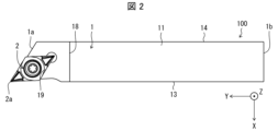
- FIG. FIG. 2 is a plan view of the cutting tool shown in FIG. 1
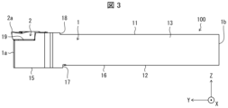
- FIG. 2 is a side view of the cutting tool shown in FIG. 1
- FIG. 2 is a rear view of the cutting tool shown in FIG. 1
- 4 is a partially enlarged view of the cutting tool shown in FIG. 3
- FIG. FIG. 6 is a cross-sectional view taken along the line VI-VI in FIG. 5
- 1 is a perspective view showing a cutting tool supported by a tool post in a non-limiting embodiment of the present disclosure
- FIG. Fig. 8 is a plan view of the cutting tool and the tool post shown in Fig. 7;
- FIG. 8 is a side view of the cutting tool and tool rest shown in FIG. 7;
- FIG. 10 is a partially enlarged view of the front portion of FIG. 9;
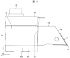
- FIG. 11 is an enlarged view of a reference example for the cutting tool shown in FIG. 10;
- 1 is a schematic diagram illustrating one step in a method for manufacturing a machined workpiece in one non-limiting example;
- FIG. 1 is a schematic diagram illustrating one step in a method for manufacturing a machined workpiece in one non-limiting example;
- FIG. 1 is a schematic diagram illustrating one step in a method for manufacturing a machined workpiece in one non-limiting example;
- FIG. 1 is a schematic diagram illustrating one step in a method for manufacturing a machined workpiece in one non-limiting example;
- Cutting tools include, for example, turning tools.
- Turning tools include, for example, grooving tools and parting off tools.
- the grooving tool can be used, for example, for grooving.
- the cutting tool 100 in one non-limiting example shown in FIG. 1 is a turning tool, and more specifically a grooving or stepping tool.
- the cutting tool 100 may comprise optional components not shown in the referenced figures.
- the dimensions of the members in each drawing do not necessarily represent the actual dimensions of the constituent members, the dimensional ratios of the respective members, and the like faithfully.
- the X-axis direction is the horizontal direction
- the Z-axis direction is the vertical direction
- the Y-axis direction is the front-back direction.
- the cutting insert 2 is located on the right side in the X-axis direction, the front side in the Y-axis direction, and the upper side in the Z-axis direction.
- the cutting insert 2 is simply referred to as "insert 2".
- a non-limiting example cutting tool 100 shown in FIGS. 1-6 includes a holder 1 , an insert 2 and a screw 3 .
- the holder 1 may be in the shape of a quadrangular prism extending from the first end 1a, which is the front end, toward the second end 1b, which is the rear end, along the first central axis L1.
- the front side of the holder 1 in the Y-axis direction is the first end 1a
- the rear side is the second end 1b.
- the size of the holder 1 is not particularly limited.
- the length in the direction along the first central axis L1 can be set to approximately 10 mm to 250 mm.
- the height from the top end to the bottom end, in other words, the width in the vertical direction of the Z-axis can be set to about 5 mm to 50 mm.
- Steel, cast iron, or the like may be used as the member of the holder 1 .
- the toughness of the holder 1 is high.
- the holder 1 has a first side surface 11 extending upward in the Z-axis direction from a first end 1a toward a second end 1b, and a second side surface 12 opposite to the first side surface 11. and have The holder 1 also has a third side surface 13 located between the first side surface 11 and the second side surface 12, and a third side surface 13 located between the first side surface 11 and the second side surface 12 and opposite to the third side surface 13. and a positioned fourth side 14 .
- the third side 13 is the right front side in FIG. 1, and the fourth side 14 is the left back side in FIG.
- the holder 1 has a leading end face 20 located on the side of the first end 1 a and a rear end face 21 located opposite to the leading end face 20 .
- the first side surface 11 may have a protruding stepped portion 18 at a location closer to the first end 1a than the second end 1b so that the tip portion 11a protrudes upward. In this case, the thickness of the tip portion 11a can be ensured, and the cutting load during cutting can be received.
- the tip portion 11a has a pocket 19 and is a portion for gripping the insert 2. As shown in FIG.
- the distal end face 20 is not limited to being perpendicular to the first central axis L1, and may be inclined from the direction perpendicular to the first central axis L1.
- the tip surface 20 need not be formed by a single plane.
- the tip surface 20 may be formed by a plurality of flat surfaces, or may be formed by curved surfaces.
- the tip surface 20 has the third side surface 13 located forward in the Y-axis direction and the fourth side surface 14 side located forward in the Y-axis direction. It is slanted so that it lies behind the
- the portion on the second end 1b side of the holder 1 may be supported by the tool post 4 when the cutting tool 100 is attached to the tool post 4 (see FIG. 7), which will be described later.
- a pocket 19 to which the insert 2 can be attached may be provided on the side of the first end 1a of the tip portion 11a.
- Pocket 19 may be a recess in which insert 2 is mounted.
- the pocket 19 is open to the tip surface 20 and the third side surface 13 .
- the pocket 19 has a bottom surface 19a with which the installation surface, which is one surface in the thickness direction of the insert 2, abuts, and two restraining side surfaces 19b perpendicular to the bottom surface 19a, with which the side surfaces of the insert 2 abut and are restrained. have.
- the bottom surface 19 a may be parallel to the second side surface 12 .
- the shape of the insert 2 is not limited to any particular configuration.
- the shape of the insert 2 may be a rod-shaped, polygonal plate-shaped or polygonal prism-shaped configuration.
- the insert 2 is in the shape of a rhombic plate, as shown in FIG. If the insert 2 is in the shape of a rhombic plate, the shape of the bottom surface 19a of the pocket 19 may be rhombic to match the shape of the mounting surface of the insert 2 .
- a corner of the upper surface of the insert 2 on the side of the first end 1a may be a cutting edge 2a.
- the cutting edge 2a is located at the intersection of the upper surface of the insert 2 substantially parallel to the first side surface 11 and the side surface of the insert 2 intersecting with the upper surface.
- the cutting edge 2a includes an end on the upper surface of the insert 2 on the side of the first end 1a.
- a through hole is provided in the center of the insert 2, and the rhombic installation surface is placed on the bottom surface 19a, and the insert 2 is fixed to the pocket 19 by inserting the screw 3 through the through hole and screwing it to the bottom surface 19a.
- Examples of materials for the insert 2 include cemented carbide and cermet.
- the cemented carbide composition may include, for example, WC--Co, WC--TiC--Co, or WC--TiC--TaC--Co.
- WC, TiC and TaC may be hard particles and Co may be the binder phase.
- the cermet may be a sintered composite material in which a metal is combined with a ceramic component.
- An example of a cermet may be a titanium compound based on titanium carbide (TiC) or titanium nitride (TiN).
- the material of the insert 2 is not limited to the above composition.
- the surface of the insert 2 may be coated with a coating formed using chemical vapor deposition (CVD) or physical vapor deposition (PVD) methods.
- the composition of the coating may include titanium carbide (TiC), titanium nitride (TiN), titanium carbonitride (TiCN), alumina (Al 2 O 3 ), or the like.
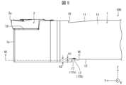
- the second side surface 12 may have a first region 15, a second region 16, and a stepped portion 17.
- the first region 15 is, for example, a flat region located on the side of the first end 1a.
- the second region 16 is, for example, a flat region located closer to the second end 1 b than the first region 15 and closer to the first side surface 11 than the first region 15 .
- the step portion 17 connects the first region 15 and the second region 16, for example.
- the stepped portion 17 is located closer to the second end 1b than the projecting stepped portion 18 is.
- the stepped portion 17 is a portion for positioning the cutting tool 100 on the tool post 4 and is engaged with the tool post 4 .
- the positioning member is not a separate member from the cutting tool holder, but a part of the holder 1 . Therefore, it is not necessary to consider the machining accuracy of the portion of the holder to which the positioning member is attached and the attachment accuracy when attaching the positioning member to the holder.
- the stepped portion 17 has a curved shape that protrudes toward the second end 1b in a cross section parallel to the first region 15.
- the stepped portion 17 has a curved shape that protrudes toward the second end 1b in the cross section described above, and has a curved surface that has a constant width in the Y-axis direction. If the stepped portion 17 has a linear shape in the cross section described above, that is, if the stepped portion 17 is provided so as to extend straight in the X-axis direction in FIG. may be extremely inclined toward the first end 1a side or the second end 1b side.
- FIG. 11 shows the blade post when the stepped portion 17 is formed so as to extend straight in the Z-axis direction, and the stepped portion 17 is inclined toward the first end 1a due to a processing error.
- 4 is an enlarged side view showing a state in which the right corner of the locking portion of 4 is in contact with the stepped portion 17.
- FIG. 11 Even if the holder 1 and the tool post 4 are elastically deformed, under the condition that the stepped portion 17 is extremely inclined as described above, the contact area of the locking portion of the holder 1 and the tool post 4 is limited, and substantially , the situation remains the same as that of point contact.
- the stepped portion 17 is configured to form a convex curved shape toward the second end 1b, it makes point contact with the engaging portion of the tool post 4 along the curved line, and actually makes surface contact due to elastic deformation. Stable positioning can be easily performed (see FIG. 10). Even if a machining error occurs in the stepped portion 17, the error is absorbed by the curved line. When a cutting load is applied, the load is absorbed, and the positioning accuracy, in other words, the attachment accuracy to the tool rest 4 can be maintained, and the machining accuracy of cutting is excellent.
- the stepped portion 17 may have an arc shape in the cross section described above. In this case, it is possible to further reduce the influence when a machining error occurs in the step portion 17 .
- At least part of the stepped portion 17 may be located in a region where the pocket 19 is extended toward the second end 1b. In this case, at least a part of the stepped portion 17 is located behind the pocket 19, and can absorb the cutting load during cutting, thereby maintaining good positioning accuracy.
- the stepped portion 17 may be in contact with the third side surface 13 and the fourth side surface 14 .
- the stepped portion 17 is provided over the entire width of the second side surface 12, which has high durability against cutting load and can maintain good positioning accuracy.
- the stepped portion 17 has a tip portion 17a positioned closest to the second end 1b, and the length from the tip portion 17a to the fourth side surface 14 is longer than the tip portion 17a.
- the length from 17a to the third side surface 13 may be short. In this case, the thickness of the tip portion 11a having the pocket 19 can be ensured, and the durability against the cutting load is increased.
- the tip portion 17a may be in contact with the third side surface 13.
- the stepped portion 17 is provided over a wide range of the second side surface 12 and has high durability against cutting load.
- the second side surface 12 on which the stepped portion 17 is formed may be separated from the pocket 19 .
- the cutting load is better than forming the stepped portion 17 on the first side surface 11 or the third side surface 13 on which the pocket 19 is formed. can be received, and the positioning accuracy is good.
- the stepped portion 17 is provided on the second side surface 12 , but the present invention is not limited to this. As will be described later, it may be provided on the first side surface 11 or the third side surface 13 that can be engaged with the tool post 4 .
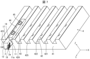
- FIG. 7 is a perspective view showing a state in which the cutting tool 100 is supported by the tool post 4 according to a non-limiting embodiment of the present disclosure.
- 8 is a plan view of the cutting tool 100 and the tool post 4 shown in FIG. 7.
- FIG. 9 is a side view of the cutting tool 100 and the tool post 4 shown in FIG. 7 of FIG. 8.
- FIG. 10 is an enlarged side view of a portion of the front portion of FIG. 9.
- the X-axis direction is the horizontal direction
- the Z-axis direction is the vertical direction
- the Y-axis direction is the front-back direction.
- the side where the insert 2 is located is the right side in the X-axis direction
- the side where the fourth side surface 14 is located is the upper side in the Z-axis direction.
- the tool post 4 has a base 41 , a plurality of support portions 42 , screw holes 43 , a holding portion 44 and set screws 45 .
- the base 41 has the shape of a rectangular plate whose dimension in the X-axis direction is longer than the dimension in the Y-axis direction.
- a plurality of support portions 42 extending in the Y-axis direction are provided on the base 41 in a comb shape.
- a tool post provided with a plurality of support portions 42 in a comb-like shape is generally called a comb-tooth tool post.
- the support portion 42 has a right side 421 , a left side 422 , a front end surface 423 and a bottom surface 425 .
- the bottom surface 425 is the bottom of the comb-shaped groove and faces upward.
- Right side 421 rises upward from bottom 425 .
- the left side surface 422 has a shape that rises upward from the bottom surface 425 and then tilts upward to the right.
- the front end surface 423 is located on the front side between the right side surface 421 and the left side surface 422 .
- the holding portion 44 is L-shaped when viewed from the front.
- the clamping part 44 is inserted between the cutting tool 100 and the left side surface 422 with the L-shaped vertical side abutting on the oblique portion of the left side 422, and the set screw 45 is inserted through the L-shaped horizontal side. By doing so, it is screwed into the screw hole 43 of the support portion 42 .
- the cutting tool 100 faces the first side surface 11 to the right so that the tip portion 11a is positioned forward, and the right corner portion 424 of the front end surface 423 of the support portion 42 is locked to the stepped portion 17. It is placed between the supporting portion 42 and the supporting portion 42 .
- the stepped portion 17 has a convex curved shape toward the second end 1b in a cross-sectional view. Therefore, as shown in FIG. and can be positioned well.
- the cutting tool 100 is fixed to the tool post 4 by inserting the holding portion 44 between the first side surface 11 and the adjacent support portion 42 and screwing the setscrew 45 into the screw hole 43 . .
- the right corner portion 424 can come into surface contact with the stepped portion 17 even if a machining error occurs in the stepped portion 17 .
- the load is absorbed and the positioning accuracy is maintained.
- FIG. 11 shows the right corner portion 424 when the stepped portion 27 is inclined toward the first end 1a due to a processing error when the stepped portion is provided so as to extend straight in the Z-axis direction. is in contact with the stepped portion 27; As shown in FIG. 11, the right corner portion 424 is in point contact with the stepped portion 27, which makes it easy to move and difficult to position.
- a plurality of cutting tools 100 are supported between the support portions 42 , 42 .
- the cutting tool 100 can be well positioned in the Y-axis direction, and the protrusion amount of the tip portion 11a from the base 41 can be well aligned between the cutting tools 100. . Therefore, the same work material can be machined in sequence with a plurality of cutting tools 100 with high accuracy. Even if a cutting load is applied during cutting, it can be absorbed by the stepped portion 17, and the positioning accuracy can be maintained.
- the stepped portion 17 may have a groove shape recessed toward the first side surface 11 .
- the stepped portion 17 may have a bottom surface 17 b closest to the first side surface 11 . It can also be said that the bottom surface 17 b is positioned closest to the first side surface 11 in the stepped portion 17 . At this time, the bottom surface 17b may be positioned closer to the first side surface 11 than the second region 16, as in the example shown in FIG.
- a wall surface rising from the bottom surface 17b of the stepped portion 17 and facing the bottom surface 17b is referred to as a wall surface 17c shown in FIG.
- the strength of the boundary between the bottom surface 17b and the wall surface 17c tends to be relatively small.
- the cutting tool 100 is attached to the tool post 4
- if the right corner portion 424 comes into contact with this boundary cracks may occur at the boundary.
- the stepped portion 17 has the above configuration, it is difficult for the right corner portion 424 to come into contact with the above boundary. Therefore, deterioration of the strength of the holder 1 can be avoided.
- the height h1 from the bottom surface 17b to the second region 16 may be smaller than the height h2 from the second region 16 to the first region 15.
- “height” means the width in the vertical direction of the Z-axis.
- a workpiece 101 is produced by cutting a workpiece 103 .
- the manufacturing method of the cut workpiece 101 in the embodiment includes the following steps. i.e. (1) a step of rotating the work material 103; (2) A step of contacting the rotating work material 103 with the cutting tool 100 represented by the above embodiment; (3) separating the cutting tool 100 from the work material 103; Prepare.
- the cutting tool 100 is moved in the forward direction of the Y-axis with the second central axis L2 fixed and the work material 103 rotated. bring closer.
- the cutting tool 100 is moved downward along the Z-axis and forward along the Y-axis while at least a part of the portion of the insert 2 that is used as the cutting edge 2a of the insert 2 is in contact with the rotating workpiece 103.
- the work material 103 is cut by moving in the direction.
- the cutting tool 100 is moved away from the work material 103 by moving the cutting tool 100 in the backward direction of the Y-axis while the work material 103 is being rotated.
- the cutting tool 100 is brought into contact with the work material 103 or separated from the work material 103 by moving the cutting tool 100, but the present invention is not limited to this case.
- step (1) the work material 103 may be brought closer to the cutting tool 100 .
- step (3) the work material 103 may be kept away from the cutting tool 100 .
- Another cutting tool 100 supported on the tool rest 4 may be used to continuously cut the material 103 to be cut.
- Representative examples of the material of the work material 103 include hardened steel, carbon steel, alloy steel, stainless steel, cast iron, non-ferrous metals, and the like.
- the cutting tool 100 of the present disclosure is satisfactorily positioned on the tool post 4 and the holder 1 by the stepped portion 17, so that machining can be performed with high accuracy.
- the amount of protrusion from the base 41 can be made uniform, so machining can be performed in sequence with high accuracy.
Landscapes
- Engineering & Computer Science (AREA)
- Mechanical Engineering (AREA)
- Cutting Tools, Boring Holders, And Turrets (AREA)
Abstract
Le support se présente sous la forme d'un prisme quadrangulaire s'étendant d'une première extrémité à une seconde extrémité. Le support comprend une poche située sur le premier côté d'extrémité, et une première surface latérale et une seconde surface latérale qui s'étendent de la première extrémité à la seconde extrémité. La seconde surface latérale comprend une première région qui est plate et située sur le premier côté d'extrémité, une seconde région qui est plate et située plus près de la seconde extrémité et que la première surface latérale que la première région, et une partie étagée raccordant la première région et la seconde région. La partie étagée présente une forme incurvée faisant saillie vers la seconde extrémité dans une section transversale parallèle à la première région.
Priority Applications (2)
| Application Number | Priority Date | Filing Date | Title |
|---|---|---|---|
| JP2023552859A JPWO2023058588A1 (fr) | 2021-10-06 | 2022-10-03 | |
| CN202280064429.XA CN117980097A (zh) | 2021-10-06 | 2022-10-03 | 刀柄、切削刀具以及切削加工物的制造方法 |
Applications Claiming Priority (2)
| Application Number | Priority Date | Filing Date | Title |
|---|---|---|---|
| JP2021-164670 | 2021-10-06 | ||
| JP2021164670 | 2021-10-06 |
Publications (1)
| Publication Number | Publication Date |
|---|---|
| WO2023058588A1 true WO2023058588A1 (fr) | 2023-04-13 |
Family
ID=85804224
Family Applications (1)
| Application Number | Title | Priority Date | Filing Date |
|---|---|---|---|
| PCT/JP2022/036897 WO2023058588A1 (fr) | 2021-10-06 | 2022-10-03 | Support, outil de découpe, et procédé de fabrication de pièce usinée |
Country Status (3)
| Country | Link |
|---|---|
| JP (1) | JPWO2023058588A1 (fr) |
| CN (1) | CN117980097A (fr) |
| WO (1) | WO2023058588A1 (fr) |
Citations (4)
| Publication number | Priority date | Publication date | Assignee | Title |
|---|---|---|---|---|
| JP2002346808A (ja) * | 2001-03-19 | 2002-12-04 | Suzuki Seiko:Kk | 旋盤用バイトユニット |
| US20160136733A1 (en) * | 2014-11-19 | 2016-05-19 | Kennametal Inc. | Tool holder for a cutting insert |
| JP2020028943A (ja) * | 2018-08-22 | 2020-02-27 | 京セラ株式会社 | ホルダ、切削工具及び切削加工物の製造方法 |
| JP2020104219A (ja) * | 2018-12-27 | 2020-07-09 | 三菱マテリアル株式会社 | 切削インサートおよび刃先交換式切削工具 |
-
2022
- 2022-10-03 JP JP2023552859A patent/JPWO2023058588A1/ja active Pending
- 2022-10-03 WO PCT/JP2022/036897 patent/WO2023058588A1/fr active Application Filing
- 2022-10-03 CN CN202280064429.XA patent/CN117980097A/zh active Pending
Patent Citations (4)
| Publication number | Priority date | Publication date | Assignee | Title |
|---|---|---|---|---|
| JP2002346808A (ja) * | 2001-03-19 | 2002-12-04 | Suzuki Seiko:Kk | 旋盤用バイトユニット |
| US20160136733A1 (en) * | 2014-11-19 | 2016-05-19 | Kennametal Inc. | Tool holder for a cutting insert |
| JP2020028943A (ja) * | 2018-08-22 | 2020-02-27 | 京セラ株式会社 | ホルダ、切削工具及び切削加工物の製造方法 |
| JP2020104219A (ja) * | 2018-12-27 | 2020-07-09 | 三菱マテリアル株式会社 | 切削インサートおよび刃先交換式切削工具 |
Also Published As
| Publication number | Publication date |
|---|---|
| JPWO2023058588A1 (fr) | 2023-04-13 |
| CN117980097A (zh) | 2024-05-03 |
Similar Documents
| Publication | Publication Date | Title |
|---|---|---|
| JP6685531B2 (ja) | 切削インサート、切削工具及び切削加工物の製造方法 | |
| JP7128185B2 (ja) | 切削インサート、切削工具及び切削加工物の製造方法 | |
| JP2012045692A (ja) | 切削工具および切削工具を用いた被削材の切削方法 | |
| WO2023058588A1 (fr) | Support, outil de découpe, et procédé de fabrication de pièce usinée | |
| JP7368064B2 (ja) | 工作機械及び切削加工物の製造方法 | |
| JP2020028943A (ja) | ホルダ、切削工具及び切削加工物の製造方法 | |
| CN110944777B (zh) | 切削刀片、切削工具以及切削加工物的制造方法 | |
| KR20080047387A (ko) | 브로치 공구 및 브로치 인서트 | |
| WO2023176441A1 (fr) | Outil de coupe et procédé de production de pièce coupée | |
| JP3286836B2 (ja) | スローアウェイバイト及びそのシャンク | |
| WO2024048256A1 (fr) | Unité de coupe, outil de coupe et porte-outil de coupe, et procédé de fabrication d'article coupé | |
| WO2023058589A1 (fr) | Outil de coupe et procédé de production d'une pièce découpée | |
| JP7117389B2 (ja) | 切削インサート、切削工具及び切削加工物の製造方法 | |
| WO2024024488A1 (fr) | Outil de coupe et procédé de fabrication d'une pièce à travailler coupée | |
| WO2023277182A1 (fr) | Plaquette de coupe, outil de coupe et procédé de fabrication de produit usiné | |
| WO2023277181A1 (fr) | Plaquette de coupe, outil de coupe et procédé de fabrication de produit usiné | |
| JP7225387B2 (ja) | クランプ部材、工作機械及び切削加工物の製造方法 | |
| WO2023084973A1 (fr) | Plaquette de coupe, outil de coupe, et procédé de fabrication de pièce coupée | |
| WO2023277180A1 (fr) | Support, outil de coupe et procédé de fabrication de produit usiné | |
| JP7344385B2 (ja) | 切削インサート、切削工具及び切削加工物の製造方法 | |
| JP7344168B2 (ja) | 切削インサート、切削工具及び切削加工物の製造方法 | |
| CN113474110B (zh) | 车削刀具及切削加工物的制造方法 | |
| US11833595B2 (en) | Cutting insert, cutting tool, and method for manufacturing machined product | |
| CN113474109A (zh) | 切削刀片、切削刀具及切削加工物的制造方法 | |
| JP6418765B2 (ja) | 切削インサート、切削工具および切削加工物の製造方法 |
Legal Events
| Date | Code | Title | Description |
|---|---|---|---|
| 121 | Ep: the epo has been informed by wipo that ep was designated in this application |
Ref document number: 22878457 Country of ref document: EP Kind code of ref document: A1 |
|
| WWE | Wipo information: entry into national phase |
Ref document number: 2023552859 Country of ref document: JP |
|
| WWE | Wipo information: entry into national phase |
Ref document number: 202280064429.X Country of ref document: CN |