WO2023058341A1 - 切断装置及び複層材 - Google Patents
切断装置及び複層材 Download PDFInfo
- Publication number
- WO2023058341A1 WO2023058341A1 PCT/JP2022/031527 JP2022031527W WO2023058341A1 WO 2023058341 A1 WO2023058341 A1 WO 2023058341A1 JP 2022031527 W JP2022031527 W JP 2022031527W WO 2023058341 A1 WO2023058341 A1 WO 2023058341A1
- Authority
- WO
- WIPO (PCT)
- Prior art keywords
- tool
- blade
- slit
- steel sheet
- plated steel
- Prior art date
- Legal status (The legal status is an assumption and is not a legal conclusion. Google has not performed a legal analysis and makes no representation as to the accuracy of the status listed.)
- Ceased
Links
Images









Classifications
-
- B—PERFORMING OPERATIONS; TRANSPORTING
- B23—MACHINE TOOLS; METAL-WORKING NOT OTHERWISE PROVIDED FOR
- B23D—PLANING; SLOTTING; SHEARING; BROACHING; SAWING; FILING; SCRAPING; LIKE OPERATIONS FOR WORKING METAL BY REMOVING MATERIAL, NOT OTHERWISE PROVIDED FOR
- B23D19/00—Shearing machines or shearing devices cutting by rotary discs
- B23D19/04—Shearing machines or shearing devices cutting by rotary discs having rotary shearing discs arranged in co-operating pairs
- B23D19/06—Shearing machines or shearing devices cutting by rotary discs having rotary shearing discs arranged in co-operating pairs with several spaced pairs of shearing discs working simultaneously, e.g. for trimming or making strips
-
- B—PERFORMING OPERATIONS; TRANSPORTING
- B21—MECHANICAL METAL-WORKING WITHOUT ESSENTIALLY REMOVING MATERIAL; PUNCHING METAL
- B21D—WORKING OR PROCESSING OF SHEET METAL OR METAL TUBES, RODS OR PROFILES WITHOUT ESSENTIALLY REMOVING MATERIAL; PUNCHING METAL
- B21D28/00—Shaping by press-cutting; Perforating
- B21D28/02—Punching blanks or articles with or without obtaining scrap; Notching
-
- B—PERFORMING OPERATIONS; TRANSPORTING
- B21—MECHANICAL METAL-WORKING WITHOUT ESSENTIALLY REMOVING MATERIAL; PUNCHING METAL
- B21D—WORKING OR PROCESSING OF SHEET METAL OR METAL TUBES, RODS OR PROFILES WITHOUT ESSENTIALLY REMOVING MATERIAL; PUNCHING METAL
- B21D28/00—Shaping by press-cutting; Perforating
- B21D28/02—Punching blanks or articles with or without obtaining scrap; Notching
- B21D28/16—Shoulder or burr prevention, e.g. fine-blanking
-
- B—PERFORMING OPERATIONS; TRANSPORTING
- B23—MACHINE TOOLS; METAL-WORKING NOT OTHERWISE PROVIDED FOR
- B23D—PLANING; SLOTTING; SHEARING; BROACHING; SAWING; FILING; SCRAPING; LIKE OPERATIONS FOR WORKING METAL BY REMOVING MATERIAL, NOT OTHERWISE PROVIDED FOR
- B23D35/00—Tools for shearing machines or shearing devices; Holders or chucks for shearing tools
- B23D35/001—Tools for shearing machines or shearing devices; Holders or chucks for shearing tools cutting members
-
- B—PERFORMING OPERATIONS; TRANSPORTING
- B32—LAYERED PRODUCTS
- B32B—LAYERED PRODUCTS, i.e. PRODUCTS BUILT-UP OF STRATA OF FLAT OR NON-FLAT, e.g. CELLULAR OR HONEYCOMB, FORM
- B32B1/00—Layered products having a non-planar shape
-
- B—PERFORMING OPERATIONS; TRANSPORTING
- B32—LAYERED PRODUCTS
- B32B—LAYERED PRODUCTS, i.e. PRODUCTS BUILT-UP OF STRATA OF FLAT OR NON-FLAT, e.g. CELLULAR OR HONEYCOMB, FORM
- B32B15/00—Layered products comprising a layer of metal
- B32B15/01—Layered products comprising a layer of metal all layers being exclusively metallic
-
- B—PERFORMING OPERATIONS; TRANSPORTING
- B32—LAYERED PRODUCTS
- B32B—LAYERED PRODUCTS, i.e. PRODUCTS BUILT-UP OF STRATA OF FLAT OR NON-FLAT, e.g. CELLULAR OR HONEYCOMB, FORM
- B32B15/00—Layered products comprising a layer of metal
- B32B15/18—Layered products comprising a layer of metal comprising iron or steel
-
- B—PERFORMING OPERATIONS; TRANSPORTING
- B32—LAYERED PRODUCTS
- B32B—LAYERED PRODUCTS, i.e. PRODUCTS BUILT-UP OF STRATA OF FLAT OR NON-FLAT, e.g. CELLULAR OR HONEYCOMB, FORM
- B32B15/00—Layered products comprising a layer of metal
- B32B15/01—Layered products comprising a layer of metal all layers being exclusively metallic
- B32B15/013—Layered products comprising a layer of metal all layers being exclusively metallic one layer being formed of an iron alloy or steel, another layer being formed of a metal other than iron or aluminium
Definitions
- the present invention relates to a cutting device for cutting a multilayer material and a multilayer material having a cut end surface.
- Multi-layered materials which are coated with a coating material on the surface of the base material, such as plated steel sheets that have been plated on the surface of steel sheets, or coated steel sheets that have been coated on the surface of steel sheets, are manufactured according to the application. It's being used.
- the reason why the base material is coated with a coating material is that, for example, in the case of plated steel sheets used for building materials, automobiles, and home appliances, the coating material (plating) improves the corrosion resistance compared to the base material (steel sheet) as it is. That's what it is.
- the manufacturing process of parts and the like made of a multi-layer material includes a process of cutting a necessary member from an original sheet, such as shearing and laser cutting.
- the cut end surface formed by this cutting process includes a sheared surface and a broken surface where the base material is substantially exposed.
- the base material exposed portion of the cut end face does not exhibit the effect obtained by the coating material.
- the corrosion resistance improvement effect by plating cannot be obtained at the base material exposed portion of the cut end face, and there is concern about the generation of red rust.
- Patent Document 1 a covering material is provided between two groove-forming round blades arranged facing each other vertically with a tip angle ⁇ of 20 to 70° and a tip R of 0.03 to 0.30 mm. After passing a steel plate having a A steel plate cutting method is disclosed in which the steel plate is passed between round blades to cut the steel plate so that the plating wraps around the end faces.
- Patent Document 2 discloses a shearing die consisting of a die having a first shearing blade and a die having a second shearing blade.
- a mold having a second shear blade includes, behind the second shear blade, a second shear blade having a smaller clearance with the first shear blade than the clearance between the second shear blade and the first shear blade. Equipped with 3 shear blades.
- a cut edge produced by shearing when the workpiece is sheared by the first shearing blade and the second shearing blade is treated as a first shearing blade and a first shearing blade having an inclined blade surface. Scraping with the shear blades of 3 removes sag without causing burrs and obtains a good cut.
- the present invention has been made in view of the above problems, and the object of the present invention is to exhibit the effect obtained by the coating material on the cut end surface to the same extent as on the front and back surfaces, and to To provide a cutting device and a multilayer material capable of satisfying specifications required for the multilayer material.
- a cutting device for cutting a multilayer material sandwiched between a first tool and a second tool, wherein the first tool and the second tool
- the tools are arranged so that their blade portions face each other in the pushing direction, and the blade portion of at least one of the first tool and the second tool has a tool inclined surface that is inclined with respect to the pushing direction.
- a vertical wall surface extending along the pushing direction from the tool inclined surface, and a pressing surface orthogonal to the vertical wall surface, and a protrusion projecting from the inclined portion in the pushing direction, provides a cutting device that overlaps the opposing tool when viewed in the pushing direction.
- the inclination angle of the tool inclined surface with respect to the pushing direction may be 15° or more and 45° or less.
- the length of the vertical wall surface in the pushing direction may be 0.1 mm or more and 0.8 mm or less.
- the first tool and the second tool may each have an inclined portion and a protrusion.
- the curvature radius of the corner where the vertical wall surface and the pressing surface intersect may be 0.1 mm or less.
- the shape of the first tool and the shape of the second tool may be symmetrical.
- a multilayer material in which the surface of a base material is coated with a coating material, and the It has a cut end surface along the plate thickness direction, the cut end surface has an inclined surface inclined with respect to the plate thickness direction and a fracture surface in order, and at least part of the inclined surface is the first
- a multi-ply material is provided that is coated with a coating that is continuous from the surface of the.
- the length of the fracture surface in the thickness direction of the multilayer material may be 30% or less of the thickness of the multilayer material.
- the first surface of the multilayer material may intersect the inclined surface, the second surface may intersect the fracture surface, and the internal angle between the first surface and the inclined surface may be an obtuse angle.
- a material made of Zn, Al, or an alloy thereof may be used as the coating material.
- the base material may be a steel plate.
- the effect obtained by the coating material on the cut end surface is exhibited to the same extent as on the front and back surfaces, and the specifications required for the multi-layer material after cutting, such as suppression of burr generation, are also satisfied. becomes possible.
- FIG. 3 is a sectional view of the slit device shown in FIG. 2 taken along line II. It is a partial enlarged view of the upper rotation part and the lower rotation part of the slit device according to the same embodiment, showing a case where the shape of the pair of slit blade parts is different.
- FIG. 4 is a schematic diagram showing a cutting state when the blade portion of the first slit blade has an inclined portion and projections, and the second slit blade is a right angle blade.
- FIG. 4 is a schematic diagram showing a cutting state when the blade portion of the first slit blade and the blade portion of the second slit blade have inclined portions and protrusions;
- FIG. 10 is a schematic diagram showing an example of a cut end surface of the plated steel sheet after being cut by the pair of slit blades shown in FIG. 8 or FIG. 9;
- FIG. 10 is a schematic diagram showing another example of a cut end face of the plated steel sheet after being cut by the pair of slit blades shown in FIG. 8 or 9; It is a schematic diagram which shows the cross-sectional shape of the blade part of the 1st slit blade which concerns on the same embodiment. It is explanatory drawing which shows the punching process by the punching die of a comparative example.
- FIG. 4 is a schematic diagram showing an example of a blade portion of a punch (tool) of the pressing die; It is a schematic diagram which shows an example of the blade part of the shear (tool) of a shear cutting machine.
- FIG. 1 is a schematic diagram showing a configuration example of a slitting facility provided with a slitting device 100, which is an example of a cutting device according to the present embodiment.
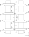
- FIG. 2 is a schematic diagram showing a configuration example of the slit device 100 according to this embodiment.
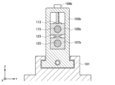
- FIG. 3 is a cross-sectional view of the slit device 100 shown in FIG. 2 taken along line II.
- FIG. 1 is a schematic diagram showing a configuration example of a slitting facility provided with a slitting device 100, which is an example of a cutting device according to the present embodiment.
- FIG. 2 is a schematic diagram showing a configuration example of the slit device 100 according to this embodiment.
- FIG. 3 is a cross-sectional view of the slit device 100 shown in FIG. 2 taken along line II.
- FIG. 1 is a schematic diagram showing a configuration example of a slitting facility provided with a slitting device 100, which is an example of a cutting device according
- FIG. 4 is a partially enlarged view of the upper rotating portion 50A and the lower rotating portion 50B of the slit device 100 according to the present embodiment, and shows a case where the shape of the pair of slit blade portions is different.
- FIG. 5 is a partially enlarged view of the upper rotating portion 50A and the lower rotating portion 50B of the slit device 100, showing a case where the pair of slit blade portions have vertically symmetrical shapes.
- a plated steel sheet S in which the surface of a steel sheet as a base material is coated with plating as a coating material will be taken up. 1 to 5, the length direction of the plated steel sheet S is the X direction, the width direction of the plated steel sheet S is the Y direction, and the thickness direction is the Z direction.
- the Y direction is also the direction in which the plated steel sheet S is passed.
- the Z direction is also the pushing direction of the tool (slit blade).
- the slitting equipment is equipment for cutting the plated steel sheet S to be cut with a slitting device 100 having a pair of rotating blades.
- the slitting equipment includes, for example, a payoff reel 10, a tension generator 20, a tension reel 30, and a slitting device 100, as shown in FIG.
- a plated steel sheet S wound in a coil shape is discharged from a payoff reel 10, and the plated steel sheet S is cut by a shearing force by a slitting device 100 while tension is applied between the payoff reel 10 and a tension generator 20.
- the slit device 100 shown in FIG. 1 divides the plated steel sheet S into three parts in the width direction.
- the plated steel sheet S cut by the slit device 100 is wound into a coil shape by the tension reel 30 .
- the slit device 100 includes four pairs of slit blades 1, 2, 3, and 4, as shown in FIG. 2, for example.
- the slit device 100 may have at least one pair of slit blades.
- the pair of slit blades 1, 2, 3 and 4 are respectively composed of first slit blades 111, 112, 113 and 114 which are first tools, and second slit blades 121 and 122 which are second tools. 123 and 124.
- the paired first slit blades 111, 112, 113, 114 and the second slit blades 121, 122, 123, 124 are arranged to face each other in the pushing direction (Z direction) as shown in FIG.
- each pair of slit blades 1, 2, 3, and 4 the blade portions 111a, 112a, 113a, 114a, 121a, 122a, 123a, and 124a on the outer edge of the slit blades are aligned in the rotation axis direction ( They overlap each other when viewed from the X direction).
- the shapes of the first slit blades 111, 112, 113 and 114 shown in FIGS. 2 and 4 are different from the shapes of the second slit blades 121, 122, 123 and 124.
- the blade portions 111a, 112a, 113a, and 114a of the first slit blades 111, 112, 113, and 114 have, when viewed from the front, an inclined portion having a tool inclined surface inclined with respect to the pushing direction (Z direction), and an inclined portion having an inclined surface. and a projecting portion projecting from the portion in the pushing direction.
- the blade portions 121a, 122a, 123a, and 124a of the second slit blades 121, 122, 123, and 124 are right-angled blades with substantially right-angled corners. 2 and 4, at least one of the first slit blades 111, 112, 113 and 114 and the second slit blades 121, 122, 123 and 124 is , a blade having an inclined portion and a protrusion.
- the first slit blades 111, 112, 113, 114 and the second slit blades 121, 122, 123, 124 each have a blade portion having an inclined portion and a projection portion. may A detailed description of the shape of the blade portion of the slit blade will be given later.
- the first slit blades 111, 112, 113, and 114 are supported by the first shaft portion 115 at the center of rotation.
- the second slit blades 121, 122, 123, and 124 are supported by a second shaft portion 125 at the center of rotation.
- the first shaft portion 115 is rotatable via chocks 105a and 105b
- the second shaft portion 125 is rotatable via chocks 107a and 107b
- both ends thereof are rotatable by a pair of support portions 103a and 103b.
- the chocks 105a and 107a on the back side of the paper are not shown.).
- a pair of support portions 103a and 103b are provided on the pedestal 101 in FIG.
- sleeves 151 and 153 may be provided together with the first slit blades 111, 112, 113 and 114 and the second slit blades 121, 122, 123 and 124.
- the sleeves 151 , 153 are members for adjusting the intervals between the first slit blades 111 , 112 , 113 , 114 and the intervals between the second slit blades 121 , 122 , 123 , 124 .
- sleeves 151 and 153 with different widths are provided in FIG. , 122, 123, 124 may be adjusted.
- the first slit blades 111, 112, 113, 114 and the sleeves 151, 153 supported by the first shaft portion 115 are also referred to as an upper rotating portion 50A.
- the second slit blades 121, 122, 123, 124 and the sleeves 151, 153 supported by the second shaft portion 125 are also referred to as a lower rotation portion 50B.
- the upper rotating portion 50A rotates integrally with the first shaft portion 115 .
- the lower rotating portion 50B rotates integrally with the second shaft portion 125. As shown in FIG.
- the pair of support portions 103a and 103b are movable in the plate width direction (X direction) by drive portions 104a and 104b, respectively.
- a pair of support portions 103a and 103b are screwed into screw portions 102a and 102b installed parallel to the first shaft portion 115 and the second shaft portion 125, respectively.
- One ends of the screw portions 102a and 102b are connected to the driving portions 104a and 104b.
- the drive portions 104a and 104b By driving the drive portions 104a and 104b to rotate the screw portions 102a and 102b, the support portions 103a and 103b are moved.
- One end of the first shaft portion 115 and the second shaft portion 125 is separated from the chock by driving the drive portions 104a and 104b and moving the support portions 103a and 103b in the plate width direction so as to separate them.
- the sleeves 151, 153, the first slit blades 111, 112, 113, 114, and the second slit blades 121, 122, 123, 124 are removed from the first shaft portion 115 and the second shaft portion 125. It becomes possible to change the slit blades or the sleeve for adjusting the spacing between them.
- a screw down Devices 109a, 109b are provided on the upper part of the support parts 103a and 103b.
- the gaps between the first slit blades 111, 112, 113 and 114 and the second slit blades 121, 122, 123 and 124 can be narrowed by tightening the screw down devices 109a and 109b.
- the slitting device 100 uses first slitting blades 111, 112, 113, and 114 and second slitting blades 121, 122, and 123 according to the plate thickness of the plated steel sheet S by the screw-down devices 109a and 109b. , 124 are adjusted. Thereafter, the plated steel sheet S is passed between the upper rotating part 50A and the lower rotating part 50B while being rotated, and the plated steel sheet S is cut. When the plated steel sheet S passes between the upper rotating part 50A and the lower rotating part 50B, the pair of slitting blades 1, 2, 3, 4 are gradually pushed in the pushing direction (Z direction), and shear force A plated steel sheet S is cut.
- the plated steel sheet S Due to the tensile force generated between the cutting edges of the first slit blades 111, 112, 113, and 114 and the cutting edges of the second slit blades 121, 122, 123, and 124, and the plated steel sheet S, the plated steel sheet S The plated layer on the surface penetrates into the cut end face, and the cut end face is covered with the plated layer.
- the plated layer on the surface of the plated steel sheet S is caused to follow the movements of the blade portions 121a, 122a, 123a, and 124a of the blades 121, 122, 123, and 124, and the plated layer enters the cut end face.
- the cut end surface of the plated steel sheet S is covered with the plating layer.
- the configuration of the slit device 100 according to the present embodiment and the slit equipment including the same has been described above.
- the first slit blades 111, 112, 113, and 114 are referred to as the "first slit blades 110”
- the second slit blades 121, 122, 123, and 124 are referred to as the "second slit blades 120.” described as.
- the blade portions 111a, 112a, 113a, and 114a of the first slit blade will be described as “blade portion 110a”
- the blade portions 121a, 122a, 123a, and 124a of the second slit blade will be described as "blade portion 120a”.
- a part using a multi-layer material is manufactured, for example, by cutting the multi-layer material with a cutting device and then processing it. At this time, the state of the cut end surface of the multilayer material differs depending on the shape of the blade of the cutting device that cuts the multilayer material.
- the state of the cut end surface when the plated steel sheet 5, which is an example of the multilayer material, is cut will be described in detail.
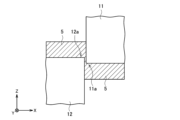
- the blade portion 11a of the first slit blade 11 and the blade portion 12a of the second slit blade 12 are both right angle blades.
- the plated steel plate 5 in which the plated layer 5b is coated on the upper surface (first surface) and the lower surface (second surface) of the base material 5a, which is a steel plate is applied to the first slit blade 11 and the second slit blade.
- a shearing force is applied to the plated steel sheet 5 and the plated steel sheet 5 is cut.
- FIG. 1 As shown in FIG.
- the cut end surface 5s at this time has a sheared surface and a fractured surface in order from the upper surface.
- the sheared surface is a smooth surface formed by the movement of the first slit blade 11 embedded in the plated steel sheet 5, and the fractured surface is a surface where the plated steel sheet 5 is fractured starting from a crack generated in the plated steel sheet 5. is.
- the plated layer 5b hardly remains on the sheared surface, and the base material 5a is exposed on the fractured surface. For this reason, such a cut end face 5s does not exhibit the effect obtained by the plating as a covering material, and there is concern that red rust may occur on the cut end face 5s.
- the corners of the blade are rounded (that is, rounded) by giving the corners a predetermined curvature radius. Conceivable.
- the corners of the blade part R-shaped By making the corners of the blade part R-shaped, the plating of the plated layer 5b of the plated steel sheet 5 when the blade part is pushed in wraps around the cutting end surface 5s along the R-shape of the corners of the blade part, and the corners of the tool Since the stress concentration in the portion is also alleviated, the cutting timing is delayed. Therefore, compared with the case of cutting the plated steel sheet 5 using the right-angled blade shown in FIG. 6, the coating coverage of the cut end surface 5s is increased, and the exposure of the base material 5a can be reduced. However, the cutting timing is too late, and the burr 5c projecting downward from the fracture surface of the cut end surface 5s becomes large.
- the plating of the plated layer 5b of the plated steel sheet 5 wraps around the cut end surface 5s along the inclined surface of the blade when the blade is pushed in, so the plated steel sheet 5 is cut using the right-angled blade shown in FIG.
- the plating coverage of the cut end surface 5s is higher than in the case where
- the corners of the cutting edge are angular, the stress concentration at the corners of the tool is not relieved, and cracks are generated so as to connect these corners. Therefore, the cutting timing is not delayed, and the exposed area (that is, fracture surface) of the base material 5a remains large.
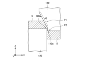
- the inventors of the present application have determined that at least one of the blade portion 110a of the first slit blade 110 and the blade portion 120a of the second slit blade 120 has a shape having an inclined portion and a protrusion. By doing so, it was found that the coating coverage of the cut end surface 5s of the plated steel sheet 5 can be increased without increasing the burr. That is, for example, as shown in FIG. 8, the blade portion 110a of the first slit blade 110 may be shaped to have an inclined portion P1 and projections P2, and the second slit blade 120 may be a right-angled blade. Further, for example, as shown in FIG. 9, the blade portion 110a of the first slit blade 110 and the blade portion 120a of the second slit blade 120 may have a shape having an inclined portion P1 and a projection portion P2.
- the inclined portion P1 overlaps the opposing tool when viewed in the pushing direction (Z direction).
- the inclined portion P1 of the blade portion 110a of the first slit blade 110 has an overlapping portion Q that overlaps with the opposing second slit blade 120 when viewed in the pushing direction (Z direction).
- the inclined portion P1 of the blade portion 110a of the first slit blade 110 has an overlapping portion Q that overlaps with the opposing second slit blade 120 in the pushing direction (Z direction) view
- the inclined portion P1 of the blade portion 120a of the second slit blade 120 has an overlapping portion Q that overlaps with the opposing first slit blade 110 when viewed in the pushing direction (Z direction).
- FIGS. 10A and 10B show an example of a cut end face 5s of the plated steel sheet 5 cut by the pair of slit blades shown in FIGS. 8 and 9.
- FIG. 10A and 10B show cutting on the side where the surface (upper surface, first surface) facing the inclined portion P1 of FIGS. 8 and 9 is pushed by the inclined portion P1 of the first slit blade 110 of FIGS.
- the end face 5s is shown.
- the cut end surface 5s has an inclined surface, a sheared surface and a fractured surface in order from the top surface.
- the inclined surface is a surface formed along the inclined portion P1 of the blade portion 110a of the first slit blade 110, and is inclined with respect to the plate thickness direction.
- the sheared surface is a smooth surface formed by the movement of the first slit blade 110 embedded in the plated steel sheet 5 and slightly generated.
- the fracture surface is a surface where the plated steel sheet 5 is broken starting from a crack that occurs in the plated steel sheet 5 .
- the upper surface (first surface) of the cut plated steel sheet 5 intersects the inclined surface.
- the internal angle ⁇ between the upper surface and the inclined surface is an obtuse angle of about ⁇ +90°, which is the inclination angle (taper angle) of the inclined surface of the tool, which will be described later.
- the lower surface (second surface) intersects the fracture surface. Since the plated steel sheet 5 is obliquely cut from the upper surface side to the lower surface side by the inclined portion P1 of the first slit blade 110, the cut end surface 5s has an inclined surface inclined in one direction from the upper surface side to the lower surface side. is formed.
- At least a part of the inclined surface of the cut end surface 5s of the plated steel sheet 5 is covered with a covering material continuous from the upper surface (first surface).
- a covering material continuous from the upper surface (first surface) For example, in the cut end surface 5s of the plated steel sheet 5 shown in FIG. 10A, the plated layer 5b on the upper surface wraps around the inclined surface and covers the inclined surface. 10A are all covered with the plating layer 5b continuous from the upper surface (first surface), but depending on the cutting method, for example, the cut end surface 5s of the plated steel sheet 5 shown in FIG. 10B
- the plated layer 5b on the upper surface that wraps around the inclined surface may become faint and the inclined surface may be discontinuously covered with the plated layer 5b.
- the cut end surface 5s has a sheared surface where almost no plating remains and a fractured surface where the base material 5a is exposed. Certain plating effects can be obtained.
- the final cutting that produces the fractured surface is cut by the protrusions P2 having substantially right angles at the corners, so the generation of large burrs is suppressed.
- the length of the fracture surface in the plate thickness direction of the plated steel plate 5 cut by the pair of slit blades according to the present embodiment is preferably 30% or less of the plate thickness of the plated steel plate 5, which is a multilayer material. . Thereby, the area
- the blade portion 110a of the first slit blade 110 has a shape having an inclined portion P1 and a projection portion P2
- the second slit blade 120 is a right-angled blade
- two slit blades are used.
- One of the divided plated steel sheets 5 after cutting has a cut end surface 5s as shown in FIG. 10A or FIG. 10B (plated steel sheet after cutting Sa in FIG. 4).
- the cut end surface 5s of the other plated steel sheet 5 is not coated with plating, it becomes scrap (the plated steel sheet after cutting Sb in FIG. 4).
- FIG. 10A or FIG. 10B plated steel sheet after cutting Sa in FIG. 4
- both of the post-cut plated steel sheets 5 can have cut end faces 5s as shown in FIG. 10A or FIG. 10B (post-cut plated steel sheet Sa in FIG. 5).
- FIG. 11 is a schematic diagram showing the cross-sectional shape of the blade portion 110a of the first slit blade 110 according to this embodiment. Note that FIG. 11 shows an enlarged view of the blade portion 110a when the slit blade 110 is cut on a plane including the rotation axis of the first slit blade 110. As shown in FIG. Note that even when the blade portion 120a of the second slit blade 120 has the slant portion P1 and the projection portion P2, the shape of the blade portion 120a is the same as in FIG.
- the section 110a will be described as an example.
- the plated steel sheet 5 will be described below as an example of the multi-layer material to be cut.
- a blade portion 110a having the cross-sectional shape shown in FIG. 11 has an inclined portion P1 and a projection portion P2.
- the inclined portion P1 has a tool inclined surface s1 inclined with respect to the pushing direction.
- the protrusion P2 has a vertical wall surface s2 extending from the tool inclined surface s1 along the pushing direction, and a pressing surface s3 perpendicular to the vertical wall surface s2. It is desirable that such a blade portion 110a satisfy the following shape.
- the inclination angle (taper angle) ⁇ of the tool inclined surface s1 with respect to the pushing direction is preferably 15° or more and 45° or less. If the angle of inclination ⁇ is 15° or more, it is possible to ensure cutting timing for sufficiently wrapping the plating of the plating layer 5b of the plated steel sheet 5 around the inclined surface. When the inclination angle ⁇ is about 5°, the cutting timing is about the same as that of the right angle blade.
- the slit blade 110 is loaded not only in the pushing direction (vertical direction) but also in the axial direction (horizontal direction). It becomes overloaded. If the inclination angle ⁇ is 45° or less, the load in the axial direction (horizontal direction) applied to the slit blade 110 does not become too large, and cutting can be performed within the withstand load of the equipment. When the angle of inclination ⁇ is made larger than 45°, the increase in the wraparound effect of the plating obtained with respect to the increase in the load is not so large. Therefore, the inclination angle (taper angle) ⁇ of the tool inclined surface s1 with respect to the pushing direction is preferably 15° or more and 45° or less.
- the length H of the vertical wall surface s2 in the pushing direction is desirably 0.1 mm or more and less than the thickness of the plated steel sheet 5 to be cut. If the length H of the vertical wall surface s2 is 0.1 mm or more, the burrs generated on the cut end surface 5s of the plated steel sheet 5 after cutting can be kept within an allowable range. Moreover, if the length H of the vertical wall surface s2 is set to 0.1 mm or more, the processing of the blade portion 110a can be facilitated. Furthermore, the blade portion 110a of the slit blade 110 wears as it is used. If the length H of the vertical wall surface s2 is set to 0.1 mm or more, the life of the slit blade 110 due to wear can be lengthened and the replacement frequency can be reduced.
- the length H of the vertical wall surface s2 is less than the plate thickness of the plated steel sheet 5 to be cut, it is possible to avoid cutting similar to that of a right-angled blade.
- the length H of the vertical wall surface s2 is smaller than the minimum thickness of 1.0 mm, for example 0.8 mm. And it is sufficient.
- the length H of the vertical wall surface s2 may be 1.6 mm, for example.
- the length H of the vertical wall surface s2 in the pushing direction is preferably 0.1 mm or more and less than the thickness of the plated steel sheet 5 to be cut.
- the curvature radius R of the corner c where the vertical wall surface s2 and the pressing surface s3 intersect is preferably 0.1 mm or less.
- the radius of curvature R of the corner c may be about 0.05 mm.
- the curvature radius R of the corner portion c does not depend on the plate thickness of the plated steel sheet 5 to be cut, and may be appropriately set according to the material of the plated steel sheet 5 and the like.
- the blade portion 110a has the shape described above, and as shown in FIGS.
- a slit blade 110 having a slit is arranged.
- the plating of the plating layer 5b including the base material 5a is compressed in the pushing direction (plate thickness direction) by the inclined portion P1 of the blade portion 110a.
- the cutting timing can be delayed and the inclined surface can be coated with plating.
- the effect obtained by plating, which is a coating material, on the cut end face can be enhanced.
- By completely cutting the plated steel sheet 5 with the protruding portion P2 of the blade portion 110a generation of large burrs can be suppressed.
- a punching process simulating slit cutting was performed to verify the effects of the present invention. In this verification, punching was performed using a punching die that simulated slitting by the slitting device 100 shown in FIG.
- the coating material to be cut was a 400N class Zn-Al-Mg ternary alloy plated steel sheet with a thickness of 3.2 mm.
- a punching die including a punch 71 with an outer diameter Dp, a die 72 with an inner diameter Dd, and a plate retainer 73 as shown in FIG. 12 was used.
- Punch 71 and die 72 had square edges.
- the plated steel sheet 5 placed on the die 72 was pressed by the plate retainer 73 , and the plated steel sheet 5 was punched by pressing the punch 71 from the plate retainer 73 side.
- a punching die including a punch 710 with an outer diameter Dp, a die 720 with an inner diameter Dd, and a plate retainer 730 as shown in FIG. 13 was used.
- the blade portion of the punch 710 had an inclined portion with an inclination angle ⁇ and a protruding portion with a height H of the vertical wall surface.
- the radius of curvature of the corners of the protrusions was 0.05 mm.
- the punch 710 was arranged so that the opposing die 720 and the inclined portion overlap each other when viewed in the punching direction.
- the plated steel sheet 5 placed on the die 720 was pressed by the plate retainer 730, and the plated steel sheet 5 was punched by pressing the punch 710 from the plate retainer 730 side.
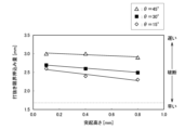
- the punching limit push-in amount is the push-in amount of the punch 710 from when the punch 710 starts to push until a crack occurs and the cutting object breaks. It can be said that the larger the punching limit pushing amount, the later the breaking timing.
- the length of the vertical wall surface (projection height) H of the projection is 0.1 mm, 0.4 mm, and 0.8 mm, respectively. changed.
- the verification result is shown in FIG.
- the dashed line in FIG. 14 indicates the punching limit pushing amount when the punching die of the comparative example shown in FIG. 12 is used.
- the punching limit pressing amount can be made larger than when processing is performed using the pressing die of the comparative example. It was also found that the maximum punching depth increases as the tilt angle ⁇ of the inclined portion increases, and the maximum punching depth increases as the length (height) H of the vertical wall surface of the protrusion decreases. That is, it was shown that the larger the inclination angle ⁇ of the inclined portion and the smaller the length (projection height) H of the vertical wall surface of the projection, the later the timing of breakage of the plated steel sheet 5 due to crack generation.
- the plating residual ratio is the ratio of the thickness direction length of the plating residual region (hereinafter also referred to as “plating residual region height”) Hp [mm] to the plate thickness t [mm] of the plated steel sheet 5, and is expressed by the following formula. (1).
- the cut end face was analyzed using a scanning electron microscope (SEM) to measure Zn, which is the main component of the plating, and Fe, which is the main component of the base material.
- the length of the vertical wall surface (projection height) H of the protrusion is 0.1 mm, 0.4 mm, 0.1 mm, 0.4 mm, 0.1 mm, 0.4 mm, 0.1 mm, 0.4 mm, 0.2 mm, 0.1 mm, 0.4 mm, 0.1 mm, 0.4 mm, 0.1 mm, 0.4 mm, 0.1 mm, 0.4 mm, 0.1 mm, 0.4 mm, and 0.2 mm. It was obtained by indenting the plated steel sheet 5 by changing it to 8 mm.
- Fig. 15 shows the verification results.
- the dashed line in FIG. 15 indicates the plating residual ratio when the punching die of the comparative example shown in FIG. 12 is used.
- the residual plating rate can be made larger than in the case of processing using the indentation die of the comparative example.
- the residual plating rate increased as the inclination angle ⁇ of the inclined portion increased, and the residual plating rate increased as the length (projection height) H of the vertical wall surface of the protrusion decreased. That is, it was shown that the greater the inclination angle ⁇ of the inclined portion and the shorter the length (projection height) H of the vertical wall surface of the projection, the higher the residual plating rate.
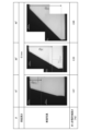
- FIG. 16 shows the plating after cutting when the length of the vertical wall surface (projection height) H of the projection is 0.1 mm and the inclination angle ⁇ of the inclined portion is 15°, 30°, and 45°.
- a photograph of the cross section of the steel sheet 5 and the height Hp of the plating residual region are shown. It can also be seen from FIG. 16 that when the length of the vertical wall surface (projection height) H of the projection is the same, the plated remaining area height Hp increases as the inclination angle ⁇ of the inclined portion increases.
- a slit cutting test was performed to verify the effects of the present invention.
- the slit cutting of the plated steel sheet was performed using a slit cutting tester equipped with a pair of slit blades.
- the multi-layer material to be cut was a 400N class Zn-Al-Mg ternary alloy plated steel sheet with a thickness of 3.2 mm.
- the plated steel sheet 5 was slit-cut using a slit cutting tester equipped with a pair of slit blades both having right-angled blades, as shown in FIG.
- the clearance between the pair of slit blades was 0.35 mm.
- one slit blade has a blade portion having an inclined portion with an inclination angle ⁇ and a protrusion with a vertical wall surface height H, and the other slit blade is a right angle blade.
- the plated steel sheet 5 was slit-cut using a slit-cutting tester equipped with a pair of slit blades.
- the inclination angle ⁇ of the inclined portion was 45°
- the height H of the vertical wall surface of the protrusion was 0.1 mm.
- One of the slit blades was arranged so that the inclined portion overlapped with the other slit blade facing each other when viewed in the pushing direction.
- FIG. 17 shows a cross-sectional photograph of the plated steel sheet 5 after cutting.
- the cut end face of the comparative example has sagging, a sheared surface and a fractured surface from the upper surface side, and the plating of the plating layer on the surface does not wrap around the sheared surface and the fractured surface. Recognize.
- the cut end surface of the example has an inclined surface and a fractured surface from the upper surface side. Almost no shear plane can be confirmed, but it exists slightly between the inclined plane and the fracture plane. It can be seen that the plating of the plating layer on the surface wraps around the inclined surface on the cut end face of the example.
- the inclination angle of the inclined surface of the cut end surface of the example is about 45°, which is the same as the inclination angle ⁇ of the inclined portion of the slit blade. Therefore, the inclined surface of the cut end surface is formed by the inclined portion of the slit blade. It has been shown.
- Example 1 the exposed plated steel sheet was cut using a slit blade having a blade portion with an inclination angle ⁇ of 30° and a vertical wall surface height H of the protrusion of 0.4 mm. A test was conducted. The plating residual rate of Example 1 was 74.1%.
- Example 2 the exposed plated steel sheet was cut using a slit blade having a blade portion with an inclination angle ⁇ of 45° and a vertical wall surface height H of the protrusion of 0.1 mm. A test was conducted. The plated steel sheet after cutting of Example 2 had the cut end face shown in FIG. 17, and the plating residual rate was 69.5%.
- red rust was generated on the fracture surface two weeks after the start of the exposure test.
- red rust was slightly generated on the fracture surface after 4 weeks from the start of the exposure test.
- the red rust on the cut end surface was not conspicuous, and there was no problem in appearance.
- a slitting device having a pair of slitting blades was described as a cutting device, but the present invention is not limited to such an example.
- a cutting device according to the present invention has a first tool and a second tool, and the blade portion of at least one of the first tool and the second tool is inclined with respect to the pushing direction.
- a vertical wall surface extending along the pushing direction from the tool inclined surface; a pressing surface perpendicular to the vertical wall surface; and a protrusion projecting from the inclined portion in the pushing direction. I wish I had.
- the tool is arranged so that the opposing tool and the inclined portion overlap when viewed in the pushing direction.
- the cutting device may be a pressing die for punching, a shear cutting machine, or the like.
- a pressing die is equipped with a punch and a die, as shown in FIG. 13, for example.
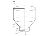
- a punch 200 having a shape as shown in FIG. 19 is used.
- the punch 200 has an inclined portion P1 having a tool inclined surface s1, a vertical wall surface s2 extending along the pushing direction from the tool inclined surface s1, and a pressing surface s3 orthogonal to the vertical wall surface s2. It has a protrusion P2 that protrudes in the direction.
- a cross-sectional shape passing through the central axis of the punch 200 is the same as in FIG.
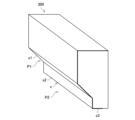
- the shear of the shear cutting machine may have the shape of a shear 300 as shown in FIG. 20, for example.
- the shear 300 has an inclined portion P1 having a tool inclined surface s1, a vertical wall surface s2 extending along the pushing direction from the tool inclined surface s1, and a pressing surface s3 perpendicular to the vertical wall surface s2. It has a protrusion P2 that protrudes in the direction.
- the side shape of shear 300 is the same as in FIG.
- the blade portion of at least one of the first tool and the second tool of the cutting device according to this embodiment has a cross-sectional shape as shown in FIG.
- both the first tool and the second tool have a cross section as shown in FIG. It suffices if it has a shaped blade.
- both the first tool and the second tool have blades with cross-sectional shapes as shown in FIG. You may have
- the multilayer material was a plated steel sheet, but the multilayer material may be formed by coating the surface of the base material with a coating material.
- the base material may be not only a steel plate but also other metal materials, and the coating material may be Zn, Al or an alloy thereof, an oxide film, a coating material, a resin material, or the like.
- the multi-layer material may be a coated steel sheet obtained by coating the surface of a metal material as a base material, or may be a film-laminated steel sheet obtained by laminating a film on a steel sheet.
- the coating material may be a clad material.
- the multilayer material may be a Ni-clad copper material or the like having a Cu plate as a base material and a Ni plate as a coating material.
- the coating material that constitutes the multilayer material is not limited to only one layer, and may be multiple layers.
- the surface of the plated steel sheet described above may be subjected to chemical conversion treatment, painting, lamination, or the like.
- the multi-layer material may be a multi-layer material in which a resin material such as plastic is used as a base material and a metal material such as Cu, Cr, Ag, Au, Pt, etc. is used as a coating material.
- a resin material such as plastic coated with metal
- the electrical conductivity of the end face is lost.
- the exposed ratio of the resin is high, it becomes easy to be charged, and there is concern about the generation of sparks. Therefore, by making the cut end face of such a resin material the same shape as the cut end face of the multilayer material according to the present embodiment, it is possible to improve the electrical conductivity of the cut end face and prevent electrification. Become.
- the purpose required when cutting is different depending on the combination with the coating material and the application.
- the same shape as the cut end surface of the multilayer material according to the present embodiment it is possible to improve the corrosion resistance, chemical resistance, etc. of the base material on the cut end surface by the effect of the coating material.
- electrical conductivity, thermal conductivity, magnetism, etc. of a part or the whole of the cut end face can be improved as compared with the conventional cutting method.
- the shape of the cut end surface of the multilayer material the shape of the cut end surface according to this embodiment, it is possible to exhibit the effects obtained by the coating material on the upper and lower surfaces also on the cut end surface.
- the effect obtained by the coating material is not limited to the above examples, and the effect can be exhibited depending on the application of the coating material.
Landscapes
- Engineering & Computer Science (AREA)
- Mechanical Engineering (AREA)
- Shearing Machines (AREA)
- Nonmetal Cutting Devices (AREA)
- Knives (AREA)
Priority Applications (6)
| Application Number | Priority Date | Filing Date | Title |
|---|---|---|---|
| KR1020247014340A KR20240073939A (ko) | 2021-10-05 | 2022-08-22 | 절단 장치 및 복층재 |
| CN202280066627.XA CN118076451A (zh) | 2021-10-05 | 2022-08-22 | 切割装置和多层材料 |
| MX2024003991A MX2024003991A (es) | 2021-10-05 | 2022-08-22 | Dispositivo de corte y material multicapas. |
| EP22878212.4A EP4414111A4 (en) | 2021-10-05 | 2022-08-22 | CUTTING DEVICE AND MULTI-LAYER MATERIAL |
| JP2023552728A JPWO2023058341A1 (https=) | 2021-10-05 | 2022-08-22 | |
| US18/696,897 US20240390998A1 (en) | 2021-10-05 | 2022-08-22 | Cutting apparatus and multi-layered material |
Applications Claiming Priority (2)
| Application Number | Priority Date | Filing Date | Title |
|---|---|---|---|
| JP2021-164173 | 2021-10-05 | ||
| JP2021164173 | 2021-10-05 |
Publications (1)
| Publication Number | Publication Date |
|---|---|
| WO2023058341A1 true WO2023058341A1 (ja) | 2023-04-13 |
Family
ID=85803372
Family Applications (1)
| Application Number | Title | Priority Date | Filing Date |
|---|---|---|---|
| PCT/JP2022/031527 Ceased WO2023058341A1 (ja) | 2021-10-05 | 2022-08-22 | 切断装置及び複層材 |
Country Status (8)
| Country | Link |
|---|---|
| US (1) | US20240390998A1 (https=) |
| EP (1) | EP4414111A4 (https=) |
| JP (1) | JPWO2023058341A1 (https=) |
| KR (1) | KR20240073939A (https=) |
| CN (1) | CN118076451A (https=) |
| MX (1) | MX2024003991A (https=) |
| TW (1) | TW202327764A (https=) |
| WO (1) | WO2023058341A1 (https=) |
Citations (7)
| Publication number | Priority date | Publication date | Assignee | Title |
|---|---|---|---|---|
| JPS58186514A (ja) * | 1982-04-20 | 1983-10-31 | Hitachi Cable Ltd | 面取付きスリツト法 |
| JPS58173426U (ja) * | 1982-05-14 | 1983-11-19 | 日立電線株式会社 | かえり無しスリツト装置の回転カツタ |
| JPS6250013U (https=) | 1985-08-08 | 1987-03-27 | ||
| JP2001079719A (ja) * | 1999-09-10 | 2001-03-27 | Fuji Photo Film Co Ltd | 金属板加工装置、金属板加工方法及び金属板 |
| JP2004034183A (ja) | 2002-07-01 | 2004-02-05 | Denki Shizai Kk | 鋼板の切断方法及び切断した鋼板 |
| JP2018075600A (ja) * | 2016-11-09 | 2018-05-17 | 日新製鋼株式会社 | 表面処理鋼板の端面の構成、表面処理鋼板の部材、および表面処理鋼板の部材の製造方法 |
| JP2020116724A (ja) * | 2019-03-29 | 2020-08-06 | 日鉄日新製鋼株式会社 | 表面処理金属部材の製造方法および表面処理金属部材 |
Family Cites Families (5)
| Publication number | Priority date | Publication date | Assignee | Title |
|---|---|---|---|---|
| JPS6250013A (ja) | 1985-08-30 | 1987-03-04 | Kawasaki Steel Corp | 棒鋼圧延機の冷却液遮断装置 |
| SU1433654A1 (ru) * | 1986-12-08 | 1988-10-30 | Магнитогорский горно-металлургический институт им.Г.И.Носова | Способ обрезки кромок металлических полос |
| US20060005672A1 (en) * | 2004-07-07 | 2006-01-12 | Chapman Gregory M | Blades, saws, and methods for cutting microfeature workpieces |
| US20190364868A1 (en) * | 2018-06-04 | 2019-12-05 | Joshua Israel Garner | Flat-Tipped End Farrier Shears |
| JP7155784B2 (ja) * | 2018-09-13 | 2022-10-19 | 日本製鉄株式会社 | 表面処理鋼板の切断方法 |
-
2022
- 2022-08-22 TW TW111131444A patent/TW202327764A/zh unknown
- 2022-08-22 EP EP22878212.4A patent/EP4414111A4/en active Pending
- 2022-08-22 JP JP2023552728A patent/JPWO2023058341A1/ja active Pending
- 2022-08-22 CN CN202280066627.XA patent/CN118076451A/zh active Pending
- 2022-08-22 WO PCT/JP2022/031527 patent/WO2023058341A1/ja not_active Ceased
- 2022-08-22 KR KR1020247014340A patent/KR20240073939A/ko active Pending
- 2022-08-22 MX MX2024003991A patent/MX2024003991A/es unknown
- 2022-08-22 US US18/696,897 patent/US20240390998A1/en active Pending
Patent Citations (7)
| Publication number | Priority date | Publication date | Assignee | Title |
|---|---|---|---|---|
| JPS58186514A (ja) * | 1982-04-20 | 1983-10-31 | Hitachi Cable Ltd | 面取付きスリツト法 |
| JPS58173426U (ja) * | 1982-05-14 | 1983-11-19 | 日立電線株式会社 | かえり無しスリツト装置の回転カツタ |
| JPS6250013U (https=) | 1985-08-08 | 1987-03-27 | ||
| JP2001079719A (ja) * | 1999-09-10 | 2001-03-27 | Fuji Photo Film Co Ltd | 金属板加工装置、金属板加工方法及び金属板 |
| JP2004034183A (ja) | 2002-07-01 | 2004-02-05 | Denki Shizai Kk | 鋼板の切断方法及び切断した鋼板 |
| JP2018075600A (ja) * | 2016-11-09 | 2018-05-17 | 日新製鋼株式会社 | 表面処理鋼板の端面の構成、表面処理鋼板の部材、および表面処理鋼板の部材の製造方法 |
| JP2020116724A (ja) * | 2019-03-29 | 2020-08-06 | 日鉄日新製鋼株式会社 | 表面処理金属部材の製造方法および表面処理金属部材 |
Non-Patent Citations (1)
| Title |
|---|
| See also references of EP4414111A4 |
Also Published As
| Publication number | Publication date |
|---|---|
| TW202533892A (zh) | 2025-09-01 |
| TW202327764A (zh) | 2023-07-16 |
| KR20240073939A (ko) | 2024-05-27 |
| JPWO2023058341A1 (https=) | 2023-04-13 |
| US20240390998A1 (en) | 2024-11-28 |
| CN118076451A (zh) | 2024-05-24 |
| EP4414111A4 (en) | 2025-03-12 |
| EP4414111A1 (en) | 2024-08-14 |
| MX2024003991A (es) | 2024-04-25 |
Similar Documents
| Publication | Publication Date | Title |
|---|---|---|
| US7922067B2 (en) | Tailor welded blank assembly and method | |
| RU2454291C2 (ru) | Способ изготовления проволочной ленты, состоящей из большого числа расположенных параллельно друг другу проволочных нитей, а также проволочная лента, изготовленная этим способом | |
| US7316849B2 (en) | Semi-finished product made out of a ductile material with breaking areas | |
| WO2024116774A1 (ja) | 非晶質合金片の製造方法 | |
| WO2023058341A1 (ja) | 切断装置及び複層材 | |
| JP7299524B2 (ja) | 切断方法 | |
| WO2023145228A1 (ja) | アモルファス合金箔のせん断加工法 | |
| TWI921203B (zh) | 切斷裝置及多層材 | |
| JP2023016506A (ja) | 加工材の製造方法 | |
| JP7155784B2 (ja) | 表面処理鋼板の切断方法 | |
| HK40105792A (zh) | 切割装置和多层材料 | |
| TWI890296B (zh) | 切斷裝置、切斷方法及多層材 | |
| JP7502620B2 (ja) | 加工材の製造方法 | |
| JP7135767B2 (ja) | 表面処理鋼板の切断方法 | |
| WO2023127479A1 (ja) | 加工装置、金属製部材の製造方法、及び金属製部材 | |
| JP5024980B2 (ja) | ステンレス鋼製スパイラル・スクリューの製造方法 | |
| JP2019030899A (ja) | 剪断加工方法 | |
| JP7678380B2 (ja) | 加工材の製造方法及び加工材 | |
| JP2829622B2 (ja) | 積層金属板のせん断法 | |
| CN113787315A (zh) | 高温钢板的在线热纵切方法 | |
| CN114559088B (zh) | 一种钢塑复合打包带加工的圆盘剪刀及其使用方法 | |
| JP7248891B2 (ja) | 表面処理金属部材の製造方法 | |
| JP2010179333A (ja) | 冷延鋼板の製造方法 | |
| JP2010089111A (ja) | 冷延鋼板の製造方法および製造設備 | |
| JP2000343145A (ja) | ロータリーブランキング用ロール金型およびロータリーブランキング方法 |
Legal Events
| Date | Code | Title | Description |
|---|---|---|---|
| 121 | Ep: the epo has been informed by wipo that ep was designated in this application |
Ref document number: 22878212 Country of ref document: EP Kind code of ref document: A1 |
|
| WWE | Wipo information: entry into national phase |
Ref document number: 2023552728 Country of ref document: JP |
|
| WWE | Wipo information: entry into national phase |
Ref document number: 18696897 Country of ref document: US |
|
| WWE | Wipo information: entry into national phase |
Ref document number: 2401002108 Country of ref document: TH |
|
| WWE | Wipo information: entry into national phase |
Ref document number: 202280066627.X Country of ref document: CN |
|
| WWE | Wipo information: entry into national phase |
Ref document number: 202417027616 Country of ref document: IN Ref document number: 12024550818 Country of ref document: PH |
|
| ENP | Entry into the national phase |
Ref document number: 20247014340 Country of ref document: KR Kind code of ref document: A |
|
| WWE | Wipo information: entry into national phase |
Ref document number: 2022878212 Country of ref document: EP |
|
| NENP | Non-entry into the national phase |
Ref country code: DE |
|
| ENP | Entry into the national phase |
Ref document number: 2022878212 Country of ref document: EP Effective date: 20240506 |