WO2023053379A1 - 摺動部材 - Google Patents
摺動部材 Download PDFInfo
- Publication number
- WO2023053379A1 WO2023053379A1 PCT/JP2021/036226 JP2021036226W WO2023053379A1 WO 2023053379 A1 WO2023053379 A1 WO 2023053379A1 JP 2021036226 W JP2021036226 W JP 2021036226W WO 2023053379 A1 WO2023053379 A1 WO 2023053379A1
- Authority
- WO
- WIPO (PCT)
- Prior art keywords
- band
- peak intensity
- area
- ratio
- less
- Prior art date
- Legal status (The legal status is an assumption and is not a legal conclusion. Google has not performed a legal analysis and makes no representation as to the accuracy of the status listed.)
- Ceased
Links
Images



Classifications
-
- C—CHEMISTRY; METALLURGY
- C23—COATING METALLIC MATERIAL; COATING MATERIAL WITH METALLIC MATERIAL; CHEMICAL SURFACE TREATMENT; DIFFUSION TREATMENT OF METALLIC MATERIAL; COATING BY VACUUM EVAPORATION, BY SPUTTERING, BY ION IMPLANTATION OR BY CHEMICAL VAPOUR DEPOSITION, IN GENERAL; INHIBITING CORROSION OF METALLIC MATERIAL OR INCRUSTATION IN GENERAL
- C23C—COATING METALLIC MATERIAL; COATING MATERIAL WITH METALLIC MATERIAL; SURFACE TREATMENT OF METALLIC MATERIAL BY DIFFUSION INTO THE SURFACE, BY CHEMICAL CONVERSION OR SUBSTITUTION; COATING BY VACUUM EVAPORATION, BY SPUTTERING, BY ION IMPLANTATION OR BY CHEMICAL VAPOUR DEPOSITION, IN GENERAL
- C23C14/00—Coating by vacuum evaporation, by sputtering or by ion implantation of the coating forming material
- C23C14/06—Coating by vacuum evaporation, by sputtering or by ion implantation of the coating forming material characterised by the coating material
- C23C14/0605—Carbon
- C23C14/0611—Diamond
-
- C—CHEMISTRY; METALLURGY
- C01—INORGANIC CHEMISTRY
- C01B—NON-METALLIC ELEMENTS; COMPOUNDS THEREOF; METALLOIDS OR COMPOUNDS THEREOF NOT COVERED BY SUBCLASS C01C
- C01B32/00—Carbon; Compounds thereof
- C01B32/05—Preparation or purification of carbon not covered by groups C01B32/15, C01B32/20, C01B32/25, C01B32/30
-
- C—CHEMISTRY; METALLURGY
- C23—COATING METALLIC MATERIAL; COATING MATERIAL WITH METALLIC MATERIAL; CHEMICAL SURFACE TREATMENT; DIFFUSION TREATMENT OF METALLIC MATERIAL; COATING BY VACUUM EVAPORATION, BY SPUTTERING, BY ION IMPLANTATION OR BY CHEMICAL VAPOUR DEPOSITION, IN GENERAL; INHIBITING CORROSION OF METALLIC MATERIAL OR INCRUSTATION IN GENERAL
- C23C—COATING METALLIC MATERIAL; COATING MATERIAL WITH METALLIC MATERIAL; SURFACE TREATMENT OF METALLIC MATERIAL BY DIFFUSION INTO THE SURFACE, BY CHEMICAL CONVERSION OR SUBSTITUTION; COATING BY VACUUM EVAPORATION, BY SPUTTERING, BY ION IMPLANTATION OR BY CHEMICAL VAPOUR DEPOSITION, IN GENERAL
- C23C14/00—Coating by vacuum evaporation, by sputtering or by ion implantation of the coating forming material
- C23C14/06—Coating by vacuum evaporation, by sputtering or by ion implantation of the coating forming material characterised by the coating material
- C23C14/0605—Carbon
-
- C—CHEMISTRY; METALLURGY
- C23—COATING METALLIC MATERIAL; COATING MATERIAL WITH METALLIC MATERIAL; CHEMICAL SURFACE TREATMENT; DIFFUSION TREATMENT OF METALLIC MATERIAL; COATING BY VACUUM EVAPORATION, BY SPUTTERING, BY ION IMPLANTATION OR BY CHEMICAL VAPOUR DEPOSITION, IN GENERAL; INHIBITING CORROSION OF METALLIC MATERIAL OR INCRUSTATION IN GENERAL
- C23C—COATING METALLIC MATERIAL; COATING MATERIAL WITH METALLIC MATERIAL; SURFACE TREATMENT OF METALLIC MATERIAL BY DIFFUSION INTO THE SURFACE, BY CHEMICAL CONVERSION OR SUBSTITUTION; COATING BY VACUUM EVAPORATION, BY SPUTTERING, BY ION IMPLANTATION OR BY CHEMICAL VAPOUR DEPOSITION, IN GENERAL
- C23C14/00—Coating by vacuum evaporation, by sputtering or by ion implantation of the coating forming material
- C23C14/22—Coating by vacuum evaporation, by sputtering or by ion implantation of the coating forming material characterised by the process of coating
- C23C14/24—Vacuum evaporation
- C23C14/32—Vacuum evaporation by explosion; by evaporation and subsequent ionisation of the vapours, e.g. ion-plating
- C23C14/325—Electric arc evaporation
-
- C—CHEMISTRY; METALLURGY
- C23—COATING METALLIC MATERIAL; COATING MATERIAL WITH METALLIC MATERIAL; CHEMICAL SURFACE TREATMENT; DIFFUSION TREATMENT OF METALLIC MATERIAL; COATING BY VACUUM EVAPORATION, BY SPUTTERING, BY ION IMPLANTATION OR BY CHEMICAL VAPOUR DEPOSITION, IN GENERAL; INHIBITING CORROSION OF METALLIC MATERIAL OR INCRUSTATION IN GENERAL
- C23C—COATING METALLIC MATERIAL; COATING MATERIAL WITH METALLIC MATERIAL; SURFACE TREATMENT OF METALLIC MATERIAL BY DIFFUSION INTO THE SURFACE, BY CHEMICAL CONVERSION OR SUBSTITUTION; COATING BY VACUUM EVAPORATION, BY SPUTTERING, BY ION IMPLANTATION OR BY CHEMICAL VAPOUR DEPOSITION, IN GENERAL
- C23C28/00—Coating for obtaining at least two superposed coatings either by methods not provided for in a single one of groups C23C2/00 - C23C26/00 or by combinations of methods provided for in subclasses C23C and C25C or C25D
- C23C28/30—Coatings combining at least one metallic layer and at least one inorganic non-metallic layer
- C23C28/32—Coatings combining at least one metallic layer and at least one inorganic non-metallic layer including at least one pure metallic layer
-
- C—CHEMISTRY; METALLURGY
- C23—COATING METALLIC MATERIAL; COATING MATERIAL WITH METALLIC MATERIAL; CHEMICAL SURFACE TREATMENT; DIFFUSION TREATMENT OF METALLIC MATERIAL; COATING BY VACUUM EVAPORATION, BY SPUTTERING, BY ION IMPLANTATION OR BY CHEMICAL VAPOUR DEPOSITION, IN GENERAL; INHIBITING CORROSION OF METALLIC MATERIAL OR INCRUSTATION IN GENERAL
- C23C—COATING METALLIC MATERIAL; COATING MATERIAL WITH METALLIC MATERIAL; SURFACE TREATMENT OF METALLIC MATERIAL BY DIFFUSION INTO THE SURFACE, BY CHEMICAL CONVERSION OR SUBSTITUTION; COATING BY VACUUM EVAPORATION, BY SPUTTERING, BY ION IMPLANTATION OR BY CHEMICAL VAPOUR DEPOSITION, IN GENERAL
- C23C28/00—Coating for obtaining at least two superposed coatings either by methods not provided for in a single one of groups C23C2/00 - C23C26/00 or by combinations of methods provided for in subclasses C23C and C25C or C25D
- C23C28/30—Coatings combining at least one metallic layer and at least one inorganic non-metallic layer
- C23C28/32—Coatings combining at least one metallic layer and at least one inorganic non-metallic layer including at least one pure metallic layer
- C23C28/322—Coatings combining at least one metallic layer and at least one inorganic non-metallic layer including at least one pure metallic layer only coatings of metal elements only
-
- C—CHEMISTRY; METALLURGY
- C23—COATING METALLIC MATERIAL; COATING MATERIAL WITH METALLIC MATERIAL; CHEMICAL SURFACE TREATMENT; DIFFUSION TREATMENT OF METALLIC MATERIAL; COATING BY VACUUM EVAPORATION, BY SPUTTERING, BY ION IMPLANTATION OR BY CHEMICAL VAPOUR DEPOSITION, IN GENERAL; INHIBITING CORROSION OF METALLIC MATERIAL OR INCRUSTATION IN GENERAL
- C23C—COATING METALLIC MATERIAL; COATING MATERIAL WITH METALLIC MATERIAL; SURFACE TREATMENT OF METALLIC MATERIAL BY DIFFUSION INTO THE SURFACE, BY CHEMICAL CONVERSION OR SUBSTITUTION; COATING BY VACUUM EVAPORATION, BY SPUTTERING, BY ION IMPLANTATION OR BY CHEMICAL VAPOUR DEPOSITION, IN GENERAL
- C23C28/00—Coating for obtaining at least two superposed coatings either by methods not provided for in a single one of groups C23C2/00 - C23C26/00 or by combinations of methods provided for in subclasses C23C and C25C or C25D
- C23C28/30—Coatings combining at least one metallic layer and at least one inorganic non-metallic layer
- C23C28/34—Coatings combining at least one metallic layer and at least one inorganic non-metallic layer including at least one inorganic non-metallic material layer, e.g. metal carbide, nitride, boride, silicide layer and their mixtures, enamels, phosphates and sulphates
-
- C—CHEMISTRY; METALLURGY
- C23—COATING METALLIC MATERIAL; COATING MATERIAL WITH METALLIC MATERIAL; CHEMICAL SURFACE TREATMENT; DIFFUSION TREATMENT OF METALLIC MATERIAL; COATING BY VACUUM EVAPORATION, BY SPUTTERING, BY ION IMPLANTATION OR BY CHEMICAL VAPOUR DEPOSITION, IN GENERAL; INHIBITING CORROSION OF METALLIC MATERIAL OR INCRUSTATION IN GENERAL
- C23C—COATING METALLIC MATERIAL; COATING MATERIAL WITH METALLIC MATERIAL; SURFACE TREATMENT OF METALLIC MATERIAL BY DIFFUSION INTO THE SURFACE, BY CHEMICAL CONVERSION OR SUBSTITUTION; COATING BY VACUUM EVAPORATION, BY SPUTTERING, BY ION IMPLANTATION OR BY CHEMICAL VAPOUR DEPOSITION, IN GENERAL
- C23C28/00—Coating for obtaining at least two superposed coatings either by methods not provided for in a single one of groups C23C2/00 - C23C26/00 or by combinations of methods provided for in subclasses C23C and C25C or C25D
- C23C28/30—Coatings combining at least one metallic layer and at least one inorganic non-metallic layer
- C23C28/34—Coatings combining at least one metallic layer and at least one inorganic non-metallic layer including at least one inorganic non-metallic material layer, e.g. metal carbide, nitride, boride, silicide layer and their mixtures, enamels, phosphates and sulphates
- C23C28/343—Coatings combining at least one metallic layer and at least one inorganic non-metallic layer including at least one inorganic non-metallic material layer, e.g. metal carbide, nitride, boride, silicide layer and their mixtures, enamels, phosphates and sulphates with at least one DLC or an amorphous carbon based layer, the layer being doped or not
-
- F—MECHANICAL ENGINEERING; LIGHTING; HEATING; WEAPONS; BLASTING
- F02—COMBUSTION ENGINES; HOT-GAS OR COMBUSTION-PRODUCT ENGINE PLANTS
- F02F—CYLINDERS, PISTONS OR CASINGS, FOR COMBUSTION ENGINES; ARRANGEMENTS OF SEALINGS IN COMBUSTION ENGINES
- F02F5/00—Piston rings, e.g. associated with piston crown
-
- F—MECHANICAL ENGINEERING; LIGHTING; HEATING; WEAPONS; BLASTING
- F16—ENGINEERING ELEMENTS AND UNITS; GENERAL MEASURES FOR PRODUCING AND MAINTAINING EFFECTIVE FUNCTIONING OF MACHINES OR INSTALLATIONS; THERMAL INSULATION IN GENERAL
- F16J—PISTONS; CYLINDERS; SEALINGS
- F16J9/00—Piston-rings, e.g. non-metallic piston-rings, seats therefor; Ring sealings of similar construction
- F16J9/26—Piston-rings, e.g. non-metallic piston-rings, seats therefor; Ring sealings of similar construction characterised by the use of particular materials
-
- C—CHEMISTRY; METALLURGY
- C01—INORGANIC CHEMISTRY
- C01B—NON-METALLIC ELEMENTS; COMPOUNDS THEREOF; METALLOIDS OR COMPOUNDS THEREOF NOT COVERED BY SUBCLASS C01C
- C01B32/00—Carbon; Compounds thereof
- C01B32/25—Diamond
-
- G—PHYSICS
- G01—MEASURING; TESTING
- G01N—INVESTIGATING OR ANALYSING MATERIALS BY DETERMINING THEIR CHEMICAL OR PHYSICAL PROPERTIES
- G01N21/00—Investigating or analysing materials by the use of optical means, i.e. using sub-millimetre waves, infrared, visible or ultraviolet light
- G01N21/62—Systems in which the material investigated is excited whereby it emits light or causes a change in wavelength of the incident light
- G01N21/63—Systems in which the material investigated is excited whereby it emits light or causes a change in wavelength of the incident light optically excited
- G01N21/65—Raman scattering
Definitions
- the present invention relates to sliding members that are mainly used in internal combustion engines.
- a DLC (diamond-like carbon) film is an amorphous structure (amorphous structure) film in which sp 2 bonds of carbon atoms corresponding to a graphite structure and sp 3 bonds of carbon atoms corresponding to a diamond structure are mixed. By adjusting the ratio of both binding components, DLC coatings with different properties can be formed.
- DLC coatings which have excellent wear resistance and sliding properties, are used as sliding members for internal combustion engines, which have a severe sliding environment.
- Sliding members for internal combustion engines include piston rings, cylinder liners, camshafts, and the like.
- the DLC film in which the S band derived from the sp 3 bond is measured is heat resistant. It is disclosed that the hardness is improved and the hardness is high.
- the present inventors are aware of the fact that the DLC coating of a DLC-treated sliding member may wear out due to insufficient wear resistance. That is, the conventionally disclosed sliding member having a DLC coating has a problem that the wear resistance (abrasive wear resistance) is not sufficient when foreign matter such as carbon sludge is mixed. Sliding with foreign matter such as carbon sludge intervening may cause fine cracks on the sliding surface of the DLC coating.
- the present invention has been made in view of the above problems, and provides a sliding member that has wear resistance (abrasive wear resistance) even in an environment where foreign matter such as carbon sludge is present.
- the present inventors have made repeated studies to solve the above problems, and found that the DLC coating is capable of measuring the S band derived from sp 3 bonds in addition to the G band derived from the graphite structure and the D band derived from defects in the graphite structure.
- the inventors have found that a sliding member having a DLC coating on the outer peripheral sliding surface, which satisfies a specific relationship between these bands, can solve the above problems, and completed the present invention.
- the presence of the S band has a significant effect on the wear resistance of the DLC coating.
- the abrasion resistance of the DLC film was improved by setting the peak intensity ratio and area ratio of the S band, D band, and G band within specific ranges.
- the present invention relates to a sliding member having a DLC coating on its outer peripheral sliding surface,
- the DLC coating has an S band with a peak near 1150 cm ⁇ 1 , a D band with a peak near 1400 cm ⁇ 1 , and a G band with a peak near 1580 cm ⁇ 1 in the Raman spectrum, and the S band
- the ratio of the peak intensity of the G band to the peak intensity of the G band (I G /I S ) is 5.6 or less, and the ratio of the peak intensity area of the G band to the peak intensity area of the S band (A G /A S ) is 4 .7 or less.
- the DLC film has a ratio of the peak intensity of the G band to the sum of the peak intensity of the S band and the intensity peak of the D band (I G /I S+D ) of 1.1 or less, and the peak intensity area of the S band and the peak intensity area of the D band (A G /A S+D ) is preferably 0.76 or less.
- the ratio of the peak intensity of the G band to the sum of the peak intensity of the S band, the peak intensity of the D band, and the peak intensity of the G band (I G /I S+D+G ) is 0.50 or less, and the peak intensity of the S band
- the ratio of the peak intensity area of the G band to the sum of the area, the peak intensity area of the D band, and the peak intensity area of the G band (A G /A S+D+G ) is preferably 0.43 or less.
- the ratio of the peak intensity of the D band to the sum of the peak intensity of the S band and the peak intensity of the G band is 0.68 or more, and the peak intensity area of the S band and the peak of the G band
- the ratio of the peak intensity area of the D band to the sum of the intensity areas (A D /A S+G ) is preferably 0.9 or more.
- the ratio of the peak intensity of the D band to the sum of the peak intensity of the S band, the peak intensity of the D band, and the peak intensity of the G band (I D /I S+D+G ) is 0.41 or more, and the peak intensity of the S band
- the ratio of the peak intensity area of the D band to the sum of the area, the peak intensity area of the D band, and the peak intensity area of the G band (A D /A S+D+G ) is preferably 0.48 or more.
- the ratio of the peak intensity of the S band to the sum of the peak intensity of the D band and the peak intensity of the G band is 0.1 or more, and the area of the peak intensity of the D band and the peak intensity of the G band
- the ratio of the peak intensity area of the S band to the sum of the areas (A S /A D+G ) is preferably 0.1 or more.
- the ratio of the peak intensity of the S band to the sum of the peak intensity of the S band, the peak intensity of the D band, and the peak intensity of the G band (I S /I S+D+G ) is 0.09 or more, and the peak intensity of the S band
- the ratio of the peak intensity area of the S band to the sum of the area, the peak intensity area of the D band, and the peak intensity area of the G band (A S /A S+D+G ) is preferably 0.09 or more.
- the DLC coating preferably does not substantially contain hydrogen, and the hydrogen content is preferably 0.5 at % or less, and the sliding member is preferably a piston ring.
- a sliding member coated with a DLC film which is less susceptible to microfracture on the sliding surface due to the development of cracks and can suppress an increase in abrasive wear.
- FIG. 2 shows a schematic cross-sectional view of a piston ring in which a DLC coating having a base layer is formed on a piston ring base material. It is a schematic diagram which shows the outline
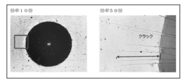
- 4 is a laser microscope image showing the results of a Rockwell indentation test on the DLC coating of Example 1 (photograph substituting for drawing). 4 is a laser microscope image showing the results of a Rockwell indentation test on the DLC coating of Comparative Example 1 (photograph substituting for drawing).
- An embodiment of the present invention is a sliding member having a DLC coating on the outer peripheral sliding surface.
- the sliding member may be used in internal combustion engines or may be used in other than internal combustion engines, but it is particularly suitable for use in internal combustion engines.
- Sliding members used in internal combustion engines include piston rings, cylinder liners, camshafts, etc.
- description will be made using a piston ring as a typical example of the sliding member.
- the DLC coating of the sliding member has an S band with a peak around 1150 cm ⁇ 1 , a D band with a peak around 1400 cm ⁇ 1 , and a G band with a peak around 1580 cm ⁇ 1 in the Raman spectrum. and the ratio of the G-band peak intensity to the S-band peak intensity (I G /I S ) is 5.6 or less, and the ratio of the G-band peak intensity area to the S-band peak intensity area (A G /A S ) is 4.7 or less.
- the S band in the Raman spectroscopy spectrum is the band derived from sp3 bonding.
- the G band is a band derived from the graphite structure, and the D band is a band derived from defects in the graphite structure.
- the present inventors found that these three bands exist in the Raman spectroscopic spectrum, the ratio of the peak intensity of the G band to the peak intensity of the S band (I G /I S ) is 5.6 or less, and the S band When the ratio of the peak intensity area of the G band to the peak intensity area of the G band (A G /A S ) is 4.7 or less, microfractures on the sliding surface due to the progress of cracks in the DLC film are unlikely to occur, and abrasive wear It was found that the increase can be suppressed. If no S-band is present, the abrasion resistance is insufficient.
- the peak intensity ratio (I G /I S ) is preferably 5.0 or less, more preferably 4.0 or less. Although the lower limit is not particularly limited, it may be 2.5 or more. Also, the peak intensity area ratio (A G /A S ) is preferably 4.1 or less, more preferably 3.0 or less. Although the lower limit is not particularly limited, it may be 1.6 or more.
- the ratio of the peak intensity of the G band to the sum of the peak intensity of the S band and the peak intensity of the D band is 1.1 or less, and the area of the peak intensity of the S band and the peak of the D band
- the ratio of the peak intensity area of the G band to the sum of the intensity areas (A G /A S+D ) is preferably 0.76 or less.
- the lower limit of (I G /I S+D ) is not particularly limited, but may be 0.4 or more, and the lower limit of (A G /A S+D ) is not particularly limited, but may be 0.2 or more.
- the ratio of the peak intensity of the G band to the sum of the peak intensity of the S band, the peak intensity of the D band, and the peak intensity of the G band is 0.50 or less
- the peak intensity of the S band The ratio of the peak intensity area of the G band to the sum of the area, the peak intensity area of the D band, and the peak intensity area of the G band (A G /A S+D+G ) is preferably 0.43 or less.
- the lower limit of (I G /I S+D+G ) is not particularly limited, but may be 0.3 or more
- the lower limit of (A G /A S+D+G ) is not particularly limited, but may be 0.19 or more. Satisfying the above range is preferable because microfractures on the sliding surface due to the development of cracks in the DLC coating are less likely to occur, and an increase in abrasive wear can be suppressed.
- the ratio of the peak intensity of the D band to the sum of the peak intensity of the S band and the peak intensity of the G band is 0.68 or more, and the peak intensity area of the S band and the peak of the G band
- the ratio of the peak intensity area of the D band to the sum of the intensity areas (A D /A S+G ) is preferably 0.9 or more.
- the upper limit of (I D /I S+G ) is not particularly limited, but may be 1.4 or less, and the upper limit of ( AD /A S+G ) is not particularly limited, but may be 2.3 or less.
- the ratio of the peak intensity of the D band to the sum of the peak intensity of the S band, the peak intensity of the D band, and the peak intensity of the G band is 0.41 or more, and the peak intensity of the S band
- the ratio of the peak intensity area of the D band to the sum of the area, the peak intensity area of the D band, and the peak intensity area of the G band is preferably 0.48 or more.
- the upper limit of (I D /I S+D+G ) is not particularly limited, but may be 0.6 or less, and the upper limit of (A D /A S+D+G ) is not particularly limited, but may be 0.7 or less. Satisfying the above range is preferable because microfractures on the sliding surface due to the development of cracks in the DLC coating are less likely to occur, and an increase in abrasive wear can be suppressed.
- the ratio of the peak intensity of the S band to the sum of the peak intensity of the D band and the peak intensity of the G band is 0.1 or more, and the peak intensity area of the D band and the peak of the G band
- the ratio of the peak intensity area of the S band to the sum of the intensity areas (A S /A D+G ) is preferably 0.1 or more.
- the upper limit of (I S /I D+G ) is not particularly limited, but may be 0.15 or less, and the upper limit of (A S /A D+G ) is not particularly limited, but may be 0.14 or less.
- the ratio of the peak intensity of the S band to the sum of the peak intensity of the S band, the peak intensity of the D band, and the peak intensity of the G band is 0.09 or more
- the peak intensity of the S band The ratio of the peak intensity area of the S band to the sum of the area, the peak intensity area of the D band, and the peak intensity area of the G band (A S /A S+D+G ) is preferably 0.09 or more.
- the upper limit of (I S /I S+D+G ) is not particularly limited, but may be 0.13 or less, and the upper limit of (A S /A S+D+G ) is not particularly limited, but may be 0.13 or less. Satisfying the above range is preferable because microfractures on the sliding surface due to the development of cracks in the DLC coating are less likely to occur, and an increase in abrasive wear can be suppressed.
- the peak intensity and peak intensity area of the S band, D band and G band of the Raman spectroscopic spectrum can be set to desired values by adjusting the manufacturing method of the DLC film. More specifically, when forming a DLC coating using a filtered cathode vacuum arc (FCVA) method, the applied pulse bias voltage is, for example, -500 V to -2500 V, preferably - 700V to -2500V. In addition, a desired value can be obtained by adjusting the substrate temperature, chamber pressure (vacuum degree), arc current, target purity, etc. during the formation of the DLC film.
- FCVA filtered cathode vacuum arc
- a specific embodiment of the present invention will be described below, taking as an example the case where the sliding member is a piston ring.
- a piston ring 10 shown in FIG. 1 is mounted in a piston ring groove (not shown) formed in a piston, and reciprocates while sliding on the inner peripheral surface of a cylinder bore (not shown) by the reciprocating motion of the piston.
- the piston ring 10 may be used as a top ring, a second ring, or an oil ring.
- the oil ring body When applied to an oil ring, the oil ring body of a two-piece configuration oil ring consisting of an oil ring body and a coil expander, and a three-piece configuration consisting of two segments (also called side rails) and an expander spacer. It can be applied to any segment of the oil ring.
- the piston ring is attached to an aluminum alloy piston and used as a piston ring for a cast iron cylinder bore, but the material of the piston and cylinder is not limited to these.
- the material of the piston ring base material 11 is not particularly limited as long as it is a material conventionally used as a piston ring base material.
- stainless steel, spring steel, etc. are preferably used.
- martensitic stainless steel, silicon chromium steel, etc. are preferably used.
- a piston ring 10 shown in FIG. 1 has an underlying layer 13 containing Cr, Ti, Si, or the like on the smoothed outer peripheral surface of a piston ring base material 11, and has a DLC coating 12 thereon.
- the thickness of the underlying layer 13 is preferably 0.2 ⁇ m or more and 2.0 ⁇ m or less. By setting it as such a film thickness, the adhesiveness of the DLC film 12 and the piston ring base material 11 can be improved more.
- the DLC coating 12 may be formed directly on the smoothed outer peripheral surface of the piston ring base material 11 without providing the base layer 13 .
- the method of smoothing the outer peripheral surface of the piston ring base material 11 before forming the DLC coating 12 is not particularly limited, but it is preferable to perform grinding or buffing to adjust the surface roughness. In addition, when the surface roughness of the outer peripheral surface of the piston ring base material 11 is small, smoothing processing is not necessary.
- the DLC film 12 is preferably selected from aC and taC having a hydrogen content of 0.5 at% or less (substantially hydrogen-free).
- the thickness of the DLC coating 12 is preferably 1 ⁇ m or more, except for the underlying layer.
- the upper limit is not particularly limited, it is preferably 30 ⁇ m or less, and more preferably 20 ⁇ m or less, because an excessively thick film may lead to a decrease in productivity and an increase in cost.
- the DLC film 12 satisfies the parameters of the S-band, D-band and G-band of the Raman spectroscopy spectrum, and the preferred physical properties as a film are described below.
- the nanoindentation hardness of the DLC coating 12 is not particularly limited, it may be 15.0 GPa or more and 30.0 GPa or less, 28.0 GPa or less, or 26.0 GPa or less. Considering wear resistance, it is usually preferable to have a coating with a high hardness. Due to the coating formed on the outer peripheral surface of the ring, the coating may be broken when deformation is involved during assembly work to the piston, etc. Therefore, in the present embodiment, it is preferable to set the hardness in the above range, which is not excessively hard.
- the DLC coating 12 preferably has a Young's modulus of 335 GPa or less, more preferably 310 GPa or less.
- Young's modulus exceeds 335 GPa, when deposits such as carbon sludge or foreign matter such as abrasion powder and dust generated by sliding pass through the surface of the DLC coating, brittle fracture appears in the outermost layer of the DLC coating, increasing wear.
- the lower limit is not particularly limited, when the Young's modulus is 120 GPa or more, peeling inside the film is less likely to occur.
- Nanoindentation hardness and Young's modulus measurement is carried out using a nanoindentation measuring instrument manufactured by Fisher Instruments, model HM-2000, using a Vickers indenter, indentation load of 100 mN, and time to maximum indentation load of 30 s (seconds). was performed under the conditions of Young's modulus is determined from the load-indentation depth curve.
- the measurement value is a total of 4 points at each of 3 positions, the position on the opposite side of the gap of the piston ring and the position 90° on both sides from the gap. An average value of 12 measurements was taken.
- the method for manufacturing the hard carbon coating according to this embodiment is not particularly limited.
- One example is a method of forming a coating using a filtered cathode vacuum arc (FCVA) method.
- FCVA filtered cathode vacuum arc
- the DLC coating may be formed under a single condition, or the DLC coating may be formed by changing the applied pulse bias voltage or forming multiple times without changing the pulse bias voltage. good too.
- the applied pulse bias voltage is higher than usual, for example -500V to -2500V, preferably -700V to -2500V, more preferably -1000V to -2500V.
- Example/Comparative Example With the piston ring base material set in the apparatus, the inside of the apparatus was evacuated to reduce the pressure, and then the base material was heated. After that, by appropriately changing the pulse bias voltage, substrate temperature, chamber pressure (vacuum degree), arc current, target purity, etc., by the FCVA method, Examples 1 to 6 and Comparative Example 1 were obtained. Piston rings with ⁇ 4 hard carbon coatings were obtained. A Raman spectroscopic spectrum was measured under the following conditions for the hard carbon coating of the obtained piston ring. In addition, in the circumferential direction of one piston ring, the measured values are the positions on both sides of the piston ring joint (0°, 360°), the opposite side of the joint, and the positions of 90° on both sides from the joint.
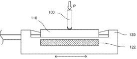
- FIG. 2 shows an outline of the pin-on-plate type reciprocating friction and wear test.
- martensitic stainless steel was used as a piston ring base material having a nominal diameter of 86 mm and a width in the sliding direction of 1.2 mm.
- a piston ring with a machined surface was prepared.
- a piston ring member having a circumference of 20 mm was cut out from each of three positions forming 90° on both sides and the position on the opposite side of the joint of the piston ring, and tested.
- the cut piston ring member was subjected to final finishing, and the surface roughness of the piston ring member after final finishing had a plateau-shaped roughness curve and a maximum height Rz of 1.0 ⁇ m.
- the lower test piece 110 is a material equivalent to JIS FC250, and a plate having a width of 17 mm, a length of 70 mm, and a thickness of 14 mm is prepared to simulate a flake graphite cast iron cylinder bore having a hardness of HRB 100 and carbide precipitation of 3%.
- Surface finishing was performed with #600 emery paper and the surface roughness was 1.2 ⁇ m at maximum height Rz.
- the test conditions for the wear amount measurement test are shown below.
- the sliding surfaces of the upper test piece 100 and the lower test piece 110 were lubricated with 150 ⁇ L (microliters) of engine lubricating oil 0W-20 in which carbon sludge and the like generated during actual engine operation were concentrated for one hour of the test.
- ⁇ Test conditions> ⁇ Stroke: 50mm ⁇ Load: 50N ⁇ Speed: 300 cycles/min ⁇ Temperature of lower test piece: 80°C (using heater 122 for heating lower test piece provided on movable block 120)
- ⁇ Test time 60 minutes
- the wear amount in Table 2 is a relative value with the value of Comparative Example 1 set to 1.
- Example 1 the DLC coatings of Example 1, Examples 3 to 6, and Comparative Example 1 were formed on SKD11 material plates, and Rockwell indentation tests and scratch tests were performed as follows. Table 3 shows the results. In addition, a Rockwell indentation test and a scratch test were performed to evaluate the state of crack generation (length, number of cracks, etc.), and it was confirmed that the more cracks and the longer the cracks, the greater the amount of wear. Further, FIG. 3 shows an electron microscope image of cracks generated on the DLC coating surface in actual machine operation, and FIG. 4 and FIG. Microscopic images are shown.
- Piston ring 11 Piston ring base material 12 DLC coating 13 Base layer 100
- Upper test piece 110 Lower test piece 120 Movable block 122
Landscapes
- Chemical & Material Sciences (AREA)
- Engineering & Computer Science (AREA)
- Mechanical Engineering (AREA)
- Organic Chemistry (AREA)
- Chemical Kinetics & Catalysis (AREA)
- Materials Engineering (AREA)
- Metallurgy (AREA)
- Inorganic Chemistry (AREA)
- General Engineering & Computer Science (AREA)
- Life Sciences & Earth Sciences (AREA)
- General Life Sciences & Earth Sciences (AREA)
- Combustion & Propulsion (AREA)
- Geology (AREA)
- Pistons, Piston Rings, And Cylinders (AREA)
- Health & Medical Sciences (AREA)
- Biochemistry (AREA)
- General Physics & Mathematics (AREA)
- Immunology (AREA)
- Pathology (AREA)
- General Health & Medical Sciences (AREA)
- Nuclear Medicine, Radiotherapy & Molecular Imaging (AREA)
- Analytical Chemistry (AREA)
- Physics & Mathematics (AREA)
- Chemical Vapour Deposition (AREA)
- Physical Vapour Deposition (AREA)
- Carbon And Carbon Compounds (AREA)
- Polishing Bodies And Polishing Tools (AREA)
Priority Applications (7)
| Application Number | Priority Date | Filing Date | Title |
|---|---|---|---|
| JP2021559354A JP7021402B1 (ja) | 2021-09-30 | 2021-09-30 | 摺動部材 |
| MX2023003235A MX2023003235A (es) | 2021-09-30 | 2021-09-30 | Miembro deslizante. |
| KR1020237009451A KR102658650B1 (ko) | 2021-09-30 | 2021-09-30 | 슬라이딩 부재 |
| CN202180066162.3A CN116324233B (zh) | 2021-09-30 | 2021-09-30 | 滑动构件 |
| PCT/JP2021/036226 WO2023053379A1 (ja) | 2021-09-30 | 2021-09-30 | 摺動部材 |
| US18/027,702 US11867294B2 (en) | 2021-09-30 | 2021-09-30 | Sliding member |
| EP21956969.6A EP4202199A4 (en) | 2021-09-30 | 2021-09-30 | Sliding member |
Applications Claiming Priority (1)
| Application Number | Priority Date | Filing Date | Title |
|---|---|---|---|
| PCT/JP2021/036226 WO2023053379A1 (ja) | 2021-09-30 | 2021-09-30 | 摺動部材 |
Publications (1)
| Publication Number | Publication Date |
|---|---|
| WO2023053379A1 true WO2023053379A1 (ja) | 2023-04-06 |
Family
ID=80948520
Family Applications (1)
| Application Number | Title | Priority Date | Filing Date |
|---|---|---|---|
| PCT/JP2021/036226 Ceased WO2023053379A1 (ja) | 2021-09-30 | 2021-09-30 | 摺動部材 |
Country Status (7)
| Country | Link |
|---|---|
| US (1) | US11867294B2 (https=) |
| EP (1) | EP4202199A4 (https=) |
| JP (1) | JP7021402B1 (https=) |
| KR (1) | KR102658650B1 (https=) |
| CN (1) | CN116324233B (https=) |
| MX (1) | MX2023003235A (https=) |
| WO (1) | WO2023053379A1 (https=) |
Families Citing this family (1)
| Publication number | Priority date | Publication date | Assignee | Title |
|---|---|---|---|---|
| CN119907884A (zh) * | 2023-08-29 | 2025-04-29 | 株式会社理研 | 活塞环 |
Citations (9)
| Publication number | Priority date | Publication date | Assignee | Title |
|---|---|---|---|---|
| JP2002544380A (ja) * | 1999-05-10 | 2002-12-24 | ナンヤン テクノロジカル ユニバーシティ | 複合コーティング |
| JP2008297171A (ja) * | 2007-06-01 | 2008-12-11 | Toyohashi Univ Of Technology | Dlc膜及びdlcコート金型 |
| JP2009241252A (ja) * | 2007-06-01 | 2009-10-22 | Toyohashi Univ Of Technology | Dlc被覆工具 |
| US20150018254A1 (en) * | 2012-02-16 | 2015-01-15 | Mahle-Metal Leve S/A | Sliding element for use in internal combustion engine |
| JP5713362B2 (ja) | 2013-02-04 | 2015-05-07 | 国立大学法人豊橋技術科学大学 | Dlc膜及びdlcコート金型 |
| WO2015121944A1 (ja) * | 2014-02-13 | 2015-08-20 | 日本アイ・ティ・エフ株式会社 | ピストンリングとその製造方法 |
| WO2016021671A1 (ja) * | 2014-08-07 | 2016-02-11 | 国立大学法人豊橋技術科学大学 | Dlc膜及びdlc膜被膜物品 |
| JP2020200803A (ja) * | 2019-06-12 | 2020-12-17 | Tpr株式会社 | ピストンリング |
| WO2021124788A1 (ja) * | 2019-12-17 | 2021-06-24 | 株式会社リケン | シリンダとピストンリングとの組み合わせ |
Family Cites Families (7)
| Publication number | Priority date | Publication date | Assignee | Title |
|---|---|---|---|---|
| JPS5713362U (https=) | 1980-06-27 | 1982-01-23 | ||
| JPH0658657A (ja) | 1992-08-06 | 1994-03-04 | Orion Mach Co Ltd | 熱電変換式恒温保管庫 |
| JP5514187B2 (ja) * | 2009-02-26 | 2014-06-04 | 日本ピストンリング株式会社 | ピストンリング |
| JP5805572B2 (ja) * | 2012-03-28 | 2015-11-04 | 株式会社豊田中央研究所 | 摺動部材及びその製造方法 |
| JP6586618B2 (ja) * | 2014-08-07 | 2019-10-09 | 国立大学法人豊橋技術科学大学 | Dlc膜形成方法及びdlc膜形成装置 |
| EP3604782B1 (en) * | 2017-03-31 | 2024-07-03 | Kabushiki Kaisha Riken | Sliding member, piston ring and method of manufacturing a sliding member |
| BR112020025012B1 (pt) | 2018-06-29 | 2022-02-08 | Tpr Co., Ltd | Anel de pistão |
-
2021
- 2021-09-30 EP EP21956969.6A patent/EP4202199A4/en active Pending
- 2021-09-30 JP JP2021559354A patent/JP7021402B1/ja active Active
- 2021-09-30 US US18/027,702 patent/US11867294B2/en active Active
- 2021-09-30 MX MX2023003235A patent/MX2023003235A/es unknown
- 2021-09-30 WO PCT/JP2021/036226 patent/WO2023053379A1/ja not_active Ceased
- 2021-09-30 KR KR1020237009451A patent/KR102658650B1/ko active Active
- 2021-09-30 CN CN202180066162.3A patent/CN116324233B/zh active Active
Patent Citations (10)
| Publication number | Priority date | Publication date | Assignee | Title |
|---|---|---|---|---|
| JP2002544380A (ja) * | 1999-05-10 | 2002-12-24 | ナンヤン テクノロジカル ユニバーシティ | 複合コーティング |
| JP2008297171A (ja) * | 2007-06-01 | 2008-12-11 | Toyohashi Univ Of Technology | Dlc膜及びdlcコート金型 |
| JP2009241252A (ja) * | 2007-06-01 | 2009-10-22 | Toyohashi Univ Of Technology | Dlc被覆工具 |
| US20150018254A1 (en) * | 2012-02-16 | 2015-01-15 | Mahle-Metal Leve S/A | Sliding element for use in internal combustion engine |
| JP5713362B2 (ja) | 2013-02-04 | 2015-05-07 | 国立大学法人豊橋技術科学大学 | Dlc膜及びdlcコート金型 |
| WO2015121944A1 (ja) * | 2014-02-13 | 2015-08-20 | 日本アイ・ティ・エフ株式会社 | ピストンリングとその製造方法 |
| WO2016021671A1 (ja) * | 2014-08-07 | 2016-02-11 | 国立大学法人豊橋技術科学大学 | Dlc膜及びdlc膜被膜物品 |
| JP6586578B2 (ja) | 2014-08-07 | 2019-10-09 | 国立大学法人豊橋技術科学大学 | Dlc膜及びdlc膜被膜物品 |
| JP2020200803A (ja) * | 2019-06-12 | 2020-12-17 | Tpr株式会社 | ピストンリング |
| WO2021124788A1 (ja) * | 2019-12-17 | 2021-06-24 | 株式会社リケン | シリンダとピストンリングとの組み合わせ |
Non-Patent Citations (1)
| Title |
|---|
| See also references of EP4202199A4 |
Also Published As
| Publication number | Publication date |
|---|---|
| CN116324233B (zh) | 2023-09-19 |
| KR102658650B1 (ko) | 2024-04-17 |
| KR20230052960A (ko) | 2023-04-20 |
| US20230392687A1 (en) | 2023-12-07 |
| EP4202199A4 (en) | 2023-12-06 |
| EP4202199A1 (en) | 2023-06-28 |
| JP7021402B1 (ja) | 2022-02-16 |
| CN116324233A (zh) | 2023-06-23 |
| MX2023003235A (es) | 2023-09-28 |
| US11867294B2 (en) | 2024-01-09 |
| JPWO2023053379A1 (https=) | 2023-04-06 |
Similar Documents
| Publication | Publication Date | Title |
|---|---|---|
| JP5452734B2 (ja) | コーティングを有するスライド要素、特に、ピストンリング、およびスライド要素を製造するプロセス | |
| JP6533858B1 (ja) | 鋳鉄製シリンダライナおよび内燃機関 | |
| JP6494505B2 (ja) | 硬質炭素皮膜 | |
| JP6669922B1 (ja) | ピストンリング | |
| JP5352877B2 (ja) | Dlcコーティング部材及びその製造方法 | |
| JP6472389B2 (ja) | ピストンリング及びその製造方法 | |
| WO2015041215A1 (ja) | シリンダボアとピストンリングの組合せ | |
| JP7290171B2 (ja) | 摺動部材、その製造方法及び被覆膜 | |
| CN112469930B (zh) | 活塞环 | |
| WO2023053379A1 (ja) | 摺動部材 | |
| JP7622000B2 (ja) | 摺動部材 | |
| WO2015114822A1 (ja) | 圧力リングおよび圧力リング用母材 | |
| JP6757769B2 (ja) | ピストンリング | |
| JP7230399B2 (ja) | 摺動部材及び該摺動部材を用いた摺動装置 | |
| WO2022203052A1 (ja) | 摺動部材、その製造方法及び被覆膜 | |
| WO2022176113A1 (ja) | 摺動被膜及び摺動部材 | |
| WO2021161728A1 (ja) | 摺動機構 | |
| JP2006206960A (ja) | 硬質皮膜被覆摺動部材 |
Legal Events
| Date | Code | Title | Description |
|---|---|---|---|
| WWE | Wipo information: entry into national phase |
Ref document number: 2021559354 Country of ref document: JP |
|
| ENP | Entry into the national phase |
Ref document number: 20237009451 Country of ref document: KR Kind code of ref document: A |
|
| WWE | Wipo information: entry into national phase |
Ref document number: 202317018623 Country of ref document: IN |
|
| ENP | Entry into the national phase |
Ref document number: 2021956969 Country of ref document: EP Effective date: 20230324 |
|
| 121 | Ep: the epo has been informed by wipo that ep was designated in this application |
Ref document number: 21956969 Country of ref document: EP Kind code of ref document: A1 |
|
| REG | Reference to national code |
Ref country code: BR Ref legal event code: B01A Ref document number: 112023005317 Country of ref document: BR |
|
| ENP | Entry into the national phase |
Ref document number: 112023005317 Country of ref document: BR Kind code of ref document: A2 Effective date: 20230322 |
|
| NENP | Non-entry into the national phase |
Ref country code: DE |