WO2023037913A1 - Dispositif condensateur - Google Patents
Dispositif condensateur Download PDFInfo
- Publication number
- WO2023037913A1 WO2023037913A1 PCT/JP2022/032311 JP2022032311W WO2023037913A1 WO 2023037913 A1 WO2023037913 A1 WO 2023037913A1 JP 2022032311 W JP2022032311 W JP 2022032311W WO 2023037913 A1 WO2023037913 A1 WO 2023037913A1
- Authority
- WO
- WIPO (PCT)
- Prior art keywords
- terminal
- capacitor
- cathode
- anode
- connection lead
- Prior art date
Links
- 239000003990 capacitor Substances 0.000 title claims abstract description 209
- 230000008093 supporting effect Effects 0.000 claims description 44
- 239000011347 resin Substances 0.000 claims description 39
- 229920005989 resin Polymers 0.000 claims description 39
- 239000000463 material Substances 0.000 claims description 29
- 239000003792 electrolyte Substances 0.000 description 11
- 239000007787 solid Substances 0.000 description 10
- 239000007788 liquid Substances 0.000 description 9
- 238000004519 manufacturing process Methods 0.000 description 9
- 238000000465 moulding Methods 0.000 description 9
- 239000007784 solid electrolyte Substances 0.000 description 9
- 239000000126 substance Substances 0.000 description 7
- 230000002093 peripheral effect Effects 0.000 description 5
- 230000000694 effects Effects 0.000 description 4
- 229910052751 metal Inorganic materials 0.000 description 4
- 239000002184 metal Substances 0.000 description 4
- 238000000034 method Methods 0.000 description 4
- 230000004048 modification Effects 0.000 description 4
- 238000012986 modification Methods 0.000 description 4
- 238000003466 welding Methods 0.000 description 4
- 230000008901 benefit Effects 0.000 description 3
- 230000008569 process Effects 0.000 description 3
- 230000035882 stress Effects 0.000 description 3
- 229910052782 aluminium Inorganic materials 0.000 description 2
- XAGFODPZIPBFFR-UHFFFAOYSA-N aluminium Chemical compound [Al] XAGFODPZIPBFFR-UHFFFAOYSA-N 0.000 description 2
- 239000010406 cathode material Substances 0.000 description 2
- 238000006243 chemical reaction Methods 0.000 description 2
- 239000008151 electrolyte solution Substances 0.000 description 2
- 238000005530 etching Methods 0.000 description 2
- 230000020169 heat generation Effects 0.000 description 2
- 230000010354 integration Effects 0.000 description 2
- 238000004080 punching Methods 0.000 description 2
- 230000006641 stabilisation Effects 0.000 description 2
- 238000011105 stabilization Methods 0.000 description 2
- QNRATNLHPGXHMA-XZHTYLCXSA-N (r)-(6-ethoxyquinolin-4-yl)-[(2s,4s,5r)-5-ethyl-1-azabicyclo[2.2.2]octan-2-yl]methanol;hydrochloride Chemical compound Cl.C([C@H]([C@H](C1)CC)C2)CN1[C@@H]2[C@H](O)C1=CC=NC2=CC=C(OCC)C=C21 QNRATNLHPGXHMA-XZHTYLCXSA-N 0.000 description 1
- OKTJSMMVPCPJKN-UHFFFAOYSA-N Carbon Chemical compound [C] OKTJSMMVPCPJKN-UHFFFAOYSA-N 0.000 description 1
- VYZAMTAEIAYCRO-UHFFFAOYSA-N Chromium Chemical compound [Cr] VYZAMTAEIAYCRO-UHFFFAOYSA-N 0.000 description 1
- BQCADISMDOOEFD-UHFFFAOYSA-N Silver Chemical compound [Ag] BQCADISMDOOEFD-UHFFFAOYSA-N 0.000 description 1
- RTAQQCXQSZGOHL-UHFFFAOYSA-N Titanium Chemical compound [Ti] RTAQQCXQSZGOHL-UHFFFAOYSA-N 0.000 description 1
- HCHKCACWOHOZIP-UHFFFAOYSA-N Zinc Chemical compound [Zn] HCHKCACWOHOZIP-UHFFFAOYSA-N 0.000 description 1
- 230000009471 action Effects 0.000 description 1
- 239000000853 adhesive Substances 0.000 description 1
- 230000001070 adhesive effect Effects 0.000 description 1
- 230000002411 adverse Effects 0.000 description 1
- 238000004873 anchoring Methods 0.000 description 1
- 238000007743 anodising Methods 0.000 description 1
- 229910052799 carbon Inorganic materials 0.000 description 1
- 230000008859 change Effects 0.000 description 1
- 229910052804 chromium Inorganic materials 0.000 description 1
- 239000011651 chromium Substances 0.000 description 1
- 239000011248 coating agent Substances 0.000 description 1
- 238000000576 coating method Methods 0.000 description 1
- 150000001875 compounds Chemical class 0.000 description 1
- 229920001940 conductive polymer Polymers 0.000 description 1
- 239000004020 conductor Substances 0.000 description 1
- 230000007547 defect Effects 0.000 description 1
- 230000008021 deposition Effects 0.000 description 1
- 230000006866 deterioration Effects 0.000 description 1
- 238000010586 diagram Methods 0.000 description 1
- 238000009499 grossing Methods 0.000 description 1
- 238000010438 heat treatment Methods 0.000 description 1
- 238000005304 joining Methods 0.000 description 1
- 238000010030 laminating Methods 0.000 description 1
- 150000002739 metals Chemical class 0.000 description 1
- 229910052758 niobium Inorganic materials 0.000 description 1
- 239000010955 niobium Substances 0.000 description 1
- GUCVJGMIXFAOAE-UHFFFAOYSA-N niobium atom Chemical compound [Nb] GUCVJGMIXFAOAE-UHFFFAOYSA-N 0.000 description 1
- 230000003647 oxidation Effects 0.000 description 1
- 238000007254 oxidation reaction Methods 0.000 description 1
- 239000002245 particle Substances 0.000 description 1
- 238000003825 pressing Methods 0.000 description 1
- 230000009467 reduction Effects 0.000 description 1
- 238000000926 separation method Methods 0.000 description 1
- 238000004904 shortening Methods 0.000 description 1
- 229910052709 silver Inorganic materials 0.000 description 1
- 239000004332 silver Substances 0.000 description 1
- 229910000679 solder Inorganic materials 0.000 description 1
- 230000000087 stabilizing effect Effects 0.000 description 1
- 229910052715 tantalum Inorganic materials 0.000 description 1
- GUVRBAGPIYLISA-UHFFFAOYSA-N tantalum atom Chemical compound [Ta] GUVRBAGPIYLISA-UHFFFAOYSA-N 0.000 description 1
- 230000008646 thermal stress Effects 0.000 description 1
- 229910052719 titanium Inorganic materials 0.000 description 1
- 239000010936 titanium Substances 0.000 description 1
- 229910052725 zinc Inorganic materials 0.000 description 1
- 239000011701 zinc Substances 0.000 description 1
Images


Classifications
-
- H—ELECTRICITY
- H01—ELECTRIC ELEMENTS
- H01G—CAPACITORS; CAPACITORS, RECTIFIERS, DETECTORS, SWITCHING DEVICES, LIGHT-SENSITIVE OR TEMPERATURE-SENSITIVE DEVICES OF THE ELECTROLYTIC TYPE
- H01G4/00—Fixed capacitors; Processes of their manufacture
- H01G4/002—Details
- H01G4/228—Terminals
-
- H—ELECTRICITY
- H01—ELECTRIC ELEMENTS
- H01G—CAPACITORS; CAPACITORS, RECTIFIERS, DETECTORS, SWITCHING DEVICES, LIGHT-SENSITIVE OR TEMPERATURE-SENSITIVE DEVICES OF THE ELECTROLYTIC TYPE
- H01G4/00—Fixed capacitors; Processes of their manufacture
- H01G4/38—Multiple capacitors, i.e. structural combinations of fixed capacitors
-
- H—ELECTRICITY
- H01—ELECTRIC ELEMENTS
- H01G—CAPACITORS; CAPACITORS, RECTIFIERS, DETECTORS, SWITCHING DEVICES, LIGHT-SENSITIVE OR TEMPERATURE-SENSITIVE DEVICES OF THE ELECTROLYTIC TYPE
- H01G9/00—Electrolytic capacitors, rectifiers, detectors, switching devices, light-sensitive or temperature-sensitive devices; Processes of their manufacture
- H01G9/004—Details
- H01G9/008—Terminals
- H01G9/012—Terminals specially adapted for solid capacitors
-
- H—ELECTRICITY
- H01—ELECTRIC ELEMENTS
- H01G—CAPACITORS; CAPACITORS, RECTIFIERS, DETECTORS, SWITCHING DEVICES, LIGHT-SENSITIVE OR TEMPERATURE-SENSITIVE DEVICES OF THE ELECTROLYTIC TYPE
- H01G9/00—Electrolytic capacitors, rectifiers, detectors, switching devices, light-sensitive or temperature-sensitive devices; Processes of their manufacture
- H01G9/15—Solid electrolytic capacitors
Definitions
- the present invention relates to capacitor devices.
- electrolytic capacitors such as aluminum electrolytic capacitors have been widely used as capacitors in various circuits. Reduction and increase in capacity are desired. In particular, in applications in circuits where high ripple current occurs, internal heat generation due to ESR shortens the product life of the capacitor. Capacitors are increasingly used.
- chip-type solid electrolytic capacitors are known in which a plurality of capacitor elements are conductively connected in parallel to a lead frame and formed by resin molding (see, for example, the following patent documents: 1). With such a configuration, it is possible to increase the capacity and reduce the ESR.
- the present invention solves the above problems, and its object is to realize a capacitor device capable of improving reliability while ensuring the characteristics of large capacity and low ESR.
- a capacitor device comprises a laminated anode, an insulating film and a cathode, an anode terminal portion electrically connected to the anode and exposed to the outside, and an anode terminal portion electrically connected to the cathode.
- a plurality of capacitor elements having cathode terminal portions exposed to the outside; an anode connection lead portion conductively connected commonly to the anode terminal portions of the plurality of capacitor elements; and the cathodes of the plurality of capacitor elements.
- the plurality of capacitor elements and the anode connection are exposed in a state in which the cathode connection lead portion conductively connected in common to the terminal portion, the electrode portion of the anode connection lead portion, and the electrode portion of the cathode connection lead portion are exposed. and a resin material encasing the assembly of the lead and the cathode connection lead.
- the plurality of capacitor elements are arranged so that the respective anode terminal portions and cathode terminal portions are arranged in parallel with each other.
- a terminal support portion provided in the anode connection lead portion or the cathode connection lead portion for supporting and conductively connecting the anode terminal portion or the cathode terminal portion of the capacitor element;
- a terminal holding portion is provided on the cathode connection lead portion to hold and electrically connect the anode terminal portion or the cathode terminal portion of the capacitor element.
- the terminal holding portion extends from the side edge of the terminal supporting portion in the parallel direction of the plurality of capacitor elements.
- the terminal holding portion in both the anode connection lead portion and the cathode connection lead portion, the terminal holding portion preferably extends from the side edge of the terminal support portion in the parallel direction of the plurality of capacitor elements.
- the terminal holding portion bends or bends from the side edge of the terminal supporting portion and then extends in the parallel direction to hold a plurality of parallel capacitor elements.
- the terminal holding portion hold the capacitor element from the side opposite to the side where the capacitor element is supported by the terminal support portion.
- the terminal holding portion in both the anode connection lead portion and the cathode connection lead portion, the terminal holding portion preferably holds the capacitor element from the side opposite to the side of the capacitor element supported by the terminal support portion.
- the anode terminal portion protrudes and is exposed in the axial direction from a rod-shaped body portion in which the anode, the insulating coating, and the cathode are coaxially laminated, and the cathode terminal portion is: It is preferable to expose to the outer peripheral surface of the said main-body part.
- the anode connection lead portion or the cathode connection lead portion has a step formed so that the terminal support portion is arranged inside the resin material while being shifted toward the inside of the resin material with respect to the electrode portion. It is preferable to have At this time, it is desirable that both the anode connection lead portion and the cathode connection lead portion have the step.
- the plurality of capacitor elements be arranged on the terminal supporting portion in a manner of being stacked in a plurality of stages.
- a plurality of terminal holding portions are provided for respectively holding the capacitor elements in different stages of the plurality of stages.
- the plurality of capacitor elements include the capacitor element having a size or shape different from that of the other capacitor elements.
- the anode connection lead portion or the cathode connection lead portion is provided in a state in which the anode terminal portion or the cathode terminal portion of the plurality of capacitor elements and the anode connection lead portion or the cathode connection lead portion are electrically connected to each other.
- the terminal supporting portion and the terminal holding portion support and hold the anode terminal portion or the cathode terminal portion of the capacitor element, and are conductively connected.
- the contact area of the conductive connection portion of the assembly in which a plurality of capacitor elements are connected in parallel is increased, the resistance is reduced, and the conductive connection portion is stabilized, thereby increasing the capacity of the capacitor device. Reliability can be improved while ensuring low ESR characteristics.
- the terminal holding portion extends from the side edge of the terminal supporting portion in the parallel direction of the plurality of capacitor elements, the plurality of capacitor elements can be reliably and easily attached to the anode connection lead portion and the cathode connection lead portion. Since it can be integrated in a conductive connection state, it is possible to improve reliability and productivity.
- the integrity of the assembly formed by connecting a plurality of capacitor elements in parallel is further improved, so that the conductive connection portion can be easily connected.
- Reliability is further improved by stabilization, and productivity can be improved by improving the efficiency of assembly work in the manufacturing process and facilitating the conductive connection work.
- FIG. 3A to 3D are perspective views showing examples of the shape of a capacitor element constituting an embodiment of a capacitor device according to the present invention.
- FIG. It is an anode side end view (a), an internal cross-sectional view (b), and a cathode side end view (c) of one example of the capacitor element of the same embodiment.
- It is a longitudinal cross-sectional view of the body portion of the capacitor element of the same embodiment.
- FIG. 3 is an enlarged cross-sectional view schematically showing the peripheral structure of the insulating film of the capacitor element of the same embodiment.
- It is the top view (a) and partial side view (b) which show typically the structural example of the lead frame used for the 1st Example of the capacitor
- FIG. 3A is a cross-sectional view (a) and a vertical cross-sectional view (b) schematically showing the internal structure after resin molding of the first example of the capacitor device of the same embodiment. It is the top view (a) and front view (b) which show typically the structure before the resin molding of 2nd Example of the same embodiment. It is the top view (a) and front view (b) which show typically the structure before resin molding of 3rd Example of the same embodiment.
- FIG. 10A to 10C are front views schematically showing an example of a conductive connection structure for connecting the anode connection lead portion to the anode terminal portion or the cathode connection lead portion to the cathode terminal portion in each example of the same embodiment.
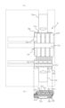
- FIG. FIG. 4 is a schematic explanatory cross-sectional view for explaining a manufacturing process of a capacitor element;
- FIGS. 1 to 4 the configuration of a capacitor element that constitutes a capacitor device according to the present invention will be described.
- FIG. 1 is perspective views (a) to (d) schematically showing an example of the appearance of a capacitor element 10.
- a main body portion 10B having a capacitor function is configured in a bar shape, a shaft-shaped anode terminal portion 11T protrudes in the axial direction from the center of the end portion of the main body portion 10B, and the outer peripheral surface of the main body portion 10B is A cathode terminal portion 14T is formed.
- the body portion 10B has a cylindrical shape
- the anode terminal portion 11T has a cylindrical shape with a diameter smaller than that of the body portion 10B.
- the body portion 10B has a cylindrical shape
- the anode terminal portion 11T' has a prism shape (square prism shape, plate shape) having a smaller cross-sectional area than the body portion 10B.
- the main body portion 10B' is prismatic (square prismatic)
- the anode terminal portion 11T is cylindrical with a smaller cross-sectional area than the main body portion 10B'.
- the main body portion 10B' is prismatic (square prismatic)
- the anode terminal portion 11T' is prismatic (square prismatic, plate-like) smaller than the main body portion 10B.
- All of these capacitor elements 10 are rod-shaped as a whole, and as shown in FIG. 2, have a long (extended) shape in the axial direction.
- the body portion 10B has a capacitor function, and one terminal portion (anode terminal portions 11T and 11T') has a shape protruding from the body portions 10B and 10B' in the axial direction. Also, the terminal portions 11T and 11T' have a smaller cross-sectional shape than the body portions 10B and 10B'.
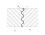
- the capacitor element 10 is configured by coaxially laminating an anode 11, an insulating film 12, an electrolyte part 13, and a cathode 14 from the center in a body part 10B.
- Anode 11 is preferably made of a valve metal such as aluminum, tantalum, chromium, titanium, zinc or niobium.
- the insulating film 12 is preferably composed of an anodized film of these valve metals.
- the surface of the anode 11 is subjected to surface enlarging treatment such as etching to increase the surface area, and the insulating film 12 made of an anodized film formed by chemical conversion treatment is formed on the treated surface.
- an electrolyte part 13 composed of a solid electrolyte, a solid electrolyte and a drive electrolyte, or a solid electrolyte and a functional liquid substance is formed.
- the electrolyte part 13 may exist in layers when it is composed only of a solid electrolyte.
- the electrolyte portion 13 contains a solid electrolyte and a liquid substance, for example, the solid electrolyte portion can be a particulate conductive polymer compound, and the particles aggregate to form a solid electrolyte phase.
- a liquid substance such as a driving electrolyte or a functional liquid substance exists so as to surround the solid electrolyte phase, and can form a liquid substance phase.
- the ESR equivalent series resistance
- the device 1 as a whole can also be characterized by low ESR.
- the cathode 14 provided on the outer periphery of the electrolyte part 13 is not particularly limited, but can be made of, for example, a conductive paste such as carbon paste. Moreover, it is desirable to form a cathode terminal portion 14T made of a conductive paste such as silver paste on the outer peripheral surface of the cathode 14 .
- the cathode terminal portion 14T may be provided integrally with the cathode 14 (or made of the same material) as shown in FIG. 2(b).
- the plurality of anodes 11 are arranged in a parallel posture with a space therebetween in such a manner that the portion to be the anode terminal portion 11T is held by a connecting member 60.
- an etching process surface enlarging treatment
- a chemical conversion process anodic oxidation treatment
- an electrolyte adhesion process an electrolyte adhesion process
- a cathode material conductive paste
- the connecting member 60 is preferably made of a conductive material electrically connected to the anode 11 .
- the electrolyte portion 13, the cathode 14, and the cathode terminal portion 14T can be sequentially formed by immersing in the treatment liquid in the treatment tank. In this way, a plurality of capacitor elements 10 can be manufactured in parallel, and production efficiency can be improved.
- FIG. 5(a) is an enlarged plan view showing a region of the lead frame 50 to be the anode connection lead portion 2 and the cathode connection lead portion 3 of the capacitor device 1
- FIG. 3B is a side view (b) of a portion to be a cathode connection lead portion 3.
- the lead frame 50 is formed of a metal plate that is progressively processed by a press machine or the like, and is formed by punching the metal plate.
- the lead frame 50 has an anode connection region portion 51 protruding like a peninsula into the punched region 50a, and a peninsular shape protruded into the punched region 50a in a direction opposite to the anode connection region 51, and is separated from the anode connection region 51. and a cathode connection region portion 52 configured to face each other across the .
- the anode connection region portion 51 includes a base portion 51a, a head portion 51b provided at the tip of the base portion 51a, and an extension portion 51c extending from the head portion 51b in a direction (lateral side in the drawing) different from the projecting direction. , provided.
- the cathode connection region 52 includes a base portion 52a, a head portion 52b provided at the tip of the base portion 52a, and an extension portion 52c further extending from the head portion 52b in the different direction (side in the drawing).
- a pair of extending portions 51c and 52c extending from left and right side edges of the head portions 51b and 52b are provided.
- the head portion 51b is bent or bent with respect to the base portion 51a so as to have a step 51s in the thickness direction of the lead frame 50.
- the cathode connection region portion 52 is also bent or bent so that the head portion 52b has a step 52s in the thickness direction of the lead frame 50 with respect to the base portion 52a.
- the shape of these steps 51s and 52s can be formed by pressing the lead frame 50. As shown in FIG.
- FIG. 1A and 1B are a plan view (a) and a front view (b) showing an assembly 1A conductively connected to an anode connection lead portion 2 and a cathode connection lead portion 3 which are separated from each other.
- the anode connection lead portion 2 includes an electrode portion 2a formed of at least a portion of the base portion 51a of the anode connection region portion 51, a terminal support portion 2b formed of the head portion 51b, and a terminal holding portion 2c formed of the extension portion 51c.
- the cathode connection lead portion 3 includes an electrode portion 3a formed of at least a part of the base portion 52a of the cathode connection region portion 52, a terminal support portion 3b formed of the head portion 52b, and a terminal holding portion formed of the extension portion 52c. and a portion 3c.
- the plurality of capacitor elements 10 are arranged in parallel with each other in the same (parallel) posture in which the anode terminal portion 11T is arranged on the terminal support portion 2b and the main body portion 10B is arranged on the terminal support portion 3b. aligned to In this first embodiment, a plurality of capacitor elements 10 are arranged in a line on the terminal support portions 2b and 3b.
- the terminal holding portions 2c and 3c protruding from the side edges of the terminal supporting portions 2b and 3b are bent or bent to extend in the parallel direction of the plurality of capacitor elements 10, and the anode terminal portion 11T and the main body portion extend. It is in contact with 10B so as to cover it from above.
- the anode terminal portion 11T is held between the terminal support portion 2b and the terminal holding portion 2c
- the cathode terminal portion 14T is held between the terminal support portion 3b and the terminal holding portion 3c. be. That is, both the anode terminal portion 11T and the cathode terminal portion 14T are supported and held from opposite sides by the terminal supporting portions 2b, 3b and the terminal holding portions 2c, 3c. This reduces the load when the conductive connection portions between the anode terminal portion 11T and the cathode terminal portion 14T and the anode connection lead portion 2 and the cathode connection lead portion 3 receive an external force. Since separation is suppressed, electrical reliability can be improved.
- a pair of terminal holding portions 2c and 3c extend to the left and right sides of the terminal supporting portions 2b and 3b, respectively.
- a part of the plurality of capacitor elements 10 and the rest thereof are shared from the left and right, respectively, and are configured to be held from above.
- the tip portions of the left and right terminal holding portions 2c and 3c may be connected to each other by some member or joining method.
- both the anode terminal portion 11T and the cathode terminal portion 14T are conductively connected to the terminal supporting portions 2b, 3b and the terminal holding portions 2c, 3c at the supporting portions and the holding portions.
- the anode terminal portion 11T is preferably welded to the terminal support portion 2b and the terminal holding portion 2c by laser welding or resistance welding. It is preferable to use a conductive adhesive that can be bonded at a low temperature such as a conductive paste. This is because the life of the capacitor element 10 may be shortened by heating the body portion 10B of the capacitor element 10 when conductively connecting the cathode terminal portion 14T.
- connection resistance of the conductive connection portion can be reduced when the conductive connection mode is welding. Welding also improves the reliability of the conductive connection.
- the form of the conductive connection itself is not particularly limited as long as there is no problem.
- the conductive connections between the terminal supporting portions 2b and 3b and the terminal holding portions 2c and 3c and the anode terminal portion 11T and the cathode terminal portion 14T are the supporting portions of the terminal supporting portions 2b and 3b and the terminal holding portion 2c. , 3c. Therefore, the increase in the number of conductive connection points increases the overall conductive connection area, and the junction resistance of the parallel connection structure of the plurality of capacitor elements 10 can be reduced. Further, by making the surface shape of the holding portions of the terminal holding portions 2c and 3c conform to the surface of the cathode terminal portion 14T, the conductive connection area can be further increased.
- the cathode terminal portions 14T between the adjacent capacitor elements 10 are not in contact with each other (main body portion 10B.), but unlike the illustrated example, by bringing the body portions 10B into contact with each other, the conductive connection area between the plurality of capacitor elements 10 can be increased, and the assembly 1A Compactness can be achieved.
- FIG. 7 shows a cross-sectional view (a) and a vertical cross-sectional view (b) when the capacitor device 1 is formed by molding the assembly 1A with (insulating) resin and enclosing it with the resin material 4.
- FIG. 7 shows a cross-sectional view (a) and a vertical cross-sectional view (b) when the capacitor device 1 is formed by molding the assembly 1A with (insulating) resin and enclosing it with the resin material 4.
- FIG. 7 shows a cross-sectional view (a) and a vertical cross-sectional view (b) when the capacitor device 1 is formed by molding the assembly 1A with (insulating) resin and enclosing it with the resin material 4.
- FIG. 7 shows a cross-sectional view (a) and a vertical cross-sectional view (b) when the capacitor device 1 is formed by molding the assembly 1A with (insulating) resin and enclosing it with the resin material 4.
- FIG. 7 shows a cross-sectional view (a) and a vertical
- the assembly 1A in which a plurality of capacitor elements 10 are held by the terminal supporting portions 2b, 3b and the terminal holding portions 2c, 3c and are conductively connected is covered by the resin material 4. Therefore, the rigidity of the assembly 1A is further improved. For this reason, even if the device is subjected to thermal stress such as solder reflow during mounting on the circuit board or mechanical stress received from the circuit board after mounting, the possibility of defects occurring can be reduced, thereby increasing reliability. improve sexuality.
- the resin material 4 includes the terminal supporting portions 2b and 3b which are arranged inside the electrode portions 2a and 3a with steps 2s and 3s from both upper and lower sides of the drawing, the anode connecting lead portion 2 and the cathode Since the bonding force between the connection lead portion 3 and the resin material 4 can be increased, there is almost no need to change the basic structure of the anode connection lead portion 2 and the cathode connection lead portion 3, and furthermore, without sacrificing compactness, Product reliability can be further enhanced.
- the step amounts of the steps 2s and 3s are set so that the terminal support portions 2b and 3b can support (abut on) the anode terminal portion 11T and the cathode terminal portion 14T.
- the electrode portion 2a of the anode connection lead portion 2 and the electrode portion 3a of the cathode connection lead portion 3 are set at the same height.
- the configuration is basically similar to that of the first embodiment described above, but the terminal holding portions 2c and 3c each extend only from one side of the terminal supporting portions 2b and 3b.
- Each terminal holding portion 2c, 3c is folded back from one side to the other side to hold all the plurality of capacitor elements 10 arranged side by side from above. ing. Even with this configuration, the same effects as in the first embodiment can be obtained.
- the tip portions of the terminal holding portions 2c and 3c are separated from the terminal support portions 2b and 3b, but the tip portions of the terminal holding portions 2c and 3c are folded back from one side to the other side. Later, the other side may be configured to be mechanically and electrically connected to the terminal supporting portions 2b and 3b. Also, in the second embodiment, as long as there is no problem, the configuration can be the same as each point explained in the first embodiment, but the explanation thereof will be omitted.
- a third embodiment of the present invention will be described.
- a plurality of capacitor elements 10 are arranged in two stages on the terminal supporting portions 2b and 3b. That is, some of the plurality of capacitor elements 10 are arranged on the terminal support portions 2b and 3b, but the remaining plurality of capacitor elements 10 are the already arranged part of the plurality of capacitor elements 10. is mounted on an array of a plurality of capacitor elements 10 of Although the plurality of capacitor elements 10 are mounted in two stages in the illustrated example, they may be mounted in three or more stages. Also, the number of capacitor elements 10 arranged in each stage is not particularly limited, and may be the same number as the other stages as shown in the figure, or may be a different number.
- a plurality of terminal holding portions 2c, 3c extend from the terminal supporting portions 2b, 3b, and different terminal holding portions 2c, 3c are connected to the capacitor elements 10 at respective stages of the capacitor elements 10 at a plurality of stages. is configured to hold In the illustrated example, a plurality (two) of terminal holding portions 2c and 3c extend from different locations in the vertical direction of the drawing on the left and right side edges of the terminal supporting portions 2b and 3b. It holds a plurality of capacitor elements 10 respectively.
- the capacitor elements 10 mounted in a plurality of stages can be stably and reliably held in each stage.
- the terminal holding portions 2c and 3c are provided to hold the respective stages of the plurality of capacitor elements 10 mounted in a plurality of stages. It may be held by holding portions 2c and 3c.
- a terminal supporting portion 2d indicated by a dotted line in FIG. 9 supports the anode terminal portion 11T on the second stage (and thereafter).
- This terminal support portion 2d is also preferably conductively connected to the anode terminal portion 11T.
- the capacitor elements 10 in the second stage (or later) are arranged to be shifted in the axial direction with respect to the first stage, and a terminal support portion 3d (not shown) for supporting the cathode terminal portion 14T is provided.
- the terminal holding portion 3c on the first stage often ends up supporting the cathode terminal portion 14T on the second stage (and thereafter) as shown in the illustrated example, only the terminal holding portion 3c is provided. Therefore, the terminal support portion 3d may not be provided.
- the third embodiment can be constructed in the same manner as the points explained in the first or second embodiment as long as there is no problem, but the explanation thereof will be omitted.
- FIG. 10 is a cross-sectional view (a) and a vertical cross-sectional view (b) showing the structure of the capacitor device 1 of this embodiment.
- the conductive connection structure can be maintained by the binding force of the resin material 4.
- FIG. 10 since a plurality of capacitor elements 10 are mounted on the terminal supporting portions 2b and 3b in a plurality of stages, the degree of integration of the capacitor elements 10 can be further increased and the adjacent capacitors
- the resin material 4 is interposed between the elements 10 not only in the planar direction but also in the vertical direction.
- the rigidity of the assembly can be further increased by bonding to the . Therefore, even though a larger number of capacitor elements 10 are connected in parallel, reliability can be easily ensured, and the manufacturing work can be simplified, thereby improving productivity.
- a plurality of capacitor elements 10 stacked in a plurality of stages
- it may be configured to hold a part and the remaining capacitor elements 10 in the same stage, Alternatively, the same plurality of capacitor elements 10 may be held at a plurality of locations by a plurality of terminal holding portions 2c and 3c.
- FIG. 11 shows the structure of an assembly 1A of a plurality of capacitor elements 10, an anode connection lead portion 2 and a cathode connection lead portion 3 in the fourth embodiment.
- This embodiment includes a plurality of capacitor elements 10 mounted in a plurality of stages on the terminal support portions 2b and 3b in the same manner as in the third embodiment. It is different from the third embodiment in that it does not extend from both side edges, but only from one side edge. However, a plurality of terminal holding portions 2c and 3c extending from different positions in the vertical direction of the drawing among the side edges of the terminal supporting portions 2b and 3b correspond to the arrangement of the capacitor elements 10 in a plurality of stages. , is the same as the third embodiment.
- the tip portions of the terminal holding portions 2c and 3c folded back from one side to the other side are separated from the terminal support portions 2b and 3b in the illustrated example, but the tip portions of the terminal holding portions 2c and 3c are separated from each other. After folding from one side to the other side, the other side may be mechanically and electrically connected to the terminal supporting portions 2b and 3b.
- a plurality of terminal holding portions 2c and 3c corresponding to each stage are extended from both side edges of the terminal support portions 2b and 3b, respectively, and are folded back to opposite sides to form capacitor elements 10 in different stages. may be held.
- the fourth embodiment can be constructed in the same manner as the points described in any of the first to third embodiments as long as there is no problem, but the description thereof will be omitted.
- a step 3t is formed in a portion of the cathode connection lead portion 3, in the illustrated example, in a portion adjacent to the terminal support portion 3b. is not embedded in the resin material 4 and is configured to be the electrode portion 3 e exposed from the resin material 4 .
- the capacitor device 1 can be used as a three-terminal capacitor provided with the electrode portion 3e in addition to the electrode portions 2a and 3a.
- the terminal support portions 2b, 3b are displaced inside the resin material 4 with respect to the electrode portions 2a, 3a, 3e due to the presence of the steps 2s, 3s, 3t. Therefore, the bonding area with the resin material 4 can be increased without substantially changing the basic structure of the lead portions 2 and 3 and without sacrificing the compactness of the capacitor device 1. . Therefore, the bonding force between the assembly 1A and the resin material 4 can be increased.
- the fifth embodiment can also be configured in the same manner as the points described in the first to fourth embodiments as long as there is no problem, but the description thereof will be omitted.
- FIG. 13 is an explanatory diagram showing modifications (a) to (c) that can be used in each of the above embodiments.
- Each characteristic configuration of each example of the above-described embodiments can be appropriately replaced with another configuration or arbitrarily combined with each other as long as there is no mutual problem.
- 13(a) to 13(c) can also be appropriately replaced with other configurations or arbitrarily combined with each other as long as they do not interfere with each other. be able to.
- 13A to 13C for convenience of explanation, only one of the terminal supporting portion 2b and the terminal holding portion 2c and the terminal supporting portion 3b and the terminal holding portion 3c is shown, and the other is shown. are omitted.
- the plurality of capacitor elements 10 are provided with an anode terminal portion 11T' having a rectangular cross section or plate shape.
- the terminal supporting portion 2b supports the anode terminal portion 11T'
- the terminal holding portion 2c holds the anode terminal portion 11T'.
- the contact area between the terminal supporting portion 2b and the terminal holding portion 2c can be increased by the anode terminal portion 11T' having a rectangular or plate-like cross section. Since the electrical resistance value of the portion can be further reduced, the reliability can be further improved.
- the plurality of capacitor elements 10 has a main body portion 10B' having a rectangular or prismatic cross section.
- the cathode terminal portion 14T' has a flat portion, it is possible to increase the contact area with the terminal support portion 3b and the terminal holding portion 3c, so that the stability of the assembly is further improved and the bonding is improved. Since the electrical resistance value of the portion can be further reduced, the reliability can be further improved.
- the plurality of capacitor elements include capacitor elements 10 and 10′′ having mutually different dimensions and shapes.
- the element 10 and the capacitor element 10'' having a small outer diameter of the main body portion 10B'' are mixed. In this way, by appropriately combining and assembling the capacitor elements having mutually different dimensions and shapes, high density can be achieved.
- the size of the capacitor element is not particularly limited, but the main body
- the outer diameter of the cross section or the width of one side is preferably within the range of 0.1-10.0 mm, preferably within the range of 0.3-3.0 mm.
- the outer diameter of the main body part 10B is 0.9 mm
- the outer diameter of the body portion 10B'' is 0.5 mm.
- the types of capacitor device 1 can be diversified.
- capacitor elements having mutually different shapes such as a rectangular cross-sectional shape and a rhombic cross-sectional shape may be included.
- the capacitance and rated voltage of the capacitor element may differ from each other.
- a smoothing capacitor When a smoothing capacitor is used in a rectifier circuit, etc., it is necessary to use a capacitor that satisfies a predetermined condition with respect to ripple current, thereby preventing internal heat generation of the used capacitor and avoiding shortening of the life of the capacitor. can be done.
- a combination of a plurality of capacitors may be used in order to reduce the parts cost while satisfying the above conditions.
- the parts cost can be further reduced by making the plurality of capacitors used in combination have mutually different performances. Therefore, as in the example shown in FIG. 13C, by combining capacitor elements having mutually different capacitances and rated voltages, the capacitor device 1 suitable for a specific circuit configuration can be configured while suppressing costs. it becomes possible to
- the terminal supporting portions 2b and 3b and the terminal holding portions 2c and 3c are provided in the anode connecting lead portion 2 or the cathode connecting lead portion 3, so that a plurality of In the assembly (assembly in which a plurality of capacitor elements 10 are connected in parallel) 1A of the capacitor element 10, the anode connection lead portion 2, and the cathode connection lead portion 3, the contact area of the conductive connection portion is increased and the structural stability is improved. Therefore, it is possible to reduce the resistance of the conductive connection portions between the anode terminal portion 11T and the anode connection lead portion 2, and between the cathode terminal portion 14T and the cathode connection lead portion 3, and improve the reliability. can. That is, the resistance of the conductive connection portion of the assembly 1A is lowered and stabilized, and the bonding force between the assembly 1A and the resin material is increased. It is possible to improve the reliability while securing the characteristics of large capacity and low ESR.
- either one of the anode connection lead portion 2 and the cathode connection lead portion 3 may be provided with the terminal support portion and the terminal holding portion.
- both holding portions 2c and 3c are provided.
- only the terminal supporting portion 2b and the terminal holding portion 3c may be provided, or only the terminal supporting portion 3b and the terminal holding portion 2c may be provided.
- one of the anode terminal portion 11T and the cathode terminal portion 14T is supported by the terminal supporting portions 2b and 3b, and the other is held by the terminal holding portions 2c and 3c. Therefore, the assembly 1A can enjoy both the supporting action of the terminal supporting portion and the holding action of the terminal holding portion.
- the terminal holding portions 2c and 3c extend in the parallel direction of the capacitor element 10 from the side edges of the terminal supporting portions 2b and 3b, thereby complicating the structure of the anode connection lead portion 2 or the cathode connection lead portion 3. Since a plurality of capacitor elements 10 can be reliably and easily integrated in the assembly 1A without having to do so, it is possible to further improve reliability and productivity.
- the terminal holding portions 2c and 3c hold the anode terminal portion 11T or the cathode terminal portion 14T from the side opposite to the side supported by the terminal support portions 2b and 3b of the anode terminal portion 11T or the cathode terminal portion 14T. Since the integrity of the assembly 1A in which the capacitor elements 10 are connected in parallel is improved, the reliability is further improved by stabilizing the conductive connection, and the efficiency of the assembly work in the manufacturing process is improved and the conductive connection work is facilitated. productivity can be improved.
- the capacitor element 10 has a body portion 10B in which the anode 11, the insulating film 12 and the cathode 14 are coaxially laminated, and an anode terminal portion 11T projecting in the axial direction from the end of the body portion 10B.
- the plurality of capacitor elements 10 can be arranged in the assembly 1A at high density and the plurality of capacitor elements 10 can be aligned.
- the conductive connection structure can be configured reliably and easily, and the manufacturing of individual capacitor elements 10 can be made more efficient, so that reliability can be ensured and productivity can be improved.
- the anode connection lead portion 2 or the cathode connection lead portion 3 is configured such that the terminal support portions 2b and 3b are shifted inside the resin material 4 with respect to the electrode portions 2a and 3a and arranged inside the resin material 4.
- the terminal support portions for the externally exposed electrode portions 2a, 3a, and 3e can be provided without substantially changing the basic structure and without sacrificing compactness. Since 2b and 3b can be arranged inside the resin material 4, the bonding force between the assembly and the resin material 4 can be further increased due to the increase in the bonding area, so that reliability can be further improved.
- the plurality of capacitor elements 10 are arranged in a manner of being stacked in a plurality of stages on the terminal supporting portions 2b and 3b, more capacitor elements 10 can be compactly integrated, thereby improving reliability. It is possible to achieve both large capacity and compactness while ensuring In particular, by providing a plurality of terminal holding portions 2c and 3c that respectively hold the capacitor elements 10 in different stages, the integration of the assembly 1A can be further enhanced, thereby further improving reliability. be able to.
- the plurality of capacitor elements 10 include capacitor elements 10 having different dimensions or shapes from other capacitor elements 10, various demands can be met while achieving both large capacity and compact size. It is possible to realize the capacitor device 1 having characteristics suitable for the circuit configuration that is used.
- the capacitor device of the present invention is not limited to the illustrated examples described above, and it goes without saying that various modifications can be made without departing from the gist of the present invention.
- the terminal supporting portion and the terminal holding portion are integrated (connected).
- the support portion and the terminal holding portion may be formed separately, or the terminal support portion and the terminal holding portion may be formed of different members (materials) and joined to each other.
- the cathode terminal portions 14T between the adjacent capacitor elements 10 are not in contact with each other (there is a gap between the body portions 10B). shows a modification in which the cathode terminal portions 14T of the adjacent capacitor elements 10 are arranged in parallel or stacked so that the cathode terminal portions 14T are in contact with each other.
- the cathode terminal portions 14T of the capacitor elements 10 arranged adjacent to each other in the vertical direction may be separated from each other by arranging the terminal holding portion 3c therebetween. 3c may be arranged so that they are in contact with each other.
- a solid electrolytic capacitor is used as the capacitor element 10, but in the present invention, an assembly in which a plurality of capacitor elements 10 are connected in parallel is used to achieve a large capacity and a low ESR. Therefore, any capacitor other than a solid electrolytic capacitor can be used as capacitor element 10 .
Landscapes
- Engineering & Computer Science (AREA)
- Power Engineering (AREA)
- Microelectronics & Electronic Packaging (AREA)
- Manufacturing & Machinery (AREA)
- Fixed Capacitors And Capacitor Manufacturing Machines (AREA)
Abstract
La présente invention concerne un dispositif condensateur qui permet d'améliorer la fiabilité tout en conservant l'augmentation de la capacité et les caractéristiques de faible résistance série équivalente (ESR). Un dispositif condensateur 1 selon la présente invention comprend : des parties de support de borne 2b, 3b qui sont chacune disposées sur une partie de conducteur de connexion d'électrode positive 2 ou une partie de conducteur de connexion d'électrode négative 3, et avec lesquelles des parties de borne d'électrode positive 11T ou des parties de borne d'électrode négative 14T d'une pluralité d'éléments de condensateur 10 sont supportées et connectées de manière conductrice ; et des parties de maintien de borne 2c, 3c qui sont chacune disposées sur la partie de conducteur de connexion d'électrode positive 2 ou la partie de conducteur de connexion d'électrode négative 3, et avec lesquelles les parties de borne d'électrode positive 11T ou les parties de borne d'électrode négative 14T de la pluralité d'éléments de condensateur sont maintenues et connectées de manière conductrice.
Applications Claiming Priority (2)
| Application Number | Priority Date | Filing Date | Title |
|---|---|---|---|
| JP2021148833 | 2021-09-13 | ||
| JP2021-148833 | 2021-09-13 |
Publications (1)
| Publication Number | Publication Date |
|---|---|
| WO2023037913A1 true WO2023037913A1 (fr) | 2023-03-16 |
Family
ID=85506637
Family Applications (1)
| Application Number | Title | Priority Date | Filing Date |
|---|---|---|---|
| PCT/JP2022/032311 WO2023037913A1 (fr) | 2021-09-13 | 2022-08-29 | Dispositif condensateur |
Country Status (1)
| Country | Link |
|---|---|
| WO (1) | WO2023037913A1 (fr) |
Citations (7)
| Publication number | Priority date | Publication date | Assignee | Title |
|---|---|---|---|---|
| JPS59143035U (ja) * | 1983-03-14 | 1984-09-25 | 日本電気ホームエレクトロニクス株式会社 | 固体電解コンデンサ |
| JP2004088073A (ja) * | 2002-06-07 | 2004-03-18 | Matsushita Electric Ind Co Ltd | 固体電解コンデンサ |
| WO2006086972A1 (fr) * | 2005-02-18 | 2006-08-24 | Kemet Electronics Corporation | Condensateur ayant une resistance serie equivalente faible, et systeme de condensateur |
| WO2006123451A1 (fr) * | 2005-05-18 | 2006-11-23 | Sanyo Electric Co., Ltd. | Condensateur à électrolyte solide de type superposé et son procédé de fabrication |
| JP2008235410A (ja) * | 2007-03-19 | 2008-10-02 | Matsushita Electric Ind Co Ltd | 固体電解コンデンサ |
| JP2009099877A (ja) * | 2007-10-19 | 2009-05-07 | Sanyo Electric Co Ltd | 固体電解コンデンサ及びその製造方法 |
| JP2011035084A (ja) * | 2009-07-31 | 2011-02-17 | Sanyo Electric Co Ltd | 固体電解コンデンサ |
-
2022
- 2022-08-29 WO PCT/JP2022/032311 patent/WO2023037913A1/fr active Application Filing
Patent Citations (7)
| Publication number | Priority date | Publication date | Assignee | Title |
|---|---|---|---|---|
| JPS59143035U (ja) * | 1983-03-14 | 1984-09-25 | 日本電気ホームエレクトロニクス株式会社 | 固体電解コンデンサ |
| JP2004088073A (ja) * | 2002-06-07 | 2004-03-18 | Matsushita Electric Ind Co Ltd | 固体電解コンデンサ |
| WO2006086972A1 (fr) * | 2005-02-18 | 2006-08-24 | Kemet Electronics Corporation | Condensateur ayant une resistance serie equivalente faible, et systeme de condensateur |
| WO2006123451A1 (fr) * | 2005-05-18 | 2006-11-23 | Sanyo Electric Co., Ltd. | Condensateur à électrolyte solide de type superposé et son procédé de fabrication |
| JP2008235410A (ja) * | 2007-03-19 | 2008-10-02 | Matsushita Electric Ind Co Ltd | 固体電解コンデンサ |
| JP2009099877A (ja) * | 2007-10-19 | 2009-05-07 | Sanyo Electric Co Ltd | 固体電解コンデンサ及びその製造方法 |
| JP2011035084A (ja) * | 2009-07-31 | 2011-02-17 | Sanyo Electric Co Ltd | 固体電解コンデンサ |
Similar Documents
| Publication | Publication Date | Title |
|---|---|---|
| US6680841B2 (en) | Solid electrolytic capacitor and its manufacturing method | |
| JP4492265B2 (ja) | チップ形固体電解コンデンサ | |
| JPH05205984A (ja) | 積層型固体電解コンデンサ | |
| JP4083091B2 (ja) | チップ型固体電解コンデンサ及びその製造方法並びにそれに用いるリードフレーム | |
| JP4653682B2 (ja) | チップ状固体電解コンデンサ | |
| JP4975946B2 (ja) | チップ型固体電解コンデンサ及びその製造方法 | |
| JP4802550B2 (ja) | 固体電解コンデンサ | |
| JP4613699B2 (ja) | 固体電解コンデンサ及びその製造方法とこれを用いたデジタル信号処理基板 | |
| JP5445673B2 (ja) | 固体電解コンデンサ及びその製造方法 | |
| JP5073011B2 (ja) | 固体電解コンデンサ及びその製造方法 | |
| JP2017092237A (ja) | 固体電解コンデンサおよびその製造方法 | |
| JP4895035B2 (ja) | 固体電解コンデンサ | |
| WO2023037913A1 (fr) | Dispositif condensateur | |
| JP4613669B2 (ja) | 固体電解コンデンサ | |
| JP2007043197A (ja) | 積層型コンデンサ | |
| JP2001332446A (ja) | コンデンサ | |
| JP2006032880A (ja) | 固体電解コンデンサ及びその製造方法 | |
| JP5095107B2 (ja) | 固体電解コンデンサ | |
| JP2006100295A (ja) | 固体電解コンデンサ及びその製造方法 | |
| JP2008135425A (ja) | チップ形固体電解コンデンサ | |
| WO2014038203A1 (fr) | Condensateur électrolytique solide | |
| JP5040230B2 (ja) | チップ形固体電解コンデンサ | |
| JP2005228801A (ja) | チップ型固体電解コンデンサ及びそれに用いるリードフレーム | |
| JP2008021774A (ja) | チップ形固体電解コンデンサ及びその製造方法 | |
| JP2005311216A (ja) | 固体電解コンデンサ及びその製造方法 |
Legal Events
| Date | Code | Title | Description |
|---|---|---|---|
| 121 | Ep: the epo has been informed by wipo that ep was designated in this application |
Ref document number: 22867235 Country of ref document: EP Kind code of ref document: A1 |
|
| WWE | Wipo information: entry into national phase |
Ref document number: 2023546888 Country of ref document: JP |
|
| NENP | Non-entry into the national phase |
Ref country code: DE |