WO2023032001A1 - 物品管理システムおよび物品管理方法 - Google Patents
物品管理システムおよび物品管理方法 Download PDFInfo
- Publication number
- WO2023032001A1 WO2023032001A1 PCT/JP2021/031741 JP2021031741W WO2023032001A1 WO 2023032001 A1 WO2023032001 A1 WO 2023032001A1 JP 2021031741 W JP2021031741 W JP 2021031741W WO 2023032001 A1 WO2023032001 A1 WO 2023032001A1
- Authority
- WO
- WIPO (PCT)
- Prior art keywords
- article
- articles
- transport path
- section
- path
- Prior art date
- Legal status (The legal status is an assumption and is not a legal conclusion. Google has not performed a legal analysis and makes no representation as to the accuracy of the status listed.)
- Ceased
Links
Images








Classifications
-
- B—PERFORMING OPERATIONS; TRANSPORTING
- B65—CONVEYING; PACKING; STORING; HANDLING THIN OR FILAMENTARY MATERIAL
- B65G—TRANSPORT OR STORAGE DEVICES, e.g. CONVEYORS FOR LOADING OR TIPPING, SHOP CONVEYOR SYSTEMS OR PNEUMATIC TUBE CONVEYORS
- B65G1/00—Storing articles, individually or in orderly arrangement, in warehouses or magazines
- B65G1/02—Storage devices
- B65G1/04—Storage devices mechanical
- B65G1/137—Storage devices mechanical with arrangements or automatic control means for selecting which articles are to be removed
- B65G1/1373—Storage devices mechanical with arrangements or automatic control means for selecting which articles are to be removed for fulfilling orders in warehouses
- B65G1/1376—Storage devices mechanical with arrangements or automatic control means for selecting which articles are to be removed for fulfilling orders in warehouses the orders being assembled on a commissioning conveyor
-
- G—PHYSICS
- G06—COMPUTING OR CALCULATING; COUNTING
- G06Q—INFORMATION AND COMMUNICATION TECHNOLOGY [ICT] SPECIALLY ADAPTED FOR ADMINISTRATIVE, COMMERCIAL, FINANCIAL, MANAGERIAL OR SUPERVISORY PURPOSES; SYSTEMS OR METHODS SPECIALLY ADAPTED FOR ADMINISTRATIVE, COMMERCIAL, FINANCIAL, MANAGERIAL OR SUPERVISORY PURPOSES, NOT OTHERWISE PROVIDED FOR
- G06Q10/00—Administration; Management
- G06Q10/04—Forecasting or optimisation specially adapted for administrative or management purposes, e.g. linear programming or "cutting stock problem"
- G06Q10/047—Optimisation of routes or paths, e.g. travelling salesman problem
-
- B—PERFORMING OPERATIONS; TRANSPORTING
- B65—CONVEYING; PACKING; STORING; HANDLING THIN OR FILAMENTARY MATERIAL
- B65G—TRANSPORT OR STORAGE DEVICES, e.g. CONVEYORS FOR LOADING OR TIPPING, SHOP CONVEYOR SYSTEMS OR PNEUMATIC TUBE CONVEYORS
- B65G1/00—Storing articles, individually or in orderly arrangement, in warehouses or magazines
- B65G1/02—Storage devices
- B65G1/04—Storage devices mechanical
- B65G1/0478—Storage devices mechanical for matrix-arrangements
-
- B—PERFORMING OPERATIONS; TRANSPORTING
- B65—CONVEYING; PACKING; STORING; HANDLING THIN OR FILAMENTARY MATERIAL
- B65G—TRANSPORT OR STORAGE DEVICES, e.g. CONVEYORS FOR LOADING OR TIPPING, SHOP CONVEYOR SYSTEMS OR PNEUMATIC TUBE CONVEYORS
- B65G1/00—Storing articles, individually or in orderly arrangement, in warehouses or magazines
- B65G1/02—Storage devices
- B65G1/04—Storage devices mechanical
- B65G1/0485—Check-in, check-out devices
-
- B—PERFORMING OPERATIONS; TRANSPORTING
- B65—CONVEYING; PACKING; STORING; HANDLING THIN OR FILAMENTARY MATERIAL
- B65G—TRANSPORT OR STORAGE DEVICES, e.g. CONVEYORS FOR LOADING OR TIPPING, SHOP CONVEYOR SYSTEMS OR PNEUMATIC TUBE CONVEYORS
- B65G1/00—Storing articles, individually or in orderly arrangement, in warehouses or magazines
- B65G1/02—Storage devices
- B65G1/04—Storage devices mechanical
- B65G1/06—Storage devices mechanical with means for presenting articles for removal at predetermined position or level
-
- B—PERFORMING OPERATIONS; TRANSPORTING
- B65—CONVEYING; PACKING; STORING; HANDLING THIN OR FILAMENTARY MATERIAL
- B65G—TRANSPORT OR STORAGE DEVICES, e.g. CONVEYORS FOR LOADING OR TIPPING, SHOP CONVEYOR SYSTEMS OR PNEUMATIC TUBE CONVEYORS
- B65G1/00—Storing articles, individually or in orderly arrangement, in warehouses or magazines
- B65G1/02—Storage devices
- B65G1/04—Storage devices mechanical
- B65G1/137—Storage devices mechanical with arrangements or automatic control means for selecting which articles are to be removed
-
- B—PERFORMING OPERATIONS; TRANSPORTING
- B65—CONVEYING; PACKING; STORING; HANDLING THIN OR FILAMENTARY MATERIAL
- B65G—TRANSPORT OR STORAGE DEVICES, e.g. CONVEYORS FOR LOADING OR TIPPING, SHOP CONVEYOR SYSTEMS OR PNEUMATIC TUBE CONVEYORS
- B65G13/00—Roller-ways
- B65G13/08—Roller-ways of curved form; with branch-offs
- B65G13/10—Switching arrangements
-
- B—PERFORMING OPERATIONS; TRANSPORTING
- B65—CONVEYING; PACKING; STORING; HANDLING THIN OR FILAMENTARY MATERIAL
- B65G—TRANSPORT OR STORAGE DEVICES, e.g. CONVEYORS FOR LOADING OR TIPPING, SHOP CONVEYOR SYSTEMS OR PNEUMATIC TUBE CONVEYORS
- B65G43/00—Control devices, e.g. for safety, warning or fault-correcting
- B65G43/08—Control devices operated by article or material being fed, conveyed or discharged
-
- B—PERFORMING OPERATIONS; TRANSPORTING
- B65—CONVEYING; PACKING; STORING; HANDLING THIN OR FILAMENTARY MATERIAL
- B65G—TRANSPORT OR STORAGE DEVICES, e.g. CONVEYORS FOR LOADING OR TIPPING, SHOP CONVEYOR SYSTEMS OR PNEUMATIC TUBE CONVEYORS
- B65G47/00—Article or material-handling devices associated with conveyors; Methods employing such devices
- B65G47/52—Devices for transferring articles or materials between conveyors i.e. discharging or feeding devices
- B65G47/53—Devices for transferring articles or materials between conveyors i.e. discharging or feeding devices between conveyors which cross one another
- B65G47/54—Devices for transferring articles or materials between conveyors i.e. discharging or feeding devices between conveyors which cross one another at least one of which is a roller-way
-
- G—PHYSICS
- G06—COMPUTING OR CALCULATING; COUNTING
- G06Q—INFORMATION AND COMMUNICATION TECHNOLOGY [ICT] SPECIALLY ADAPTED FOR ADMINISTRATIVE, COMMERCIAL, FINANCIAL, MANAGERIAL OR SUPERVISORY PURPOSES; SYSTEMS OR METHODS SPECIALLY ADAPTED FOR ADMINISTRATIVE, COMMERCIAL, FINANCIAL, MANAGERIAL OR SUPERVISORY PURPOSES, NOT OTHERWISE PROVIDED FOR
- G06Q10/00—Administration; Management
- G06Q10/08—Logistics, e.g. warehousing, loading or distribution; Inventory or stock management
-
- G—PHYSICS
- G06—COMPUTING OR CALCULATING; COUNTING
- G06Q—INFORMATION AND COMMUNICATION TECHNOLOGY [ICT] SPECIALLY ADAPTED FOR ADMINISTRATIVE, COMMERCIAL, FINANCIAL, MANAGERIAL OR SUPERVISORY PURPOSES; SYSTEMS OR METHODS SPECIALLY ADAPTED FOR ADMINISTRATIVE, COMMERCIAL, FINANCIAL, MANAGERIAL OR SUPERVISORY PURPOSES, NOT OTHERWISE PROVIDED FOR
- G06Q10/00—Administration; Management
- G06Q10/08—Logistics, e.g. warehousing, loading or distribution; Inventory or stock management
- G06Q10/087—Inventory or stock management, e.g. order filling, procurement or balancing against orders
-
- Y—GENERAL TAGGING OF NEW TECHNOLOGICAL DEVELOPMENTS; GENERAL TAGGING OF CROSS-SECTIONAL TECHNOLOGIES SPANNING OVER SEVERAL SECTIONS OF THE IPC; TECHNICAL SUBJECTS COVERED BY FORMER USPC CROSS-REFERENCE ART COLLECTIONS [XRACs] AND DIGESTS
- Y02—TECHNOLOGIES OR APPLICATIONS FOR MITIGATION OR ADAPTATION AGAINST CLIMATE CHANGE
- Y02P—CLIMATE CHANGE MITIGATION TECHNOLOGIES IN THE PRODUCTION OR PROCESSING OF GOODS
- Y02P90/00—Enabling technologies with a potential contribution to greenhouse gas [GHG] emissions mitigation
- Y02P90/30—Computing systems specially adapted for manufacturing
Definitions
- the present invention relates to an article management system and an article management method.
- Patent Literature 1 discloses a parcel management system that reduces the labor of a parcel-receiving work for a business operator who is responsible for parcel-receiving work.
- the parcel management system has an automatic acceptance function for automatically accepting parcels and storing them in a warehouse, and an automatic discharge function for automatically discharging parcels to be discharged from the warehouse.
- the present invention has been made in view of the above problems.
- One of the objects of the present invention is to provide a technique for reducing personnel and labor in distribution operations.
- the item management system in the present disclosure is An article management system that performs at least one of delivering articles to customers and accepting articles from customers, a first article transport path that can be used as a first storage location for storing a plurality of articles and that can transfer articles to and from a place for delivering or accepting articles; a second article conveying path that can be used as a second storage location for storing a plurality of articles and that can transfer articles to and from the first article conveying path; a control means for controlling the first article conveying path and the second article conveying path; Prepare.
- the article management method in the present disclosure is a first article transport path that can be used as a first storage location for storing a plurality of articles and that can transfer articles to and from a place for delivering or accepting articles; a second article conveying path that can be used as a second storage location for storing a plurality of articles and that can transfer articles to and from the first article conveying path; includes managing items by computer control.
- This disclosure includes: the computer, A first article transport path that can be used as a first storage place for storing a plurality of articles and that can deliver articles to and from a place for delivering or accepting articles, and storing a plurality of articles.
- a control means for controlling a second article transportation path that can be used as a second storage location and that can transfer articles to and from the first article transportation path; Includes a program to function as
- FIG. 11 is a diagram showing a second configuration example of a second article transport path; It is a block diagram which illustrates the hardware constitutions of a control apparatus.
- 4 is a flow chart illustrating the flow of processing for receiving goods from a customer; It is a figure which shows an example of the information which shows the usage condition of a 2nd goods conveyance path. It is a figure which shows the correspondence of division ID and each division of a 2nd goods conveyance path.
- FIG. 10 is a diagram showing the flow of processing when handing over an article to a customer; It is a figure which shows an example of the information which shows the positional relationship of each division in a 2nd goods conveyance path. It is a figure which shows an example of the information which shows the usage condition of each division in a 2nd goods conveyance path.
- FIG. 5 is a diagram illustrating control operations of a first article conveying path and a second article conveying path, which are executed by a control device;
- FIG. 5 is a diagram illustrating control operations of a first article conveying path and a second article conveying path, which are executed by a control device;
- FIG. 5 is a diagram illustrating control operations of a first article conveying path and a second article conveying path, which are executed by a control device;
- FIG. 5 is a diagram illustrating control operations of a first article conveying path and a second article conveying path, which are executed by a control device; It is a figure showing roughly an example of functional composition of an article management system of a 2nd embodiment.
- FIG. 10 is a diagram showing an arrangement example of a first article transport path, a second article transport path, and a third article transport path in the article management system of the second embodiment; 9 is a flowchart illustrating the flow of processing executed by the control device of the second embodiment;
- each block diagram does not represent a configuration in units of hardware, but a configuration in units of functions, unless otherwise specified. Also, if there are arrows in the figure, the directions of the arrows are merely for making the flow of information easier to understand. The directions of arrows in the drawings do not limit the direction of communication (one-way communication/two-way communication) unless otherwise specified.
- the article management system 1 according to the present disclosure is used, for example, in a distribution center that stores and distributes articles.
- the article management system 1 will be basically described on the assumption that it is used in a distribution center.
- the article management system 1 according to the present disclosure can be used not only in distribution centers but also in fields where article transportation, picking, and the like are performed as business.
- the article management system 1 according to the present disclosure can be similarly used in supermarkets, shopping malls, libraries, rental shops, and the like.
- FIG. 1 is a diagram schematically showing a functional configuration example of an article management system 1 of the first embodiment.
- the article management system 1 includes a control device 10, a first article conveying path 12, and a second article conveying path 14. As shown in FIG. 1,
- the article management system 1 is configured including an automatic article delivery device 20.
- the automatic article delivery device 20 is a device that automatically performs at least one of delivering articles to customers and receiving articles from customers in conjunction with the functional units of the article management system 1 described above.
- the automatic article delivery device 20 can be configured as a device similar to the window device of Patent Document 1 described above, for example.
- the first article conveying path 12 is a device for automatically conveying articles, such as a belt conveyor or roller conveyor.
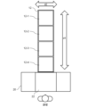
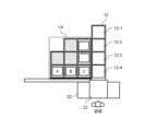
- FIG. 2 is a diagram showing a configuration example of the first article transport path 12.
- the first article transport path 12 extends through an automatic article delivery device 20, more specifically, a customer window 22 of the automatic article delivery device 20 (a place where articles are delivered or received). It is connected to the.
- the first article transport path 12 is configured to have N (N is an integer equal to or greater than 2) sections.
- the term "section" used herein means an area assigned to each article to be conveyed.
- the first article transport path 12 has four sections (12-1, 12-2, 12-3 and 12-4), and a maximum of four articles can be transported at one time.
- each of the sections 12-1 to 12-4 can also be used as storage locations for storing articles (hereinafter also referred to as "first storage locations").
- Each of the sections 12-1 to 12-4 has a mechanism for moving an article in the front-rear direction (extending direction of the conveying path, d1 direction in the drawing), and a mechanism for moving articles in the horizontal direction (extending direction of the conveying path) in each section on the conveying path. a mechanism for moving the article in the orthogonal direction (d2 direction in the figure).
- the control device 10 controls the mechanisms of the sections of the first article transport path 12 to move the articles to be handed over to the customer in front of the automatic article delivery apparatus 20 to the customer window, Articles placed in the customer window of the delivery device 20 can be collected.
- the structure of the first article transport path 12 shown in FIG. 2 is merely an example.
- the structure of the first article transport path 12 can be appropriately determined according to the size of the place where the article management system 1 is introduced.
- the second article conveying path 14, like the first article conveying path 12, is a device for automatically conveying articles, such as a belt conveyor or a roller conveyor.
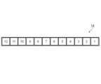
- FIG. 3 is a diagram showing a first configuration example of the second article transport path 14.
- the second article transport path 14 has 12 compartments (indicated by vertical lines) and can carry up to 12 articles at once. These compartments can be used as storage locations for storing articles (hereinafter also referred to as “second storage locations”), similar to the first article transport path 12 .
- the second article transport path 14 also serves as a storage area for temporarily storing articles received from customers.
- Each section of the second article conveying path 14 has at least a mechanism for moving articles in the front-rear direction (extending direction of the conveying path, d1 direction in the figure).
- each section of the conveying path transports articles in the left-right direction (the direction orthogonal to the extending direction of the conveying path, d2 direction in the figure).
- a mechanism for moving may be further provided.
- the articles are moved to each section of the second article transport path 14, for example, as follows.
- the control device 10 controls the mechanisms of the sections of the first article conveying path 12 to move the articles collected from the automatic article delivery device 20 to the furthest point along the extending direction of the first article conveying path 12 .
- the control device 10 changes the moving direction of the article by controlling the mechanism of the section 12-1 to move the article to the section 14-1 of the second article transport path 14.
- the control device 10 controls the mechanism of each section of the second article conveying path 14 to move the articles in such a manner that the articles are packed in order from the leftmost section.
- FIG. 4 is a diagram showing a second configuration example of the second article transport path 14.
- the second article transport path 14 has eight compartments (indicated by vertical lines) and can carry up to eight articles at once. These compartments can be used as storage locations (second storage locations) for storing items, similar to the first article transport path 12 .
- the second article transport path 14 also serves as a storage area for temporarily storing articles to be handed over to customers.
- Each section of the second article conveying path 14 has at least a mechanism for moving articles in the front-rear direction (extending direction of the conveying path, d1 direction in the figure).
- each section of the conveying path transports articles in the left-right direction (the direction orthogonal to the extending direction of the conveying path, d2 direction in the figure).
- a mechanism for moving may be further provided.
- the articles are moved to each section of the second article transport path 14, for example, as follows.
- a person in charge carries an article to be discharged from the automatic article delivery device 20 and places it in one of the sections of the second article transport path 14 that is positioned closest to the front.
- the control device 10 controls the mechanism of each section of the second article conveying path 14 to move the articles from the rightmost section on the line of the sections in which the articles are arranged, in such a way that the articles are packed.
- articles are placed and stored in each section of the second article transport path 14 illustrated in FIG.
- control device 10 controls each mechanism of the first article conveying path 12 and the second article conveying path 14 to input
- the article corresponding to the received information is moved to the customer window 22. ⁇ This allows the customer to receive the desired item.
- the second article conveying path 14 serves as a storage place for temporarily storing articles to be handed over to the customer
- the second article conveying path 14 is provided on the first article conveying path 12.
- An article can be placed in an arbitrary section among a plurality of sections (regions). This configuration is important in the specific process of handing over the goods to the customer, which will be described later in detail.
- the second article transport path 14 has a plurality of lines (conveyors). A plurality of lines in the first article conveying path 12 are connected to different sections of the first article conveying path 12 respectively.
- the number of articles that can be stored in each line is determined based on the position of the compartments of the first article transport path 12 to which the line is connected. For example, in the example of FIG. 4, there are three lines in the d1 direction, and the number of sections provided on each line is 2, 3, and 3 in order from the top. The number of sections provided in each line is determined based on the number of evacuation spaces that can be secured in the first article transport path 12 . For example, the line positioned at the top of the drawing is connected to section 12-2 of first article transport path 12.
- each section of the second article transport path 14 has a mechanism for moving an article in the front-rear direction and a mechanism for moving the article in the left-right direction
- the front-rear direction and the left-right direction in each section can be controlled. By combining them, it becomes possible to move the article to any section on the second article conveying path 14 .
- the control device 10 moves the first article in the manner of a slide puzzle. By controlling the mechanism of each section of the transport path 12 and the second article transport path 14, the article can be moved to any section (position).
- the control device 10 When using the second article conveying path 14 as a route for conveying articles to be handed over to customers, a large amount of space would normally be required to secure a movement route for the articles from each section.
- the control device 10 performs the above-described control, thereby making it possible to create movement paths for articles from each section.
- the structure of the second article transport path 14 shown in FIGS. 3 and 4 is merely an example.
- the structure of the second article transport path 14 can be appropriately determined according to the size of the place where the article management system 1 is introduced.
- the second article transport path 14 may be configured three-dimensionally by arranging planar (two-dimensional) structures as shown in FIGS. 3 and 4 in the height direction.
- the second article transport path 14 further comprises an elevator that enables movement in the height direction in any section.
- Each functional configuration unit of the control device 10 may be implemented by hardware (eg, hardwired electronic circuit, etc.) that implements each functional configuration unit, or may be implemented by a combination of hardware and software (eg, electronic circuit and a program that controls it).
- hardware eg, hardwired electronic circuit, etc.
- software e.g, electronic circuit and a program that controls it.
- FIG. 5 is a block diagram illustrating the hardware configuration of the control device 10. As shown in FIG.
- the control device 10 has a bus 1010 , a processor 1020 , a memory 1030 , a storage device 1040 , an input/output interface 1050 and a network interface 1060 .
- the bus 1010 is a data transmission path for the processor 1020, the memory 1030, the storage device 1040, the input/output interface 1050, and the network interface 1060 to exchange data with each other.
- the method of connecting processors 1020 and the like to each other is not limited to bus connection.
- the processor 1020 is a processor realized by a CPU (Central Processing Unit), a GPU (Graphics Processing Unit), or the like.
- the memory 1030 is a main memory implemented by RAM (Random Access Memory) or the like.
- the storage device 1040 is an auxiliary storage device realized by a HDD (Hard Disk Drive), SSD (Solid State Drive), memory card, ROM (Read Only Memory), or the like.
- Storage device 1040 stores program modules that implement each function of control device 10 described herein. Each function of the control device 10 described in this specification is implemented by the processor 1020 reading the program module into the memory 1030 and executing it.
- the input/output interface 1050 is an interface for connecting the control device 10 and peripheral devices.
- control device 10 can send control signals to first article transport path 12 and second article transport path 14 via input/output interface 1050 .
- the network interface 1060 is an interface for connecting the control device 10 to other devices on the network.
- This network is, for example, a LAN (Local Area Network) or a WAN (Wide Area Network).
- a method for connecting the network interface 1060 to the network may be a wireless connection or a wired connection.
- the control device 10 is communicably connected to the automatic article delivery device 20 via the network interface 1060 .
- the hardware configuration shown in FIG. 5 is merely an example.
- the hardware configuration of the control device 10 according to the present disclosure is not limited to the example of FIG. 5 .
- the control device 10 and the automatic article delivery device 20 are drawn as separate devices, but the automatic article delivery device 20 may also function as the control device 10 .
- the automatic article delivery device 20 for example, the following processing is executed.
- the customer uses an input device (eg, scanner, keyboard, etc.) (not shown) provided in the automatic article delivery device 20 to input information for identifying the article to be placed at the customer window 22 .
- an input device eg, scanner, keyboard, etc.
- a shutter (not shown) provided at the customer window 22 is opened to allow articles to be put in. After the shutter is opened, the customer throws the article into the customer window 22.
- the automatic article delivery device 20 may be configured to measure the size and weight of the thrown-in article at this timing and accept payment of the fee required for delivery of the article.
- the automatic article delivery device 20 may be configured to receive an article delivery option (delivery in a low temperature state, etc.) and execute necessary processing (staff notification processing, etc.).
- an article delivery option delivery in a low temperature state, etc.
- necessary processing staff notification processing, etc.
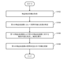
- FIG. 6 is a flowchart illustrating the flow of processing for accepting goods from customers.
- the control device 10 acquires information (item identification information) that identifies the item thrown into the customer window 22 (S102).
- This product identification information is generated based on information input via the input device of the automatic product delivery device 20, for example.
- the control device 10 After obtaining the item identification information, the control device 10 identifies usable (vacant) sections in the second item transport path 14 (S104).
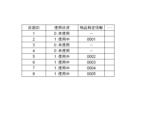
- the second article conveying path 14 can be used by referring to information indicating the usage status of the second article conveying path 14 used for storing articles received from customers, as shown in FIG. Possible partitions can be identified.
- FIG. 7 is a diagram showing an example of information indicating the usage status of the second article transport path 14. As shown in FIG. The information illustrated in FIG. 7 includes information for identifying each partition (partition ID), information indicating whether or not each partition is in use (0: unused, 1: in use), and information for each partition. and item identification information indicating the items stored in the store are associated with each other. Also, it is assumed that the partition IDs shown in FIG.
- FIG. 8 is a diagram showing the correspondence relationship between the section ID and each section of the second article transport path 14. As shown in FIG. 7, the control device 10 can determine that the partitions from "partition ID: 12" to "partition ID: 8" are in use. A compartment can be identified as a compartment for storing items received from customers.
- the control device 10 determines the contents of control to be executed on the first article conveying path 12 and the second article conveying path 14 in order to move the article to the section specified as the section for storing the article, and controls the control.
- the first article conveying path 12 and the second article conveying path 14 are controlled according to the content (S106).
- the control device 10 updates the information illustrated in FIG. 7 (S108). Specifically, in the row corresponding to the section identified in S106, the control device 10 changes the value of the "usage status" column to "1: in use” and changes the value of the "item specifying information" column to S102. Stores the product identification information obtained in .
- the information indicating the usage status of the second article transport path 14 is updated to the latest state.
- the article management system 1 is provided with a mechanism for appropriately collecting the articles stored in the second article transport path 14. It is preferable to have For example, a collection button is provided near the end of the second article transport path 14, and all the articles stored in the second article transport path 14 are retrieved when the button is pressed. A mechanism for moving to a predetermined position may be provided. In this case, the control device 10 controls the second article conveying path 14 in response to receiving the signal generated by pressing the button to remove the articles stored on the second article conveying path 14. move.
- a car or the like is arranged at a predetermined position (for example, a position adjacent to the end of the second article conveying path 14), the articles that have moved on the second article conveying path 14 are placed in the basket. automatically loaded into the car. With such a configuration, an effect of reducing the labor of the person in charge of loading and transporting the articles can be expected.
- the person in charge takes out the goods stored in the second goods transport path 14 and transports them to another place.
- an item received from a customer to be delivered in a cold state may be moved to a warehouse equipped with a refrigeration function in order to store the item in an appropriate temperature zone until the delivery vehicle arrives. Conceivable.
- the section in which the removed article was stored becomes an empty space.
- the control device 10 may be configured to automatically fill in the empty space created by taking out the articles.
- FIG. 9 is a diagram showing the flow of processing when delivering an article to a customer.
- the person in charge places the target item on the second item transport path 14 (storage location for storing the item to be handed over to the customer) as illustrated in FIG.
- the person in charge of operations refers to the advance information such as the desired time of receipt of the goods, and arranges the goods that are expected to be picked up by the customer in the near future in any section of the second goods transport path 14 .
- the control device 10 identifies the section where the article is newly arranged by the person in charge of the business (S202).
- control device 10 can be configured to identify the section where the article is newly placed by using the variation value of the sensing result of the weight sensor provided in each section.
- control device 10 may acquire information indicating the section in which the article is newly arranged via the business terminal used by the person in charge of business.
- control device 10 After identifying the section in which the article is arranged, the control device 10 generates information indicating the positional relationship of each section in the second article conveying path 14 and information indicating the usage status of each section in the second article conveying path 14. is used to determine the control details for the second article transport path 14 (S204).
- FIGS. 10 and 11 An example of information indicating the positional relationship of each section in the second article transportation path 14 and an example of information indicating the usage status of each section in the second article transportation path 14 are shown in FIGS. 10 and 11, respectively. A specific operation example of the control device 10 will be described using these figures.
- the control device 10 identifies the section with the "section ID: 2" as the section ahead of the section with the "section ID: 1" identified in the process of S202. Based on the information shown in FIG. 11, the control device 10 confirms the usage status of the partition with "partition ID: 2". The control device 10 determines that the usage status of the section in front of the section of "section ID: 1" in which the article is newly placed (the section of "section ID: 2") is "1: in use”. Section ID: 2" is determined as "a section in which articles cannot be moved”.
- the controller 10 does not control the second article conveying path 14 because there is no section in front of the section in which the article is newly placed, in which the article can be moved.
- the partition specified in the process of S202 is the partition with "partition ID: 3".
- the control device 10 identifies the section of "section ID: 4" as the section ahead of the section of "section ID: 3" identified in the process of S202. Based on the information shown in FIG. 11, the control device 10 confirms the usage status of "partition ID: 4".
- the control device 10 determines that the use status of the section in front of the section of "section ID: 3" in which the article is newly placed (the section of "section ID: 4") is "0: not used".
- Section ID: 4" is determined to be a section in which articles can be moved.
- the control device 10 further identifies the section ahead of the section judged to be the "section where articles can be moved".
- the control device 10 further identifies the section of "section ID: 5" as the section ahead of the section of "section ID: 4" determined as the "section in which articles can be moved”.
- the control device 10 further confirms the usage status of the partition with "partition ID: 5".
- the control device 10 determines that the section with the section with the section with the ID of 5 is the section where articles cannot be moved. . Based on these determination results, the control device 10 controls the mechanism of the "section ID: 3" section to move the article to the "section ID: 4" section.
- a customer visits the place where the goods management system 1 is installed (for example, a distribution center).
- the customer inputs article specifying information for specifying the target article via an input device (not shown) of the automatic article delivery device 20 .
- the control device 10 identifies the compartment where the article to be moved is stored based on the article identification information input to the automatic article delivery device 20 (S206). Based on the information shown in FIG. 11, for example, the control device 10 can specify the section where the article corresponding to the article specifying information input to the automatic article delivery device 20 is stored. For example, it is assumed that article identification information "0003" is input to the automatic article delivery device 20 . In this case, based on the information shown in FIG. 11, the control device 10 can identify the section with "section ID: 6" as the section where the target article is stored.
- the control device 10 controls the first article conveying path 12 and the second article conveying path 14 based on the storage status of the articles along the route from the specified section to the customer window of the automatic article delivery device 20. (S208). Specifically, the control device 10 temporarily evacuates other items existing on the route from the compartment where the target item is stored to the customer window 22 to an empty space. The first article conveying path 12 and the second article conveying path 14 are operated. This control operation will be described with reference to FIGS. 12 to 15.
- FIG. 12 to 15 are diagrams illustrating control operations of the first article conveying path 12 and the second article conveying path 14 executed by the control device 10. FIG. The examples of FIGS. 12 to 15 show the control contents of the control device 10 that are executed in the case where the partition with "partition ID: 6" is specified in the process of S206.
- the section with "section ID: 6” stores an article A as an article to be moved.
- the article B stored in the section of “section ID: 7" and the article C stored in the section of “section ID: 8" is an obstacle to the movement of the article A.
- the control device 10 controls the first article conveying path 12 and the second article conveying path 14 to move the article B and the article C to the first article conveying path 12. Move to evacuation space.
- the article B stored in the section of "section ID: 7" and the article C stored in the section of “section ID: 8" are located in the section of the first article conveying path 12, respectively. 12-3 and compartment 12-2.
- the control device 10 may move the article B and the article C to the sections 12-2 and 12-1 of the first article transport path 12, respectively.
- the control device 10 further controls the first article conveying path 12 and the second article conveying path 14 to transfer the article A stored in "section ID: 6" to the automatic article delivery device as shown in FIG. 20 to the customer window 22.
- the customer waiting in front of the automatic article delivery device 20 can receive the desired article A.
- the control device 10 opens the first article conveying path 12 and the second article conveying path. 14 is further controlled to return the articles B and C temporarily evacuated to the evacuation space of the first article transport path 12 to their original storage locations. Specifically, as shown in FIG. 15, the control device 10 assigns the articles B and C, which have been temporarily evacuated to the evacuation space of the first article transport path 12, to "Section ID: 7 ” and “partition ID: 8”.
- the desired article is discharged from the automatic article delivery device 20 as described above.
- each section of the second article transport path 14 is provided with a mechanism for moving an article in the front-rear direction and a mechanism for moving an article in the left-right direction.
- the control device 10 will be able to perform the slide puzzle. Items can be moved to the customer window 22 from any compartment in a convenient manner.
- FIG. 16 is a diagram schematically showing a functional configuration example of the article management system 1 of the second embodiment.
- the article management system 1 of this embodiment has a third article conveying path 16 in addition to the first article conveying path 12 and the second article conveying path 14 .
- the control device 10 further includes a management state information acquisition section 110 and an alarm output section 120 .
- the third article conveying path 16 is a device for automatically conveying articles, such as a belt conveyor or a roller conveyor.
- the management state information acquisition unit 110 acquires information (management state information) indicating the state of the article managed in the article management system 1.
- the management status information is information about the status of the goods delivered to the customer or the status of the goods received from the customer.
- the management state information acquisition unit 110 obtains the usage state of the storage location of the first article transportation path 12, the second article transportation path 14, or the storage location of the third article transportation path 16 (eg, the usage rate of the section). , elapsed time since the goods were stored in each compartment), information on the attributes of the goods received from the customer (eg, cold delivery, frozen delivery), etc. are acquired as management status information.
- the alarm output unit 120 determines whether or not the management status of the article indicated by the management status information described above satisfies a predetermined alarm output condition. When the management state of the article indicated by the management state information satisfies a predetermined alarm output condition, the alarm output unit 120 outputs an alarm via an alarm output device. As a result, a person who conducts physical distribution operations at a place where the article management system 1 is installed can notice that some measures should be taken in the article management state.
- FIG. 17 is a diagram showing an arrangement example of the first article conveying path 12, the second article conveying path 14, and the third article conveying path 16 in the article management system 1 of the second embodiment.
- the article management system 1 of this embodiment has both the configuration illustrated in FIG. 3 and the configuration illustrated in FIG.
- the second article conveying path 14 in the present embodiment is configured so that articles can be transferred to and from the first article conveying path 12 in the same manner as the article conveying path exemplified in FIG. , is used as a storage place for goods to be handed over to customers.
- the third article conveying path 16 of the present embodiment is configured to be able to deliver articles to and from the first article conveying path 12 in the same manner as the article conveying path exemplified in FIG. It is used as a storage place to store goods received from customers.
- Each section of the third article conveying path 16 has at least a mechanism for moving articles in the front-rear direction (extending direction of the conveying path).
- Each section of the third article conveying path 16, like the first article conveying path 12, is arranged in each section on the conveying path in the left-right direction (the direction orthogonal to the extending direction of the conveying path). ) may further include a mechanism for moving the article.
- a car 30 (collection place for goods) for collecting goods received from customers using the automatic goods delivery device 20, and a distribution center for storing the collected goods.
- a warehouse 40 is included.
- the car 30 and the distribution warehouse 40 are the first article transport path when viewed from the place where the customer window 22 is provided (the place where the goods are delivered to the customer or the place where the goods are received from the customer). 12, located on the opposite side via the second article conveying path 14 and the third article conveying path 16. As shown in FIG.
- the third article conveying path 16 for conveying the articles received from the automatic article delivery device 20 is provided as the third article conveying path for conveying the articles to be handed over to the customer. It is preferable to arrange it at a position closer to the car 30 and the distribution warehouse 40 than the article transport path 14 of No. 2.
- monitor 122 and the indicator lamp 124 are provided at positions that can be visually recognized from the space where the person in charge of the work is working.
- Alarm output unit 120 controls monitor 122 and indicator lamp 124 to output an alarm when a predetermined alarm output condition is satisfied.
- the alarm output unit 120 can output a message to the monitor 122 according to the alarm output conditions that have been met.
- "a predetermined number or more of articles are stored in the storage location of the third article transport path 16" is set as one of the alarm output conditions, and the alarm output unit 120 acquires Assume that it is determined that the alarm output condition is satisfied based on the received management state information.
- the alarm output unit 120 outputs, for example, a message such as "The storage location of the third article transportation path 16 is running out of space" or "The storage location of the third article transportation path 16 is full.” Print a message.
- the alarm output unit 120 obtains Assume that it is determined that the alarm output condition is satisfied based on the management state information. In this case, the alarm output unit 120 outputs a message such as "There is an article left in the storage area of the second article transport path 14." As another example, “received refrigerated or frozen delivery” is set as an alarm output condition, and the alarm output unit 120 determines whether the alarm output condition is satisfied based on the acquired management state information. Suppose that it is determined that In this case, the alarm output unit 120 outputs, for example, a message such as "Goods for refrigerated delivery/frozen delivery have been received.”
- the alarm output unit 120 may control the lighting state of the indicator lamp 124 to output an alarm. For example, when the indicator lamp 124 corresponding to each storage location of an article is provided, the alarm output unit 120 performs control such as lighting the indicator lamp 124 corresponding to the storage location to be alarmed based on the management state information. It can be carried out. Further, the alarm output unit 120 may be configured to output an alarm via a terminal owned by each person in charge of business (for example, a smart phone or a tablet terminal for business use).
- FIG. 18 is a flowchart illustrating the flow of processing executed by the control device 10 of the second embodiment.
- the management status information acquisition unit 110 monitors the status of the articles managed by the article management system 1 (S302). For example, the management state information acquisition unit 110 monitors whether or not new articles have been received from customers, or whether or not the business personnel has newly placed articles to be handed over to customers on the second article transport path 14. .
- the management state information acquisition unit 110 updates the article management information based on the monitoring result of the state of the article (S304). For example, when receiving a new item from a customer, the management state information acquisition unit 110 stores the item in question (eg, the section on the second item transport path 14 where the item is stored), the item Information such as the time when the item was received and the attribute of the item (e.g. refrigerated delivery item/frozen delivery item) are acquired. Then, management state information acquisition section 110 adds the acquired information about the item to the item management information stored in a predetermined storage area (memory 1030, storage device 1040, etc.).
- the alarm output unit 120 refers to the article management information stored in the predetermined storage area, and determines whether the management state of the article indicated by the article management information satisfies the predetermined alarm condition. is determined (S306). If the item management status indicated by the item management information satisfies a predetermined alarm condition (S306: YES), the alarm output unit 120 outputs an alarm via an alarm output device. The alarm output unit 120 outputs messages such as those exemplified above to the monitor 122 and controls the lighting state of the indicator lamp 124 . If the item management status indicated by the item management information does not satisfy the predetermined alarm condition (S306: NO), the alarm output unit 120 does not output an alarm.
- the alarm from the alarm output unit 120 enables the person in charge of operations to notice that the condition of the managed article should be confirmed and improved, and to take appropriate measures.
- An article management system that performs at least one of delivering articles to customers and accepting articles from customers, a first article transport path that can be used as a first storage location for storing a plurality of articles and that can transfer articles to and from a place for delivering or accepting articles; a second article conveying path that can be used as a second storage location for storing a plurality of articles and that can transfer articles to and from the first article conveying path; a control means for controlling the first article conveying path and the second article conveying path;
- a goods management system comprising: 2.
- the second article transport path includes a hoistway, and the second storage area is three-dimensionally configured. 1.
- the second article transport path stores articles to be handed over to the customer. 1. or 2.
- the first article transport path has N (N is an integer equal to or greater than 2) areas as the first storage locations,
- the second article transport path is configured so that an article can be placed in any one of the N areas, 3.
- the second article transport path is composed of a plurality of conveyors, the number of articles that each of the plurality of conveyors can store is determined based on the position of the area of the first article transport path to which each conveyor is connected; 4.
- the article management system described in . 6. used in distribution centers, 1. to 5.
- the article management system according to any one of. 7.
- a third article transport path that can be used as a third storage location for storing a plurality of articles and that can transfer articles to and from the first article transport path;
- the second article transport path stores articles to be handed over to customers,
- the third article transport path stores articles received from customers, 1. to 6.
- the article management system according to any one of. 8.
- a physical distribution warehouse or collection place is located on the opposite side of the location where the goods are delivered or accepted via the first goods transport path, the second goods transport path, and the third goods transport path. is provided,
- the third article transportation path is located closer to the distribution warehouse or the collection location than the second article transportation path, 7.
- a management state information acquiring means for acquiring management state information indicating a management state of an article to be handed over to a customer or an article received from a customer; alarm output means for outputting an alarm when the management status of the article indicated by the management status information satisfies a predetermined alarm output condition; 7. or 8.
- the article management system described in . 10 a first article transport path that can be used as a first storage location for storing a plurality of articles and that can transfer articles to and from a place for delivering or accepting articles; a second article conveying path that can be used as a second storage location for storing a plurality of articles and that can transfer articles to and from the first article conveying path; is managed by a computer. 11.
- the second article transport path includes a hoistway, and the second storage area is three-dimensionally configured. 10.
- the second article transport path stores articles to be handed over to the customer. 10. or 11.
- the first article transport path has N (N is an integer equal to or greater than 2) areas as the first storage locations,
- the second article transport path is configured so that an article can be placed in any one of the N areas, 12.
- the second article transport path is composed of a plurality of conveyors, the number of articles that each of the plurality of conveyors can store is determined based on the position of the area of the first article transport path to which each conveyor is connected; 13.
- the article management method according to any one of . 16. further comprising a third article transport path that can be used as a third storage location for storing a plurality of articles and that can transfer articles to and from the first article transport path;
- the second article transport path stores articles to be handed over to customers,
- the third article transport path stores articles received from customers, 10. to 15.
- the article management method according to any one of . 17.
- a physical distribution warehouse or collection place is located on the opposite side of the location where the goods are delivered or accepted via the first goods transport path, the second goods transport path, and the third goods transport path. is provided,
- the third article transportation path is located closer to the distribution warehouse or the collection location than the second article transportation path, 16.
- the computer Acquire management status information indicating the management status of goods to be handed over to customers or goods received from customers, outputting an alarm when the management status of the article indicated by the management status information satisfies a predetermined alarm output condition; 16. including or 17.
- the article management method described in . 19. the computer A first article transport path that can be used as a first storage place for storing a plurality of articles and that can deliver articles to and from a place for delivering or accepting articles, and storing a plurality of articles. a control means for controlling a second article transportation path that can be used as a second storage location and that can transfer articles to and from the first article transportation path; A program to function as 20.
- the second article transport path includes a hoistway, and the second storage area is three-dimensionally configured.
- the second article transport path stores articles to be handed over to the customer. 19. or 20. program described in . 22.
- the first article transport path has N (N is an integer equal to or greater than 2) areas as the first storage locations,
- the second article transport path is configured so that an article can be placed in any one of the N areas, 21. program described in . 23.
- the second article transport path is composed of a plurality of conveyors, the number of articles that each of the plurality of conveyors can store is determined based on the position of the area of the first article transport path to which each conveyor is connected; 22. program described in . 24. used in distribution centers, 19. to 23.
- a third article transport path that can be used as a third storage location for storing a plurality of articles and that can transfer articles to and from the first article transport path;
- the second article transport path stores articles to be handed over to customers,
- the third article transport path stores articles received from customers, 19. to 24.
- a physical distribution warehouse or collection place is located on the opposite side of the location where the goods are delivered or accepted via the first goods transport path, the second goods transport path, and the third goods transport path. is provided,
- the third article transportation path is located closer to the distribution warehouse or the collection location than the second article transportation path, 25. program described in . 27.
- management status information acquisition means for acquiring management status information indicating the management status of goods to be handed over to customers or goods received from customers; further functions as alarm output means for outputting an alarm when the management status of the article indicated by the management status information satisfies a predetermined alarm output condition; 25. or 26. program described in .
- control device 1010 bus 1020 processor 1030 memory 1040 storage device 1050 input/output interface 1060 network interface 110 management state information acquisition unit 120 alarm output unit 122 monitor 124 indicator light 12 first article transport path 14 second article Transport path 16 Third article transport path 20 Automatic article delivery device 22 Customer window 30 Basket 40 Distribution warehouse
Landscapes
- Engineering & Computer Science (AREA)
- Business, Economics & Management (AREA)
- Economics (AREA)
- Human Resources & Organizations (AREA)
- Mechanical Engineering (AREA)
- Strategic Management (AREA)
- Physics & Mathematics (AREA)
- Entrepreneurship & Innovation (AREA)
- Operations Research (AREA)
- Quality & Reliability (AREA)
- Marketing (AREA)
- Tourism & Hospitality (AREA)
- Development Economics (AREA)
- General Business, Economics & Management (AREA)
- General Physics & Mathematics (AREA)
- Theoretical Computer Science (AREA)
- Game Theory and Decision Science (AREA)
- Mathematical Physics (AREA)
- Accounting & Taxation (AREA)
- Finance (AREA)
Priority Applications (3)
| Application Number | Priority Date | Filing Date | Title |
|---|---|---|---|
| PCT/JP2021/031741 WO2023032001A1 (ja) | 2021-08-30 | 2021-08-30 | 物品管理システムおよび物品管理方法 |
| US18/684,961 US20240367901A1 (en) | 2021-08-30 | 2021-08-30 | Article management system, article management method and non-transitory computer-readable medium |
| JP2023544809A JPWO2023032001A1 (enExample) | 2021-08-30 | 2021-08-30 |
Applications Claiming Priority (1)
| Application Number | Priority Date | Filing Date | Title |
|---|---|---|---|
| PCT/JP2021/031741 WO2023032001A1 (ja) | 2021-08-30 | 2021-08-30 | 物品管理システムおよび物品管理方法 |
Publications (1)
| Publication Number | Publication Date |
|---|---|
| WO2023032001A1 true WO2023032001A1 (ja) | 2023-03-09 |
Family
ID=85412333
Family Applications (1)
| Application Number | Title | Priority Date | Filing Date |
|---|---|---|---|
| PCT/JP2021/031741 Ceased WO2023032001A1 (ja) | 2021-08-30 | 2021-08-30 | 物品管理システムおよび物品管理方法 |
Country Status (3)
| Country | Link |
|---|---|
| US (1) | US20240367901A1 (enExample) |
| JP (1) | JPWO2023032001A1 (enExample) |
| WO (1) | WO2023032001A1 (enExample) |
Families Citing this family (1)
| Publication number | Priority date | Publication date | Assignee | Title |
|---|---|---|---|---|
| EP4443351A4 (en) * | 2021-12-01 | 2025-02-26 | Fujitsu Limited | Information processing device, planning method, and planning program |
Citations (6)
| Publication number | Priority date | Publication date | Assignee | Title |
|---|---|---|---|---|
| JPH09202412A (ja) * | 1996-01-26 | 1997-08-05 | Mazda Motor Corp | 多種混流物品の搬送出荷システム |
| JP2004075365A (ja) * | 2002-08-22 | 2004-03-11 | Ito Denki Kk | 立体倉庫装置及び立体倉庫の収納物品搬送方法 |
| JP2015040121A (ja) * | 2013-08-23 | 2015-03-02 | 株式会社ダイフク | 自動ピッキング設備 |
| JP2015098397A (ja) * | 2013-11-20 | 2015-05-28 | 株式会社ダイフク | 物品搬送設備 |
| US20190002202A1 (en) * | 2015-12-22 | 2019-01-03 | Savoye | System of buffer storage and sequencing of loads upstream to at least one preparing station. |
| WO2020246543A1 (ja) * | 2019-06-05 | 2020-12-10 | 日本電気株式会社 | 荷物管理システム、荷物管理方法、プログラムを記憶する記憶媒体 |
-
2021
- 2021-08-30 WO PCT/JP2021/031741 patent/WO2023032001A1/ja not_active Ceased
- 2021-08-30 JP JP2023544809A patent/JPWO2023032001A1/ja active Pending
- 2021-08-30 US US18/684,961 patent/US20240367901A1/en active Pending
Patent Citations (6)
| Publication number | Priority date | Publication date | Assignee | Title |
|---|---|---|---|---|
| JPH09202412A (ja) * | 1996-01-26 | 1997-08-05 | Mazda Motor Corp | 多種混流物品の搬送出荷システム |
| JP2004075365A (ja) * | 2002-08-22 | 2004-03-11 | Ito Denki Kk | 立体倉庫装置及び立体倉庫の収納物品搬送方法 |
| JP2015040121A (ja) * | 2013-08-23 | 2015-03-02 | 株式会社ダイフク | 自動ピッキング設備 |
| JP2015098397A (ja) * | 2013-11-20 | 2015-05-28 | 株式会社ダイフク | 物品搬送設備 |
| US20190002202A1 (en) * | 2015-12-22 | 2019-01-03 | Savoye | System of buffer storage and sequencing of loads upstream to at least one preparing station. |
| WO2020246543A1 (ja) * | 2019-06-05 | 2020-12-10 | 日本電気株式会社 | 荷物管理システム、荷物管理方法、プログラムを記憶する記憶媒体 |
Also Published As
| Publication number | Publication date |
|---|---|
| JPWO2023032001A1 (enExample) | 2023-03-09 |
| US20240367901A1 (en) | 2024-11-07 |
Similar Documents
| Publication | Publication Date | Title |
|---|---|---|
| US12354060B2 (en) | Systems and methods of storing and retrieving retail store product inventory | |
| JP7212910B2 (ja) | 物品管理システム、物流システム、サーバ機器、及び物品管理方法 | |
| JP6510436B2 (ja) | 物品搬送システム、搬送装置及び物品搬送方法 | |
| JP6763809B2 (ja) | 経路決定装置、経路決定方法及び経路決定プログラム | |
| JP5811040B2 (ja) | 物品仕分け設備の運用方法及び物品仕分け設備 | |
| CN107902316A (zh) | 面料卷智能仓储系统及控制方法 | |
| CN104903921A (zh) | 补充零售设施 | |
| JP2020521694A (ja) | 完全自動セルフサービス店舗 | |
| KR102797823B1 (ko) | 재고 품목을 주문처리하기 위한 방법 및 시스템 | |
| JP7454746B2 (ja) | 搬送システム及び方法 | |
| JP2020203777A (ja) | 荷物取出装置 | |
| CN107067196A (zh) | 一种基于物联网配送柜的配送系统和配送方法 | |
| JP2018188235A (ja) | ピッキングシステム | |
| JP4040580B2 (ja) | 運行管理サーバおよび運行管理プログラム | |
| JP2009263018A (ja) | ピッキングシステム | |
| JP5417034B2 (ja) | ピッキングシステム | |
| KR20230041080A (ko) | 정보 처리 장치, 정보 처리 방법 및 프로그램 | |
| KR20150142702A (ko) | 오프라인 쇼핑 시스템, 오프라인 쇼핑 시스템에 이용되는 물품이송장치, 및 오프라인 쇼핑 방법 | |
| US20240367901A1 (en) | Article management system, article management method and non-transitory computer-readable medium | |
| JP2004231370A (ja) | ピッキング設備 | |
| TW202011300A (zh) | 存取物流物件並販售商品的裝置和方法以及儲存媒體 | |
| JP2000272716A (ja) | 物品保管管理システム | |
| JPH11263407A (ja) | ピッキングシステム | |
| JPWO2023032001A5 (enExample) | ||
| JP2021147149A (ja) | 保冷物品の配送方法及び配送システム |
Legal Events
| Date | Code | Title | Description |
|---|---|---|---|
| 121 | Ep: the epo has been informed by wipo that ep was designated in this application |
Ref document number: 21955898 Country of ref document: EP Kind code of ref document: A1 |
|
| WWE | Wipo information: entry into national phase |
Ref document number: 2023544809 Country of ref document: JP |
|
| NENP | Non-entry into the national phase |
Ref country code: DE |
|
| 122 | Ep: pct application non-entry in european phase |
Ref document number: 21955898 Country of ref document: EP Kind code of ref document: A1 |