WO2023021679A1 - 光通信装置、光通信装置の制御方法 - Google Patents
光通信装置、光通信装置の制御方法 Download PDFInfo
- Publication number
- WO2023021679A1 WO2023021679A1 PCT/JP2021/030520 JP2021030520W WO2023021679A1 WO 2023021679 A1 WO2023021679 A1 WO 2023021679A1 JP 2021030520 W JP2021030520 W JP 2021030520W WO 2023021679 A1 WO2023021679 A1 WO 2023021679A1
- Authority
- WO
- WIPO (PCT)
- Prior art keywords
- optical signal
- signal processing
- processing unit
- optical
- abnormality
- Prior art date
- Legal status (The legal status is an assumption and is not a legal conclusion. Google has not performed a legal analysis and makes no representation as to the accuracy of the status listed.)
- Ceased
Links
Images




Classifications
-
- H—ELECTRICITY
- H04—ELECTRIC COMMUNICATION TECHNIQUE
- H04B—TRANSMISSION
- H04B10/00—Transmission systems employing electromagnetic waves other than radio-waves, e.g. infrared, visible or ultraviolet light, or employing corpuscular radiation, e.g. quantum communication
- H04B10/07—Arrangements for monitoring or testing transmission systems; Arrangements for fault measurement of transmission systems
- H04B10/075—Arrangements for monitoring or testing transmission systems; Arrangements for fault measurement of transmission systems using an in-service signal
- H04B10/079—Arrangements for monitoring or testing transmission systems; Arrangements for fault measurement of transmission systems using an in-service signal using measurements of the data signal
Definitions
- the present invention relates to an optical communication device and the like capable of setting a mask according to the combination of optical signal processing units inside the optical communication device.
- Alarm masking is used to limit the alarms issued and mask unnecessary alarms when a failure occurs in a communication device.
- Patent Literatures 1 and 2 disclose techniques related to alarm masks. Further, in general communication devices, alarm mask settings are fixedly written in the firmware of each communication device.
- an optical communication device that transmits and receives optical signals is generally configured by combining optical signal processing units that process optical signals.
- Such an optical communication device has different functions according to the combination of internal optical signal processing units, and mask settings required on the system also differ according to the functions. Therefore, if the mask settings are written in the firmware, the mask settings corresponding to various functions realized by the optical communication device cannot be set appropriately.
- the present invention has been made in view of the above problems, and an object of the present invention is to provide an optical communication device or the like that can set a mask according to a combination of optical signal processing units inside the optical communication device. It is to be.
- the optical communication device of the present invention is a plurality of optical signals, comprising: processing means for processing input optical signals; output means for outputting the optical signals processed by the processing means; and detection means for detecting an abnormality in the optical signals in the output means a processing unit; receiving means for receiving the notification of the abnormality from the detecting means in the plurality of optical signal processing units and outputting the notification to the outside; with The plurality of optical signal processing units are provided on one optical path, The receiving means is from the specific optical signal processing unit having the detection means that has detected the abnormality among the plurality of optical signal processing units, to the next stage connected to the subsequent stage on the optical path of the specific optical signal processing unit Based on the mask setting set for the optical signal processing unit, the abnormality notification from the detection means provided in the optical signal processing unit with the mask setting is not output to the outside, and the mask setting is performed. The notification of the abnormality from the detection means provided in the optical signal processing unit in which the optical signal processing unit is not operated is output to the outside.
- a control method for an optical communication device includes: a plurality of optical signals, comprising: processing means for processing input optical signals; output means for outputting the optical signals processed by the processing means; and detection means for detecting an abnormality in the optical signals in the output means a processing unit; receiving means for receiving the notification of the abnormality from the detecting means in the plurality of optical signal processing units and outputting the notification to the outside;
- a control method for an optical communication device comprising The plurality of optical signal processing units are provided on one optical path, The receiving means is from the specific optical signal processing unit having the detection means that has detected the abnormality among the plurality of optical signal processing units, to the next stage connected to the subsequent stage on the optical path of the specific optical signal processing unit Based on the mask setting set for the optical signal processing unit, the abnormality notification from the detection means provided in the optical signal processing unit with the mask setting is not output to the outside, and the mask setting is performed. outputting to the outside a notification of an abnormality from the detection means provided in the optical signal processing unit where the optical signal processing unit is
- an optical communication device or the like capable of setting a mask according to the combination of optical signal processing units inside the optical communication device.
- FIG. 4 is a flow chart showing the operation of the optical communication device according to the first embodiment of the present invention
- 1 is a block diagram showing a configuration example of an optical communication device according to a first embodiment of the present invention
- FIG. 4 is a block diagram showing a modification of the optical communication device according to the first embodiment of the present invention
- FIG. 5 is a block diagram showing a configuration example of an optical communication device according to a second embodiment of the present invention
- 8 is a flow chart showing the operation of the optical communication device according to the second embodiment of the present invention
- FIG. 1 is a schematic diagram showing a configuration example of an optical communication device 1.
- the optical communication device 1 includes a first optical signal processing section 10, a second optical signal processing section 20, a third optical signal processing section 30, and reception means .
- the optical communication device 1 receives an optical signal input from the upper side in FIG. 1 and outputs an optical signal from the lower side in FIG.
- the optical communication device 1 is an optical communication device that processes input optical signals using a first optical signal processing section 10 , a second optical signal processing section 20 and a third optical signal processing section 30 .
- the processing is, for example, amplification of an optical signal.
- the first optical signal processing unit 10 includes first processing means 11 , first output means 12 and first detection means 13 .
- the first optical signal processing section 10 is connected to the second optical signal processing section 20 .
- the first optical signal processing unit 10 receives an optical signal input from the upper side in FIG. 1 and outputs the optical signal to the second optical signal processing unit 20 .
- the first processing means 11 processes the optical signal.
- the first processing means 11 is, for example, an optical amplifier.
- the first output means 12 outputs the optical signal processed by the first processing means 11 .
- the first output means 12 is, for example, an optical output port.
- the first detection means 13 detects an abnormality in the optical signal in the first output means 12 .
- the first detection means 13 detects an anomaly in the optical signal when the intensity of the optical signal is below the threshold.
- the first processing means 11 is an optical amplifier that amplifies an optical signal in accordance with pumping light
- the first detecting means 13 detects an abnormality in the optical signal when the intensity of the pumping light is equal to or less than a threshold.
- an optical amplifier is an EDFA (Erbium Doped Fiber Amplifier).
- the first detection means 13 notifies the reception means 40 of the abnormality in the optical signal.
- the second optical signal processing unit 20 includes a second processing means 21 , a second output means 22 and a second detection means 23 .
- the second optical signal processing section 20 is connected to the first optical signal processing section 10 and the third optical signal processing section 30 .
- the second optical signal processing section 20 receives an optical signal input from the first optical signal processing section 10 and outputs the optical signal to the third optical signal processing section 30 .
- the second processing means 21 processes the optical signal.
- the second processing means 21 is, for example, an optical amplifier.
- the second output means 22 outputs the optical signal processed by the second processing means 21 .
- the second output means 22 is, for example, an optical output port.
- the second detection means 23 detects an abnormality in the optical signal in the second output means 22 .
- the second detection means 23 detects an anomaly in the optical signal when the intensity of the optical signal is below the threshold.
- the second processing means 21 is an optical amplifier that amplifies the optical signal according to the excitation light
- the second detection means 23 detects an abnormality in the optical signal when the intensity of the excitation light is equal to or less than the threshold.
- an optical amplifier is an EDFA.
- the third optical signal processing unit 30 includes a third processing means 31 , a third output means 32 and a third detection means 33 .
- the third optical signal processing section 30 is connected to the second optical signal processing section 20 .
- the third optical signal processing unit 30 receives an optical signal input from the second optical signal processing unit 20 and outputs the optical signal to the outside of the optical communication device 1 (lower side in FIG. 1).
- the third processing means 31 processes the optical signal.
- the third processing means 31 is, for example, an optical amplifier.
- a third output means 32 outputs the optical signal processed by the third processing means 31 .
- the third output means 32 is, for example, an optical output port.
- a third detection means 33 detects an abnormality in the optical signal in the second output means 22 .
- the third detection means 33 detects an anomaly in the optical signal when the intensity of the optical signal is below the threshold.
- the third processing means 31 is an optical amplifier that amplifies an optical signal according to pumping light
- the third detecting means 33 detects an abnormality in the optical signal when the intensity of the pumping light is equal to or less than a threshold.
- an optical amplifier is an EDFA.
- the reception means 40 receives the first detection means 13, the second Abnormal notifications from the detection means 23 and the third detection means 33 are accepted.
- the reception unit 40 receives from a specific optical signal processing unit among the plurality of optical signal processing units 10, 20, and 30 an optical signal processing of the next stage connected to a subsequent stage on the optical path of the specific optical signal processing unit.
- the mask setting for the optical signal processing unit 30 of No. 3 is stored. These mask settings are input to the reception unit 40 by the user of the optical communication device 1 or the like.
- the reception means 40 validates the mask setting set by the optical signal processing unit including the detection means that has notified the abnormality among the plurality of detection means 13, 23, and 33. Specifically, when notified of an abnormality by the first detection means 13 , the reception means 40 validates the mask setting from the first optical signal processing section 10 to the second optical signal processing section 20 . Further, when notified of an abnormality from the second detection means 23 , the reception means 40 validates the mask setting from the second optical signal processing section 20 to the third optical signal processing section 30 .
- the reception unit 40 does not output to the outside the notification of abnormality from the detection unit provided in the optical signal processing unit with effective mask setting, and is provided in the optical signal processing unit without effective mask setting.
- the notification of abnormality from the detected means is output to the outside.
- the reception unit 40 when an abnormality is notified from all of the plurality of detection means 13, 23, and 33, the mask settings for the second optical signal processing section 20 and the third optical signal processing section 30 are effective. Therefore, the reception unit 40 in this case outputs to the outside the notification of abnormality from the first detection unit 13 provided in the first optical signal processing unit 10 in which the effective mask setting is not performed. On the other hand, the reception unit 40 receives the second detection unit 23 and the third detection unit 33 provided in the second optical signal processing unit 20 and the third optical signal processing unit 30 with valid mask settings. Do not output the abnormal notification from the external.
- the reception unit 40 in this case outputs to the outside the notification of abnormality from the second detection unit 23 provided in the second optical signal processing unit 20 in which the effective mask setting is not performed.
- the accepting means 40 does not output to the outside the notification of the abnormality from the third detecting means 33 provided in the third optical signal processing section 30 for which the effective mask setting has been made.
- the receiving means 40 indicates to the outside of the optical communication device 1 that an abnormality has occurred in each optical signal processing unit by calling from the speaker, displaying on the display, or notifying another communication device.
- FIG. 2 is a flow chart showing an operation example of the optical communication device 1 .
- the accepting unit 40 stores mask settings set from a specific optical signal processing unit to a next-stage optical signal processing unit connected to a subsequent stage on the optical path of the specific optical signal processing unit (S101). . Specifically, in the optical communication device 1 shown in FIG. 20 to the third optical signal processing unit 30 are stored. These mask settings are input to the reception unit 40 by the user of the optical communication device 1 or the like.
- the reception means 40 validates the mask setting set by the optical signal processing unit including the detection means that notified of the abnormality (S102). Specifically, when notified of an abnormality by the first detection means 13 , the reception means 40 validates the mask setting from the first optical signal processing section 10 to the second optical signal processing section 20 . Further, when notified of an abnormality from the second detection means 23 , the reception means 40 validates the mask setting from the second optical signal processing section 20 to the third optical signal processing section 30 .
- the reception unit 40 does not output to the outside the notification of abnormality from the detection unit provided in the optical signal processing unit with effective mask setting, and is provided in the optical signal processing unit without effective mask setting.
- the abnormality notification from the detected means is output to the outside (S103).
- mask setting for the second optical signal processing section 20 and the third optical signal processing section 30 is valid when all of the plurality of detecting means 13, 23, and 33 are notified of an abnormality. Therefore, the reception unit 40 in this case outputs to the outside the notification of abnormality from the first detection unit 13 provided in the first optical signal processing unit 10 in which the effective mask setting is not performed.
- the reception unit 40 receives the second detection unit 23 and the third detection unit 33 provided in the second optical signal processing unit 20 and the third optical signal processing unit 30 with valid mask settings. Do not output the abnormal notification from the external.
- the optical communication device 1 includes at least one additional optical signal processing unit having the same configuration as each of the first optical signal processing unit 10, the second optical signal processing unit 20, and the third optical signal processing unit 30, It is further provided in the latter stage of the third optical signal processing section 30 .
- the receiving means 40 stores the mask setting for the additional optical signal processing section from the third optical signal processing section 30 .
- the second optical signal processing section 20 and the third detection means 33 Even if all of the first detection means 13, the second detection means 23 and the third detection means 33 detect an abnormality in the optical signal, the second optical signal processing section 20 and the third detection means Effective mask settings are made for the optical signal processing unit 30 . Therefore, the abnormality notified to the reception unit 40 from the second detection unit 23 and the third detection unit 33 is not output to the outside. As a result, according to the optical communication device 1, a plurality of optical signal processing units (the first optical signal processing unit 10, the second optical signal processing unit 20, the third optical signal processing unit 30), only the abnormality notification from the first detecting means 13 provided in the foremost stage is output to the receiving means 40 .
- the operation when an abnormality occurs in all of the optical signal of the first output means 12, the optical signal of the second output means 22, and the optical signal of the third output means 32 has been described.
- the optical signal of the first output means 12 is not abnormal and the optical signal of the second output means 22 and the optical signal of the third output means 32 are abnormal, the optical signal is abnormal.
- the plurality of optical signal processing units (second optical signal processing unit 20, third optical signal processing unit 30) in which a It is output from the receiving means 40 to the outside.
- the user of the optical communication device 1 switches the connection relationship among the first optical signal processing unit 10, the second optical signal processing unit 20, and the third optical signal processing unit 30, so that the optical communication device 1 can operate as shown in FIG. 3. Specifically, in the optical communication device 1 shown in FIG. 3 , the third optical signal processing section 30 outputs an optical signal to the second optical signal processing section 20 . Also, the second optical signal processing unit 20 outputs an optical signal to the first optical signal processing unit 10 .
- the accepting unit 40 stores mask settings set from a specific optical signal processing unit to a next-stage optical signal processing unit connected to a subsequent stage on the optical path of the specific optical signal processing unit (S101). .
- S101 specific optical signal processing unit
- the optical communication device 1 shown in FIG. 20 to store mask settings for the first optical signal processing unit 10 .
- These mask settings are input to the reception unit 40 by the user of the optical communication device 1 or the like.
- the reception means 40 validates the mask setting set by the optical signal processing unit including the detection means that notified of the abnormality (S102). Specifically, when notified of an abnormality by the third detection means 33 , the reception means 40 validates the mask setting from the third optical signal processing section 30 to the second optical signal processing section 20 . Further, when notified of an abnormality from the second detection means 23 , the reception means 40 validates the mask setting from the second optical signal processing section 20 to the first optical signal processing section 10 .
- the reception unit 40 does not output to the outside the notification of abnormality from the detection unit provided in the optical signal processing unit with effective mask setting, and is provided in the optical signal processing unit without effective mask setting.
- the abnormality notification from the detected means is output to the outside (S103). Specifically, when an abnormality is notified from all of the plurality of detection means 13, 23, and 33, the mask setting for the second optical signal processing section 20 and the first optical signal processing section 10 is valid. Therefore, the reception unit 40 in this case outputs to the outside the notification of abnormality from the third detection unit 33 provided in the third optical signal processing unit 30 in which the effective mask setting is not performed.
- the reception unit 40 receives the second detection unit 23 and the first detection unit 13 provided in the second optical signal processing unit 20 and the first optical signal processing unit 10 for which effective mask setting is performed. Do not output the abnormal notification from the external.
- the optical communication apparatus 1 includes processing means for processing an input optical signal, output means for outputting the optical signal processed by the processing means, and detection means for detecting an abnormality in the optical signal in the output means. and a plurality of optical signal processing units.
- the processing means indicates any one of the first processing means 11 , the second processing means 21 , and the third processing means 31 .
- the output means indicates any one of the first output means 12 , the second output means 22 , and the third output means 32 .
- the detection means indicates any one of the first detection means 13 , the second detection means 23 , and the third detection means 33 .
- the optical signal processing section indicates any one of the first optical signal processing section 10 , the second optical signal processing section 20 and the third optical signal processing section 30 . Further, the reception unit 40 receives notifications of optical signal abnormalities from the detection units in the plurality of optical signal processing units. Also, the plurality of optical signal processing units are provided on one optical path.
- the reception unit 40 receives an optical signal from a specific optical signal processing unit having a detection unit that has detected an abnormality among the plurality of optical signal processing units, and receives an optical signal from the next stage connected to the subsequent stage on the optical path of the specific optical signal processing unit. Based on the mask setting set for the processing unit, a notification of abnormality from the detection means provided in the optical signal processing unit with mask setting is not output to the outside, and the light without mask setting is output. The abnormality notification from the detection means provided in the signal processing unit is output to the outside.
- mask setting is performed on the next-stage optical signal processing section connected to the rear stage of the specific optical signal processing section equipped with the detection means that detected the abnormality among the plurality of optical signal processing sections.
- the receiving means 40 does not output to the outside the notification of the abnormality from the detection means provided in the optical signal processing unit with the mask setting, and does not output the notification of the abnormality provided in the optical signal processing unit without the mask setting. Output an abnormality notification from the means to the outside. Therefore, even if the connection relationship of the optical signal processing units of the optical communication device 1 is switched from FIG. 1 to FIG. Among them, only the detection means provided in the frontmost optical signal processing unit outputs the notification to the outside. That is, according to the optical communication device 1 , it is possible to set a mask according to the combination of the optical signal processing units inside the optical communication device 1 .
- FIG. 4 is a block diagram showing a configuration example of the optical communication device 1A.
- the optical communication device 1A is a modification of the optical communication device 1.
- FIG. 4 is a block diagram showing a configuration example of the optical communication device 1A.
- the optical communication device 1A is a modification of the optical communication device 1.
- FIG. 4 is a block diagram showing a configuration example of the optical communication device 1A.
- the optical communication device 1A is a modification of the optical communication device 1.
- the optical communication device 1A includes a first input means 14, a second input means 24, and a third input means 34 in addition to the configuration of the optical communication device 1.
- Each of the first input means 14, the second input means 24 and the third input means 34 is, for example, an optical signal input port.
- the first input means 14 is provided inside the first optical signal processing section 10 .
- the first detection unit 13 detects an abnormality in the optical signal in the first input unit 14, it notifies the reception unit 40 of the abnormality in the optical signal.
- the second input means 24 is provided in the second optical signal processing section 20 .
- the third input means 34 is provided in the third optical signal processing section 30 .
- the third detection means 33 detects an abnormality in the optical signal in the third input means 34, the third detection means 33 notifies the reception means 40 of the abnormality in the optical signal.
- the receiving means 40 receives notifications of optical signal abnormalities in the first input means 14, the second input means 24, and the third input means 34 from each detection means and outputs them to the outside. At this time, when the reception unit 40 receives the notification of the abnormality of the optical signal in the first input unit 14 from the first detection unit 13, the reception unit 40 outputs the notification of the abnormality of the optical signal in the first input unit 14 to the outside. and does not output the abnormality of the optical signal in the first output means 12 to the outside.
- the reception unit 40 when the reception unit 40 receives the notification of the abnormality of the optical signal in the second input unit 24 from the second detection unit 23, the reception unit 40 transmits the notification of the abnormality of the optical signal in the second input unit 24 to the outside. output, and does not output the abnormality of the optical signal in the second output means 22 to the outside.
- the reception unit 40 when the reception unit 40 receives the notification of the abnormality of the optical signal in the third input unit 34 from the third detection unit 33, the reception unit 40 transmits the notification of the abnormality of the optical signal in the third input unit 34 to the outside. output, and does not output the abnormality of the optical signal in the third output means 32 to the outside.
- one detection means detects the optical signal in both the input means (for example, the first input means 14) and the output means (for example, the first output means 12). are detected, each abnormality may be detected by separate detection means.
- the first optical signal processing unit 10, the second optical signal processing unit 20, and the third optical signal processing unit 30 are arranged along the flow of optical signals. are connected in order.
- the optical communication device 1A has a third optical signal processing section 30, a second optical signal processing section 20, and a first optical signal processing section along the flow of optical signals. 10 may be connected in order.
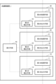
- the optical communication device 2 includes a plurality of optical signal processing units 100 and receiving means 140 .
- a plurality of optical signal processing units 100 are provided on one optical path.
- the optical signal processing unit 100 comprises processing means 110 , output means 120 and detection means 130 .
- the processing means 110 processes the input optical signal.
- the output means 120 outputs the optical signal processed by the processing means 110 .
- the detection means 130 detects anomalies in the optical signal at the output means 120 . When detecting an abnormality in the optical signal, the detection means 130 notifies the reception means 140 of the abnormality in the optical signal.
- the reception unit 140 receives notifications of optical signal abnormalities from the detection units 130 in the plurality of optical signal processing units 100 and outputs them to the outside.
- the receiving unit 140 receives from a specific optical signal processing unit 100 out of the plurality of optical signal processing units 100 a next-stage optical signal processing unit 100 connected to a subsequent stage on the optical path of the specific optical signal processing unit 100.
- Stores the mask settings set by The reception unit 40 receives an abnormality from the detection unit 130 provided in the optical signal processing unit 100 with mask setting based on the mask setting set from the optical signal processing unit 100 having the detection unit 130 that has detected the abnormality. is not output to the outside, and the abnormality notification from the detecting means 130 provided in the optical signal processing unit 100 in which the mask setting is not performed is output to the outside.
- FIG. 7 is a flow chart showing an operation example of the optical communication device 2 .
- the reception unit 140 receives an abnormality notification from the detection unit provided in the optical signal processing unit with the mask setting based on the mask setting set by the optical signal processing unit 100 having the detection unit 130 that detected the abnormality. is not output to the outside, and an abnormality notification from the detection means provided in the optical signal processing unit that is not masked is output to the outside (S201).
- the next-stage optical signal processing unit 100 connected to the subsequent stage of the specific optical signal processing unit 100 having the detection means 130 that has detected an abnormality has mask settings. It is The reception unit 140 does not output to the outside the notification of abnormality from the detection unit 130 provided in the optical signal processing unit 100 with the mask setting, and is provided in the optical signal processing unit 100 without the mask setting. The abnormality notification from the detection means 130 is output to the outside. Therefore, even if the connection relationship of the optical signal processing units 100 of the optical communication device 2 is switched, the reception unit 140 receives the optical signal at the frontmost stage among the plurality of optical signal processing units 100 having the detection unit 130 that has notified the abnormality. Only the notification from the detection means 130 provided in the processing unit 100 is output to the outside. That is, according to the optical communication device 2 , it is possible to set a mask according to the combination of the optical signal processing units inside the optical communication device 2 .
Landscapes
- Physics & Mathematics (AREA)
- Electromagnetism (AREA)
- Engineering & Computer Science (AREA)
- Computer Networks & Wireless Communication (AREA)
- Signal Processing (AREA)
- Optical Communication System (AREA)
Priority Applications (3)
| Application Number | Priority Date | Filing Date | Title |
|---|---|---|---|
| US18/294,800 US20240348331A1 (en) | 2021-08-20 | 2021-08-20 | Optical communication device and control method for optical communication device |
| PCT/JP2021/030520 WO2023021679A1 (ja) | 2021-08-20 | 2021-08-20 | 光通信装置、光通信装置の制御方法 |
| JP2023542147A JPWO2023021679A1 (https=) | 2021-08-20 | 2021-08-20 |
Applications Claiming Priority (1)
| Application Number | Priority Date | Filing Date | Title |
|---|---|---|---|
| PCT/JP2021/030520 WO2023021679A1 (ja) | 2021-08-20 | 2021-08-20 | 光通信装置、光通信装置の制御方法 |
Publications (1)
| Publication Number | Publication Date |
|---|---|
| WO2023021679A1 true WO2023021679A1 (ja) | 2023-02-23 |
Family
ID=85240431
Family Applications (1)
| Application Number | Title | Priority Date | Filing Date |
|---|---|---|---|
| PCT/JP2021/030520 Ceased WO2023021679A1 (ja) | 2021-08-20 | 2021-08-20 | 光通信装置、光通信装置の制御方法 |
Country Status (3)
| Country | Link |
|---|---|
| US (1) | US20240348331A1 (https=) |
| JP (1) | JPWO2023021679A1 (https=) |
| WO (1) | WO2023021679A1 (https=) |
Citations (2)
| Publication number | Priority date | Publication date | Assignee | Title |
|---|---|---|---|---|
| JPH08298533A (ja) * | 1995-04-25 | 1996-11-12 | Fujitsu Ltd | アラーム収集装置 |
| JPH09116517A (ja) * | 1995-10-20 | 1997-05-02 | Fujitsu Ltd | アラーム処理装置及び方法並びに伝送装置 |
-
2021
- 2021-08-20 JP JP2023542147A patent/JPWO2023021679A1/ja active Pending
- 2021-08-20 US US18/294,800 patent/US20240348331A1/en active Pending
- 2021-08-20 WO PCT/JP2021/030520 patent/WO2023021679A1/ja not_active Ceased
Patent Citations (2)
| Publication number | Priority date | Publication date | Assignee | Title |
|---|---|---|---|---|
| JPH08298533A (ja) * | 1995-04-25 | 1996-11-12 | Fujitsu Ltd | アラーム収集装置 |
| JPH09116517A (ja) * | 1995-10-20 | 1997-05-02 | Fujitsu Ltd | アラーム処理装置及び方法並びに伝送装置 |
Also Published As
| Publication number | Publication date |
|---|---|
| US20240348331A1 (en) | 2024-10-17 |
| JPWO2023021679A1 (https=) | 2023-02-23 |
Similar Documents
| Publication | Publication Date | Title |
|---|---|---|
| US8483560B2 (en) | Optical communication apparatus and optical wavelength multiplexing transmission system | |
| CN114397093A (zh) | 一种光纤激光器功率监测系统及安全联锁方法 | |
| WO2023021679A1 (ja) | 光通信装置、光通信装置の制御方法 | |
| JP6031870B2 (ja) | 光増幅器及び光信号の異常検出方法 | |
| JP2011243803A (ja) | 光ファイバ増幅装置、及び該光ファイバ増幅装置における光信号増幅方法 | |
| JPH1049788A (ja) | ガス圧力及びガス漏出感知システム | |
| US20220307871A1 (en) | Optical fiber sensing system and optical fiber sensing method | |
| JP2012151313A (ja) | ファイバ光増幅器 | |
| JP2010041195A (ja) | 光通信装置及び光出力制御方法及び光通信システム及びプログラム | |
| JP2000209151A (ja) | 光増幅中継装置及び複数心双方向光伝送システム | |
| KR101866278B1 (ko) | 다중제어 음향시스템 | |
| KR101284058B1 (ko) | Pll 회로를 이용한 전관방송 시스템 | |
| JP5191959B2 (ja) | 光伝送システム | |
| JPH0521872A (ja) | 光増幅器および光伝送システム | |
| JP2004014760A (ja) | 光増幅器 | |
| JP4663597B2 (ja) | 非常放送設備用スピーカ特性補正装置 | |
| JP5087430B2 (ja) | 中継器、光伝送システム及びその切替方法 | |
| JP5752576B2 (ja) | 光伝送システム | |
| KR100954219B1 (ko) | 지능형 정보표시 시스템 및 그 정보표시 방법 | |
| JPH0195611A (ja) | 共通増幅回路 | |
| JP2010245758A (ja) | 警報音発生機能付スピーカアンプ | |
| KR20060028987A (ko) | 반도체 제조 장비의 음성 경고 장치 | |
| JP2008244024A (ja) | レーザー出力断警報の保持システム | |
| JPH06347841A (ja) | 光増幅中継器 | |
| JP2008158967A (ja) | 多段式ビームセンサ |
Legal Events
| Date | Code | Title | Description |
|---|---|---|---|
| WWE | Wipo information: entry into national phase |
Ref document number: 2023542147 Country of ref document: JP |
|
| WWE | Wipo information: entry into national phase |
Ref document number: 18294800 Country of ref document: US |
|
| NENP | Non-entry into the national phase |
Ref country code: DE |
|
| 122 | Ep: pct application non-entry in european phase |
Ref document number: 21954247 Country of ref document: EP Kind code of ref document: A1 |