WO2023017587A1 - 二次電池用材料、負極活物質および二次電池 - Google Patents
二次電池用材料、負極活物質および二次電池 Download PDFInfo
- Publication number
- WO2023017587A1 WO2023017587A1 PCT/JP2021/029652 JP2021029652W WO2023017587A1 WO 2023017587 A1 WO2023017587 A1 WO 2023017587A1 JP 2021029652 W JP2021029652 W JP 2021029652W WO 2023017587 A1 WO2023017587 A1 WO 2023017587A1
- Authority
- WO
- WIPO (PCT)
- Prior art keywords
- secondary battery
- negative electrode
- electrode active
- battery material
- active material
- Prior art date
- Legal status (The legal status is an assumption and is not a legal conclusion. Google has not performed a legal analysis and makes no representation as to the accuracy of the status listed.)
- Ceased
Links
Images


Classifications
-
- H—ELECTRICITY
- H01—ELECTRIC ELEMENTS
- H01M—PROCESSES OR MEANS, e.g. BATTERIES, FOR THE DIRECT CONVERSION OF CHEMICAL ENERGY INTO ELECTRICAL ENERGY
- H01M10/00—Secondary cells; Manufacture thereof
- H01M10/05—Accumulators with non-aqueous electrolyte
- H01M10/052—Li-accumulators
- H01M10/0525—Rocking-chair batteries, i.e. batteries with lithium insertion or intercalation in both electrodes; Lithium-ion batteries
-
- H—ELECTRICITY
- H01—ELECTRIC ELEMENTS
- H01M—PROCESSES OR MEANS, e.g. BATTERIES, FOR THE DIRECT CONVERSION OF CHEMICAL ENERGY INTO ELECTRICAL ENERGY
- H01M4/00—Electrodes
- H01M4/02—Electrodes composed of, or comprising, active material
- H01M4/36—Selection of substances as active materials, active masses, active liquids
- H01M4/362—Composites
-
- H—ELECTRICITY
- H01—ELECTRIC ELEMENTS
- H01M—PROCESSES OR MEANS, e.g. BATTERIES, FOR THE DIRECT CONVERSION OF CHEMICAL ENERGY INTO ELECTRICAL ENERGY
- H01M4/00—Electrodes
- H01M4/02—Electrodes composed of, or comprising, active material
- H01M4/36—Selection of substances as active materials, active masses, active liquids
- H01M4/362—Composites
- H01M4/366—Composites as layered products
-
- C—CHEMISTRY; METALLURGY
- C01—INORGANIC CHEMISTRY
- C01B—NON-METALLIC ELEMENTS; COMPOUNDS THEREOF; METALLOIDS OR COMPOUNDS THEREOF NOT COVERED BY SUBCLASS C01C
- C01B32/00—Carbon; Compounds thereof
- C01B32/90—Carbides
- C01B32/907—Oxycarbides; Sulfocarbides; Mixture of carbides
-
- H—ELECTRICITY
- H01—ELECTRIC ELEMENTS
- H01M—PROCESSES OR MEANS, e.g. BATTERIES, FOR THE DIRECT CONVERSION OF CHEMICAL ENERGY INTO ELECTRICAL ENERGY
- H01M4/00—Electrodes
- H01M4/02—Electrodes composed of, or comprising, active material
- H01M4/13—Electrodes for accumulators with non-aqueous electrolyte, e.g. for lithium-accumulators; Processes of manufacture thereof
-
- H—ELECTRICITY
- H01—ELECTRIC ELEMENTS
- H01M—PROCESSES OR MEANS, e.g. BATTERIES, FOR THE DIRECT CONVERSION OF CHEMICAL ENERGY INTO ELECTRICAL ENERGY
- H01M4/00—Electrodes
- H01M4/02—Electrodes composed of, or comprising, active material
- H01M4/13—Electrodes for accumulators with non-aqueous electrolyte, e.g. for lithium-accumulators; Processes of manufacture thereof
- H01M4/134—Electrodes based on metals, Si or alloys
-
- H—ELECTRICITY
- H01—ELECTRIC ELEMENTS
- H01M—PROCESSES OR MEANS, e.g. BATTERIES, FOR THE DIRECT CONVERSION OF CHEMICAL ENERGY INTO ELECTRICAL ENERGY
- H01M4/00—Electrodes
- H01M4/02—Electrodes composed of, or comprising, active material
- H01M4/36—Selection of substances as active materials, active masses, active liquids
- H01M4/362—Composites
- H01M4/364—Composites as mixtures
-
- H—ELECTRICITY
- H01—ELECTRIC ELEMENTS
- H01M—PROCESSES OR MEANS, e.g. BATTERIES, FOR THE DIRECT CONVERSION OF CHEMICAL ENERGY INTO ELECTRICAL ENERGY
- H01M4/00—Electrodes
- H01M4/02—Electrodes composed of, or comprising, active material
- H01M4/36—Selection of substances as active materials, active masses, active liquids
- H01M4/38—Selection of substances as active materials, active masses, active liquids of elements or alloys
- H01M4/386—Silicon or alloys based on silicon
-
- H—ELECTRICITY
- H01—ELECTRIC ELEMENTS
- H01M—PROCESSES OR MEANS, e.g. BATTERIES, FOR THE DIRECT CONVERSION OF CHEMICAL ENERGY INTO ELECTRICAL ENERGY
- H01M4/00—Electrodes
- H01M4/02—Electrodes composed of, or comprising, active material
- H01M4/36—Selection of substances as active materials, active masses, active liquids
- H01M4/48—Selection of substances as active materials, active masses, active liquids of inorganic oxides or hydroxides
-
- H—ELECTRICITY
- H01—ELECTRIC ELEMENTS
- H01M—PROCESSES OR MEANS, e.g. BATTERIES, FOR THE DIRECT CONVERSION OF CHEMICAL ENERGY INTO ELECTRICAL ENERGY
- H01M4/00—Electrodes
- H01M4/02—Electrodes composed of, or comprising, active material
- H01M4/36—Selection of substances as active materials, active masses, active liquids
- H01M4/48—Selection of substances as active materials, active masses, active liquids of inorganic oxides or hydroxides
- H01M4/483—Selection of substances as active materials, active masses, active liquids of inorganic oxides or hydroxides for non-aqueous cells
-
- H—ELECTRICITY
- H01—ELECTRIC ELEMENTS
- H01M—PROCESSES OR MEANS, e.g. BATTERIES, FOR THE DIRECT CONVERSION OF CHEMICAL ENERGY INTO ELECTRICAL ENERGY
- H01M4/00—Electrodes
- H01M4/02—Electrodes composed of, or comprising, active material
- H01M4/36—Selection of substances as active materials, active masses, active liquids
- H01M4/58—Selection of substances as active materials, active masses, active liquids of inorganic compounds other than oxides or hydroxides, e.g. sulfides, selenides, tellurides, halogenides or LiCoFy; of polyanionic structures, e.g. phosphates, silicates or borates
- H01M4/583—Carbonaceous material, e.g. graphite-intercalation compounds or CFx
-
- H—ELECTRICITY
- H01—ELECTRIC ELEMENTS
- H01M—PROCESSES OR MEANS, e.g. BATTERIES, FOR THE DIRECT CONVERSION OF CHEMICAL ENERGY INTO ELECTRICAL ENERGY
- H01M4/00—Electrodes
- H01M4/02—Electrodes composed of, or comprising, active material
- H01M4/36—Selection of substances as active materials, active masses, active liquids
- H01M4/58—Selection of substances as active materials, active masses, active liquids of inorganic compounds other than oxides or hydroxides, e.g. sulfides, selenides, tellurides, halogenides or LiCoFy; of polyanionic structures, e.g. phosphates, silicates or borates
- H01M4/583—Carbonaceous material, e.g. graphite-intercalation compounds or CFx
- H01M4/587—Carbonaceous material, e.g. graphite-intercalation compounds or CFx for inserting or intercalating light metals
-
- H—ELECTRICITY
- H01—ELECTRIC ELEMENTS
- H01M—PROCESSES OR MEANS, e.g. BATTERIES, FOR THE DIRECT CONVERSION OF CHEMICAL ENERGY INTO ELECTRICAL ENERGY
- H01M4/00—Electrodes
- H01M4/02—Electrodes composed of, or comprising, active material
- H01M4/62—Selection of inactive substances as ingredients for active masses, e.g. binders, fillers
- H01M4/624—Electric conductive fillers
- H01M4/625—Carbon or graphite
-
- C—CHEMISTRY; METALLURGY
- C01—INORGANIC CHEMISTRY
- C01P—INDEXING SCHEME RELATING TO STRUCTURAL AND PHYSICAL ASPECTS OF SOLID INORGANIC COMPOUNDS
- C01P2002/00—Crystal-structural characteristics
- C01P2002/70—Crystal-structural characteristics defined by measured X-ray, neutron or electron diffraction data
- C01P2002/78—Crystal-structural characteristics defined by measured X-ray, neutron or electron diffraction data by stacking-plane distances or stacking sequences
-
- C—CHEMISTRY; METALLURGY
- C01—INORGANIC CHEMISTRY
- C01P—INDEXING SCHEME RELATING TO STRUCTURAL AND PHYSICAL ASPECTS OF SOLID INORGANIC COMPOUNDS
- C01P2002/00—Crystal-structural characteristics
- C01P2002/80—Crystal-structural characteristics defined by measured data other than those specified in group C01P2002/70
- C01P2002/82—Crystal-structural characteristics defined by measured data other than those specified in group C01P2002/70 by IR- or Raman-data
-
- C—CHEMISTRY; METALLURGY
- C01—INORGANIC CHEMISTRY
- C01P—INDEXING SCHEME RELATING TO STRUCTURAL AND PHYSICAL ASPECTS OF SOLID INORGANIC COMPOUNDS
- C01P2002/00—Crystal-structural characteristics
- C01P2002/80—Crystal-structural characteristics defined by measured data other than those specified in group C01P2002/70
- C01P2002/86—Crystal-structural characteristics defined by measured data other than those specified in group C01P2002/70 by NMR- or ESR-data
-
- C—CHEMISTRY; METALLURGY
- C01—INORGANIC CHEMISTRY
- C01P—INDEXING SCHEME RELATING TO STRUCTURAL AND PHYSICAL ASPECTS OF SOLID INORGANIC COMPOUNDS
- C01P2004/00—Particle morphology
- C01P2004/60—Particles characterised by their size
- C01P2004/61—Micrometer sized, i.e. from 1-100 micrometer
-
- C—CHEMISTRY; METALLURGY
- C01—INORGANIC CHEMISTRY
- C01P—INDEXING SCHEME RELATING TO STRUCTURAL AND PHYSICAL ASPECTS OF SOLID INORGANIC COMPOUNDS
- C01P2004/00—Particle morphology
- C01P2004/60—Particles characterised by their size
- C01P2004/62—Submicrometer sized, i.e. from 0.1-1 micrometer
-
- C—CHEMISTRY; METALLURGY
- C01—INORGANIC CHEMISTRY
- C01P—INDEXING SCHEME RELATING TO STRUCTURAL AND PHYSICAL ASPECTS OF SOLID INORGANIC COMPOUNDS
- C01P2004/00—Particle morphology
- C01P2004/80—Particles consisting of a mixture of two or more inorganic phases
-
- C—CHEMISTRY; METALLURGY
- C01—INORGANIC CHEMISTRY
- C01P—INDEXING SCHEME RELATING TO STRUCTURAL AND PHYSICAL ASPECTS OF SOLID INORGANIC COMPOUNDS
- C01P2006/00—Physical properties of inorganic compounds
- C01P2006/12—Surface area
-
- C—CHEMISTRY; METALLURGY
- C01—INORGANIC CHEMISTRY
- C01P—INDEXING SCHEME RELATING TO STRUCTURAL AND PHYSICAL ASPECTS OF SOLID INORGANIC COMPOUNDS
- C01P2006/00—Physical properties of inorganic compounds
- C01P2006/40—Electric properties
-
- H—ELECTRICITY
- H01—ELECTRIC ELEMENTS
- H01M—PROCESSES OR MEANS, e.g. BATTERIES, FOR THE DIRECT CONVERSION OF CHEMICAL ENERGY INTO ELECTRICAL ENERGY
- H01M4/00—Electrodes
- H01M4/02—Electrodes composed of, or comprising, active material
- H01M2004/021—Physical characteristics, e.g. porosity, surface area
-
- H—ELECTRICITY
- H01—ELECTRIC ELEMENTS
- H01M—PROCESSES OR MEANS, e.g. BATTERIES, FOR THE DIRECT CONVERSION OF CHEMICAL ENERGY INTO ELECTRICAL ENERGY
- H01M4/00—Electrodes
- H01M4/02—Electrodes composed of, or comprising, active material
- H01M2004/026—Electrodes composed of, or comprising, active material characterised by the polarity
- H01M2004/027—Negative electrodes
-
- Y—GENERAL TAGGING OF NEW TECHNOLOGICAL DEVELOPMENTS; GENERAL TAGGING OF CROSS-SECTIONAL TECHNOLOGIES SPANNING OVER SEVERAL SECTIONS OF THE IPC; TECHNICAL SUBJECTS COVERED BY FORMER USPC CROSS-REFERENCE ART COLLECTIONS [XRACs] AND DIGESTS
- Y02—TECHNOLOGIES OR APPLICATIONS FOR MITIGATION OR ADAPTATION AGAINST CLIMATE CHANGE
- Y02E—REDUCTION OF GREENHOUSE GAS [GHG] EMISSIONS, RELATED TO ENERGY GENERATION, TRANSMISSION OR DISTRIBUTION
- Y02E60/00—Enabling technologies; Technologies with a potential or indirect contribution to GHG emissions mitigation
- Y02E60/10—Energy storage using batteries
Definitions
- the present invention relates to a secondary battery material, a negative electrode active material containing the secondary battery material, and a secondary battery containing the negative electrode active material.
- Non-aqueous electrolyte secondary batteries are used in mobile devices, hybrid automobiles, electric automobiles, household storage batteries, etc., and are required to have well-balanced multiple characteristics such as electric capacity, safety, and operational stability. ing.
- a lithium intercalation compound that releases lithium ions from between layers is mainly used as a negative electrode material, and a carbon such as graphite that can intercalate and release lithium ions between crystal planes during charging and discharging.
- Patent Document 1 discloses a negative electrode active material for a secondary battery having a silicon oxide-based composite material in which scattering is observed in a specific range by X-ray small-angle scattering and Raman spectroscopy, and the intensity ratio of the Raman scattering peak is in a specific range. is disclosed.
- the silicon oxide-based composite material is represented by the general formula SiOxCy.
- Patent Document 2 discloses a SiOC composite material containing silicon element, oxygen element and carbon element in the form of fine particles, wherein the silicon particles are embedded in the SiOC matrix, the fine particles are formed of an amorphous SiOC matrix, and A SiOC composite material is disclosed having a core/coating structure with the core coated with at least one amorphous carbon layer.
- Patent Document 3 discloses a SiOC structure that is coated with at least one silicon-based fine particle and a SiOC coating layer containing at least Si, O, and C as constituent elements, and that has a specific surface area and a particle size that satisfy specific conditions. disclosed.
- Patent Document 4 discloses a method for producing a compound represented by the general formula SiOxCy using specific raw materials
- Patent Document 5 discloses a silicon-based inorganic compound composed of silicon, oxygen and carbon, and a silicon-based inorganic Compounds are disclosed that are characterized by the chemical bonding state of silicon present in the compound.
- the graphite-based negative electrode active material has a low initial capacity of the secondary battery, various improvements have been made for the purpose of increasing the capacity.
- the initial capacity of the silicon-containing active materials described in Patent Documents 1 to 5 can be increased.
- silicon-containing active materials are required to be further improved in capacity retention rate and battery life.
- the SiOC composite there was a tendency for the retention rate to decrease as the silicon content increased. Therefore, there is a demand for further improvement in the performance of negative electrode active materials used in secondary batteries.
- the present inventors focused on the ratio of silicon, oxygen, and carbon in the SiOC composite, and believed that it is possible to further improve the performance of the negative electrode active material of the secondary battery obtained by setting the composition ratio of these to a specific range.
- the present inventors have found that this is the case, and have completed the present invention. That is, the present invention relates to a secondary battery material used in a lithium ion battery, a negative electrode active material containing the secondary battery material, a secondary battery containing the negative electrode active material, and a charge/discharge capacity of the obtained secondary battery.
- An object of the present invention is to provide a secondary battery material that provides a secondary battery having overall high initial efficiency and capacity retention rate and excellent balance of these characteristics.
- the present invention has the following aspects.
- [1] Contains Si (silicon), O (oxygen), and C (carbon), wherein the content ratio x of O to Si is 0.1 ⁇ x ⁇ 2, and the content ratio y of C to Si is 0.3 ⁇ y ⁇ 11
- a secondary battery material [2] The secondary battery material according to [1] above, wherein 0.1 ⁇ x ⁇ 1.5 and 0.3 ⁇ y ⁇ 11.
- [3] The secondary battery material according to [1] or [2], wherein 0.1 ⁇ x ⁇ 1 and 0.3 ⁇ y ⁇ 11.
- [4] The secondary battery material according to any one of [1] to [3], wherein 0.1 ⁇ x ⁇ 0.7 and 0.3 ⁇ y ⁇ 11.
- the secondary battery material has, as chemical shift values obtained from the 29 Si-NMR spectrum, an area intensity A of a peak within the range of -70 ppm to -90 ppm attributed to Si (0 valence), and attributed to the SiO 4 bond.
- the secondary battery material according to any one of [1] to [10], wherein the area intensity B of the peak within the range of -90 ppm to -130 ppm satisfies the following formula (1).
- a negative electrode active material comprising the secondary battery material according to any one of [1] to [14].
- the negative electrode active material according to [18] wherein the material different from the secondary battery material is a carbon material.
- the negative electrode active material as a chemical shift value obtained from the 29 Si-NMR spectrum, is attributed to Si (0 valence), the area intensity A of the peak within the range of -70 ppm to -90 ppm, derived from the bond of SiO 4
- the negative electrode active material according to any one of [15] to [20] which has a volume average particle diameter (D50) of 0.5 ⁇ m to 10 ⁇ m.
- BET specific surface area
- a secondary battery comprising the negative electrode active material according to any one of [15] to [23].
- a negative electrode active material that provides a secondary battery having high charge/discharge capacity, initial efficiency, and capacity retention rate as a whole, and having an excellent balance of these characteristics, and a secondary battery used for the negative electrode active material Materials are provided.
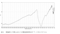
- FIG. 1 is a spectral diagram obtained by FT-IR measurement of the secondary battery material obtained in Example 1.
- FIG. FIG. 10 is a spectrum diagram obtained by FT-IR measurement of the secondary battery material obtained in Example 16.
- FIG. 10 is a spectrum diagram obtained by FT-IR measurement of the secondary battery material obtained in Example 26.
- the secondary battery material of the present invention contains Si (silicon), O (oxygen), and C (carbon), and the content ratio x of O to Si is 0.1 ⁇ x ⁇ 2, and the content ratio of C to Si. y is 0.3 ⁇ y ⁇ 11.
- the content ratio is the molar ratio of Si, O and C contained in the secondary battery material of the present invention. It is the number of moles of O contained in the battery material.
- y is the number of moles of C contained in the secondary battery material of the present invention per 1 mole of Si contained in the secondary battery material of the present invention.
- the content of O and C can be quantified by using an inorganic elemental analyzer, and the content of Si can be quantified by using an ICP optical emission spectrometer (ICP-OES).
- ICP-OES ICP optical emission spectrometer
- the molar ratio is preferably measured by the method described above, but the secondary battery material is locally analyzed, and a large number of measurement points of the content ratio data obtained thereby are obtained. It is also possible to analogize the content ratio of the entire secondary battery material. Local analysis includes, for example, Energy Dispersive X-ray Spectroscopy (SEM-EDX) and Electron Probe Microanalyzer (EPMA).
- SEM-EDX Energy Dispersive X-ray Spectroscopy
- EPMA Electron Probe Microanalyzer
- the secondary battery material of the present invention includes a matrix containing Si, O, and C and Si particles.
- the matrix contains a three-dimensional network structure of SiOC skeleton and free carbon.
- the free carbon referred to here is C that is not contained in the three-dimensional skeleton of SiOC, exists as a carbon phase, and is bonded between C in the carbon phase, and the SiOC skeleton and the carbon phase. contains C connecting
- it is considered that the Si particles are present in the matrix in a dispersed state.
- the SiOC skeleton in the matrix constituting the secondary battery material of the present invention is characterized by high chemical stability, and by forming a composite structure with free carbon, the electronic transition resistance is reduced and lithium ions diffuse. also becomes easier. Direct contact between the Si particles and the electrolytic solution is prevented by tightly enveloping the Si particles in the composite structure of the SiOC skeleton and free carbon. Therefore, the negative electrode active material containing the secondary battery material of the present invention avoids the chemical reaction between Si and the electrolyte during charging and discharging while the Si particles contained play a role of being the main component for the expression of charge and discharge performance. As a result, performance deterioration of the Si particles can be prevented to the maximum.
- SiOC the electron distribution inside SiOC changes due to the approach of lithium ions, and electrostatic bonds and coordinate bonds are formed between SiOC and lithium ions. stored in the skeleton of Since the energy of these coordination bonds is relatively low, the desorption reaction of lithium ions is easily carried out. In other words, it is considered that SiOC can reversibly cause lithium ion insertion/extraction reactions during charging and discharging.
- the Si particles in the matrix are zero-valent Si, and from the viewpoint of charge/discharge performance and initial coulomb efficiency when used as a negative electrode active material, the Si particles are preferably nanoparticles, and the secondary battery material is Si nanoparticles. It is preferably a complex containing
- the nanoparticles are particles having a volume average particle diameter of nano-order, preferably 10 nm to 300 nm, more preferably 20 nm to 250 nm, and even more preferably 30 nm to 200 nm. From the viewpoint of charge/discharge performance and capacity maintenance when used as a negative electrode active material, the volume average particle diameter of the Si nanoparticles is preferably 100 nm or less, more preferably 70 nm or less.
- the volume average particle size is a D50 value that can be measured using a laser diffraction particle size analyzer or the like. D50 can be measured by a dynamic light scattering method using a laser particle size analyzer or the like.
- D50 can be measured by a dynamic light scattering method using a laser particle size analyzer or the like.
- the particle size distribution of Si particles it is the particle size when the cumulative volume distribution curve is drawn from the small size side to 50%.
- Si particles having a large size exceeding 300 nm become large lumps, and when used as a negative electrode active material, the phenomenon of pulverization easily occurs during charging and discharging, so it is assumed that the capacity retention rate of the negative electrode active material tends to decrease.
- Si particles with a small size of less than 10 nm are too fine, the Si particles tend to agglomerate.
- the dispersibility of the Si particles in the negative electrode active material may deteriorate. Also, if the Si particles are too fine, the surface activation energy of the Si particles increases, and there is a tendency that by-products and the like tend to increase on the surfaces of the Si particles when the negative electrode active material is baked at high temperature. These may lead to deterioration in charge/discharge performance.
- the Si nanoparticles are obtained by pulverizing Si lumps into nano particles. Due to the presence of the Si nanoparticles, the charge/discharge capacity and the initial coulomb efficiency of the secondary battery can be improved.
- the pulverizer used for pulverizing the Si clumps into nanoparticles include pulverizers such as ball mills, bead mills, and jet mills.
- the pulverization may be wet pulverization using an organic solvent, and as the organic solvent, for example, alcohols, ketones, etc. can be preferably used. Group hydrocarbon solvents can also be used.
- the shape of the Si particles is not particularly limited, but from the viewpoint of charge/discharge performance when used as a negative electrode active material, the length in the major axis direction is preferably 70 to 300 nm, and the thickness is preferably 15 to 70 nm. From the viewpoint of charge/discharge performance when used as a negative electrode active material, the so-called aspect ratio, which is the ratio of thickness to length, is preferably 0.5 or less. Regarding the morphology of Si particles, the average particle size can be measured by a dynamic light scattering method. Samples of said aspect ratio can be more easily and precisely identified.
- the sample can be cut with a focused ion beam (FIB) and the cross section can be observed with FE-SEM, or the sample can be sliced and observed with TEM. can identify the state of the Si particles.
- the aspect ratio of the Si particles is a result of calculation based on 50 particles in the main portion of the sample within the field of view shown in the TEM image.
- the content ratio x of O to Si contained in the secondary battery material of the present invention is 0.1 ⁇ x ⁇ from the viewpoint that the balance between the charge / discharge performance and the capacity retention rate when used as a secondary battery is superior. 1.5 is preferred, 0.1 ⁇ x ⁇ 1.0 is more preferred, and 0.1 ⁇ x ⁇ 0.7 is even more preferred.
- the content ratio y of C to Si contained in the secondary battery material of the present invention is 0.3 ⁇ y ⁇ 11 from the viewpoint of the balance between the charge / discharge performance and the initial coulomb efficiency when used as a secondary battery.
- 0.3 ⁇ y ⁇ 8 is more preferable.
- the sum of the content ratio x and the content ratio y, x+y is preferably 1.2 or more, more preferably 2.3 or more.
- the secondary battery material of the present invention may contain nitrogen atoms and N in addition to the Si, O, and C described above.
- N is a raw material used in the method for producing a secondary battery material of the present invention, which will be described later, such as a phenol resin, a dispersant, a polysiloxane compound, other nitrogen compounds, and nitrogen gas used in the firing process, etc.
- a phenol resin a raw material used in the method for producing a secondary battery material of the present invention, which will be described later, such as a phenol resin, a dispersant, a polysiloxane compound, other nitrogen compounds, and nitrogen gas used in the firing process, etc.
- an atomic group containing N as a functional group, it can be introduced into the secondary battery material of the present invention. Since the secondary battery material of the present invention contains N, it tends to be excellent in charge/discharge performance and capacity retention rate when used as a negative electrode material.
- the content of N in the secondary battery material is preferably 0.1% by mass or more, with the total mass of Si, O, C and N being 100% by mass, from the viewpoint of charge/discharge performance and capacity retention rate. 0.5% by mass or more is more preferable, and 1% by mass or more is even more preferable. From the viewpoint of charge/discharge performance and capacity retention rate, it is preferably 5% by mass or less, more preferably 3% by mass or less, and even more preferably 2% by mass or less.
- the secondary battery material of the present invention preferably satisfies the following formula (1) in the chemical shift value obtained from the 29 Si-NMR spectrum. 0.2 ⁇ A/B ⁇ 5 (1)
- A is the area intensity of the peak within the range of -70 ppm to -90 ppm, which is attributed to Si (0 valence)
- B is the peak within the range of -90 ppm to -130 ppm, which is attributed to the bond of SiO represents the area intensity of
- the secondary battery material of the present invention has a structure in which Si particles are uniformly dispersed in a matrix containing a three-dimensional network structure of a SiOC skeleton made up of the elements Si, O, and C and free carbon. ing.
- the bonds can be mainly classified into three types according to the types of O or C atoms bonded to Si and the number of bonds with each atom. Domains with three types of bonds are SiO 2 C 2 , SiO 3 C, and SiO 4 , and silicon oxycarbide (SiOC) is formed by further randomly bonding these domains.
- the chemical shift (solid-state NMR) of the SiO 3 C domain is in the range of -60 ppm to -80 ppm with -70 ppm at the center position.
- the fact that the chemical shift value obtained from the 29 Si-NMR spectrum satisfies the above formula (1) means that the zero-valent Si particles and silicon oxycarbide in the secondary battery material
- the ratio of the existing SiO 4 is a ratio at which the Si particles are likely to exhibit performance, and the charge/discharge performance, especially the cycle characteristics, when used as a secondary battery is excellent.
- A/B is more preferably in the range of 0.8 ⁇ A/B ⁇ 2.9, and more preferably in the range of 0.9 ⁇ A/B ⁇ 2.8.
- 29 Si-NMR spectra are readily obtained using solid-state NMR equipment.
- solid-state NMR measurement is performed using, for example, an apparatus (JNM-ECA600) manufactured by JEOL Co., Ltd. JEOL.
- JNM-ECA600 manufactured by JEOL Co., Ltd. JEOL.
- the above A / B is obtained by performing a single pulse measurement with an 8 mm probe after 10 minutes of tuning with a solid-state NMR analyzer, Fourier transforming the obtained solid-state NMR spectrum data (accumulated 64 times), and applying the Gauss + Lorentz function.
- Waveform separation is performed using Next, based on the peak area obtained by waveform separation, the area intensity of the peak in the range of -90 ppm to -130 ppm, B, the area intensity of the peak in the range of -70 ppm to -90 ppm, A, It is obtained by calculating the ratio.
- the average particle size (D50) of the secondary battery material of the present invention is preferably from 0.5 ⁇ m to 10 ⁇ m, more preferably from 2 ⁇ m to 8 ⁇ m. If D50 is too small, the amount of solid-phase interface electrolyte decomposition product (hereinafter also referred to as "SEI") generated during charging and discharging in a secondary battery increases as the specific surface area increases significantly, resulting in an increase in the amount per unit volume. The reversible charge/discharge capacity of the battery may decrease. If D50 is too large, there is a risk of separation from the current collector during electrode film production. The method for measuring D50 is the same as described above. Further, the particle size range of the secondary battery material of the present invention before classification is preferably 0.1 ⁇ m to 30 ⁇ m, and the particle size range after removing fine particles is preferably 0.5 ⁇ m to 30 ⁇ m.
- SEI solid-phase interface electrolyte decomposition product
- the specific surface area (BET) of the secondary battery material of the present invention is preferably in the range of 1 m 2 /g to 20 m 2 /g, more preferably in the range of 3 m 2 /g to 18 m 2 /g.
- the specific surface area (BET) can be determined by nitrogen gas adsorption measurement, and can be measured by using a specific surface area measuring device.
- the matrix has free carbon composed only of the C element together with the SiOC skeleton structure and the like.
- the carbon structure is attributed to the G band of the graphite long-period carbon lattice structure and the D band of the graphite short-period carbon lattice structure with disorder and defects at 1590 cm. It is preferable to have scattering peaks around -1 and 1330 cm -1 and have a scattering peak intensity ratio I (G band/D band) in the range of 0.7 to 2.
- the scattering peak intensity ratio I is more preferably 0.7 to 1.8.
- the fact that the scattering peak intensity ratio I is within the above range means that the free carbon in the matrix is as follows.
- Some C atoms of free carbon are bonded to some Si atoms in the SiOC skeleton. This free carbon is an important component that affects charge/discharge characteristics. Free carbon is mainly formed in the SiOC skeleton composed of SiO 2 C 2 , SiO 3 C, and SiO 4 , and since it is bonded to some Si atoms of the SiOC skeleton, SiOC Electron transfer between the Si atoms inside the skeleton and between the surface Si atoms and free carbon becomes easier. For this reason, it can be considered that the lithium ion insertion/extraction reaction during charge/discharge of the secondary battery progresses rapidly, and the charge/discharge characteristics are improved.
- the negative electrode active material may slightly expand or contract due to the insertion/extraction reaction of lithium ions, the presence of free carbon in the vicinity of the expansion/contraction of the active material as a whole mitigates the expansion/contraction. It is considered that there is an effect of greatly improving the capacity retention rate.
- Free carbon is formed by thermal decomposition of the precursor Si-containing compound and carbon source resin in an inert gas atmosphere when producing the secondary battery material of the present invention.
- carbonizable sites in the molecular structures of the Si-containing compound and the carbon source resin become carbon components by high-temperature pyrolysis in an inert atmosphere, and some of these carbons become part of the SiOC skeleton.
- the carbonizable component is preferably a hydrocarbon, more preferably alkyls, alkylenes, alkenes, alkynes, aromatics, and more preferably aromatics.
- the presence of free carbon is expected to reduce the resistance of the active material, and when it is used in the negative electrode of a secondary battery, the reaction inside the active material occurs uniformly and smoothly. It is considered that a secondary battery material having an excellent balance of It is possible to introduce free carbon only from a Si-containing compound. However, carbon compounds containing six-membered rings of carbon are preferred.
- the existence state of the free carbon can be identified by thermogravimetric differential thermal analysis (TG-DTA) as well as Raman spectrum. Unlike C atoms in the SiOC skeleton, free carbon is easily thermally decomposed in the air, and the amount of carbon present can be determined from the amount of thermogravimetric loss measured in the presence of air. That is, the carbon content can be quantified using TG-DTA.
- TG-DTA thermogravimetric differential thermal analysis
- changes in thermal decomposition temperature behavior such as decomposition reaction start temperature, decomposition reaction end temperature, number of thermal decomposition reaction species, temperature of maximum weight loss in each thermal decomposition reaction species, etc. Easy to grasp. The temperature values of these behaviors can be used to determine the state of the carbon.
- the C atoms in the SiOC skeleton that is, the carbon atoms bonded to the Si atoms constituting the SiO 2 C 2 , SiO 3 C, and SiO 4 have very strong chemical bonds and are therefore thermally stable. It is considered that it will not be thermally decomposed in the air within the temperature range measured by the thermal analyzer.
- the carbon in the secondary battery material of the present invention since the carbon in the secondary battery material of the present invention has properties similar to those of amorphous carbon, it is thermally decomposed in the atmosphere within a temperature range of about 550°C to 900°C. As a result, rapid weight loss occurs.
- the maximum temperature of the TG-DTA measurement conditions is not particularly limited, but TG-DTA measurement is performed in the air under conditions from about 25° C. to about 1000° C. or higher in order to completely complete the thermal decomposition reaction of carbon. is preferred.
- the true density of the secondary battery material of the present invention is preferably higher than 1.6 g/cm 3 and lower than 2.4 g/cm 3 . Also, the true density is preferably higher than 1.7 g/cm 3 and lower than 2.35 g/cm 3 .
- the true density is within the above range, the composition ratio and porosity of each component constituting the secondary battery material are within appropriate ranges, and when used as a negative electrode active material, charge/discharge performance is likely to be exhibited.
- the true density can be measured using a true density measuring device.
- the negative electrode active material of the present invention includes the secondary battery material of the present invention.
- the negative electrode active material of the present invention may be the secondary battery material itself, or may contain other necessary third components.
- the negative electrode active material of the present invention may include the secondary battery material whose surface is coated with a substance (hereinafter also referred to as “coating material”) different from the secondary battery material.
- the substance different from the secondary battery material is preferably a substance that can be expected to have electronic conductivity, lithium ion conductivity, and an effect of suppressing the decomposition of the electrolytic solution.
- the average thickness of the coating layer is preferably 10 nm or more and 300 nm or less.
- the average thickness is preferably 20 nm or more and 200 nm or less. Since the secondary battery material has a coating layer having the above average thickness, it is possible to protect the Si nanoparticles exposed on the particle surface. The chemical stability and thermal stability of the active material are improved. It is possible to further suppress the deterioration of the charge/discharge performance of the secondary battery obtained as a result. Further, when the surface of the secondary battery material is coated with the coating material, the content of the coating material is the total amount of the secondary battery material from the viewpoint of improving the chemical stability and thermal stability of the negative electrode active material.
- the total amount of the secondary battery material is the total amount of Si, O, C and the coating material that constitute the secondary battery material.
- the secondary battery material contains N it is the total amount including N.
- the coating material examples include electron conductive substances such as carbon, titanium, and nickel. Among these, from the viewpoint of improving the chemical stability and thermal stability of the negative electrode active material, carbon is preferable, and low-crystalline carbon is more preferable.
- the coating material is low-crystalline carbon, the average thickness of the coating layer is 10 nm or more and 300 nm or less, or the content of low-crystalline carbon is 1 to 30% by mass based on the total amount of the secondary battery material as 100% by mass. is preferred.
- the coating layer is preferably produced by chemical vapor deposition (CVD).
- CVD chemical vapor deposition
- the scattering peak intensity ratio I (G band/D band) of the Raman spectrum is preferably in the range of 0.9 to 1.1.
- the specific surface area (BET) is preferably 3.5 m 2 /g or less, and the true density is preferably 1.9 g/cm 3 or more.
- the chemical shift value obtained from the 29 Si-NMR spectrum of the negative electrode active material of the present invention preferably satisfies the following formula (2). 0.2 ⁇ A/B ⁇ 5 (2)
- A is the area intensity of the peak within the range of -70 ppm to -90 ppm, which is attributed to Si (0 valence)
- B is the peak within the range of -90 ppm to -130 ppm, which is attributed to the bond of SiO represents the area intensity of
- the fact that the chemical shift value obtained from the 29 Si-NMR spectrum satisfies the above formula (2) means that SiO 4 present in the zero-valent Si particles and silicon oxycarbide in the negative electrode active material is a ratio at which the Si particles are likely to exhibit performance, and the charge/discharge performance when used as a secondary battery, particularly the capacity retention rate, is excellent.
- A/B is more preferably in the range of
- the D50 of the negative electrode active material of the present invention is preferably 0.5 ⁇ m to 10 ⁇ m, more preferably 2 ⁇ m to 8 ⁇ m. If D50 is too small, the reversible charge/discharge capacity per unit volume may decrease due to an increase in the amount of SEI generated during charging/discharging when used as a secondary battery as the specific surface area increases significantly. , there is a risk of peeling off from the current collector during electrode film fabrication.
- the method for measuring D50 is the same as described above.
- the specific surface area (BET) of the negative electrode active material of the present invention is preferably in the range of 1 m 2 /g to 20 m 2 /g, more preferably in the range of 3 m 2 /g to 18 m 2 /g.
- the specific surface area (BET) is within the above range, the amount of solvent absorbed during electrode production can be appropriately maintained, and the amount of binder used for maintaining binding properties can also be properly maintained.
- the method for measuring the specific surface area (BET) is the same as described above.
- a secondary battery using the negative electrode active material of the present invention as a battery negative electrode exhibits good charge/discharge characteristics.
- a slurry comprising the negative electrode active material of the present invention, an organic binder, and optionally other components such as a conductive aid is applied to a current collector copper foil like a thin film. It can be used as a negative electrode.
- a negative electrode can also be produced by adding a carbon material such as graphite to the slurry. Carbon materials include natural graphite, artificial graphite, amorphous carbon such as hard carbon or soft carbon, and the like.
- the negative electrode obtained as described above contains the negative electrode active material of the present invention, it becomes a negative electrode for a secondary battery that has a high capacity, an excellent capacity retention rate, and an excellent initial coulombic efficiency.
- the negative electrode is prepared, for example, by kneading the negative electrode active material for a secondary battery of the present invention and a binder, which is an organic binder, together with a solvent using a dispersing device such as a stirrer, ball mill, super sand mill, or pressure kneader. It can be obtained by preparing a negative electrode material slurry and coating it on a current collector to form a negative electrode layer. It can also be obtained by forming a paste-like negative electrode material slurry into a sheet-like or pellet-like shape and integrating this with a current collector.
- organic binder examples include styrene-butadiene rubber copolymer (SBR); methyl (meth) acrylate, ethyl (meth) acrylate, butyl (meth) acrylate, (meth) acrylonitrile, and hydroxyethyl (meth) Unsaturated carboxylic acids such as (meth)acrylic copolymers composed of ethylenically unsaturated carboxylic acid esters such as acrylates and ethylenically unsaturated carboxylic acids such as acrylic acid, methacrylic acid, itaconic acid, fumaric acid and maleic acid Copolymers; polymeric compounds such as polyvinylidene fluoride, polyethylene oxide, polyepichlorohydrin, polyphosphazene, polyacrylonitrile, polyimide, polyamideimide, and carboxymethyl cellulose (CMC).
- SBR styrene-butadiene rubber copolymer
- these organic binders can be dispersed or dissolved in water, or dissolved in an organic solvent such as N-methyl-2-pyrrolidone (NMP).
- NMP N-methyl-2-pyrrolidone
- the content ratio of the organic binder in the negative electrode layer of the lithium ion secondary battery negative electrode is preferably 1% by mass to 30% by mass, more preferably 2% by mass to 20% by mass, and 3% by mass. to 15% by mass is more preferable.
- the negative electrode active material of the present invention has high chemical stability and can be used with an aqueous binder, and is easy to handle in terms of practical use.
- the negative electrode material slurry may be mixed with a conductive aid, if necessary.
- conductive aids include carbon black, graphite, acetylene black, oxides and nitrides exhibiting conductivity, and the like.
- the amount of the conductive aid used may be about 1% by mass to 15% by mass with respect to the negative electrode active material of the present invention.
- the material and shape of the current collector for example, copper, nickel, titanium, stainless steel, etc. may be used in the form of a foil, a perforated foil, a mesh, or the like in a strip shape.
- Porous materials such as porous metal (foamed metal) and carbon paper can also be used.
- Examples of the method for applying the negative electrode material slurry to the current collector include a metal mask printing method, an electrostatic coating method, a dip coating method, a spray coating method, a roll coating method, a doctor blade method, a gravure coating method, and a screen printing method. etc. After coating, it is preferable to carry out a rolling treatment using a flat plate press, calendar rolls, or the like, if necessary.
- the negative electrode material slurry can be made into a sheet or pellet form, and this can be integrated with the current collector by, for example, rolling, pressing, or a combination thereof.
- the negative electrode layer formed on the current collector and the negative electrode layer integrated with the current collector are preferably heat-treated according to the organic binder used.
- the organic binder used For example, when a water-based styrene-butadiene rubber copolymer (SBR) or the like is used, heat treatment at 100 to 130° C. is sufficient, and when using an organic binder having a main skeleton of polyimide or polyamideimide, Heat treatment at 150 to 450° C. is preferred.
- SBR styrene-butadiene rubber copolymer
- This heat treatment removes the solvent and hardens the binder to increase the strength, improving the adhesion between particles and between the particles and the current collector.
- These heat treatments are preferably performed in an inert atmosphere such as helium, argon, or nitrogen, or in a vacuum atmosphere in order to prevent oxidation of the current collector during the treatment.
- the negative electrode using the negative electrode active material of the present invention preferably has an electrode density of 1 g/cm 3 to 1.8 g/cm 3 , more preferably 1.1 g/cm 3 to 1.7 g/cm 3 . It is preferably 1.2 g/cm 3 to 1.6 g/cm 3 , more preferably.
- the electrode density there is a tendency that the higher the electrode density, the better the adhesion and the volume capacity density of the electrode. Select the optimum range because the retention rate will decrease.
- a negative electrode containing the negative electrode active material of the present invention is suitable for use in secondary batteries because of its excellent charge-discharge characteristics.
- a secondary battery having such a negative electrode a non-aqueous electrolyte secondary battery and a solid electrolyte secondary battery are preferable, and excellent performance is exhibited particularly when used as a negative electrode of a non-aqueous electrolyte secondary battery.
- the secondary battery of the present invention when used as a wet electrolyte secondary battery, a positive electrode and a negative electrode containing the negative electrode active material of the present invention are placed facing each other with a separator interposed therebetween, and an electrolytic solution is injected. It can be configured by
- the positive electrode can be obtained by forming a positive electrode layer on the surface of the current collector in the same manner as the negative electrode.
- the current collector may be a strip-shaped one made of a metal or alloy such as aluminum, titanium, or stainless steel in the form of foil, foil with holes, mesh, or the like.
- the positive electrode material used for the positive electrode layer is not particularly limited.
- a metal compound, a metal oxide, a metal sulfide, or a conductive polymer material capable of doping or intercalating lithium ions should be used.
- lithium cobaltate LiCoO 2
- lithium nickelate LiNiO 2
- lithium manganate LiMnO 2
- lithium manganese spinel LiMn 2 O 4
- lithium vanadium compounds V2O5 , V6O13 , VO2 , MnO2
- TiO2 , MoV2O8 TiS2 , V2S5 , VS2
- olivine-type LiMPO 4 M: Co, Ni, Mn, Fe
- conductive polymers such as polyacetylene, polyaniline, polypyrrole, polythiophene, polyacene, etc., porous carbon, etc. are used singly or in combination. be able to.
- the separator for example, a non-woven fabric, cloth, microporous film, or a combination of them can be used, the main component of which is polyolefin such as polyethylene or polypropylene.
- the positive electrode and the negative electrode of the non-aqueous electrolyte secondary battery to be manufactured are structured such that they do not come into direct contact with each other, there is no need to use a separator.
- electrolytes examples include lithium salts such as LiClO 4 , LiPF 6 , LiAsF 6 , LiBF 4 and LiSO 3 CF 3 , ethylene carbonate, propylene carbonate, butylene carbonate, vinylene carbonate, fluoroethylene carbonate, cyclopentanone, sulfolane.
- the structure of the secondary battery of the present invention is not particularly limited, but usually, a positive electrode, a negative electrode, and an optional separator are wound into a flat spiral to form a wound electrode plate group. It is common to have a structure in which flat plates are laminated to form a laminated electrode plate group, and these electrode plate groups are enclosed in an outer package.
- the half-cell used in the examples of the present invention has a negative electrode composed mainly of the silicon-containing active material of the present invention, and a simple evaluation using metallic lithium as the counter electrode. This is to clearly compare the cycle characteristics.
- the negative electrode capacity is suppressed to about 400 to 700 mAh/g, which greatly exceeds the existing negative electrode capacity, and the cycle characteristics are improved. Is possible.
- the secondary battery using the negative electrode active material of the present invention is not particularly limited, but is used as a paper-type battery, a button-type battery, a coin-type battery, a laminate-type battery, a cylindrical battery, a square-type battery, and the like.
- the negative electrode active material of the present invention described above can also be applied to general electrochemical devices having a charging/discharging mechanism of intercalating and deintercalating lithium ions, such as hybrid capacitors and solid lithium secondary batteries.
- the secondary battery material of the present invention can be produced, for example, by a method including steps 1 to 3 below.
- steps 1 to 3 the following steps exemplify a method using a polysiloxane compound as the Si-containing compound, the method is not limited to these methods.
- Step 1 A Si (zero-valent) slurry pulverized by a wet method is mixed with an aggregate containing a polysiloxane compound and a carbon source resin, stirred and dried to obtain a precursor.
- Step 2 The precursor obtained in Step 1 is fired in an inert atmosphere at a maximum temperature of 1000° C. to 1180° C. to obtain a fired product.
- Step 3 The baked product obtained in step 2 is pulverized to obtain a secondary battery material.
- Step 1 Si (zero valent) slurry
- the wet-milled Si (zero-valent) slurry used in step 1 can be prepared while using an organic solvent and milling silicon particles with a wet powder mill.
- a dispersant may be used to facilitate the grinding of the silicon particles in the organic solvent.
- the wet pulverizer is not particularly limited, and includes roller mills, high-speed rotary pulverizers, container-driven mills, bead mills, and the like.
- the wet grinding preferably disperses the silicon particles until they become silicon nanoparticles.
- the organic solvent used in the wet method should not chemically react with silicon.
- examples thereof include ketones such as acetone, methyl ethyl ketone, methyl isobutyl ketone and diisobutyl ketone; alcohols such as ethanol, methanol, normal propyl alcohol and isopropyl alcohol; aromatic benzene, toluene and xylene.
- Aqueous or non-aqueous dispersants can be used for the types of dispersants described above. Use of a non-aqueous dispersant is preferred in order to suppress excessive oxidation of the surface of the silicon particles.
- Types of non-aqueous dispersants include polymer types such as polyethers, polyalkylene polyamines, polycarboxylic acid partial alkyl esters, low molecular types such as polyhydric alcohol esters and alkylpolyamines, and polyphosphates. is exemplified by the inorganic type of
- the concentration of silicon in the Si (zero-valent) slurry is not particularly limited. A range of from 40% by mass is preferable, and from 10% by mass to 30% by mass is more preferable.
- the polysiloxane compound used in step 1 is a resin containing at least one of a polycarbosilane structure, a polysilazane structure, a polysilane structure and a polysiloxane structure.
- a resin containing only these structures may be used, or a composite resin having at least one of these structures as a segment and chemically bonded to another polymer segment may be used.
- Forms of composite include graft copolymerization, block copolymerization, random copolymerization, alternating copolymerization, and the like.
- composite resins that have a graft structure in which polysiloxane segments and side chains of polymer segments are chemically bonded
- composite resins that have a block structure in which polysiloxane segments are chemically bonded to the ends of polymer segments. mentioned.
- the polysiloxane segment preferably has a structural unit represented by the following general formula (S-1) and/or the following general formula (S-2).
- the polysiloxane compound more preferably has a carboxy group, an epoxy group, an amino group, or a polyether group at the side chain or end of the siloxane bond (Si--O--Si) main skeleton.
- R 1 represents an aromatic hydrocarbon substituent or an alkyl group, an epoxy group, a carboxy group, etc.
- R 2 and R 3 each represent an alkyl group, Cycloalkyl group, aryl group, aralkyl group, epoxy group, carboxy group, etc.
- Alkyl groups include, for example, methyl group, ethyl group, propyl group, isopropyl group, butyl group, isobutyl group, sec-butyl group, tert-butyl group, pentyl group, isopentyl group, neopentyl group, tert-pentyl group, 1 -methylbutyl group, 2-methylbutyl group, 1,2-dimethylpropyl group, 1-ethylpropyl group, hexyl group, isohesyl group, 1-methylpentyl group, 2-methylpentyl group, 3-methylpentyl group, 1,1 -dimethylbutyl group, 1,2-dimethylbutyl group, 2,2-dimethylbutyl group, 1-ethylbutyl group, 1,1,2-trimethylpropyl group, 1,2,2-trimethylpropyl group, 1-ethyl- 2-methylpropyl group, 1-ethyl-1-methylpropyl group
- aryl groups include phenyl, naphthyl, 2-methylphenyl, 3-methylphenyl, 4-methylphenyl, 4-vinylphenyl, and 3-isopropylphenyl groups.
- the aralkyl group includes, for example, a benzyl group, a diphenylmethyl group, a naphthylmethyl group and the like.
- polymer segments other than the polysiloxane segment possessed by the polysiloxane compound include vinyl polymer segments such as acrylic polymers, fluoroolefin polymers, vinyl ester polymers, aromatic vinyl polymers, and polyolefin polymers, Examples include polymer segments such as polyurethane polymer segments, polyester polymer segments, and polyether polymer segments. Among them, a vinyl polymer segment is preferred.
- the polysiloxane compound may be a composite resin in which polysiloxane segments and polymer segments are bonded in a structure represented by the following structural formula (S-3), or may have a three-dimensional network-like polysiloxane structure.
- the carbon atom is the carbon atom that constitutes the polymer segment, and the two silicon atoms are the silicon atoms that constitute the polysiloxane segment.
- the polysiloxane segment of the polysiloxane compound may have a functional group capable of reacting by heating, such as a polymerizable double bond, in the polysiloxane segment.
- a functional group capable of reacting by heating such as a polymerizable double bond
- the cross-linking reaction proceeds and the polysiloxane compound is solidified, thereby facilitating the thermal decomposition treatment.
- polymerizable double bonds examples include vinyl groups and (meth)acryloyl groups. Two or more polymerizable double bonds are preferably present in the polysiloxane segment, more preferably 3 to 200, and even more preferably 3 to 50. In addition, by using a composite resin having two or more polymerizable double bonds as the polysiloxane compound, the cross-linking reaction can be facilitated.
- the polysiloxane segment may have silanol groups and/or hydrolyzable silyl groups.
- Hydrolyzable groups in hydrolyzable silyl groups include, for example, halogen atoms, alkoxy groups, substituted alkoxy groups, acyloxy groups, phenoxy groups, mercapto groups, amino groups, amido groups, aminooxy groups, iminooxy groups, alkenyloxy and the like, and the hydrolyzable silyl group becomes a silanol group by hydrolysis of these groups.
- a hydrolytic condensation reaction proceeds between the hydroxyl group in the silanol group and the hydrolyzable group in the hydrolyzable silyl group, thereby obtaining a solid polysiloxane compound. can.
- the silanol group referred to in the present invention is a silicon-containing group having a hydroxyl group directly bonded to a silicon atom.
- the hydrolyzable silyl group referred to in the present invention is a silicon-containing group having a hydrolyzable group directly bonded to a silicon atom. Specifically, for example, a group represented by the following general formula (S-4) is mentioned.
- R4 represents a monovalent organic group such as an alkyl group, an aryl group or an aralkyl group
- R5 represents a halogen atom, an alkoxy group, an acyloxy group, an allyloxy group, a mercapto group, an amino group, an amido group, an aminooxy group, iminooxy group or alkenyloxy group
- b is an integer of 0 to 2.
- Alkyl groups include, for example, methyl group, ethyl group, propyl group, isopropyl group, butyl group, isobutyl group, sec-butyl group, tert-butyl group, pentyl group, isopentyl group, neopentyl group, tert-pentyl group, 1 -methylbutyl group, 2-methylbutyl group, 1,2-dimethylpropyl group, 1-ethylpropyl group, hexyl group, isohesyl group, 1-methylpentyl group, 2-methylpentyl group, 3-methylpentyl group, 1,1 -dimethylbutyl group, 1,2-dimethylbutyl group, 2,2-dimethylbutyl group, 1-ethylbutyl group, 1,1,2-trimethylpropyl group, 1,2,2-trimethylpropyl group, 1-ethyl- 2-methylpropyl group, 1-ethyl-1-methylpropyl group
- aryl groups include phenyl, naphthyl, 2-methylphenyl, 3-methylphenyl, 4-methylphenyl, 4-vinylphenyl, and 3-isopropylphenyl groups.
- the aralkyl group includes, for example, a benzyl group, a diphenylmethyl group, a naphthylmethyl group and the like.
- the halogen atom includes, for example, fluorine atom, chlorine atom, bromine atom, iodine atom and the like.
- alkoxy groups include methoxy, ethoxy, propoxy, isopropoxy, butoxy, sec-butoxy, and tert-butoxy groups.
- acyloxy groups include formyloxy, acetoxy, propanoyloxy, butanoyloxy, pivaloyloxy, pentanoyloxy, phenylacetoxy, acetoacetoxy, benzoyloxy, naphthoyloxy and the like.
- the allyloxy group includes, for example, phenyloxy, naphthyloxy and the like.
- alkenyloxy groups include vinyloxy, allyloxy, 1-propenyloxy, isopropenyloxy, 2-butenyloxy, 3-butenyloxy, 2-petenyloxy, 3-methyl-3-butenyloxy, 2 -hexenyloxy group and the like.
- Examples of the polysiloxane segment having the structural unit represented by the above general formula (S-1) and/or the above general formula (S-2) include those having the following structures.
- the polymer segment may have various functional groups as necessary to the extent that the effects of the present invention are not impaired.
- Such functional groups include, for example, carboxyl group, blocked carboxyl group, carboxylic anhydride group, tertiary amino group, hydroxyl group, blocked hydroxyl group, cyclocarbonate group, epoxy group, carbonyl group, primary amide group, secondary Amide, carbamate groups, functional groups represented by the following structural formula (S-5), and the like can be used.
- polymer segment may have polymerizable double bonds such as vinyl groups and (meth)acryloyl groups.
- the above polysiloxane compound is preferably produced, for example, by the methods shown in (1) to (3) below.
- a polymer segment containing a silanol group and/or a hydrolyzable silyl group is prepared in advance, and the polymer segment and the silanol group and/or the hydrolyzable silyl group are and a method of mixing with a silane compound containing a silane compound having a polymerizable double bond and performing a hydrolytic condensation reaction.
- a polymer segment containing a silanol group and/or a hydrolyzable silyl group is prepared in advance.
- Polysiloxane is also prepared in advance by subjecting a silane compound containing a silane compound having both a silanol group and/or a hydrolyzable silyl group and a polymerizable double bond to a hydrolytic condensation reaction. Then, a method of mixing the polymer segment and polysiloxane and performing a hydrolytic condensation reaction.
- a polysiloxane compound is obtained by the method described above.
- the polysiloxane compound include the Ceranate (registered trademark) series (organic/inorganic hybrid type coating resin; manufactured by DIC Corporation) and the Compoceran SQ series (silsesquioxane type hybrid; manufactured by Arakawa Chemical Industries, Ltd.).
- the carbon source resin used in the step 1 has good miscibility with the polysiloxane compound at the time of precursor preparation, and is carbonized by high temperature firing in an inert atmosphere, synthetic resins having aromatic functional groups, and natural chemical raw materials. is preferably used.
- Synthetic resins include thermoplastic resins such as polyvinyl alcohol and polyacrylic acid, and thermosetting resins such as phenol resin and furan resin.
- Natural chemical raw materials include heavy oils, especially tar pitches such as coal tar, light tar oil, medium tar oil, heavy tar oil, naphthalene oil, anthracene oil, coal tar pitch, pitch oil, mesophase pitch, and oxygen-crosslinked petroleum pitch. , heavy oil, etc., but the use of phenolic resin is more preferable from the viewpoint of inexpensive availability and removal of impurities.
- the carbon source resin is preferably a resin containing an aromatic hydrocarbon moiety
- the resin containing an aromatic hydrocarbon moiety is a phenol resin, an epoxy resin, or a thermosetting resin.
- phenolic resin, and the phenolic resin is preferably a resol type. Examples of phenolic resins include the Sumilite Resin series (resol-type phenolic resin, manufactured by Sumitomo Bakelite Co., Ltd.).
- the assembly containing the polysiloxane compound and the carbon source resin and the Si slurry are uniformly mixed and stirred, and then the solvent is removed and dried to obtain a negative electrode active material precursor (hereinafter also referred to as “precursor”). is obtained.
- the assembly containing the polysiloxane compound and the carbon source resin is preferably in a state in which the polysiloxane compound and the carbon source resin are uniformly mixed.
- the mixing is performed using a device having a dispersing/mixing function.
- a stirrer, an ultrasonic mixer, a premix disperser and the like can be used.
- a dryer, a reduced-pressure dryer, a spray dryer, or the like can be used for solvent removal and drying for the purpose of distilling off the organic solvent.
- the precursor contains 3% to 50% by mass of silicon particles that are Si (0 valent), 15% to 85% by mass of the solid content of the polysiloxane compound, and 3% to 70% by mass of the solid content of the carbon source resin. %, the solid content of the silicon particles is 8% to 40% by mass, the solid content of the polysiloxane compound is 20 to 70% by mass, and the solid content of the carbon source resin is 3% to 60% by mass. It is more preferable to contain.
- Step 2 the precursor obtained in step 1 above is calcined in an inert atmosphere at a maximum temperature of 1000° C. to 1180° C. to completely decompose the thermally decomposable organic components, and other
- the main component is made into a sintered product suitable for the secondary battery material of the present invention by precisely controlling the sintering conditions. Specifically, the raw material polysiloxane compound and carbon source resin are converted into a SiOC skeleton and free carbon by the energy of the high-temperature treatment.
- step 2 the precursor obtained in step 1 is fired in an inert atmosphere according to a firing program defined by the rate of temperature increase, holding time at a constant temperature, and the like.
- the maximum attainable temperature is the maximum temperature to be set, and strongly affects the structure and performance of the secondary battery material, which is the baked product.
- the maximum temperature is 1000° C. to 1180° C.
- the fine structure of the secondary battery material having the chemical bonding state of Si and C can be precisely controlled, and the silicon particles can be formed by excessively high temperature firing. Since oxidation can also be avoided, more excellent charge/discharge characteristics can be obtained.
- the calcination method is not particularly limited, but a reaction apparatus having a heating function may be used in an inert atmosphere, and continuous or batchwise processing is possible.
- a fluidized bed reactor, a rotary furnace, a vertical moving bed reactor, a tunnel furnace, a batch furnace, a rotary kiln, or the like can be appropriately selected as the firing apparatus according to the purpose.
- Step 3 is a step for obtaining the secondary battery material of the present invention by pulverizing the baked product obtained in the above step 2 and classifying if necessary.
- the pulverization may be carried out in one step until the target particle size is obtained, or may be carried out in several steps.
- the fired product is lumps or agglomerated particles of 10 mm or more and to produce an active material of 10 ⁇ m
- it is coarsely pulverized with a jaw crusher, roll crusher, etc. to make particles of about 1 mm, and then 100 ⁇ m with a glow mill, ball mill, etc. and pulverized to 10 ⁇ m with a bead mill, jet mill, or the like.
- Particles produced by pulverization may contain coarse particles, and in order to remove them, or to adjust the particle size distribution by removing fine powder, classification is performed.
- the classifier to be used may be a wind classifier, a wet classifier, or the like depending on the purpose, but when removing coarse particles, the classification method through a sieve is preferable because the purpose can be reliably achieved.
- the precursor mixture is controlled to have a shape close to the target particle size by spray drying or the like before the main firing and the main firing is performed in that shape, the pulverization step can of course be omitted.
- the secondary battery material of the present invention when used as a negative electrode active material, the charge/discharge capacity, initial efficiency, and capacity retention rate are generally high, and a negative electrode that provides a secondary battery with an excellent balance of these characteristics.
- An active material and a secondary battery material used for the negative electrode active material are provided.
- the secondary battery material obtained by the above method can be suitably used as a negative electrode active material.
- the obtained negative electrode active material can be used as a negative electrode by the method described above, and a secondary battery having the negative electrode can be obtained.
- the present invention is not limited to the configurations of the above embodiments.
- the secondary battery material of the present invention, the negative electrode active material containing the secondary battery material, and the secondary battery containing the negative electrode active material may be added with other arbitrary structures in the structures of the above embodiments. , may be replaced with any configuration that performs a similar function.
- the method for producing a secondary battery material of the present invention may additionally include any other step in the configuration of the embodiment, or may be replaced with any step that produces the same effect. good too.
- Si represents the same substance as "silicon”.
- the present invention will be described in detail below with reference to Examples, but the present invention is not limited to these.
- the half-cell used in the examples of the present invention has a negative electrode composed mainly of the silicon-containing active material of the present invention, and a simple evaluation using metallic lithium as the counter electrode. This is to clearly compare the cycle characteristics.
- a negative electrode composed mainly of the silicon-containing active material of the present invention
- a simple evaluation using metallic lithium as the counter electrode. This is to clearly compare the cycle characteristics.
- the negative electrode capacity is suppressed to about 400 to 700 mAh/g, which greatly exceeds the existing negative electrode capacity, and the cycle characteristics are improved. is possible.
- the condensate obtained by the above hydrolytic condensation reaction is distilled under reduced pressure at a temperature of 40 to 60 ° C. until the reduced pressure condition at the start of distillation of methanol is 40 kPa and finally 1.3 kPa, and the above reaction
- 1,000 parts by mass of a liquid containing 70% by mass of the active ingredient was obtained, which contained the condensate (a1) of MTMS with a number average molecular weight of 1,000.
- MMA methyl methacrylate
- BMA butyl methacrylate
- BA butyric acid
- MPTS methacryloyloxypropyltrimethoxysilane
- TPEH butylperoxy-2-ethylhexanoate
- a liquid containing a composite resin was obtained in which the hydrolyzable silyl groups of the coalescence (a2-1) and the hydrolyzable silyl groups and silanol groups of the PTMS- and DMDMS-derived polysiloxanes were bonded.
- the resulting hydrolytic condensation reaction was stirred at temperature for 15 hours and distilled under the same conditions as in Synthesis Example 1 to remove the produced methanol and water, then 250 parts by mass of n-BuOH was added, 1,000 parts by mass of a curable resin composition (2) having a non-volatile content of 60.0% by mass was obtained.
- a negative electrode active material of the present invention was produced as follows. Zirconia beads (particle size range: 0.1 mm to 0.2 mm) and 400 ml of methyl ethyl ketone solvent (MEK) were placed in a container (150 ml) of a small bead mill device (Ultra Apex Mill UAM-015, manufactured by Hiroshima Metal & Machinery Co., Ltd.).
- MEK methyl ethyl ketone solvent
- Si powder manufactured by Wako Pharmaceutical Co., Ltd., average particle size 3 to 5 ⁇ m
- a predetermined amount of cationic dispersant liquid BYK145, BYK-Chemie Japan Co., Ltd.
- a Si slurry was obtained which was in the form of a dark brown liquid.
- the average particle size (D50) of the ground Si particles was 60 nm by light scattering measurement and TEM observation.
- Elemental analysis of the obtained negative electrode active material powder revealed that the composition ratio (molar ratio) of Si, O and C was 1:1.5:8.7.
- the analysis of each element was measured using the following equipment.
- the O content was measured using an oxygen/hydrogen/nitrogen analyzer (TCH-600, manufactured by LECO), and the C content was measured using a carbon/sulfur analyzer (CS844, manufactured by LECO).
- the Si content was measured using an ICP-OES analyzer (Agilent 5110 ICP-OES, manufactured by Agilent Technologies).
- the average particle diameter (D50) was about 5.7 ⁇ m
- the specific surface area (BET) was 27.1 m 2 /g.
- a half cell and a full cell were produced by the following method, and a secondary battery charge/discharge test was performed.
- a mixed slurry of an active material powder (80 parts), a conductive aid (acetylene black, 10 parts) and a binder (CMC+SBR, 10 parts) was prepared and formed into a film on a copper foil. After that, it was dried under reduced pressure at 110° C., and a Li metal foil was used as a counter electrode to prepare a half cell.
- This half cell was evaluated for charge/discharge characteristics using a secondary battery charge/discharge tester (manufactured by Hokuto Denko Co., Ltd.) (cutoff voltage range: 0.005 to 1.5 V).
- the charge and discharge measurement results were an initial discharge capacity of 1030 mAh/g and an initial (coulombic) efficiency of 79.0%.
- a positive electrode film was prepared using a single-layer sheet using LiCoO 2 as a positive electrode active material and aluminum foil as a current collector. Further, a negative electrode film was produced by mixing graphite powder or active material powder with a binder at a discharge capacity design value of 450 mAh/g.
- a non-aqueous electrolyte solution prepared by dissolving lithium hexafluorophosphate in a 1/1 (volume ratio) mixed solution of ethylene carbonate and diethyl carbonate at a concentration of 1 mol/L was used as the non-aqueous electrolyte, and polyethylene having a thickness of 30 ⁇ m was used as the separator.
- a full-cell coin-type lithium-ion secondary battery was fabricated using a microporous film made by This lithium ion secondary battery is charged at room temperature at a constant current of 1.2 mA (0.25 c based on the positive electrode) until the voltage of the test cell reaches 4.2 V, and after reaching 4.2 V, the cell Charging was performed by decreasing the current so as to keep the voltage at 4.2 V, and the discharge capacity was obtained.
- the capacity retention rate after 100 cycles at room temperature was 97%.
- Example 2 [Examples 2 to 41 and Comparative Examples 1 to 4]
- the curable resin composition (Synthesis Examples 1 to 3), phenolic resin (SUMILITE RESIN PR-53416) and Si slurry were changed as shown in Table 1.
- the Si powder was wet-pulverized for 3 hours
- Comparative Example 4 the Si powder was wet-pulverized for 1 hour
- zirconia beads with a particle size of about 2 mm were used.
- a negative electrode active material was obtained in the same manner as above.
- FT-IR measurement of the secondary battery materials obtained in Examples 1, 16 and 26 was performed under the conditions described below. The spectral diagrams obtained are shown in FIGS. 1 to 3.
- FIG. 1 to 3 the curable resin composition
- phenolic resin SUMILITE RESIN PR-53416
- Si slurry were changed as shown in Table 1.
- the Si powder was wet-pulverized for 3 hours
- Comparative Example 4 the Si powder was wet-pulverized for 1 hour
- Examples 42 and 45 20 g of the black solid obtained in the same manner as in Example 1 was put into a CVD device (desktop rotary kiln: manufactured by Takasago Kogyo Co., Ltd.), and a mixed gas of 0.3 L / min ethylene gas and 0.7 L / min nitrogen gas was introduced at 850° C. for 1 hour in Example 42 and for 3 hours in Example 45, and the surface of the black solid was coated with carbon by chemical vapor deposition.
- the post-treatment carbon coverage was measured by a thermal analyzer and found to be 5% higher for Example 42 and 20% higher for Example 45 than the pre-treatment weight.
- Example 43 In Example 1, the curable resin composition (Synthesis Examples 1 to 3), phenolic resin (SUMILITE RESIN PR-53416) and Si slurry were changed as shown in Table 1, and a black solid was obtained in the same manner as in Example 42. A carbon coating treatment was applied to the surface of the object. Using the secondary battery materials obtained in Examples 2 to 42 and Comparative Examples 1 to 3 as they were as negative electrode active materials, secondary batteries were produced and evaluated in the same manner as in Example 1. The evaluation results are shown in Tables 2 and 3.
- each evaluation method is as follows.
- Volume average particle diameter (D50) Measured using a laser diffraction particle size distribution analyzer (Mastersizer 3000, manufactured by Malvern Panalytical).
- Specific surface area (BET) Measured by nitrogen adsorption measurement using a specific surface area measuring device (BELSORP-mini manufactured by BEL JAPAN).
- 29 Si-NMR JNM-ECA600 manufactured by JEOL RESONANCE was used.
- Battery characteristics evaluation Battery characteristics were measured using a secondary battery charge/discharge tester (manufactured by Hokuto Denko Co., Ltd.), room temperature 25 ° C., cutoff voltage range from 0.005 to 1.5 V, charge/discharge rate 0
- the charging/discharging characteristics were evaluated under the conditions of constant current/constant voltage charge/constant current discharge at .1C (1 to 3 times) and 0.2C (after 4 cycles). At the time of switching between charging and discharging, the battery was left in an open circuit for 30 minutes.
- Initial coulombic efficiency and cycle characteristics (in the present application, refer to capacity retention rate at 100 cycles) were obtained as follows.
- FT-IR measurement FT/IR-4200 (manufactured by JASCO Corporation) was used as a measuring instrument.
- a tablet sample for measurement was prepared by mixing the measurement sample and KBr, and the measurement was carried out in the range of 4000 to 400 cm ⁇ 1 by the transmission method.
- Raman scattering spectrum measurement NRS-5500 (manufactured by JASCO Corporation) was used as a measuring instrument. The measurement conditions were an excitation laser wavelength of 532 nm, an objective lens magnification of 100, and a measurement wavenumber range of 3500 to 100 cm ⁇ 1 .
- the secondary battery material of the present invention when used as a negative electrode active material, the charge/discharge capacity, initial efficiency, and capacity retention rate are generally high, and these properties are well balanced.
- a secondary battery containing the negative electrode active material of the present invention is excellent in battery characteristics.
Landscapes
- Chemical & Material Sciences (AREA)
- Chemical Kinetics & Catalysis (AREA)
- Electrochemistry (AREA)
- General Chemical & Material Sciences (AREA)
- Engineering & Computer Science (AREA)
- Inorganic Chemistry (AREA)
- Composite Materials (AREA)
- Materials Engineering (AREA)
- Manufacturing & Machinery (AREA)
- Organic Chemistry (AREA)
- Battery Electrode And Active Subsutance (AREA)
Priority Applications (7)
| Application Number | Priority Date | Filing Date | Title |
|---|---|---|---|
| PCT/JP2021/029652 WO2023017587A1 (ja) | 2021-08-11 | 2021-08-11 | 二次電池用材料、負極活物質および二次電池 |
| CN202280056090.9A CN117882213A (zh) | 2021-08-11 | 2022-06-30 | 二次电池用材料、负极活性物质及二次电池 |
| KR1020247007712A KR20240042054A (ko) | 2021-08-11 | 2022-06-30 | 이차 전지용 재료, 음극 활물질 및 이차 전지 |
| PCT/JP2022/026169 WO2023017694A1 (ja) | 2021-08-11 | 2022-06-30 | 二次電池用材料、負極活物質および二次電池 |
| EP22855758.3A EP4386903A4 (en) | 2021-08-11 | 2022-06-30 | SECONDARY BATTERY MATERIAL, NEGATIVE ELECTRODE ACTIVE MATERIAL AND SECONDARY BATTERY |
| US18/682,611 US20250132314A1 (en) | 2021-08-11 | 2022-06-30 | Secondary battery material, negative electrode active material, and secondary battery |
| JP2023527018A JP7343081B2 (ja) | 2021-08-11 | 2022-06-30 | 二次電池用材料、負極活物質および二次電池 |
Applications Claiming Priority (1)
| Application Number | Priority Date | Filing Date | Title |
|---|---|---|---|
| PCT/JP2021/029652 WO2023017587A1 (ja) | 2021-08-11 | 2021-08-11 | 二次電池用材料、負極活物質および二次電池 |
Publications (1)
| Publication Number | Publication Date |
|---|---|
| WO2023017587A1 true WO2023017587A1 (ja) | 2023-02-16 |
Family
ID=85199931
Family Applications (2)
| Application Number | Title | Priority Date | Filing Date |
|---|---|---|---|
| PCT/JP2021/029652 Ceased WO2023017587A1 (ja) | 2021-08-11 | 2021-08-11 | 二次電池用材料、負極活物質および二次電池 |
| PCT/JP2022/026169 Ceased WO2023017694A1 (ja) | 2021-08-11 | 2022-06-30 | 二次電池用材料、負極活物質および二次電池 |
Family Applications After (1)
| Application Number | Title | Priority Date | Filing Date |
|---|---|---|---|
| PCT/JP2022/026169 Ceased WO2023017694A1 (ja) | 2021-08-11 | 2022-06-30 | 二次電池用材料、負極活物質および二次電池 |
Country Status (6)
| Country | Link |
|---|---|
| US (1) | US20250132314A1 (https=) |
| EP (1) | EP4386903A4 (https=) |
| JP (1) | JP7343081B2 (https=) |
| KR (1) | KR20240042054A (https=) |
| CN (1) | CN117882213A (https=) |
| WO (2) | WO2023017587A1 (https=) |
Cited By (1)
| Publication number | Priority date | Publication date | Assignee | Title |
|---|---|---|---|---|
| JPWO2023162692A1 (https=) * | 2022-02-25 | 2023-08-31 |
Families Citing this family (6)
| Publication number | Priority date | Publication date | Assignee | Title |
|---|---|---|---|---|
| JPWO2024181130A1 (https=) * | 2023-02-28 | 2024-09-06 | ||
| EP4704176A1 (en) * | 2023-04-26 | 2026-03-04 | Panasonic Intellectual Property Management Co., Ltd. | Negative electrode material for secondary battery, secondary battery, and method for manufacturing negative electrode material for secondary battery |
| WO2024224983A1 (ja) * | 2023-04-28 | 2024-10-31 | Dic株式会社 | 組成物、負極活物質、負極活物質の製造方法、及び二次電池 |
| KR20260009614A (ko) * | 2024-07-11 | 2026-01-20 | 주식회사 엘케이테크놀러지 | 이차전지 음극재용 실리콘 분말, 제조 방법 및 이차전지용 음극재 |
| CN121439696A (zh) * | 2024-07-30 | 2026-01-30 | 宁德时代新能源科技股份有限公司 | 锂离子电池单体、锂离子电池以及用电装置 |
| CN119314569B (zh) * | 2024-10-18 | 2025-11-04 | 中国科学院青岛生物能源与过程研究所 | 一种基于分子动力学模拟获取非晶SiOC原子离位能的模拟方法 |
Citations (4)
| Publication number | Priority date | Publication date | Assignee | Title |
|---|---|---|---|---|
| JP2020001941A (ja) * | 2018-06-25 | 2020-01-09 | Jnc株式会社 | コアシェル構造体及びその製造方法並びに該コアシェル構造体を負極活物質として用いた負極用組成物、負極及び二次電池 |
| JP2020017504A (ja) * | 2018-07-27 | 2020-01-30 | 荒川化学工業株式会社 | リチウムイオン電池電極用スラリー及びその製造方法、リチウムイオン電池用電極、並びにリチウムイオン電池 |
| JP2020138895A (ja) * | 2019-03-01 | 2020-09-03 | Jnc株式会社 | シリコン系微粒子/シリコン含有ポリマー複合体、SiOC構造体、並びにSiOC構造体を用いた負極用組成物、負極及び二次電池 |
| JP2021114483A (ja) * | 2018-12-19 | 2021-08-05 | Dic株式会社 | シリコンナノ粒子及びそれを用いた非水二次電池負極用活物質並びに二次電池 |
Family Cites Families (11)
| Publication number | Priority date | Publication date | Assignee | Title |
|---|---|---|---|---|
| WO2013031993A1 (ja) | 2011-08-31 | 2013-03-07 | 国立大学法人東北大学 | Si/C複合材料及びその製造方法並びに電極 |
| KR101357669B1 (ko) | 2011-09-22 | 2014-02-03 | 삼성에스디에스 주식회사 | 위치 기반 네트워크 접속 시스템 및 방법 |
| EP2869367A4 (en) | 2012-06-27 | 2016-02-24 | Jnc Corp | NEGATIVE ACTIVE MATERIAL FOR SECONDARY BATTERY, METHOD OF MANUFACTURING THEREOF, AND NEGATIVE ELECTRODE AND LITHIUMION BATTERY MADE THEREFOR |
| EP3018099A1 (en) | 2014-11-06 | 2016-05-11 | Commissariat A L'energie Atomique Et Aux Energies Alternatives | SiOC composite electrode material |
| JP6448525B2 (ja) | 2015-02-26 | 2019-01-09 | 信越化学工業株式会社 | 非水電解質二次電池用負極活物質、非水電解質二次電池用負極、及び非水電解質二次電池、並びに非水電解質二次電池用負極材の製造方法 |
| JP6497282B2 (ja) * | 2015-09-10 | 2019-04-10 | トヨタ自動車株式会社 | 全固体電池用負極 |
| JP6857879B2 (ja) | 2016-12-22 | 2021-04-14 | Dic株式会社 | 非水性二次電池負極用活物質の製造方法、および非水性二次電池用負極の製造方法 |
| GB2563455B (en) * | 2017-06-16 | 2019-06-19 | Nexeon Ltd | Particulate electroactive materials for use in metal-ion batteries |
| CN111406334A (zh) | 2017-12-01 | 2020-07-10 | Dic株式会社 | 负极活性物质及其制造方法 |
| JP6978947B2 (ja) | 2018-01-12 | 2021-12-08 | 株式会社クレハ | 電池用負極材料及びその製造方法、二次電池用負極、並びに二次電池 |
| TW202043146A (zh) | 2019-03-01 | 2020-12-01 | 日商捷恩智股份有限公司 | 碳氧化矽結構體、負極用組成物、負極、二次電池、製造碳氧化矽結構體的方法及製造負極用組成物的方法 |
-
2021
- 2021-08-11 WO PCT/JP2021/029652 patent/WO2023017587A1/ja not_active Ceased
-
2022
- 2022-06-30 EP EP22855758.3A patent/EP4386903A4/en active Pending
- 2022-06-30 CN CN202280056090.9A patent/CN117882213A/zh active Pending
- 2022-06-30 US US18/682,611 patent/US20250132314A1/en active Pending
- 2022-06-30 KR KR1020247007712A patent/KR20240042054A/ko active Pending
- 2022-06-30 WO PCT/JP2022/026169 patent/WO2023017694A1/ja not_active Ceased
- 2022-06-30 JP JP2023527018A patent/JP7343081B2/ja active Active
Patent Citations (4)
| Publication number | Priority date | Publication date | Assignee | Title |
|---|---|---|---|---|
| JP2020001941A (ja) * | 2018-06-25 | 2020-01-09 | Jnc株式会社 | コアシェル構造体及びその製造方法並びに該コアシェル構造体を負極活物質として用いた負極用組成物、負極及び二次電池 |
| JP2020017504A (ja) * | 2018-07-27 | 2020-01-30 | 荒川化学工業株式会社 | リチウムイオン電池電極用スラリー及びその製造方法、リチウムイオン電池用電極、並びにリチウムイオン電池 |
| JP2021114483A (ja) * | 2018-12-19 | 2021-08-05 | Dic株式会社 | シリコンナノ粒子及びそれを用いた非水二次電池負極用活物質並びに二次電池 |
| JP2020138895A (ja) * | 2019-03-01 | 2020-09-03 | Jnc株式会社 | シリコン系微粒子/シリコン含有ポリマー複合体、SiOC構造体、並びにSiOC構造体を用いた負極用組成物、負極及び二次電池 |
Cited By (2)
| Publication number | Priority date | Publication date | Assignee | Title |
|---|---|---|---|---|
| JPWO2023162692A1 (https=) * | 2022-02-25 | 2023-08-31 | ||
| JP7485230B2 (ja) | 2022-02-25 | 2024-05-16 | Dic株式会社 | ナノシリコン、ナノシリコンスラリー、ナノシリコンの製造方法、二次電池用活物質および二次電池 |
Also Published As
| Publication number | Publication date |
|---|---|
| WO2023017694A1 (ja) | 2023-02-16 |
| EP4386903A4 (en) | 2025-11-19 |
| CN117882213A (zh) | 2024-04-12 |
| US20250132314A1 (en) | 2025-04-24 |
| JPWO2023017694A1 (https=) | 2023-02-16 |
| JP7343081B2 (ja) | 2023-09-12 |
| EP4386903A1 (en) | 2024-06-19 |
| KR20240042054A (ko) | 2024-04-01 |
Similar Documents
| Publication | Publication Date | Title |
|---|---|---|
| JP7447865B2 (ja) | シリコンナノ粒子及びそれを用いた非水二次電池負極用活物質並びに二次電池 | |
| JP7288198B2 (ja) | 負極活物質及びその製造方法 | |
| WO2023017587A1 (ja) | 二次電池用材料、負極活物質および二次電池 | |
| JP7435916B1 (ja) | 負極活物質の製造方法、負極活物質および二次電池 | |
| KR20230030569A (ko) | 전지용 활물질, 전지용 복합 활물질, 및 이차 전지 | |
| WO2021157459A1 (ja) | 二次電池負極用活物質、負極及び二次電池 | |
| JP7586255B2 (ja) | 二次電池用複合活物質および二次電池 | |
| JP7485230B2 (ja) | ナノシリコン、ナノシリコンスラリー、ナノシリコンの製造方法、二次電池用活物質および二次電池 | |
| JP7088438B1 (ja) | 負極活物質、負極活物質の製造方法及び非水電解質二次電池 | |
| WO2022172585A1 (ja) | 負極活物質、負極活物質の製造方法及び非水電解質二次電池 | |
| JP7491478B2 (ja) | 二次電池用活物質および二次電池 | |
| JP7453631B2 (ja) | ケイ素系材料、ケイ素系材料を含む複合材料、二次電池用負極物質および二次電池 | |
| JP7491482B2 (ja) | 二次電池用活物質、二次電池用活物質の製造方法および二次電池 | |
| JP7473098B1 (ja) | 負極活物質前駆体、負極活物質、二次電池および負極活物質の製造方法 | |
| JP2025147581A (ja) | 負極活物質及びその製造方法、並びに二次電池 | |
| JP2025008899A (ja) | シリコン粒子、シリコン含有活物質、二次電池用負極活物質、負極および二次電池 | |
| JP2025008898A (ja) | シリコン粒子、シリコン含有活物質、二次電池用負極活物質、負極および二次電池 | |
| JP2025010003A (ja) | ナノシリコン、ナノシリコン含有スラリー、二次電池用活物質、ナノシリコン含有スラリーの製造方法、及び二次電池用活物質の製造方法 |
Legal Events
| Date | Code | Title | Description |
|---|---|---|---|
| 121 | Ep: the epo has been informed by wipo that ep was designated in this application |
Ref document number: 21953482 Country of ref document: EP Kind code of ref document: A1 |
|
| NENP | Non-entry into the national phase |
Ref country code: DE |
|
| 122 | Ep: pct application non-entry in european phase |
Ref document number: 21953482 Country of ref document: EP Kind code of ref document: A1 |
|
| NENP | Non-entry into the national phase |
Ref country code: JP |