WO2023013430A1 - 検出方法、検出装置及び検出システム - Google Patents
検出方法、検出装置及び検出システム Download PDFInfo
- Publication number
- WO2023013430A1 WO2023013430A1 PCT/JP2022/028347 JP2022028347W WO2023013430A1 WO 2023013430 A1 WO2023013430 A1 WO 2023013430A1 JP 2022028347 W JP2022028347 W JP 2022028347W WO 2023013430 A1 WO2023013430 A1 WO 2023013430A1
- Authority
- WO
- WIPO (PCT)
- Prior art keywords
- value
- sensor
- sensor value
- difference
- target
- Prior art date
- Legal status (The legal status is an assumption and is not a legal conclusion. Google has not performed a legal analysis and makes no representation as to the accuracy of the status listed.)
- Ceased
Links
Images




Classifications
-
- H—ELECTRICITY
- H03—ELECTRONIC CIRCUITRY
- H03K—PULSE TECHNIQUE
- H03K17/00—Electronic switching or gating, i.e. not by contact-making and –breaking
- H03K17/94—Electronic switching or gating, i.e. not by contact-making and –breaking characterised by the way in which the control signals are generated
- H03K17/965—Switches controlled by moving an element forming part of the switch
- H03K17/975—Switches controlled by moving an element forming part of the switch using a capacitive movable element
-
- G—PHYSICS
- G03—PHOTOGRAPHY; CINEMATOGRAPHY; ANALOGOUS TECHNIQUES USING WAVES OTHER THAN OPTICAL WAVES; ELECTROGRAPHY; HOLOGRAPHY
- G03B—APPARATUS OR ARRANGEMENTS FOR TAKING PHOTOGRAPHS OR FOR PROJECTING OR VIEWING THEM; APPARATUS OR ARRANGEMENTS EMPLOYING ANALOGOUS TECHNIQUES USING WAVES OTHER THAN OPTICAL WAVES; ACCESSORIES THEREFOR
- G03B17/00—Details of cameras or camera bodies; Accessories therefor
- G03B17/02—Bodies
-
- G—PHYSICS
- G06—COMPUTING OR CALCULATING; COUNTING
- G06F—ELECTRIC DIGITAL DATA PROCESSING
- G06F3/00—Input arrangements for transferring data to be processed into a form capable of being handled by the computer; Output arrangements for transferring data from processing unit to output unit, e.g. interface arrangements
- G06F3/01—Input arrangements or combined input and output arrangements for interaction between user and computer
- G06F3/02—Input arrangements using manually operated switches, e.g. using keyboards or dials
-
- H—ELECTRICITY
- H01—ELECTRIC ELEMENTS
- H01H—ELECTRIC SWITCHES; RELAYS; SELECTORS; EMERGENCY PROTECTIVE DEVICES
- H01H13/00—Switches having rectilinearly-movable operating part or parts adapted for pushing or pulling in one direction only, e.g. push-button switch
-
- H—ELECTRICITY
- H01—ELECTRIC ELEMENTS
- H01H—ELECTRIC SWITCHES; RELAYS; SELECTORS; EMERGENCY PROTECTIVE DEVICES
- H01H13/00—Switches having rectilinearly-movable operating part or parts adapted for pushing or pulling in one direction only, e.g. push-button switch
- H01H13/50—Switches having rectilinearly-movable operating part or parts adapted for pushing or pulling in one direction only, e.g. push-button switch having a single operating member
- H01H13/52—Switches having rectilinearly-movable operating part or parts adapted for pushing or pulling in one direction only, e.g. push-button switch having a single operating member the contact returning to its original state immediately upon removal of operating force, e.g. bell-push switch
-
- H—ELECTRICITY
- H03—ELECTRONIC CIRCUITRY
- H03K—PULSE TECHNIQUE
- H03K17/00—Electronic switching or gating, i.e. not by contact-making and –breaking
- H03K17/94—Electronic switching or gating, i.e. not by contact-making and –breaking characterised by the way in which the control signals are generated
- H03K17/945—Proximity switches
- H03K17/955—Proximity switches using a capacitive detector
-
- H—ELECTRICITY
- H03—ELECTRONIC CIRCUITRY
- H03K—PULSE TECHNIQUE
- H03K17/00—Electronic switching or gating, i.e. not by contact-making and –breaking
- H03K17/94—Electronic switching or gating, i.e. not by contact-making and –breaking characterised by the way in which the control signals are generated
- H03K17/96—Touch switches
- H03K17/962—Capacitive touch switches
-
- H—ELECTRICITY
- H04—ELECTRIC COMMUNICATION TECHNIQUE
- H04N—PICTORIAL COMMUNICATION, e.g. TELEVISION
- H04N23/00—Cameras or camera modules comprising electronic image sensors; Control thereof
- H04N23/50—Constructional details
- H04N23/51—Housings
-
- G—PHYSICS
- G06—COMPUTING OR CALCULATING; COUNTING
- G06F—ELECTRIC DIGITAL DATA PROCESSING
- G06F2203/00—Indexing scheme relating to G06F3/00 - G06F3/048
- G06F2203/041—Indexing scheme relating to G06F3/041 - G06F3/045
- G06F2203/04105—Pressure sensors for measuring the pressure or force exerted on the touch surface without providing the touch position
-
- G—PHYSICS
- G06—COMPUTING OR CALCULATING; COUNTING
- G06F—ELECTRIC DIGITAL DATA PROCESSING
- G06F3/00—Input arrangements for transferring data to be processed into a form capable of being handled by the computer; Output arrangements for transferring data from processing unit to output unit, e.g. interface arrangements
- G06F3/01—Input arrangements or combined input and output arrangements for interaction between user and computer
- G06F3/03—Arrangements for converting the position or the displacement of a member into a coded form
- G06F3/041—Digitisers, e.g. for touch screens or touch pads, characterised by the transducing means
- G06F3/0414—Digitisers, e.g. for touch screens or touch pads, characterised by the transducing means using force sensing means to determine a position
-
- H—ELECTRICITY
- H03—ELECTRONIC CIRCUITRY
- H03K—PULSE TECHNIQUE
- H03K2217/00—Indexing scheme related to electronic switching or gating, i.e. not by contact-making or -breaking covered by H03K17/00
- H03K2217/94—Indexing scheme related to electronic switching or gating, i.e. not by contact-making or -breaking covered by H03K17/00 characterised by the way in which the control signal is generated
- H03K2217/96—Touch switches
- H03K2217/9607—Capacitive touch switches
- H03K2217/96071—Capacitive touch switches characterised by the detection principle
Definitions
- the present disclosure relates to detection methods, detection devices, and detection systems.
- Patent Document 1 discloses an input device that outputs a video signal based on a pressing force detected by a pressure sensor.
- information to be displayed is switched when the detected pressing force exceeds a threshold.
- the above-described conventional input device can only perform control based on the binary value of whether or not the pressing force exceeds the threshold. For this reason, there is a problem that the mode of use is limited and versatility is low.
- the present disclosure provides a highly versatile detection method, detection device, and detection system.
- a detection method includes an acquisition step of periodically and repeatedly acquiring a sensor value output from a capacitance sensor, and storing the acquired sensor value in a memory as time-series sensor data; a determination step of determining whether or not the sensor value exceeds a first threshold; a sensor value determined to have exceeded the first threshold; As a first calculation step of calculating the difference between the target sensor value and the sensor value immediately before the target sensor value as the first difference value of the target sensor value, and the sensor value determined to exceed the first threshold, And, with each of a plurality of past sensor values in order from the sensor value as the target sensor value, the difference between the first difference value of the target sensor value and the first difference value of the sensor value immediately before the target sensor value, A second calculation step of calculating a second difference value of the target sensor value, a comparison of comparing the calculated second difference value with a second threshold, and selecting one sensor value from the sensor data based on the comparison result. and an output step of outputting the selected sensor value.
- a detection device includes an acquisition unit that periodically and repeatedly acquires a sensor value output from a capacitance sensor and stores the acquired sensor value in a memory as time-series sensor data; A determination unit that determines whether the sensor value exceeds a first threshold, a sensor value that is determined to have exceeded the first threshold, and a plurality of past sensor values in order from the sensor value as target sensor values As a first calculation unit that calculates the difference between the target sensor value and the sensor value immediately before the target sensor value as the first difference value of the target sensor value, and the sensor value determined to exceed the first threshold, And, with each of a plurality of past sensor values in order from the sensor value as the target sensor value, the difference between the first difference value of the target sensor value and the first difference value of the sensor value immediately before the target sensor value, A comparison that compares the calculated second difference value with a second threshold value and selects one sensor value from the sensor data based on the comparison result with a second calculation unit that calculates the second difference value of the target sensor value and an output
- a detection system includes the detection device according to the aspect described above and the capacitance sensor.
- FIG. 1 is a diagram showing the configuration of a detection system according to an embodiment and a schematic cross-section of a capacitive switch.
- FIG. 2 is a schematic cross-sectional view of the capacitive switch when pushed.
- FIG. 3 is a schematic cross-sectional view of a capacitive switch when clicked.
- FIG. 4 is an equivalent circuit diagram of a capacitive switch under no load or when pushed.
- FIG. 5 is an equivalent circuit diagram of the capacitive switch when clicked.
- FIG. 6 is a graph showing the relationship between the user's pressing force and the sensor value output by the capacitance switch.
- FIG. 7 is a block diagram showing the functional configuration of the detection device according to the embodiment.
- FIG. 8 is a flow chart showing the detection method according to the embodiment.
- FIG. 9 is a diagram showing an example of changes over time in sensor values when the capacitive switch is used.
- FIG. 10 is a diagram for explaining the process of calculating the first difference value and the second difference value.
- FIG. 11 is a diagram for explaining the process of selecting sensor values to be output.
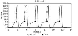
- FIG. 12 is a diagram showing time-series data of sensor values and output sensor values when clicks are repeatedly performed from the pressing force of the first target value.
- FIG. 13 is a diagram showing time-series data of sensor values and output sensor values when clicks are repeatedly performed from the pressing force of the second target value.
- FIG. 14 is a diagram showing time-series data of sensor values and output sensor values when clicks are repeatedly performed with a pressing force of the third target value.
- FIG. 15 is a diagram showing time-series data of sensor values and output sensor values when clicks are repeatedly performed with a pressing force of the fourth target value.
- FIG. 16 is a diagram showing time-series data of sensor values and output sensor values when clicks are repeatedly performed from the pressing force of the second target value at twice the speed in the case shown in FIG. be.
- each figure is a schematic diagram and is not necessarily strictly illustrated. Therefore, for example, scales and the like do not necessarily match in each drawing. Moreover, in each figure, the same code
- FIG. 1 is a diagram showing the configuration of a detection system 2 and a schematic cross-section of a capacitance switch 1 according to this embodiment.
- the detection system 2 shown in FIG. 1 is a system that detects user's operation input to the capacitance switch 1 .
- the detection system 2 comprises a capacitive switch 1 and a detection device 100 .
- the capacitive switch 1 is an example of a capacitive sensor, and includes a capacitive value that changes according to user operation.
- a sensor value output from the capacitance switch 1 corresponds to the capacitance value of the capacitance switch 1 .
- the capacitive switch 1 is an input device that receives an operation input from a user, and has, for example, both functions of a tactile switch and a touch sensor. A specific configuration of the capacitance switch 1 will be described later.
- the detection device 100 detects user's operation input to the capacitance switch 1 based on the sensor value output from the capacitance switch 1 . For example, the user can press and click the capacitive switch 1 .
- the detection device 100 calculates the amount of pressing by the pressing operation and determines whether or not there is a clicking operation, based on the sensor value.
- the detection device 100 is, for example, a microcontroller.
- the microcontroller includes a nonvolatile memory storing programs, a volatile memory that is a temporary storage area for executing programs, an input/output port, a processor executing programs, and the like. At least part of the functions performed by the detection device 100 may be implemented in software or hardware.
- the detection system 2 is used by the user to operate the camera.
- the amount of depression of the capacitance switch 1 is associated with the focus adjustment function of the camera.
- a click operation on the capacitance switch 1 is associated with a camera shutter function (that is, a shooting operation).
- the user can perform an operation of adjusting the amount of pressing and focusing on the subject for photographing.
- the application example of the detection system 2 is not limited to cameras.
- the detection system 2 can be applied to a wide variety of devices such as game machine controllers, touch panel displays, various display devices, and various operation terminals.
- the capacitance switch 1 includes a mounting base 10, a cover film 20, a push plate 30, a movable contact 40, movable electrodes 51 and 52, conductive rubbers 61 and 62, and an insulating sheet. 71 and 72 , fixed electrodes 81 and 82 , and conducting contacts 91 and 92 .
- the mounting base 10 is the main housing of the capacitance switch 1, and is configured in the shape of a tray with a recessed center.
- a cover film 20 is fixed to the mount 10 so as to cover the central recess.
- a push plate 30 is arranged on the lower surface of the center of the cover film 20 .
- bottom and top refer to directions determined by the positional relationship between the cover film 20 and the mount 10 , and the direction in which the mount 10 is positioned relative to the cover film 20 is defined as “bottom”. (downward)” and the opposite direction is “up (upper)”. That is, depending on the attitude of the capacitive switch 1 during actual use, the “bottom (lower side)” may not be vertically downward.
- the lower surface of the push plate 30 is in contact with the movable contact 40.
- the push plate 30 can push the movable contact 40 downward according to the pressing force from the user.
- the movable contact 40 is also called a metal dome and has a shape protruding upward.
- Movable electrodes 51 and 52 are connected to both ends of the movable contact 40 .
- the movable electrode 51 faces the fixed electrode 81 with the conductive rubber 61 and the insulating sheet 71 interposed therebetween.
- the movable electrode 51 and the fixed electrode 81 constitute a first capacitor Ca (see FIG. 4).
- the movable electrode 52 faces the fixed electrode 82 with the conductive rubber 62 and the insulating sheet 72 interposed therebetween.
- the movable electrode 52 and the fixed electrode 82 constitute a second capacitor Cb (see FIG. 4).
- the fixed electrodes 81 and 82 and the conductive contacts 91 and 92 are fixed to the mount 10.
- the fixed electrode 81 is connected to the detection device 100 as shown in FIG. Note that the detection device 100 may be arranged inside the mounting base 10 or may be attached to the outer surface of the mounting base 10 .
- Both the fixed electrode 82 and the conducting contact 92 are grounded (that is, grounded).
- the conducting contact 91 is open.
- the configuration of the capacitance switch 1 is not limited to the example shown in FIG.
- the capacitive switch 1 may not include the cover film 20 and may not include the conducting contacts 91 .
- FIG. 1 The user can operate the capacitance switch 1 by touching the upper surface of the cover film 20 and pressing the push plate 30 .
- Mechanical state transitions of the capacitive switch 1 when operated by a user will be described below with reference to FIGS. 2 and 3.
- FIG. 1
- FIG. 2 is a schematic cross-sectional view of the capacitance switch 1 when pushed.
- FIG. 3 is a schematic cross-sectional view of the capacitive switch 1 when clicked. It should be noted that FIG. 1 shows the capacitive switch 1 in a no-load state, that is, it is not pressed by a user.
- the cover film 20 is deformed and the push plate 30 moves downward due to the pressing force applied from above.
- the movable contact 40 and the movable electrodes 51 and 52 also move downward.
- the conductive rubbers 61 and 62 have flexibility, the conductive rubbers 61 and 62 are deformed by the downward moving force of the movable electrodes 51 and 52 .
- the distance between each of the movable electrodes 51 and 52 and the fixed electrodes 81 and 82 changes.
- a plurality of protrusions are provided on the lower surface of each of the conductive rubbers 61 and 62, and the protrusions are easily deformed to a large extent, so that the change in distance can be increased.
- the movable contact 40 is reversed as shown in FIG.
- the inverted movable contact 40 contacts conducting contacts 91 and 92 .
- the click operation is to press the movable contact 40 and the conducting contacts 91 and 92 until they come into contact with each other.
- the sensor value output by the capacitance switch 1 differs greatly between the pressing operation and the clicking operation.
- the output sensor value will be described below together with the equivalent circuit of the capacitance switch 1 .
- FIG. 4 is an equivalent circuit diagram of the capacitive switch 1 when pushed.
- the capacitance switch 1 includes a first capacitance Ca including the movable electrode 51 and the fixed electrode 81, and a second capacitance Cb including the movable electrode 52 and the fixed electrode 82.
- Both the first capacitor Ca and the second capacitor Cb are variable capacitors whose capacitance values change as the inter-electrode distance changes.
- the movable electrodes 51 and 52 are electrically connected via the movable contact 40 . Therefore, a series connection of the first capacitor Ca and the second capacitor Cb is formed between the fixed electrode 81 and the fixed electrode 82 .
- the sensor value C output to the detection device 100 corresponds to the capacitance value between the fixed electrode 81 and the ground, that is, the capacitance value of the series connection of the first capacitance Ca and the second capacitance Cb. Therefore, the sensor value C is represented by CA * CB /( CA + CB ). Note that the capacitance value CA is the capacitance value of the first capacitor Ca. The capacitance value CB is the capacitance value of the second capacitor Cb.
- FIG. 5 is an equivalent circuit diagram of the capacitive switch 1 when clicked.
- the movable contact 40 is brought into contact with the conducting contact 92, so that the movable contact 40 is grounded. Therefore, since both ends of the second capacitor Cb are connected to the ground, the capacitance value between the fixed electrode 81 and the ground is only the capacitance value CA of the first capacitor Ca. Therefore, before and after the click, the sensor value C changes greatly from CA ⁇ CB /( CA + CB ) to CA.
- FIG. 6 is a graph showing the relationship between the user's pressing force and the sensor value output by the capacitance switch 1.
- the distance between the electrodes decreases due to the deformation of the conductive rubbers 61 and 62 in both the first capacitor Ca and the second capacitor Cb. capacitance value) increases.
- the sensor value is kept substantially constant after the conductive rubbers 61 and 62 are sufficiently deformed.
- the movable contact 40 is reversed and comes into contact with the conductive contact 92, thereby greatly changing the capacitance value from CA ⁇ CB /( CA + CB ) to CA. Therefore, a click operation can be easily detected by setting a threshold between CA ⁇ CB /( CA + CB ) and CA.
- the conducting contact 91 conducts with the conducting contact 92 when clicked, and is connected to the ground. Therefore, the presence or absence of a click may be determined by detecting the potential of the conductive contact 91 .
- FIG. 7 is a block diagram showing the functional configuration of the detection device 100 according to this embodiment.
- the detection device 100 includes an acquisition unit 110, a determination unit 120, a first calculation unit 130, a second calculation unit 140, a comparison unit 150, an output unit 160, and a storage unit 170. , provided.
- the acquisition unit 110 periodically and repeatedly acquires the sensor value CX output from the capacitance switch 1 .
- the acquisition unit 110 causes the storage unit 170 to store the acquired sensor value CX as time-series sensor data 171 .
- X is a subscript representing the order in which the sensor values C are obtained.
- the sensor value C1 represents the latest sensor value. The larger the value of X, the past sensor value.
- the determination unit 120 determines whether or not the sensor value CX acquired by the acquisition unit 110 exceeds the threshold Th1.
- the threshold Th1 is an example of a first threshold, and is set between CA ⁇ CB /( CA + CB ) and CA , for example.
- the first calculation unit 130 sets the sensor value determined to exceed the threshold Th1 and a plurality of past sensor values in order from the sensor value as the target sensor value CX , and the target sensor value CX and the target sensor value A difference between CX and the immediately preceding sensor value CX +1 is calculated as a first difference value ⁇ 1X of the target sensor value CX .
- the first calculation unit 130 causes the storage unit 170 to store the first difference value ⁇ 1 X for each target sensor value C X as the first difference value data 172 . A specific process for calculating the first difference value ⁇ 1X will be described later.
- the second calculation unit 140 sets the sensor value determined to exceed the threshold Th1 and each of the plurality of past sensor values in order from the sensor value as the target sensor value CX , and the first difference of the target sensor value CX The difference between the value ⁇ 1X and the first difference value ⁇ 1X +1 of the sensor value CX+1 immediately before the target sensor value CX is calculated as the second difference value ⁇ 2X of the target sensor value CX .
- the second calculation unit 140 causes the storage unit 170 to store the second difference value ⁇ 2 X for each target sensor value C X as the second difference value data 173 . A specific process for calculating the second difference value ⁇ 2X will be described later.
- the comparison unit 150 compares the calculated second difference value ⁇ 2X with the threshold value Th2.
- the threshold Th2 is an example of a second threshold.
- the comparison unit 150 selects one sensor value C Ret from the sensor data 171 based on the comparison result.
- the sensor value C Ret selected by the comparison unit 150 is a value representing the pressing amount immediately before the click operation is performed. Specific selection processing will be described later.
- the output unit 160 outputs the sensor value C Ret selected by the comparison unit 150 . Moreover, the output unit 160 further outputs the result of determination by the determination unit 120 . Specifically, the output unit 160 outputs a signal indicating that a click operation has been performed as a determination result, and outputs a sensor value corresponding to the pressing amount immediately before the click operation is performed.
- the storage unit 170 is a memory for storing sensor data 171 .
- the storage unit 170 further stores first difference value data 172 and second difference value data 173 .
- the storage unit 170 is a memory capable of storing M (M is a natural number of 3 or more) sensor values C X , M ⁇ 1 first difference values ⁇ 1 X , and M ⁇ 2 second difference values ⁇ 2 X have capacity.
- the storage unit 170 stores programs executed by each processing unit of the detection device 100, and the like.
- the storage unit 170 may not be provided in the detection device 100 .
- the detecting device 100 may use a storage unit provided in a device capable of communicating with the detecting device 100 as the storage unit 170 .
- FIG. 8 is a flowchart showing the detection method according to this embodiment. The detection method shown in FIG. 8 is performed by the detection device 100 .
- the detecting device 100 updates the storage unit 170 (S11). Specifically, the detection device 100 secures a memory area for storing the latest sensor value C output from the capacitance switch 1 as the sensor value C1. More specifically, the detecting device 100 updates C 1 to C M ⁇ 1 among the sensor values C 1 to C M stored in the M memory areas to the sensor values C 2 to C M . Note that the oldest sensor value CM before update is deleted.
- the acquisition unit 110 acquires the sensor value C output from the capacitance switch 1 and stores it in the storage unit 170 as the sensor value C1 (S12).
- the determination unit 120 determines whether or not the acquired sensor value C1 exceeds the threshold Th1 (S13). If the sensor value C1 does not exceed the threshold Th1 (No in S13), the detection device 100 updates the memory again (S11). The sensor values are stored as sensor data 171 in the storage unit 170 until the sensor value C1 exceeds the threshold Th1.
- FIG. 9 is a diagram showing an example of sensor data 171 stored in the storage unit 170. As shown in FIG. FIG. 9 shows four graphs, each corresponding to one sensor data 171 . It should be noted that the four graphs show changes over time in sensor values when the user clicks after pressing four different target values.
- the plot of each graph is the sensor value output from the capacitance switch 1, that is, the sensor value acquired by the acquisition unit 110.
- sensor values are repeatedly output with a period of 33 ms.
- the threshold value Th1 is set to 1000, and the sensor value located in the vicinity of about 1.0 seconds is the latest sensor value C1 exceeding the threshold value Th1.
- the first calculator 130 calculates the target sensor value C As X , a first difference value ⁇ 1 X is calculated (S14).
- FIG. 10 is a diagram for explaining the process of calculating the first difference value ⁇ 1X and the second difference value ⁇ 2X .
- the first calculator 130 calculates the following equation (1) with each of the M ⁇ 1 sensor values C 1 to C M ⁇ 1 as the target sensor value C X . is used to calculate the first difference value ⁇ 1X .
- the calculated first difference value ⁇ 1 X is stored in storage unit 170 as first difference value data 172 .
- the second calculation unit 140 calculates a second difference value ⁇ 2X using the multiple sensor values stored in the storage unit 170 as the target sensor values CX (S15). Specifically, the second calculation unit 140 uses each of the M ⁇ 2 sensor values C 1 to C M ⁇ 2 as the target sensor value C X and calculates the second difference value ⁇ 2 using the following equation (2). Calculate X.
- the calculated second difference value ⁇ 2 X is stored in the storage unit 170 as the second difference value data 173 .
- FIG. 11 is a diagram for explaining the process of selecting the sensor value CRet to be output.
- two of the second difference values ⁇ 2 1 and ⁇ 2 2 exceed the threshold Th2.
- the comparison unit 150 determines the suffix Xmax of the second difference value ⁇ 2-2 corresponding to the oldest sensor value among the two second difference values ⁇ 2-1 and ⁇ 2-2 exceeding the threshold Th2.
- the output unit 160 outputs the determination result (click ON signal) indicating that a click operation has been performed, and the selected sensor value C Ret (S18). .
- [Effects, etc.] 12 to 15 show the results of verification of the detection accuracy by the detection method according to the present embodiment by the user actually performing a click operation at a frequency of once every two seconds.
- 12 to 15 are diagrams showing time-series data of sensor values and output sensor values when clicks are repeatedly performed with pressing forces of four different target values.
- the output sensor value C Ret is represented by square plots. As shown in the plots of C Ret in each figure, it can be seen that detection can be performed with roughly the target amount of depression regardless of the strength of the amount of depression immediately before clicking.
- FIG. 16 shows the case where the user's click operation is performed at twice the speed (once per second).
- FIG. 16 is a diagram showing time-series data of sensor values and output sensor values when clicking is repeatedly performed at twice the speed shown in FIG. 13 .
- FIG. 16 also shows a case where the sensor value C Ret ( ⁇ 1) is selected based on the comparison result between the first difference value ⁇ 1 X and the threshold without calculating the second difference value ⁇ 2 X.
- the method for selecting the sensor value C Ret ( ⁇ 1) is the same as the method for selecting the sensor value C Ret ( ⁇ 2 ) except that the first difference value ⁇ 1X is used instead of the second difference value ⁇ 2X.
- the threshold used for comparison a value suitable for comparison of the first difference value ⁇ 1X is used.
- the comparison result of the second difference value ⁇ 2X when used, the number of times a value close to the target value is detected is greater than when the comparison result of the first difference value ⁇ 1X is used. That is, according to the detection method according to the present embodiment, it can be seen that the detection accuracy of the sensor value immediately before the click operation is high.
- the detection method periodically and repeatedly acquires sensor values output from the capacitance switch 1, and uses the acquired sensor values as the time-series sensor data 171 in the storage unit 170.
- a determination step of determining whether the acquired sensor value exceeds the threshold Th1, a sensor value determined to exceed the threshold Th1, and a plurality of sensors in the past in order from the sensor value values are the target sensor values CX , and the difference between the target sensor value CX and the sensor value CX+1 immediately before the target sensor value CX is calculated as the first difference value ⁇ 1X of the target sensor value CX.
- the sensor value immediately before the click operation can be output with high accuracy. Since not only the presence or absence of the click operation but also the sensor value immediately before the click operation is output, application to various devices becomes possible and versatility is enhanced. The precision of the output sensor value is also good, so it can be applied to delicate operation inputs.
- the sensor value CX +1 immediately before the target sensor value CX corresponding to the second difference value ⁇ 2X exceeding the threshold Th2 is selected based on the comparison result.
- the comparison step when there are a plurality of second difference values ⁇ 2X exceeding the threshold Th2 based on the comparison result, the target sensor value CX corresponding to each of the plurality of second difference values ⁇ 2X Among them, the sensor value C Xmax+1 immediately before the most past sensor value C Xmax is selected.
- the determination result of the determination step is further output.
- the detecting device 100 periodically and repeatedly acquires the sensor values output from the capacitance switch 1, and stores the acquired sensor values in the storage unit 170 as time-series sensor data 171.
- the calculation unit 130 the sensor value determined to exceed the threshold Th1, and each of the plurality of past sensor values in order from the sensor value as the target sensor value CX , the first difference value ⁇ 1 of the target sensor value CX a second calculator 140 that calculates a difference between X and a first difference value ⁇ 1X +1 of the sensor value CX+ 1 immediately before the target sensor value CX as a second difference value ⁇ 2X of the target sensor value CX;
- a comparison unit 150 that compares the calculated second difference value ⁇ 2 X with the threshold value Th2 , selects one sensor value C Ret from the sensor data 171 based on the comparison result, and outputs the selected sensor value C Ret . and an output unit 160 that performs the processing.
- the detection system 2 includes the detection device 100 and the capacitance switch 1 .
- the first difference value ⁇ 1 X and the second difference value ⁇ 2 X are calculated when the sensor value C1 exceeds the threshold Th1, but the present invention is not limited to this.
- the first difference value ⁇ 1 X and the second difference value ⁇ 2 X may be obtained each time a sensor value is obtained.
- the sensor value C Ret selected by the comparison unit 150 may not be the sensor value C Xmax+1 . That is, the comparison unit 150 selects the sensor value from the most past sensor value, not the sensor value immediately before the most past sensor value, among the target sensor values corresponding to each of the plurality of second difference values exceeding the threshold Th2. A previous sensor value may be selected.
- the comparison unit 150 may output the sensor value C Xmax+2 , the sensor value C Xmax+3 , or the like as the sensor value C Ret .
- the sensor value C Xmax+1 and the sensor value C Xmax+2 or C Xmax+3 may become almost the same value. Therefore, even if the sensor value C Xmax+2 or C Xmax+3 is selected and output instead of the sensor value C Xmax+ 1 , it can be treated with substantially the same accuracy as the sensor value immediately before the click operation.
- the output unit 160 does not have to output a determination result indicating that a click operation has been performed.
- the device that receives the input of the sensor value C Ret may determine that the click operation has been performed when the sensor value C Ret is output and acquired.
- the processing executed by a specific processing unit may be executed by another processing unit.
- the order of multiple processes may be changed, or multiple processes may be executed in parallel.
- the distribution of the constituent elements of the detection system 2 to a plurality of devices is an example.
- a component included in one device may be included in another device.
- the detection system 2 may also be implemented as a single device.
- processing described in the above embodiments may be implemented by centralized processing using a single device (system), or may be implemented by distributed processing using a plurality of devices. good.
- the number of processors executing the above program may be singular or plural. That is, centralized processing may be performed, or distributed processing may be performed.
- all or part of the components such as the control unit may be configured with dedicated hardware, or implemented by executing a software program suitable for each component. good too.
- Each component may be implemented by a program execution unit such as a CPU (Central Processing Unit) or processor reading and executing a software program recorded in a recording medium such as a HDD (Hard Disk Drive) or semiconductor memory. good.
- a program execution unit such as a CPU (Central Processing Unit) or processor reading and executing a software program recorded in a recording medium such as a HDD (Hard Disk Drive) or semiconductor memory. good.
- components such as the control unit may be configured with one or more electronic circuits.
- Each of the one or more electronic circuits may be a general-purpose circuit or a dedicated circuit.
- One or more electronic circuits may include, for example, a semiconductor device, an IC (Integrated Circuit), or an LSI (Large Scale Integration).
- An IC or LSI may be integrated on one chip or may be integrated on a plurality of chips. Although they are called ICs or LSIs here, they may be called system LSIs, VLSIs (Very Large Scale Integration), or ULSIs (Ultra Large Scale Integration) depending on the degree of integration.
- An FPGA Field Programmable Gate Array
- general or specific aspects of the present disclosure may be implemented as a system, apparatus, method, integrated circuit, or computer program.
- the computer program may be implemented by a computer-readable non-temporary recording medium such as an optical disc, HDD, or semiconductor memory.
- any combination of systems, devices, methods, integrated circuits, computer programs and recording media may be implemented.
- the present disclosure can be used as a highly versatile detection method, detection device, detection system, and the like, and can be used, for example, for various input devices and user interface devices.
- Capacitance switch 2 Detection system 10 Mounting base 20 Cover film 30 Push plate 40 Movable contacts 51, 52 Movable electrodes 61, 62 Conductive rubbers 71, 72 Insulating sheets 81, 82 Fixed electrodes 91, 92 Conductive contacts 100 Detecting device 110 Acquisition Unit 120 Judgment unit 130 First calculation unit 140 Second calculation unit 150 Comparison unit 160 Output unit 170 Storage unit 171 Sensor data 172 First difference value data 173 Second difference value data Ca First capacitance Cb Second capacitance
Landscapes
- Engineering & Computer Science (AREA)
- Multimedia (AREA)
- Signal Processing (AREA)
- Physics & Mathematics (AREA)
- General Physics & Mathematics (AREA)
- General Engineering & Computer Science (AREA)
- Theoretical Computer Science (AREA)
- Human Computer Interaction (AREA)
- Switches That Are Operated By Magnetic Or Electric Fields (AREA)
- Geophysics And Detection Of Objects (AREA)
- Electronic Switches (AREA)
Priority Applications (3)
| Application Number | Priority Date | Filing Date | Title |
|---|---|---|---|
| CN202280046967.6A CN117597658A (zh) | 2021-08-03 | 2022-07-21 | 检测方法、检测装置以及检测系统 |
| JP2023540249A JPWO2023013430A1 (https=) | 2021-08-03 | 2022-07-21 | |
| US18/579,835 US12267068B2 (en) | 2021-08-03 | 2022-07-21 | Detection method, detection device, and detection system |
Applications Claiming Priority (2)
| Application Number | Priority Date | Filing Date | Title |
|---|---|---|---|
| JP2021-127758 | 2021-08-03 | ||
| JP2021127758 | 2021-08-03 |
Publications (1)
| Publication Number | Publication Date |
|---|---|
| WO2023013430A1 true WO2023013430A1 (ja) | 2023-02-09 |
Family
ID=85155581
Family Applications (1)
| Application Number | Title | Priority Date | Filing Date |
|---|---|---|---|
| PCT/JP2022/028347 Ceased WO2023013430A1 (ja) | 2021-08-03 | 2022-07-21 | 検出方法、検出装置及び検出システム |
Country Status (4)
| Country | Link |
|---|---|
| US (1) | US12267068B2 (https=) |
| JP (1) | JPWO2023013430A1 (https=) |
| CN (1) | CN117597658A (https=) |
| WO (1) | WO2023013430A1 (https=) |
Cited By (1)
| Publication number | Priority date | Publication date | Assignee | Title |
|---|---|---|---|---|
| EP4580062A1 (en) * | 2023-12-25 | 2025-07-02 | Toyo Denso Kabushiki Kaisha | Operating device |
Families Citing this family (2)
| Publication number | Priority date | Publication date | Assignee | Title |
|---|---|---|---|---|
| JP2025008187A (ja) * | 2023-07-04 | 2025-01-20 | キヤノン株式会社 | 電子機器 |
| TWI875580B (zh) * | 2024-04-29 | 2025-03-01 | 矽統科技股份有限公司 | 觸控板與鍵盤整合裝置 |
Citations (5)
| Publication number | Priority date | Publication date | Assignee | Title |
|---|---|---|---|---|
| JP2009239393A (ja) * | 2008-03-26 | 2009-10-15 | Fujikura Ltd | 機器制御装置 |
| WO2013187397A1 (ja) * | 2012-06-12 | 2013-12-19 | 株式会社フジクラ | 入力装置 |
| JP2014086837A (ja) * | 2012-10-23 | 2014-05-12 | Omron Corp | 光電センサ |
| JP2016115401A (ja) * | 2014-12-10 | 2016-06-23 | 株式会社朝日ラバー | クリック感付与感圧センサ |
| WO2020090535A1 (ja) * | 2018-11-02 | 2020-05-07 | パナソニックIpマネジメント株式会社 | 入力装置、及び入力システム |
Family Cites Families (14)
| Publication number | Priority date | Publication date | Assignee | Title |
|---|---|---|---|---|
| US9454270B2 (en) * | 2008-09-19 | 2016-09-27 | Apple Inc. | Systems and methods for detecting a press on a touch-sensitive surface |
| JP2011197750A (ja) | 2010-03-17 | 2011-10-06 | Nikon Corp | 入力装置 |
| US20110285662A1 (en) * | 2010-05-19 | 2011-11-24 | Nokia Corporation | Apparatus and method for an actuator in an electronic device |
| WO2012138404A2 (en) * | 2011-04-07 | 2012-10-11 | Cleankeys Inc. | Systems and methods for detecting a press on a touch-sensitive surface |
| US9104260B2 (en) * | 2012-04-10 | 2015-08-11 | Typesoft Technologies, Inc. | Systems and methods for detecting a press on a touch-sensitive surface |
| TWI463388B (zh) * | 2012-06-20 | 2014-12-01 | Orise Technology Co Ltd | 增進電容式多點觸控系統的觸碰座標計算準確度之方法及電容式多點觸控系統 |
| US20150185909A1 (en) * | 2012-07-06 | 2015-07-02 | Freescale Semiconductor, Inc. | Method of sensing a user input to a capacitive touch sensor, a capacitive touch sensor controller, an input device and an apparatus |
| JP5852050B2 (ja) * | 2013-05-27 | 2016-02-03 | 株式会社ジャパンディスプレイ | タッチ検出装置、タッチ検出機能付き表示装置、及び電子機器 |
| JP2015190859A (ja) * | 2014-03-28 | 2015-11-02 | ソニー株式会社 | センサ装置、入力装置及び電子機器 |
| TWI531949B (zh) * | 2014-06-26 | 2016-05-01 | 矽創電子股份有限公司 | 電容電壓資訊感測電路及其相關抗雜訊觸控電路 |
| US9626054B2 (en) * | 2014-12-19 | 2017-04-18 | Salt International Corp. | Capacitive sensing device and method that reduces influence from transient environmental changes |
| US10747358B2 (en) * | 2018-02-22 | 2020-08-18 | Wacom Co., Ltd. | Position detection circuit and position detection method |
| CN214956522U (zh) | 2018-06-01 | 2021-11-30 | 松下知识产权经营株式会社 | 输入装置 |
| US11909389B2 (en) | 2019-07-17 | 2024-02-20 | Panasonic Intellectual Property Management Co., Ltd. | Input device and input system |
-
2022
- 2022-07-21 WO PCT/JP2022/028347 patent/WO2023013430A1/ja not_active Ceased
- 2022-07-21 US US18/579,835 patent/US12267068B2/en active Active
- 2022-07-21 CN CN202280046967.6A patent/CN117597658A/zh active Pending
- 2022-07-21 JP JP2023540249A patent/JPWO2023013430A1/ja active Pending
Patent Citations (5)
| Publication number | Priority date | Publication date | Assignee | Title |
|---|---|---|---|---|
| JP2009239393A (ja) * | 2008-03-26 | 2009-10-15 | Fujikura Ltd | 機器制御装置 |
| WO2013187397A1 (ja) * | 2012-06-12 | 2013-12-19 | 株式会社フジクラ | 入力装置 |
| JP2014086837A (ja) * | 2012-10-23 | 2014-05-12 | Omron Corp | 光電センサ |
| JP2016115401A (ja) * | 2014-12-10 | 2016-06-23 | 株式会社朝日ラバー | クリック感付与感圧センサ |
| WO2020090535A1 (ja) * | 2018-11-02 | 2020-05-07 | パナソニックIpマネジメント株式会社 | 入力装置、及び入力システム |
Cited By (1)
| Publication number | Priority date | Publication date | Assignee | Title |
|---|---|---|---|---|
| EP4580062A1 (en) * | 2023-12-25 | 2025-07-02 | Toyo Denso Kabushiki Kaisha | Operating device |
Also Published As
| Publication number | Publication date |
|---|---|
| US12267068B2 (en) | 2025-04-01 |
| JPWO2023013430A1 (https=) | 2023-02-09 |
| US20240322824A1 (en) | 2024-09-26 |
| CN117597658A (zh) | 2024-02-23 |
Similar Documents
| Publication | Publication Date | Title |
|---|---|---|
| WO2023013430A1 (ja) | 検出方法、検出装置及び検出システム | |
| KR102708452B1 (ko) | 압력 신호 처리 | |
| US10082906B2 (en) | Touch detection circuit | |
| US8482536B1 (en) | Compensation of signal values for a touch sensor | |
| US20100302177A1 (en) | Method and apparatus for providing user interface based on contact position and intensity of contact force on touch screen | |
| US20170242539A1 (en) | Use based force auto-calibration | |
| EP3765166B1 (en) | Handheld controllers with touch-sensitive controls | |
| US20110080366A1 (en) | Resolution and sensitivity balance metric | |
| CN103885629B (zh) | 触摸传感器装置、电子设备、位置计算方法及位置计算程序 | |
| JP6224200B2 (ja) | 圧力検知信号を処理するための方法及びシステム | |
| JP7357298B2 (ja) | 入力装置、及び入力システム | |
| WO2013126094A1 (en) | Close touch detection and tracking | |
| US9489083B2 (en) | Touch panel controller, touch sensor system, and electronic device | |
| CN103270478B (zh) | 在干扰环境中检测目标对象的方法和实施所述方法的手势界面设备 | |
| US9983752B2 (en) | Pressure detection method for in-cell touch display and mobile device using the same | |
| US10180751B2 (en) | Sensing device for force and tactile-proximity sensing | |
| KR101928318B1 (ko) | 압력 검출 방법 및 압력 검출 장치 | |
| US20110227823A1 (en) | Puck-type pointing apparatus, pointing system, and pointing method | |
| US11868577B2 (en) | Input check device having a pressing force threshold based on a detected minimum pressing force and input check method | |
| KR20170026269A (ko) | 입력 물체에 의해 터치 센서에 가해진 힘의 추정 | |
| JP7103782B2 (ja) | 入力装置および入力制御装置 | |
| CN107533414A (zh) | 用于力检测器的抖动滤波器 | |
| KR102943808B1 (ko) | 터치 모션을 식별하는 버튼 모듈 | |
| JPWO2015008705A1 (ja) | タッチパネルシステム及び電子情報機器 | |
| CN107949825B (zh) | 针对降落-抬起事件的位置过滤 |
Legal Events
| Date | Code | Title | Description |
|---|---|---|---|
| 121 | Ep: the epo has been informed by wipo that ep was designated in this application |
Ref document number: 22852854 Country of ref document: EP Kind code of ref document: A1 |
|
| WWE | Wipo information: entry into national phase |
Ref document number: 202280046967.6 Country of ref document: CN |
|
| WWE | Wipo information: entry into national phase |
Ref document number: 18579835 Country of ref document: US |
|
| WWE | Wipo information: entry into national phase |
Ref document number: 2023540249 Country of ref document: JP |
|
| NENP | Non-entry into the national phase |
Ref country code: DE |
|
| 122 | Ep: pct application non-entry in european phase |
Ref document number: 22852854 Country of ref document: EP Kind code of ref document: A1 |
|
| WWG | Wipo information: grant in national office |
Ref document number: 18579835 Country of ref document: US |