WO2023013430A1 - 検出方法、検出装置及び検出システム - Google Patents
検出方法、検出装置及び検出システム Download PDFInfo
- Publication number
- WO2023013430A1 WO2023013430A1 PCT/JP2022/028347 JP2022028347W WO2023013430A1 WO 2023013430 A1 WO2023013430 A1 WO 2023013430A1 JP 2022028347 W JP2022028347 W JP 2022028347W WO 2023013430 A1 WO2023013430 A1 WO 2023013430A1
- Authority
- WO
- WIPO (PCT)
- Prior art keywords
- value
- sensor
- sensor value
- difference
- target
- Prior art date
Links
- 238000001514 detection method Methods 0.000 title claims abstract description 75
- 238000004364 calculation method Methods 0.000 claims abstract description 23
- 238000003825 pressing Methods 0.000 description 24
- 238000010586 diagram Methods 0.000 description 22
- 239000003990 capacitor Substances 0.000 description 13
- 238000000034 method Methods 0.000 description 12
- 239000013039 cover film Substances 0.000 description 9
- 229920001971 elastomer Polymers 0.000 description 9
- 239000005060 rubber Substances 0.000 description 9
- 230000008569 process Effects 0.000 description 8
- 239000000470 constituent Substances 0.000 description 4
- 230000006870 function Effects 0.000 description 4
- 230000010354 integration Effects 0.000 description 4
- 238000004590 computer program Methods 0.000 description 3
- 239000004065 semiconductor Substances 0.000 description 3
- 230000008859 change Effects 0.000 description 2
- 230000000694 effects Effects 0.000 description 2
- 230000000052 comparative effect Effects 0.000 description 1
- 230000007423 decrease Effects 0.000 description 1
- 239000000463 material Substances 0.000 description 1
- 239000002184 metal Substances 0.000 description 1
- 238000012986 modification Methods 0.000 description 1
- 230000004048 modification Effects 0.000 description 1
- 230000003287 optical effect Effects 0.000 description 1
- 230000007704 transition Effects 0.000 description 1
- 238000012795 verification Methods 0.000 description 1
Images


Classifications
-
- G—PHYSICS
- G03—PHOTOGRAPHY; CINEMATOGRAPHY; ANALOGOUS TECHNIQUES USING WAVES OTHER THAN OPTICAL WAVES; ELECTROGRAPHY; HOLOGRAPHY
- G03B—APPARATUS OR ARRANGEMENTS FOR TAKING PHOTOGRAPHS OR FOR PROJECTING OR VIEWING THEM; APPARATUS OR ARRANGEMENTS EMPLOYING ANALOGOUS TECHNIQUES USING WAVES OTHER THAN OPTICAL WAVES; ACCESSORIES THEREFOR
- G03B17/00—Details of cameras or camera bodies; Accessories therefor
- G03B17/02—Bodies
-
- G—PHYSICS
- G06—COMPUTING; CALCULATING OR COUNTING
- G06F—ELECTRIC DIGITAL DATA PROCESSING
- G06F3/00—Input arrangements for transferring data to be processed into a form capable of being handled by the computer; Output arrangements for transferring data from processing unit to output unit, e.g. interface arrangements
- G06F3/01—Input arrangements or combined input and output arrangements for interaction between user and computer
- G06F3/02—Input arrangements using manually operated switches, e.g. using keyboards or dials
-
- H—ELECTRICITY
- H01—ELECTRIC ELEMENTS
- H01H—ELECTRIC SWITCHES; RELAYS; SELECTORS; EMERGENCY PROTECTIVE DEVICES
- H01H13/00—Switches having rectilinearly-movable operating part or parts adapted for pushing or pulling in one direction only, e.g. push-button switch
-
- H—ELECTRICITY
- H01—ELECTRIC ELEMENTS
- H01H—ELECTRIC SWITCHES; RELAYS; SELECTORS; EMERGENCY PROTECTIVE DEVICES
- H01H13/00—Switches having rectilinearly-movable operating part or parts adapted for pushing or pulling in one direction only, e.g. push-button switch
- H01H13/50—Switches having rectilinearly-movable operating part or parts adapted for pushing or pulling in one direction only, e.g. push-button switch having a single operating member
- H01H13/52—Switches having rectilinearly-movable operating part or parts adapted for pushing or pulling in one direction only, e.g. push-button switch having a single operating member the contact returning to its original state immediately upon removal of operating force, e.g. bell-push switch
-
- H—ELECTRICITY
- H03—ELECTRONIC CIRCUITRY
- H03K—PULSE TECHNIQUE
- H03K17/00—Electronic switching or gating, i.e. not by contact-making and –breaking
- H03K17/94—Electronic switching or gating, i.e. not by contact-making and –breaking characterised by the way in which the control signals are generated
- H03K17/945—Proximity switches
- H03K17/955—Proximity switches using a capacitive detector
Definitions
- the present disclosure relates to detection methods, detection devices, and detection systems.
- Patent Document 1 discloses an input device that outputs a video signal based on a pressing force detected by a pressure sensor.
- information to be displayed is switched when the detected pressing force exceeds a threshold.
- the above-described conventional input device can only perform control based on the binary value of whether or not the pressing force exceeds the threshold. For this reason, there is a problem that the mode of use is limited and versatility is low.
- the present disclosure provides a highly versatile detection method, detection device, and detection system.
- a detection method includes an acquisition step of periodically and repeatedly acquiring a sensor value output from a capacitance sensor, and storing the acquired sensor value in a memory as time-series sensor data; a determination step of determining whether or not the sensor value exceeds a first threshold; a sensor value determined to have exceeded the first threshold; As a first calculation step of calculating the difference between the target sensor value and the sensor value immediately before the target sensor value as the first difference value of the target sensor value, and the sensor value determined to exceed the first threshold, And, with each of a plurality of past sensor values in order from the sensor value as the target sensor value, the difference between the first difference value of the target sensor value and the first difference value of the sensor value immediately before the target sensor value, A second calculation step of calculating a second difference value of the target sensor value, a comparison of comparing the calculated second difference value with a second threshold, and selecting one sensor value from the sensor data based on the comparison result. and an output step of outputting the selected sensor value.
- a detection device includes an acquisition unit that periodically and repeatedly acquires a sensor value output from a capacitance sensor and stores the acquired sensor value in a memory as time-series sensor data; A determination unit that determines whether the sensor value exceeds a first threshold, a sensor value that is determined to have exceeded the first threshold, and a plurality of past sensor values in order from the sensor value as target sensor values As a first calculation unit that calculates the difference between the target sensor value and the sensor value immediately before the target sensor value as the first difference value of the target sensor value, and the sensor value determined to exceed the first threshold, And, with each of a plurality of past sensor values in order from the sensor value as the target sensor value, the difference between the first difference value of the target sensor value and the first difference value of the sensor value immediately before the target sensor value, A comparison that compares the calculated second difference value with a second threshold value and selects one sensor value from the sensor data based on the comparison result with a second calculation unit that calculates the second difference value of the target sensor value and an output
- a detection system includes the detection device according to the aspect described above and the capacitance sensor.
- FIG. 1 is a diagram showing the configuration of a detection system according to an embodiment and a schematic cross-section of a capacitive switch.
- FIG. 2 is a schematic cross-sectional view of the capacitive switch when pushed.
- FIG. 3 is a schematic cross-sectional view of a capacitive switch when clicked.
- FIG. 4 is an equivalent circuit diagram of a capacitive switch under no load or when pushed.
- FIG. 5 is an equivalent circuit diagram of the capacitive switch when clicked.
- FIG. 6 is a graph showing the relationship between the user's pressing force and the sensor value output by the capacitance switch.
- FIG. 7 is a block diagram showing the functional configuration of the detection device according to the embodiment.
- FIG. 8 is a flow chart showing the detection method according to the embodiment.
- FIG. 9 is a diagram showing an example of changes over time in sensor values when the capacitive switch is used.
- FIG. 10 is a diagram for explaining the process of calculating the first difference value and the second difference value.
- FIG. 11 is a diagram for explaining the process of selecting sensor values to be output.
- FIG. 12 is a diagram showing time-series data of sensor values and output sensor values when clicks are repeatedly performed from the pressing force of the first target value.
- FIG. 13 is a diagram showing time-series data of sensor values and output sensor values when clicks are repeatedly performed from the pressing force of the second target value.
- FIG. 14 is a diagram showing time-series data of sensor values and output sensor values when clicks are repeatedly performed with a pressing force of the third target value.
- FIG. 15 is a diagram showing time-series data of sensor values and output sensor values when clicks are repeatedly performed with a pressing force of the fourth target value.
- FIG. 16 is a diagram showing time-series data of sensor values and output sensor values when clicks are repeatedly performed from the pressing force of the second target value at twice the speed in the case shown in FIG. be.
- each figure is a schematic diagram and is not necessarily strictly illustrated. Therefore, for example, scales and the like do not necessarily match in each drawing. Moreover, in each figure, the same code
- FIG. 1 is a diagram showing the configuration of a detection system 2 and a schematic cross-section of a capacitance switch 1 according to this embodiment.
- the detection system 2 shown in FIG. 1 is a system that detects user's operation input to the capacitance switch 1 .
- the detection system 2 comprises a capacitive switch 1 and a detection device 100 .
- the capacitive switch 1 is an example of a capacitive sensor, and includes a capacitive value that changes according to user operation.
- a sensor value output from the capacitance switch 1 corresponds to the capacitance value of the capacitance switch 1 .
- the capacitive switch 1 is an input device that receives an operation input from a user, and has, for example, both functions of a tactile switch and a touch sensor. A specific configuration of the capacitance switch 1 will be described later.
- the detection device 100 detects user's operation input to the capacitance switch 1 based on the sensor value output from the capacitance switch 1 . For example, the user can press and click the capacitive switch 1 .
- the detection device 100 calculates the amount of pressing by the pressing operation and determines whether or not there is a clicking operation, based on the sensor value.
- the detection device 100 is, for example, a microcontroller.
- the microcontroller includes a nonvolatile memory storing programs, a volatile memory that is a temporary storage area for executing programs, an input/output port, a processor executing programs, and the like. At least part of the functions performed by the detection device 100 may be implemented in software or hardware.
- the detection system 2 is used by the user to operate the camera.
- the amount of depression of the capacitance switch 1 is associated with the focus adjustment function of the camera.
- a click operation on the capacitance switch 1 is associated with a camera shutter function (that is, a shooting operation).
- the user can perform an operation of adjusting the amount of pressing and focusing on the subject for photographing.
- the application example of the detection system 2 is not limited to cameras.
- the detection system 2 can be applied to a wide variety of devices such as game machine controllers, touch panel displays, various display devices, and various operation terminals.
- the capacitance switch 1 includes a mounting base 10, a cover film 20, a push plate 30, a movable contact 40, movable electrodes 51 and 52, conductive rubbers 61 and 62, and an insulating sheet. 71 and 72 , fixed electrodes 81 and 82 , and conducting contacts 91 and 92 .
- the mounting base 10 is the main housing of the capacitance switch 1, and is configured in the shape of a tray with a recessed center.
- a cover film 20 is fixed to the mount 10 so as to cover the central recess.
- a push plate 30 is arranged on the lower surface of the center of the cover film 20 .
- bottom and top refer to directions determined by the positional relationship between the cover film 20 and the mount 10 , and the direction in which the mount 10 is positioned relative to the cover film 20 is defined as “bottom”. (downward)” and the opposite direction is “up (upper)”. That is, depending on the attitude of the capacitive switch 1 during actual use, the “bottom (lower side)” may not be vertically downward.
- the lower surface of the push plate 30 is in contact with the movable contact 40.
- the push plate 30 can push the movable contact 40 downward according to the pressing force from the user.
- the movable contact 40 is also called a metal dome and has a shape protruding upward.
- Movable electrodes 51 and 52 are connected to both ends of the movable contact 40 .
- the movable electrode 51 faces the fixed electrode 81 with the conductive rubber 61 and the insulating sheet 71 interposed therebetween.
- the movable electrode 51 and the fixed electrode 81 constitute a first capacitor Ca (see FIG. 4).
- the movable electrode 52 faces the fixed electrode 82 with the conductive rubber 62 and the insulating sheet 72 interposed therebetween.
- the movable electrode 52 and the fixed electrode 82 constitute a second capacitor Cb (see FIG. 4).
- the fixed electrodes 81 and 82 and the conductive contacts 91 and 92 are fixed to the mount 10.
- the fixed electrode 81 is connected to the detection device 100 as shown in FIG. Note that the detection device 100 may be arranged inside the mounting base 10 or may be attached to the outer surface of the mounting base 10 .
- Both the fixed electrode 82 and the conducting contact 92 are grounded (that is, grounded).
- the conducting contact 91 is open.
- the configuration of the capacitance switch 1 is not limited to the example shown in FIG.
- the capacitive switch 1 may not include the cover film 20 and may not include the conducting contacts 91 .
- FIG. 1 The user can operate the capacitance switch 1 by touching the upper surface of the cover film 20 and pressing the push plate 30 .
- Mechanical state transitions of the capacitive switch 1 when operated by a user will be described below with reference to FIGS. 2 and 3.
- FIG. 1
- FIG. 2 is a schematic cross-sectional view of the capacitance switch 1 when pushed.
- FIG. 3 is a schematic cross-sectional view of the capacitive switch 1 when clicked. It should be noted that FIG. 1 shows the capacitive switch 1 in a no-load state, that is, it is not pressed by a user.
- the cover film 20 is deformed and the push plate 30 moves downward due to the pressing force applied from above.
- the movable contact 40 and the movable electrodes 51 and 52 also move downward.
- the conductive rubbers 61 and 62 have flexibility, the conductive rubbers 61 and 62 are deformed by the downward moving force of the movable electrodes 51 and 52 .
- the distance between each of the movable electrodes 51 and 52 and the fixed electrodes 81 and 82 changes.
- a plurality of protrusions are provided on the lower surface of each of the conductive rubbers 61 and 62, and the protrusions are easily deformed to a large extent, so that the change in distance can be increased.
- the movable contact 40 is reversed as shown in FIG.
- the inverted movable contact 40 contacts conducting contacts 91 and 92 .
- the click operation is to press the movable contact 40 and the conducting contacts 91 and 92 until they come into contact with each other.
- the sensor value output by the capacitance switch 1 differs greatly between the pressing operation and the clicking operation.
- the output sensor value will be described below together with the equivalent circuit of the capacitance switch 1 .
- FIG. 4 is an equivalent circuit diagram of the capacitive switch 1 when pushed.
- the capacitance switch 1 includes a first capacitance Ca including the movable electrode 51 and the fixed electrode 81, and a second capacitance Cb including the movable electrode 52 and the fixed electrode 82.
- Both the first capacitor Ca and the second capacitor Cb are variable capacitors whose capacitance values change as the inter-electrode distance changes.
- the movable electrodes 51 and 52 are electrically connected via the movable contact 40 . Therefore, a series connection of the first capacitor Ca and the second capacitor Cb is formed between the fixed electrode 81 and the fixed electrode 82 .
- the sensor value C output to the detection device 100 corresponds to the capacitance value between the fixed electrode 81 and the ground, that is, the capacitance value of the series connection of the first capacitance Ca and the second capacitance Cb. Therefore, the sensor value C is represented by CA * CB /( CA + CB ). Note that the capacitance value CA is the capacitance value of the first capacitor Ca. The capacitance value CB is the capacitance value of the second capacitor Cb.
- FIG. 5 is an equivalent circuit diagram of the capacitive switch 1 when clicked.
- the movable contact 40 is brought into contact with the conducting contact 92, so that the movable contact 40 is grounded. Therefore, since both ends of the second capacitor Cb are connected to the ground, the capacitance value between the fixed electrode 81 and the ground is only the capacitance value CA of the first capacitor Ca. Therefore, before and after the click, the sensor value C changes greatly from CA ⁇ CB /( CA + CB ) to CA.
- FIG. 6 is a graph showing the relationship between the user's pressing force and the sensor value output by the capacitance switch 1.
- the distance between the electrodes decreases due to the deformation of the conductive rubbers 61 and 62 in both the first capacitor Ca and the second capacitor Cb. capacitance value) increases.
- the sensor value is kept substantially constant after the conductive rubbers 61 and 62 are sufficiently deformed.
- the movable contact 40 is reversed and comes into contact with the conductive contact 92, thereby greatly changing the capacitance value from CA ⁇ CB /( CA + CB ) to CA. Therefore, a click operation can be easily detected by setting a threshold between CA ⁇ CB /( CA + CB ) and CA.
- the conducting contact 91 conducts with the conducting contact 92 when clicked, and is connected to the ground. Therefore, the presence or absence of a click may be determined by detecting the potential of the conductive contact 91 .
- FIG. 7 is a block diagram showing the functional configuration of the detection device 100 according to this embodiment.
- the detection device 100 includes an acquisition unit 110, a determination unit 120, a first calculation unit 130, a second calculation unit 140, a comparison unit 150, an output unit 160, and a storage unit 170. , provided.
- the acquisition unit 110 periodically and repeatedly acquires the sensor value CX output from the capacitance switch 1 .
- the acquisition unit 110 causes the storage unit 170 to store the acquired sensor value CX as time-series sensor data 171 .
- X is a subscript representing the order in which the sensor values C are obtained.
- the sensor value C1 represents the latest sensor value. The larger the value of X, the past sensor value.
- the determination unit 120 determines whether or not the sensor value CX acquired by the acquisition unit 110 exceeds the threshold Th1.
- the threshold Th1 is an example of a first threshold, and is set between CA ⁇ CB /( CA + CB ) and CA , for example.
- the first calculation unit 130 sets the sensor value determined to exceed the threshold Th1 and a plurality of past sensor values in order from the sensor value as the target sensor value CX , and the target sensor value CX and the target sensor value A difference between CX and the immediately preceding sensor value CX +1 is calculated as a first difference value ⁇ 1X of the target sensor value CX .
- the first calculation unit 130 causes the storage unit 170 to store the first difference value ⁇ 1 X for each target sensor value C X as the first difference value data 172 . A specific process for calculating the first difference value ⁇ 1X will be described later.
- the second calculation unit 140 sets the sensor value determined to exceed the threshold Th1 and each of the plurality of past sensor values in order from the sensor value as the target sensor value CX , and the first difference of the target sensor value CX The difference between the value ⁇ 1X and the first difference value ⁇ 1X +1 of the sensor value CX+1 immediately before the target sensor value CX is calculated as the second difference value ⁇ 2X of the target sensor value CX .
- the second calculation unit 140 causes the storage unit 170 to store the second difference value ⁇ 2 X for each target sensor value C X as the second difference value data 173 . A specific process for calculating the second difference value ⁇ 2X will be described later.
- the comparison unit 150 compares the calculated second difference value ⁇ 2X with the threshold value Th2.
- the threshold Th2 is an example of a second threshold.
- the comparison unit 150 selects one sensor value C Ret from the sensor data 171 based on the comparison result.
- the sensor value C Ret selected by the comparison unit 150 is a value representing the pressing amount immediately before the click operation is performed. Specific selection processing will be described later.
- the output unit 160 outputs the sensor value C Ret selected by the comparison unit 150 . Moreover, the output unit 160 further outputs the result of determination by the determination unit 120 . Specifically, the output unit 160 outputs a signal indicating that a click operation has been performed as a determination result, and outputs a sensor value corresponding to the pressing amount immediately before the click operation is performed.
- the storage unit 170 is a memory for storing sensor data 171 .
- the storage unit 170 further stores first difference value data 172 and second difference value data 173 .
- the storage unit 170 is a memory capable of storing M (M is a natural number of 3 or more) sensor values C X , M ⁇ 1 first difference values ⁇ 1 X , and M ⁇ 2 second difference values ⁇ 2 X have capacity.
- the storage unit 170 stores programs executed by each processing unit of the detection device 100, and the like.
- the storage unit 170 may not be provided in the detection device 100 .
- the detecting device 100 may use a storage unit provided in a device capable of communicating with the detecting device 100 as the storage unit 170 .
- FIG. 8 is a flowchart showing the detection method according to this embodiment. The detection method shown in FIG. 8 is performed by the detection device 100 .
- the detecting device 100 updates the storage unit 170 (S11). Specifically, the detection device 100 secures a memory area for storing the latest sensor value C output from the capacitance switch 1 as the sensor value C1. More specifically, the detecting device 100 updates C 1 to C M ⁇ 1 among the sensor values C 1 to C M stored in the M memory areas to the sensor values C 2 to C M . Note that the oldest sensor value CM before update is deleted.
- the acquisition unit 110 acquires the sensor value C output from the capacitance switch 1 and stores it in the storage unit 170 as the sensor value C1 (S12).
- the determination unit 120 determines whether or not the acquired sensor value C1 exceeds the threshold Th1 (S13). If the sensor value C1 does not exceed the threshold Th1 (No in S13), the detection device 100 updates the memory again (S11). The sensor values are stored as sensor data 171 in the storage unit 170 until the sensor value C1 exceeds the threshold Th1.
- FIG. 9 is a diagram showing an example of sensor data 171 stored in the storage unit 170. As shown in FIG. FIG. 9 shows four graphs, each corresponding to one sensor data 171 . It should be noted that the four graphs show changes over time in sensor values when the user clicks after pressing four different target values.
- the plot of each graph is the sensor value output from the capacitance switch 1, that is, the sensor value acquired by the acquisition unit 110.
- sensor values are repeatedly output with a period of 33 ms.
- the threshold value Th1 is set to 1000, and the sensor value located in the vicinity of about 1.0 seconds is the latest sensor value C1 exceeding the threshold value Th1.
- the first calculator 130 calculates the target sensor value C As X , a first difference value ⁇ 1 X is calculated (S14).
- FIG. 10 is a diagram for explaining the process of calculating the first difference value ⁇ 1X and the second difference value ⁇ 2X .
- the first calculator 130 calculates the following equation (1) with each of the M ⁇ 1 sensor values C 1 to C M ⁇ 1 as the target sensor value C X . is used to calculate the first difference value ⁇ 1X .
- the calculated first difference value ⁇ 1 X is stored in storage unit 170 as first difference value data 172 .
- the second calculation unit 140 calculates a second difference value ⁇ 2X using the multiple sensor values stored in the storage unit 170 as the target sensor values CX (S15). Specifically, the second calculation unit 140 uses each of the M ⁇ 2 sensor values C 1 to C M ⁇ 2 as the target sensor value C X and calculates the second difference value ⁇ 2 using the following equation (2). Calculate X.
- the calculated second difference value ⁇ 2 X is stored in the storage unit 170 as the second difference value data 173 .
- FIG. 11 is a diagram for explaining the process of selecting the sensor value CRet to be output.
- two of the second difference values ⁇ 2 1 and ⁇ 2 2 exceed the threshold Th2.
- the comparison unit 150 determines the suffix Xmax of the second difference value ⁇ 2-2 corresponding to the oldest sensor value among the two second difference values ⁇ 2-1 and ⁇ 2-2 exceeding the threshold Th2.
- the output unit 160 outputs the determination result (click ON signal) indicating that a click operation has been performed, and the selected sensor value C Ret (S18). .
- [Effects, etc.] 12 to 15 show the results of verification of the detection accuracy by the detection method according to the present embodiment by the user actually performing a click operation at a frequency of once every two seconds.
- 12 to 15 are diagrams showing time-series data of sensor values and output sensor values when clicks are repeatedly performed with pressing forces of four different target values.
- the output sensor value C Ret is represented by square plots. As shown in the plots of C Ret in each figure, it can be seen that detection can be performed with roughly the target amount of depression regardless of the strength of the amount of depression immediately before clicking.
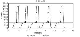
- FIG. 16 shows the case where the user's click operation is performed at twice the speed (once per second).
- FIG. 16 is a diagram showing time-series data of sensor values and output sensor values when clicking is repeatedly performed at twice the speed shown in FIG. 13 .
- FIG. 16 also shows a case where the sensor value C Ret ( ⁇ 1) is selected based on the comparison result between the first difference value ⁇ 1 X and the threshold without calculating the second difference value ⁇ 2 X.
- the method for selecting the sensor value C Ret ( ⁇ 1) is the same as the method for selecting the sensor value C Ret ( ⁇ 2 ) except that the first difference value ⁇ 1X is used instead of the second difference value ⁇ 2X.
- the threshold used for comparison a value suitable for comparison of the first difference value ⁇ 1X is used.
- the comparison result of the second difference value ⁇ 2X when used, the number of times a value close to the target value is detected is greater than when the comparison result of the first difference value ⁇ 1X is used. That is, according to the detection method according to the present embodiment, it can be seen that the detection accuracy of the sensor value immediately before the click operation is high.
- the detection method periodically and repeatedly acquires sensor values output from the capacitance switch 1, and uses the acquired sensor values as the time-series sensor data 171 in the storage unit 170.
- a determination step of determining whether the acquired sensor value exceeds the threshold Th1, a sensor value determined to exceed the threshold Th1, and a plurality of sensors in the past in order from the sensor value values are the target sensor values CX , and the difference between the target sensor value CX and the sensor value CX+1 immediately before the target sensor value CX is calculated as the first difference value ⁇ 1X of the target sensor value CX.
- the sensor value immediately before the click operation can be output with high accuracy. Since not only the presence or absence of the click operation but also the sensor value immediately before the click operation is output, application to various devices becomes possible and versatility is enhanced. The precision of the output sensor value is also good, so it can be applied to delicate operation inputs.
- the sensor value CX +1 immediately before the target sensor value CX corresponding to the second difference value ⁇ 2X exceeding the threshold Th2 is selected based on the comparison result.
- the comparison step when there are a plurality of second difference values ⁇ 2X exceeding the threshold Th2 based on the comparison result, the target sensor value CX corresponding to each of the plurality of second difference values ⁇ 2X Among them, the sensor value C Xmax+1 immediately before the most past sensor value C Xmax is selected.
- the determination result of the determination step is further output.
- the detecting device 100 periodically and repeatedly acquires the sensor values output from the capacitance switch 1, and stores the acquired sensor values in the storage unit 170 as time-series sensor data 171.
- the calculation unit 130 the sensor value determined to exceed the threshold Th1, and each of the plurality of past sensor values in order from the sensor value as the target sensor value CX , the first difference value ⁇ 1 of the target sensor value CX a second calculator 140 that calculates a difference between X and a first difference value ⁇ 1X +1 of the sensor value CX+ 1 immediately before the target sensor value CX as a second difference value ⁇ 2X of the target sensor value CX;
- a comparison unit 150 that compares the calculated second difference value ⁇ 2 X with the threshold value Th2 , selects one sensor value C Ret from the sensor data 171 based on the comparison result, and outputs the selected sensor value C Ret . and an output unit 160 that performs the processing.
- the detection system 2 includes the detection device 100 and the capacitance switch 1 .
- the first difference value ⁇ 1 X and the second difference value ⁇ 2 X are calculated when the sensor value C1 exceeds the threshold Th1, but the present invention is not limited to this.
- the first difference value ⁇ 1 X and the second difference value ⁇ 2 X may be obtained each time a sensor value is obtained.
- the sensor value C Ret selected by the comparison unit 150 may not be the sensor value C Xmax+1 . That is, the comparison unit 150 selects the sensor value from the most past sensor value, not the sensor value immediately before the most past sensor value, among the target sensor values corresponding to each of the plurality of second difference values exceeding the threshold Th2. A previous sensor value may be selected.
- the comparison unit 150 may output the sensor value C Xmax+2 , the sensor value C Xmax+3 , or the like as the sensor value C Ret .
- the sensor value C Xmax+1 and the sensor value C Xmax+2 or C Xmax+3 may become almost the same value. Therefore, even if the sensor value C Xmax+2 or C Xmax+3 is selected and output instead of the sensor value C Xmax+ 1 , it can be treated with substantially the same accuracy as the sensor value immediately before the click operation.
- the output unit 160 does not have to output a determination result indicating that a click operation has been performed.
- the device that receives the input of the sensor value C Ret may determine that the click operation has been performed when the sensor value C Ret is output and acquired.
- the processing executed by a specific processing unit may be executed by another processing unit.
- the order of multiple processes may be changed, or multiple processes may be executed in parallel.
- the distribution of the constituent elements of the detection system 2 to a plurality of devices is an example.
- a component included in one device may be included in another device.
- the detection system 2 may also be implemented as a single device.
- processing described in the above embodiments may be implemented by centralized processing using a single device (system), or may be implemented by distributed processing using a plurality of devices. good.
- the number of processors executing the above program may be singular or plural. That is, centralized processing may be performed, or distributed processing may be performed.
- all or part of the components such as the control unit may be configured with dedicated hardware, or implemented by executing a software program suitable for each component. good too.
- Each component may be implemented by a program execution unit such as a CPU (Central Processing Unit) or processor reading and executing a software program recorded in a recording medium such as a HDD (Hard Disk Drive) or semiconductor memory. good.
- a program execution unit such as a CPU (Central Processing Unit) or processor reading and executing a software program recorded in a recording medium such as a HDD (Hard Disk Drive) or semiconductor memory. good.
- components such as the control unit may be configured with one or more electronic circuits.
- Each of the one or more electronic circuits may be a general-purpose circuit or a dedicated circuit.
- One or more electronic circuits may include, for example, a semiconductor device, an IC (Integrated Circuit), or an LSI (Large Scale Integration).
- An IC or LSI may be integrated on one chip or may be integrated on a plurality of chips. Although they are called ICs or LSIs here, they may be called system LSIs, VLSIs (Very Large Scale Integration), or ULSIs (Ultra Large Scale Integration) depending on the degree of integration.
- An FPGA Field Programmable Gate Array
- general or specific aspects of the present disclosure may be implemented as a system, apparatus, method, integrated circuit, or computer program.
- the computer program may be implemented by a computer-readable non-temporary recording medium such as an optical disc, HDD, or semiconductor memory.
- any combination of systems, devices, methods, integrated circuits, computer programs and recording media may be implemented.
- the present disclosure can be used as a highly versatile detection method, detection device, detection system, and the like, and can be used, for example, for various input devices and user interface devices.
- Capacitance switch 2 Detection system 10 Mounting base 20 Cover film 30 Push plate 40 Movable contacts 51, 52 Movable electrodes 61, 62 Conductive rubbers 71, 72 Insulating sheets 81, 82 Fixed electrodes 91, 92 Conductive contacts 100 Detecting device 110 Acquisition Unit 120 Judgment unit 130 First calculation unit 140 Second calculation unit 150 Comparison unit 160 Output unit 170 Storage unit 171 Sensor data 172 First difference value data 173 Second difference value data Ca First capacitance Cb Second capacitance
Abstract
検出方法は、静電容量センサから出力されるセンサ値を周期的に繰り返し取得する取得ステップ(S12)と、取得されたセンサ値が閾値Th1を超えたか否かを判定する判定ステップ(S13)と、対象センサ値CXと当該対象センサ値の直前のセンサ値CX+1との差分を、対象センサ値CXの第1差分値Δ1Xとして算出する第1算出ステップ(S14)と、対象センサ値CXの第1差分値Δ1Xと、当該対象センサ値CXの直前のセンサ値CX+1の第1差分値Δ1X+1との差分を、対象センサ値CXの第2差分値Δ2Xとして算出する第2算出ステップ(S15)と、算出された第2差分値Δ2Xと閾値Th2とを比較し、比較結果に基づいて一のセンサ値CRetを選択する比較ステップ(S16)と、選択されたセンサ値CRetを出力する出力ステップと、を含む。
Description
本開示は、検出方法、検出装置及び検出システムに関する。
特許文献1には、圧力センサで検出した押圧力に基づいて映像信号を出力する入力装置が開示されている。特許文献1に記載の入力装置では、検出された押圧力が閾値を超えた場合、表示させる情報を切り替えている。
しかしながら、上記従来の入力装置では、押圧力が閾値を超えたか否かの2値に基づく制御しかできない。このため、使用態様が限定されて、汎用性が低いという問題がある。
そこで、本開示は、汎用性が高い検出方法、検出装置及び検出システムを提供する。
本開示の一態様に係る検出方法は、静電容量センサから出力されるセンサ値を周期的に繰り返し取得し、取得したセンサ値を時系列のセンサデータとしてメモリに記憶させる取得ステップと、取得されたセンサ値が第1閾値を超えたか否かを判定する判定ステップと、前記第1閾値を超えたと判定されたセンサ値、及び、当該センサ値から順に過去の複数のセンサ値をそれぞれ対象センサ値として、対象センサ値と当該対象センサ値の直前のセンサ値との差分を、対象センサ値の第1差分値として算出する第1算出ステップと、前記第1閾値を超えたと判定されたセンサ値、及び、当該センサ値から順に過去の複数のセンサ値の各々を対象センサ値として、対象センサ値の第1差分値と、当該対象センサ値の直前のセンサ値の第1差分値との差分を、対象センサ値の第2差分値として算出する第2算出ステップと、算出された第2差分値と第2閾値とを比較し、比較結果に基づいて前記センサデータから一のセンサ値を選択する比較ステップと、選択されたセンサ値を出力する出力ステップと、を含む。
本開示の一態様に係る検出装置は、静電容量センサから出力されるセンサ値を周期的に繰り返し取得し、取得したセンサ値を時系列のセンサデータとしてメモリに記憶させる取得部と、取得されたセンサ値が第1閾値を超えたか否かを判定する判定部と、前記第1閾値を超えたと判定されたセンサ値、及び、当該センサ値から順に過去の複数のセンサ値をそれぞれ対象センサ値として、対象センサ値と当該対象センサ値の直前のセンサ値との差分を、対象センサ値の第1差分値として算出する第1算出部と、前記第1閾値を超えたと判定されたセンサ値、及び、当該センサ値から順に過去の複数のセンサ値の各々を対象センサ値として、対象センサ値の第1差分値と、当該対象センサ値の直前のセンサ値の第1差分値との差分を、対象センサ値の第2差分値として算出する第2算出部と、算出された第2差分値と第2閾値とを比較し、比較結果に基づいて前記センサデータから一のセンサ値を選択する比較部と、選択されたセンサ値を出力する出力部と、を備える。
本開示の一態様に係る検出システムは、上記一態様に係る検出装置と、前記静電容量センサと、を備える。
本開示によれば、汎用性が高い検出方法などを提供することができる。
(本開示の概要)
以下では、実施の形態について、図面を参照しながら具体的に説明する。
以下では、実施の形態について、図面を参照しながら具体的に説明する。
なお、以下で説明する実施の形態は、いずれも包括的又は具体的な例を示すものである。以下の実施の形態で示される数値、形状、材料、構成要素、構成要素の配置位置及び接続形態、ステップ、ステップの順序などは、一例であり、本開示を限定する主旨ではない。また、以下の実施の形態における構成要素のうち、独立請求項に記載されていない構成要素については、任意の構成要素として説明される。
また、各図は、模式図であり、必ずしも厳密に図示されたものではない。したがって、例えば、各図において縮尺などは必ずしも一致しない。また、各図において、実質的に同一の構成については同一の符号を付しており、重複する説明は省略又は簡略化する。
(実施の形態)
[1.概要]
まず、本実施の形態に係る検出方法、検出装置及び検出システムの概要について説明する。図1は、本実施の形態に係る検出システム2の構成、及び、静電容量スイッチ1の概略断面を示す図である。
[1.概要]
まず、本実施の形態に係る検出方法、検出装置及び検出システムの概要について説明する。図1は、本実施の形態に係る検出システム2の構成、及び、静電容量スイッチ1の概略断面を示す図である。
図1に示される検出システム2は、静電容量スイッチ1に対するユーザの操作入力を検出するシステムである。検出システム2は、静電容量スイッチ1と、検出装置100と、を備える。
静電容量スイッチ1は、静電容量センサの一例であり、ユーザ操作によって容量値が変化する静電容量を含んでいる。静電容量スイッチ1から出力されるセンサ値は、静電容量スイッチ1の容量値に対応している。静電容量スイッチ1は、ユーザからの操作入力を受け付ける入力装置であり、例えばタクタイルスイッチとタッチセンサとの両方の機能を有する。静電容量スイッチ1の具体的な構成については、後で説明する。
検出装置100は、静電容量スイッチ1から出力されるセンサ値に基づいて、静電容量スイッチ1に対するユーザの操作入力を検出する。例えば、ユーザは、静電容量スイッチ1に対して、押し込み操作、及び、クリック操作が可能である。検出装置100は、センサ値に基づいて、押し込み操作による押し込み量の算出、及び、クリック操作の有無の判定などを行う。
検出装置100は、例えば、マイクロコントローラである。マイクロコントローラは、プログラムが格納された不揮発性メモリ、プログラムを実行するための一時的な記憶領域である揮発性メモリ、入出力ポート、プログラムを実行するプロセッサなどを含んでいる。検出装置100が実行する機能の少なくとも一部は、ソフトウェアで実現されてもよく、ハードウェアで実現されてもよい。
検出システム2は、一例として、ユーザによるカメラの操作に利用される。例えば、静電容量スイッチ1に対する押し込み量と、カメラのピント調整機能と、が対応付けられている。また、静電容量スイッチ1に対するクリック操作と、カメラのシャッター機能(すなわち、撮影操作)と、が対応付けられている。これにより、ユーザは、押し込み量を調整しながらピントを被写体に合わせて撮影を行うという操作を行うことができる。
なお、検出システム2の適用例は、カメラに限定されない。例えば、検出システム2は、ゲーム機のコントローラ、タッチパネルディスプレイ、各種表示装置及び各種操作端末などの多岐に亘って適用可能である。
[2.静電容量スイッチ]
続いて、静電容量スイッチ1の具体的な構成について説明する。
続いて、静電容量スイッチ1の具体的な構成について説明する。
図1に示すように、静電容量スイッチ1は、取付台10と、カバーフィルム20と、プッシュ板30と、可動接点40と、可動電極51及び52と、導電ゴム61及び62と、絶縁シート71及び72と、固定電極81及び82と、導通接点91及び92と、を備える。
取付台10は、静電容量スイッチ1の本体筐体であり、中央が凹んだトレイ状に構成されている。中央の凹部を覆うようにカバーフィルム20が取付台10に固定されている。カバーフィルム20の中央の下面には、プッシュ板30が配置されている。
なお、本明細書において、「下」及び「上」とは、カバーフィルム20と取付台10との位置関係によって定まる方向であり、カバーフィルム20に対して取付台10が位置する方向を「下(下方)」とし、その反対方向を「上(上方)」する。すなわち、静電容量スイッチ1の実際の使用時の姿勢によっては、「下(下方)」が鉛直下方にならない場合もある。
プッシュ板30の下面は、可動接点40に接触している。プッシュ板30は、ユーザからの押圧力に応じて可動接点40を下方に押し込むことができる。可動接点40は、メタルドームとも呼ばれ、上方に突出した形状を有する。可動接点40の両端には、可動電極51及び52が接続されている。
可動電極51は、導電ゴム61及び絶縁シート71を間に挟んで固定電極81に対向している。可動電極51と固定電極81とが第1容量Ca(図4を参照)を構成している。可動電極52は、導電ゴム62及び絶縁シート72を間に挟んで固定電極82に対向している。可動電極52と固定電極82とが第2容量Cb(図4を参照)を構成している。
固定電極81及び82並びに導通接点91及び92は、取付台10に固定されている。固定電極81は、図1に示されるように、検出装置100に接続される。なお、検出装置100は、取付台10の内部に配置されていてもよく、取付台10の外側面に取り付けられていてもよい。固定電極82及び導通接点92はいずれも、グランドに接続(すなわち、接地)されている。導通接点91は、開放されている。
なお、静電容量スイッチ1の構成は、図1に示される例に限定されない。例えば、静電容量スイッチ1は、カバーフィルム20を備えなくてもよく、導通接点91を備えなくてもよい。
ユーザは、カバーフィルム20の上面に触れてプッシュ板30を押し込むことで、静電容量スイッチ1を操作することができる。以下では、ユーザに操作された場合の静電容量スイッチ1の機械的な状態遷移について、図2及び図3を用いて説明する。
図2は、押し込み時の静電容量スイッチ1の概略断面図である。図3は、クリック時の静電容量スイッチ1の概略断面図である。なお、図1は、ユーザからの押圧を受けていない、すなわち、無負荷の状態の静電容量スイッチ1を表している。
図2に示すように、押し込みの押圧力が上方からかかることによって、カバーフィルム20が変形し、プッシュ板30が下方へ移動する。プッシュ板30の下方への移動により可動接点40並びに可動電極51及び52も下方に移動する。導電ゴム61及び62は可撓性を有するので、可動電極51及び52が下方へ移動する力によって、導電ゴム61及び62が変形する。これにより、可動電極51及び52の各々と、固定電極81及び82との距離が変化する。導電ゴム61及び62の各々の下面には複数の突起が設けられており、当該突起が大きく変形しやすいので、距離の変化を大きくすることができる。
さらに、押し込みを強くすると、図3に示すように、可動接点40が反転する。反転した可動接点40は、導通接点91及び92に接触する。可動接点40と導通接点91及び92とが接触するまで押し込むことがクリック操作である。
押し込み操作とクリック操作とでは、静電容量スイッチ1が出力するセンサ値が大きく異なる。以下では、静電容量スイッチ1の等価回路とともに、出力されるセンサ値について説明する。
図4は、押し込み時の静電容量スイッチ1の等価回路図である。図4に示すように、静電容量スイッチ1は、可動電極51と固定電極81とを含む第1容量Caと、可動電極52と固定電極82とを含む第2容量Cbと、を含んでいる。第1容量Ca及び第2容量Cbはいずれも、電極間距離が変化することで、容量値が変化する可変容量である。可動電極51及び52は、可動接点40を介して電気的に接続されている。このため、固定電極81と固定電極82との間には、第1容量Caと第2容量Cbとの直列接続が形成されている。
検出装置100に出力されるセンサ値Cは、固定電極81とグランドとの間の容量値、すなわち、第1容量Caと第2容量Cbとの直列接続の容量値に相当する。このためセンサ値Cは、CA×CB/(CA+CB)で表される。なお、容量値CAは、第1容量Caの容量値である。容量値CBは、第2容量Cbの容量値である。
図5は、クリック時の静電容量スイッチ1の等価回路図である。クリック時には、可動接点40が導通接点92に接触するため、可動接点40がグランドに接続される。このため、第2容量Cbの両端がグランドに接続されるので、固定電極81とグランドとの間の容量値は、第1容量Caの容量値CAのみになる。したがって、クリックの前後で、センサ値Cは、CA×CB/(CA+CB)からCAに大きく変化することになる。
図6は、ユーザによる押し込む力と静電容量スイッチ1が出力するセンサ値との関係を示すグラフである。図6に示すように、押し込む力が強くなるにつれて、第1容量Ca及び第2容量Cbのいずれにおいても、導電ゴム61及び62が変形することによって電極間距離が小さくなるため、センサ値(=容量値)が増加する。押し込む力を大きくすることで、導電ゴム61及び62が十分に変形しきった後、センサ値が略一定で保たれる。押し込む力を大きくすることで、可動接点40が反転して導通接点92に接触することにより、容量値がCA×CB/(CA+CB)からCAに大きく変化する。このため、CA×CB/(CA+CB)とCAとの間に閾値を設定することにより、クリック操作を容易に検出することができる。
なお、導通接点91は、クリック時に導通接点92と導通し、グランドに接続される。このため、導通接点91の電位を検出することで、クリックの有無の判定を行ってもよい。
[検出装置]
次に、検出装置100の構成について、図7を用いて説明する。図7は、本実施の形態に係る検出装置100の機能構成を示すブロック図である。
次に、検出装置100の構成について、図7を用いて説明する。図7は、本実施の形態に係る検出装置100の機能構成を示すブロック図である。
図7に示すように、検出装置100は、取得部110と、判定部120と、第1算出部130と、第2算出部140と、比較部150と、出力部160と、記憶部170と、を備える。
取得部110は、静電容量スイッチ1から出力されるセンサ値CXを周期的に繰り返し取得する。取得部110は、取得したセンサ値CXを時系列のセンサデータ171として記憶部170に記憶させる。なお、Xは、センサ値Cの取得順序を表す添え字である。本実施の形態では、センサ値C1が最新のセンサ値を表している。Xの値が大きくなる程、過去のセンサ値となる。
判定部120は、取得部110によって取得されたセンサ値CXが閾値Th1を超えたか否かを判定する。閾値Th1は、第1閾値の一例であり、例えばCA×CB/(CA+CB)とCAとの間に設定されている。
第1算出部130は、閾値Th1を超えたと判定されたセンサ値、及び、当該センサ値から順に過去の複数のセンサ値をそれぞれ対象センサ値CXとして、対象センサ値CXと当該対象センサ値CXの直前のセンサ値CX+1との差分を、対象センサ値CXの第1差分値Δ1Xとして算出する。第1算出部130は、対象センサ値CX毎の第1差分値Δ1Xを第1差分値データ172として記憶部170に記憶させる。具体的な第1差分値Δ1Xの算出処理については後で説明する。
第2算出部140は、閾値Th1を超えたと判定されたセンサ値、及び、当該センサ値から順に過去の複数のセンサ値の各々を対象センサ値CXとして、対象センサ値CXの第1差分値Δ1Xと、当該対象センサ値CXの直前のセンサ値CX+1の第1差分値Δ1X+1との差分を、対象センサ値CXの第2差分値Δ2Xとして算出する。第2算出部140は、対象センサ値CX毎の第2差分値Δ2Xを第2差分値データ173として記憶部170に記憶させる。具体的な第2差分値Δ2Xの算出処理については後で説明する。
比較部150は、算出された第2差分値Δ2Xと閾値Th2とを比較する。閾値Th2は、第2閾値の一例である。比較部150は、比較結果に基づいてセンサデータ171から一のセンサ値CRetを選択する。比較部150によって選択されるセンサ値CRetは、クリック操作が行われる直前の押し込み量を表す値である。具体的な選択処理については後で説明する。
出力部160は、比較部150によって選択されたセンサ値CRetを出力する。また、出力部160は、判定部120による判定結果をさらに出力する。具体的には、出力部160は、クリック操作がされたことを表す信号を判定結果として出力し、かつ、クリック操作が行われる直前の押し込み量に相当するセンサ値を出力する。
記憶部170は、センサデータ171を記憶するためのメモリである。記憶部170は、さらに、第1差分値データ172及び第2差分値データ173を記憶する。記憶部170は、M個(Mは3以上の自然数)のセンサ値CX、M-1個の第1差分値Δ1X、及び、M-2個の第2差分値Δ2Xを記憶できるメモリ容量を有する。また、記憶部170には、検出装置100の各処理部が実行するプログラムなどが記憶されている。
なお、記憶部170は、検出装置100に備えられていなくてもよい。検出装置100は、検出装置100と通信可能な装置に備えられる記憶部を、記憶部170として利用してもよい。
[動作]
続いて、本実施の形態に係る検出装置100の動作、すなわち、本実施の形態に係る検出方法について、具体的なデータとともに説明する。
続いて、本実施の形態に係る検出装置100の動作、すなわち、本実施の形態に係る検出方法について、具体的なデータとともに説明する。
図8は、本実施の形態に係る検出方法を示すフローチャートである。図8に示す検出方法は、検出装置100によって実行される。
図8に示されるように、まず、検出装置100は、記憶部170の更新を行う(S11)。具体的には、検出装置100は、静電容量スイッチ1から出力される最新のセンサ値Cをセンサ値C1として記憶するためのメモリ領域を確保する。より具体的には、検出装置100は、M個のメモリ領域に記憶されているセンサ値C1~CMのうちC1~CM-1を、センサ値C2~CMに更新する。なお、更新前の最も古いセンサ値CMは削除される。
次に、取得部110は、静電容量スイッチ1から出力されるセンサ値Cを取得し、センサ値C1として記憶部170に記憶する(S12)。
次に、判定部120は、取得されたセンサ値C1が閾値Th1を超えたか否かを判定する(S13)。センサ値C1が閾値Th1を超えていない場合(S13でNo)、検出装置100は、再びメモリの更新を行う(S11)。センサ値C1が閾値Th1を超えるまで、センサ値がセンサデータ171として記憶部170に記憶される。
図9は、記憶部170に記憶されるセンサデータ171の一例を示す図である。図9では、4つのグラフが示されており、それぞれが1つのセンサデータ171に対応している。なお、4つのグラフはそれぞれ、ユーザが4種類の異なる目標値まで押し込んだ後、クリック操作を行った場合のセンサ値の時間変化である。各グラフのプロットは、静電容量スイッチ1から出力されるセンサ値、すなわち、取得部110によって取得されるセンサ値である。ここでは、33msの周期でセンサ値が繰り返し出力されている。
図9では、閾値Th1=1000に設定されており、約1.0秒の近傍に位置するセンサ値が、閾値Th1を超えた最新のセンサ値C1である。図8に示すように、センサ値C1が閾値Th1を超えたと判定された場合(S13でYes)、第1算出部130は、記憶部170に記憶された複数のセンサ値を対象センサ値CXとして、第1差分値Δ1Xの算出を行う(S14)。
図10は、第1差分値Δ1X及び第2差分値Δ2Xを算出する処理を説明するための図である。具体的には、図10に示すように、第1算出部130は、M-1個のセンサ値C1~CM-1の各々を対象センサ値CXとして、以下の式(1)を用いて第1差分値Δ1Xを算出する。
(1) Δ1X=CX-CX+1 (X=1~M-1)
算出した第1差分値Δ1Xは、第1差分値データ172として記憶部170に記憶される。
次に、図8に示すように、第2算出部140は、記憶部170に記憶された複数のセンサ値を対象センサ値CXとして、第2差分値Δ2Xの算出を行う(S15)。具体的には、第2算出部140は、M-2個のセンサ値C1~CM-2の各々を対象センサ値CXとして、以下の式(2)を用いて第2差分値Δ2Xを算出する。
(2) Δ2X=Δ1X-Δ1X+1 (X=1~M-2)
算出した第2差分値Δ2Xは、第2差分値データ173として記憶部170に記憶される。
次に、図8に示すように、比較部150は、第2差分値Δ2Xと閾値Th2との比較を行う(S16)。具体的には、比較部150は、第2差分値Δ2Xが閾値Th2を超えているか否かを判定する。そして、比較部150は、比較結果に基づいて、出力されるセンサ値CRetを選択する(S17)。具体的には、比較部150は、閾値Th2を超えた第2差分値Δ2Xに対応する対象センサ値CXの直前のセンサ値CX+1を、センサ値CRetとして選択する。X=1からX=M-2まで順に繰り返すことにより、閾値Th2を超えた第2差分値Δ2Xが複数存在する場合には、最も過去のセンサ値の直前のセンサ値がセンサ値CRetとして選択される。
図11は、出力するセンサ値CRetを選択する処理を説明するための図である。図11では、第2差分値Δ21及びΔ22の2つが閾値Th2を超えている。比較部150は、閾値Th2を超えた2つの第2差分値Δ21及びΔ22のうち、最も過去のセンサ値に対応する第2差分値Δ22の添字Xmaxを判別する。ここでは、Xmax=2であるので、比較部150は、センサ値CXmaxの直前のセンサ値CXmax+1、すなわち、センサ値C3を、出力されるセンサ値CRetとして選択する。
次に、図8に示されるように、出力部160は、クリック操作が行われた旨を表す判定結果(クリックONの信号)と、選択されたセンサ値CRetと、を出力する(S18)。
[効果など]
本実施の形態に係る検出方法による検出精度について、ユーザが実際に2秒に1回の頻度でクリック操作を行うことで検証した結果を図12~図15に示す。図12~図15はそれぞれ、4つの異なる目標値の押圧力からのクリックを繰り返し行った場合のセンサ値の時系列データと、出力されたセンサ値と、を示す図である。各図において、出力されるセンサ値CRetを四角のプロットで表している。各図のCRetのプロットに示されるとおり、クリック直前の押し込み量の強弱によらず、おおよそ狙った押し込み量での検出が行えていることが分かる。
本実施の形態に係る検出方法による検出精度について、ユーザが実際に2秒に1回の頻度でクリック操作を行うことで検証した結果を図12~図15に示す。図12~図15はそれぞれ、4つの異なる目標値の押圧力からのクリックを繰り返し行った場合のセンサ値の時系列データと、出力されたセンサ値と、を示す図である。各図において、出力されるセンサ値CRetを四角のプロットで表している。各図のCRetのプロットに示されるとおり、クリック直前の押し込み量の強弱によらず、おおよそ狙った押し込み量での検出が行えていることが分かる。
また、ユーザのクリック操作を2倍の速度(1秒に1回)で行った場合を、図16に示す。図16は、図13に示す場合の2倍の速度でクリックを繰り返し行った場合のセンサ値の時系列データと、出力されたセンサ値と、を示す図である。
図16には、比較例として、第2差分値Δ2Xを算出せずに、第1差分値Δ1Xと閾値との比較結果に基づいて、センサ値CRet(Δ1)を選択した場合も示している。センサ値CRet(Δ1)の選択方法は、第2差分値Δ2Xの代わりに第1差分値Δ1Xを用いた点を除いて、センサ値CRet(Δ2)の選択方法と同じである。なお、比較に用いる閾値は、第1差分値Δ1Xの比較に適した値を利用している。
図16に示されるように、第1差分値Δ1Xの比較結果を用いた場合、センサ値CRet(Δ1)は、本来選択されるべき目標値(=400)からのずれが大きかった。すなわち、第1差分値Δ1Xの比較結果を用いた場合、クリック操作の直前のセンサ値の検出精度が低い。
これに対して、第2差分値Δ2Xの比較結果を用いた場合、第1差分値Δ1Xの比較結果を用いた場合に比べて、目標値に近い値が検出された回数が多い。つまり、本実施の形態に係る検出方法によれば、クリック操作の直前のセンサ値の検出精度が高いことが分かる。
以上のように、本開示の一態様に係る検出方法は、静電容量スイッチ1から出力されるセンサ値を周期的に繰り返し取得し、取得したセンサ値を時系列のセンサデータ171として記憶部170に記憶させる取得ステップと、取得されたセンサ値が閾値Th1を超えたか否かを判定する判定ステップと、閾値Th1を超えたと判定されたセンサ値、及び、当該センサ値から順に過去の複数のセンサ値をそれぞれ対象センサ値CXとして、対象センサ値CXと当該対象センサ値CXの直前のセンサ値CX+1との差分を、対象センサ値CXの第1差分値Δ1Xとして算出する第1算出ステップと、閾値Th1を超えたと判定されたセンサ値、及び、当該センサ値から順に過去の複数のセンサ値の各々を対象センサ値CXとして、対象センサ値CXの第1差分値Δ1Xと、当該対象センサ値CXの直前のセンサ値CX+1の第1差分値Δ1X+1との差分を、対象センサ値CXの第2差分値Δ2Xとして算出する第2算出ステップと、算出された第2差分値Δ2Xと閾値Th2とを比較し、比較結果に基づいて前記センサデータから一のセンサ値CRetを選択する比較ステップと、選択されたセンサ値CRetを出力する出力ステップと、を含む。
これにより、クリック操作の直前のセンサ値を精度良く出力することができる。クリック操作の有無だけではなく、クリック操作の直前のセンサ値が出力されるので、様々な機器への応用が可能になり、汎用性が高くなる。出力されるセンサ値の精度も良いので、繊細な操作入力への応用も可能になる。
また、例えば、比較ステップでは、比較結果に基づいて閾値Th2を超えた第2差分値Δ2Xに対応する対象センサ値CXの直前のセンサ値CX+1を選択する。
これにより、出力されるセンサ値の精度をより高めることができる。
また、例えば、比較ステップでは、比較結果に基づいて閾値Th2を超えた第2差分値Δ2Xが複数存在する場合に、当該複数の第2差分値Δ2Xの各々に対応する対象センサ値CXのうち、最も過去のセンサ値CXmaxの直前のセンサ値CXmax+1を選択する。
これにより、出力されるセンサ値の精度をより高めることができる。
また、例えば、出力ステップでは、判定ステップによる判定結果をさらに出力する。
これにより、クリック操作の有無に相当する判定結果も出力することができる。
また、本実施の形態に係る検出装置100は、静電容量スイッチ1から出力されるセンサ値を周期的に繰り返し取得し、取得したセンサ値を時系列のセンサデータ171として記憶部170に記憶させる取得部110と、取得されたセンサ値が閾値Th1を超えたか否かを判定する判定部120と、閾値Th1を超えたと判定されたセンサ値、及び、当該センサ値から順に過去の複数のセンサ値をそれぞれ対象センサ値CXとして、対象センサ値CXと当該対象センサ値CXの直前のセンサ値CX+1との差分を、対象センサ値CXの第1差分値Δ1Xとして算出する第1算出部130と、閾値Th1を超えたと判定されたセンサ値、及び、当該センサ値から順に過去の複数のセンサ値の各々を対象センサ値CXとして、対象センサ値CXの第1差分値Δ1Xと、当該対象センサ値CXの直前のセンサ値CX+1の第1差分値Δ1X+1との差分を、対象センサ値CXの第2差分値Δ2Xとして算出する第2算出部140と、算出された第2差分値Δ2Xと閾値Th2とを比較し、比較結果に基づいてセンサデータ171から一のセンサ値CRetを選択する比較部150と、選択されたセンサ値CRetを出力する出力部160と、を備える。
これにより、上述した検出方法と同様に、クリック操作の直前のセンサ値を精度良く出力することができる。クリック操作の有無だけではなく、クリック操作の直前のセンサ値が出力されるので、様々な機器への応用が可能になり、汎用性が高くなる。出力されるセンサ値の精度も良いので、繊細な操作入力への応用も可能になる。
また、本実施の形態に係る検出システム2は、検出装置100と、静電容量スイッチ1と、を備える。
これにより、上述した検出装置100と同様の効果を得ることができる。
(他の実施の形態)
以上、1つ又は複数の態様に係る検出方法、検出装置及び検出システムについて、実施の形態に基づいて説明したが、本開示は、これらの実施の形態に限定されるものではない。本開示の主旨を逸脱しない限り、当業者が思いつく各種変形を本実施の形態に施したもの、及び、異なる実施の形態における構成要素を組み合わせて構築される形態も、本開示の範囲内に含まれる。
以上、1つ又は複数の態様に係る検出方法、検出装置及び検出システムについて、実施の形態に基づいて説明したが、本開示は、これらの実施の形態に限定されるものではない。本開示の主旨を逸脱しない限り、当業者が思いつく各種変形を本実施の形態に施したもの、及び、異なる実施の形態における構成要素を組み合わせて構築される形態も、本開示の範囲内に含まれる。
例えば、図8に示す例では、センサ値C1が閾値Th1を超えた場合に、第1差分値Δ1X及び第2差分値Δ2Xの算出を行ったが、これに限らない。例えば、第1差分値Δ1X及び第2差分値Δ2Xは、センサ値が取得される度に行ってもよい。
また、比較部150によって選択されるセンサ値CRetは、センサ値CXmax+1でなくてもよい。つまり、比較部150は、閾値Th2を超えた複数の第2差分値の各々に対応する対象センサ値のうち、最も過去のセンサ値の直前のセンサ値ではなく、最も過去のセンサ値より2個以上前のセンサ値を選択してもよい。例えば、比較部150は、センサ値CXmax+2又はセンサ値CXmax+3などをセンサ値CRetとして出力してもよい。例えば、ユーザが十分にゆっくりとセンサ値の押し込みを行った後にクリック操作を行った場合には、センサ値CXmax+1とセンサ値CXmax+2又はCXmax+3とがほとんど同じ値になる場合がある。このため、センサ値CXmax+1の代わりに、センサ値CXmax+2又はCXmax+3が選択されて出力されたとしても、実質的に同等の精度でクリック操作の直前のセンサ値として扱うことができる。
また、例えば、出力部160は、クリック操作がされたことを示す判定結果を出力しなくてもよい。例えば、センサ値CRetの入力を受ける機器が、センサ値CRetが出力されて取得したことをもって、クリック操作がされたと判定してもよい。
また、上記実施の形態において、特定の処理部が実行する処理を別の処理部が実行してもよい。また、複数の処理の順序が変更されてもよく、あるいは、複数の処理が並行して実行されてもよい。また、検出システム2が備える構成要素の複数の装置への振り分けは、一例である。例えば、一の装置が備える構成要素を他の装置が備えてもよい。また、検出システム2は、単一の装置として実現されてもよい。
例えば、上記実施の形態において説明した処理は、単一の装置(システム)を用いて集中処理することによって実現してもよく、又は、複数の装置を用いて分散処理することによって実現してもよい。また、上記プログラムを実行するプロセッサは、単数であってもよく、複数であってもよい。すなわち、集中処理を行ってもよく、又は分散処理を行ってもよい。
また、上記実施の形態において、制御部などの構成要素の全部又は一部は、専用のハードウェアで構成されてもよく、あるいは、各構成要素に適したソフトウェアプログラムを実行することによって実現されてもよい。各構成要素は、CPU(Central Processing Unit)又はプロセッサなどのプログラム実行部が、HDD(Hard Disk Drive)又は半導体メモリなどの記録媒体に記録されたソフトウェアプログラムを読み出して実行することによって実現されてもよい。
また、制御部などの構成要素は、1つ又は複数の電子回路で構成されてもよい。1つ又は複数の電子回路は、それぞれ、汎用的な回路でもよいし、専用の回路でもよい。
1つ又は複数の電子回路には、例えば、半導体装置、IC(Integrated Circuit)又はLSI(Large Scale Integration)などが含まれてもよい。IC又はLSIは、1つのチップに集積されてもよく、複数のチップに集積されてもよい。ここでは、IC又はLSIと呼んでいるが、集積の度合いによって呼び方が変わり、システムLSI、VLSI(Very Large Scale Integration)、又は、ULSI(Ultra Large Scale Integration)と呼ばれるかもしれない。また、LSIの製造後にプログラムされるFPGA(Field Programmable Gate Array)も同じ目的で使うことができる。
また、本開示の全般的又は具体的な態様は、システム、装置、方法、集積回路又はコンピュータプログラムで実現されてもよい。あるいは、当該コンピュータプログラムが記憶された光学ディスク、HDD若しくは半導体メモリなどのコンピュータ読み取り可能な非一時的記録媒体で実現されてもよい。また、システム、装置、方法、集積回路、コンピュータプログラム及び記録媒体の任意な組み合わせで実現されてもよい。
また、上記の各実施の形態は、請求の範囲又はその均等の範囲において種々の変更、置き換え、付加、省略などを行うことができる。
本開示は、汎用性の高い検出方法、検出装置及び検出システムなどとして利用でき、例えば、各種入力装置及びユーザインタフェース装置などに利用することができる。
1 静電容量スイッチ
2 検出システム
10 取付台
20 カバーフィルム
30 プッシュ板
40 可動接点
51、52 可動電極
61、62 導電ゴム
71、72 絶縁シート
81、82 固定電極
91、92 導通接点
100 検出装置
110 取得部
120 判定部
130 第1算出部
140 第2算出部
150 比較部
160 出力部
170 記憶部
171 センサデータ
172 第1差分値データ
173 第2差分値データ
Ca 第1容量
Cb 第2容量
2 検出システム
10 取付台
20 カバーフィルム
30 プッシュ板
40 可動接点
51、52 可動電極
61、62 導電ゴム
71、72 絶縁シート
81、82 固定電極
91、92 導通接点
100 検出装置
110 取得部
120 判定部
130 第1算出部
140 第2算出部
150 比較部
160 出力部
170 記憶部
171 センサデータ
172 第1差分値データ
173 第2差分値データ
Ca 第1容量
Cb 第2容量
Claims (6)
- 静電容量センサから出力されるセンサ値を周期的に繰り返し取得し、取得したセンサ値を時系列のセンサデータとしてメモリに記憶させる取得ステップと、
取得されたセンサ値が第1閾値を超えたか否かを判定する判定ステップと、
前記第1閾値を超えたと判定されたセンサ値、及び、当該センサ値から順に過去の複数のセンサ値をそれぞれ対象センサ値として、対象センサ値と当該対象センサ値の直前のセンサ値との差分を、対象センサ値の第1差分値として算出する第1算出ステップと、
前記第1閾値を超えたと判定されたセンサ値、及び、当該センサ値から順に過去の複数のセンサ値の各々を対象センサ値として、対象センサ値の第1差分値と、当該対象センサ値の直前のセンサ値の第1差分値との差分を、対象センサ値の第2差分値として算出する第2算出ステップと、
算出された第2差分値と第2閾値とを比較し、比較結果に基づいて前記センサデータから一のセンサ値を選択する比較ステップと、
選択されたセンサ値を出力する出力ステップと、を含む、
検出方法。 - 前記比較ステップでは、前記比較結果に基づいて前記第2閾値を超えた第2差分値に対応する対象センサ値の直前のセンサ値を選択する、
請求項1に記載の検出方法。 - 前記比較ステップでは、前記比較結果に基づいて前記第2閾値を超えた第2差分値が複数存在する場合に、当該複数の第2差分値の各々に対応する対象センサ値のうち、最も過去のセンサ値の直前のセンサ値を選択する、
請求項1又は2に記載の検出方法。 - 前記出力ステップでは、前記判定ステップによる判定結果をさらに出力する、
請求項1~3のいずれか1項に記載の検出方法。 - 静電容量センサから出力されるセンサ値を周期的に繰り返し取得し、取得したセンサ値を時系列のセンサデータとしてメモリに記憶させる取得部と、
取得されたセンサ値が第1閾値を超えたか否かを判定する判定部と、
前記第1閾値を超えたと判定されたセンサ値、及び、当該センサ値から順に過去の複数のセンサ値をそれぞれ対象センサ値として、対象センサ値と当該対象センサ値の直前のセンサ値との差分を、対象センサ値の第1差分値として算出する第1算出部と、
前記第1閾値を超えたと判定されたセンサ値、及び、当該センサ値から順に過去の複数のセンサ値の各々を対象センサ値として、対象センサ値の第1差分値と、当該対象センサ値の直前のセンサ値の第1差分値との差分を、対象センサ値の第2差分値として算出する第2算出部と、
算出された第2差分値と第2閾値とを比較し、比較結果に基づいて前記センサデータから一のセンサ値を選択する比較部と、
選択されたセンサ値を出力する出力部と、を備える、
検出装置。 - 請求項5に記載の検出装置と、
前記静電容量センサと、を備える、
検出システム。
Priority Applications (2)
| Application Number | Priority Date | Filing Date | Title |
|---|---|---|---|
| JP2023540249A JPWO2023013430A1 (ja) | 2021-08-03 | 2022-07-21 | |
| CN202280046967.6A CN117597658A (zh) | 2021-08-03 | 2022-07-21 | 检测方法、检测装置以及检测系统 |
Applications Claiming Priority (2)
| Application Number | Priority Date | Filing Date | Title |
|---|---|---|---|
| JP2021-127758 | 2021-08-03 | ||
| JP2021127758 | 2021-08-03 |
Publications (1)
| Publication Number | Publication Date |
|---|---|
| WO2023013430A1 true WO2023013430A1 (ja) | 2023-02-09 |
Family
ID=85155581
Family Applications (1)
| Application Number | Title | Priority Date | Filing Date |
|---|---|---|---|
| PCT/JP2022/028347 WO2023013430A1 (ja) | 2021-08-03 | 2022-07-21 | 検出方法、検出装置及び検出システム |
Country Status (3)
| Country | Link |
|---|---|
| JP (1) | JPWO2023013430A1 (ja) |
| CN (1) | CN117597658A (ja) |
| WO (1) | WO2023013430A1 (ja) |
Citations (5)
| Publication number | Priority date | Publication date | Assignee | Title |
|---|---|---|---|---|
| JP2009239393A (ja) * | 2008-03-26 | 2009-10-15 | Fujikura Ltd | 機器制御装置 |
| WO2013187397A1 (ja) * | 2012-06-12 | 2013-12-19 | 株式会社フジクラ | 入力装置 |
| JP2014086837A (ja) * | 2012-10-23 | 2014-05-12 | Omron Corp | 光電センサ |
| JP2016115401A (ja) * | 2014-12-10 | 2016-06-23 | 株式会社朝日ラバー | クリック感付与感圧センサ |
| WO2020090535A1 (ja) * | 2018-11-02 | 2020-05-07 | パナソニックIpマネジメント株式会社 | 入力装置、及び入力システム |
-
2022
- 2022-07-21 CN CN202280046967.6A patent/CN117597658A/zh active Pending
- 2022-07-21 WO PCT/JP2022/028347 patent/WO2023013430A1/ja active Application Filing
- 2022-07-21 JP JP2023540249A patent/JPWO2023013430A1/ja active Pending
Patent Citations (5)
| Publication number | Priority date | Publication date | Assignee | Title |
|---|---|---|---|---|
| JP2009239393A (ja) * | 2008-03-26 | 2009-10-15 | Fujikura Ltd | 機器制御装置 |
| WO2013187397A1 (ja) * | 2012-06-12 | 2013-12-19 | 株式会社フジクラ | 入力装置 |
| JP2014086837A (ja) * | 2012-10-23 | 2014-05-12 | Omron Corp | 光電センサ |
| JP2016115401A (ja) * | 2014-12-10 | 2016-06-23 | 株式会社朝日ラバー | クリック感付与感圧センサ |
| WO2020090535A1 (ja) * | 2018-11-02 | 2020-05-07 | パナソニックIpマネジメント株式会社 | 入力装置、及び入力システム |
Also Published As
| Publication number | Publication date |
|---|---|
| JPWO2023013430A1 (ja) | 2023-02-09 |
| CN117597658A (zh) | 2024-02-23 |
Similar Documents
| Publication | Publication Date | Title |
|---|---|---|
| US10082906B2 (en) | Touch detection circuit | |
| JP7309118B2 (ja) | 圧力信号処理 | |
| US8019178B2 (en) | Resolution and sensitivity balance metric | |
| JP5215555B2 (ja) | 小型携帯端末に適したポインティングデバイス | |
| US20100302177A1 (en) | Method and apparatus for providing user interface based on contact position and intensity of contact force on touch screen | |
| US20170242539A1 (en) | Use based force auto-calibration | |
| US20180307365A1 (en) | Coordinate detection device and operating method thereof | |
| US10639543B2 (en) | Handheld controllers with touch-sensitive controls | |
| DE102007032260A9 (de) | Kapazitives Erfassen bei Zeigevorrichtungen vom Verschiebungstyp | |
| JP6224200B2 (ja) | 圧力検知信号を処理するための方法及びシステム | |
| TW201636790A (zh) | 操作模式判斷方法、觸碰點位置判斷方法以及觸控控制電路 | |
| WO2013126094A1 (en) | Close touch detection and tracking | |
| JP7357298B2 (ja) | 入力装置、及び入力システム | |
| US9983752B2 (en) | Pressure detection method for in-cell touch display and mobile device using the same | |
| WO2023013430A1 (ja) | 検出方法、検出装置及び検出システム | |
| US9489083B2 (en) | Touch panel controller, touch sensor system, and electronic device | |
| US20110227823A1 (en) | Puck-type pointing apparatus, pointing system, and pointing method | |
| US10180751B2 (en) | Sensing device for force and tactile-proximity sensing | |
| KR101928318B1 (ko) | 압력 검출 방법 및 압력 검출 장치 | |
| KR20170026269A (ko) | 입력 물체에 의해 터치 센서에 가해진 힘의 추정 | |
| JP7103782B2 (ja) | 入力装置および入力制御装置 | |
| WO2015008705A1 (ja) | タッチパネルシステム及び電子情報機器 | |
| US11868577B2 (en) | Input check device having a pressing force threshold based on a detected minimum pressing force and input check method | |
| CN108681421B (zh) | 可适性dpi的确定方法及使用所述方法的触控装置 | |
| JPH09245557A (ja) | 静電容量型アナログスイッチおよび操作装置 |
Legal Events
| Date | Code | Title | Description |
|---|---|---|---|
| 121 | Ep: the epo has been informed by wipo that ep was designated in this application |
Ref document number: 22852854 Country of ref document: EP Kind code of ref document: A1 |
|
| WWE | Wipo information: entry into national phase |
Ref document number: 2023540249 Country of ref document: JP |
|
| NENP | Non-entry into the national phase |
Ref country code: DE |