WO2023008342A1 - 制振装置 - Google Patents
制振装置 Download PDFInfo
- Publication number
- WO2023008342A1 WO2023008342A1 PCT/JP2022/028525 JP2022028525W WO2023008342A1 WO 2023008342 A1 WO2023008342 A1 WO 2023008342A1 JP 2022028525 W JP2022028525 W JP 2022028525W WO 2023008342 A1 WO2023008342 A1 WO 2023008342A1
- Authority
- WO
- WIPO (PCT)
- Prior art keywords
- fixed
- moving member
- side unit
- vibration damping
- cover
- Prior art date
- Legal status (The legal status is an assumption and is not a legal conclusion. Google has not performed a legal analysis and makes no representation as to the accuracy of the status listed.)
- Ceased
Links
Images




Classifications
-
- B—PERFORMING OPERATIONS; TRANSPORTING
- B60—VEHICLES IN GENERAL
- B60J—WINDOWS, WINDSCREENS, NON-FIXED ROOFS, DOORS, OR SIMILAR DEVICES FOR VEHICLES; REMOVABLE EXTERNAL PROTECTIVE COVERINGS SPECIALLY ADAPTED FOR VEHICLES
- B60J5/00—Doors
- B60J5/10—Doors arranged at the vehicle rear
-
- B—PERFORMING OPERATIONS; TRANSPORTING
- B62—LAND VEHICLES FOR TRAVELLING OTHERWISE THAN ON RAILS
- B62D—MOTOR VEHICLES; TRAILERS
- B62D25/00—Superstructure or monocoque structure sub-units; Parts or details thereof not otherwise provided for
- B62D25/08—Front or rear portions
- B62D25/10—Bonnets or lids, e.g. for trucks, tractors, busses, work vehicles
- B62D25/12—Parts or details thereof
-
- E—FIXED CONSTRUCTIONS
- E05—LOCKS; KEYS; WINDOW OR DOOR FITTINGS; SAFES
- E05F—DEVICES FOR MOVING WINGS INTO OPEN OR CLOSED POSITION; CHECKS FOR WINGS; WING FITTINGS NOT OTHERWISE PROVIDED FOR, CONCERNED WITH THE FUNCTIONING OF THE WING
- E05F5/00—Braking devices, e.g. checks; Stops; Buffers
- E05F5/02—Braking devices, e.g. checks; Stops; Buffers specially for preventing the slamming of swinging wings during final closing movement, e.g. jamb stops
-
- F—MECHANICAL ENGINEERING; LIGHTING; HEATING; WEAPONS; BLASTING
- F16—ENGINEERING ELEMENTS AND UNITS; GENERAL MEASURES FOR PRODUCING AND MAINTAINING EFFECTIVE FUNCTIONING OF MACHINES OR INSTALLATIONS; THERMAL INSULATION IN GENERAL
- F16F—SPRINGS; SHOCK-ABSORBERS; MEANS FOR DAMPING VIBRATION
- F16F1/00—Springs
- F16F1/36—Springs made of rubber or other material having high internal friction, e.g. thermoplastic elastomers
-
- F—MECHANICAL ENGINEERING; LIGHTING; HEATING; WEAPONS; BLASTING
- F16—ENGINEERING ELEMENTS AND UNITS; GENERAL MEASURES FOR PRODUCING AND MAINTAINING EFFECTIVE FUNCTIONING OF MACHINES OR INSTALLATIONS; THERMAL INSULATION IN GENERAL
- F16F—SPRINGS; SHOCK-ABSORBERS; MEANS FOR DAMPING VIBRATION
- F16F15/00—Suppression of vibrations in systems; Means or arrangements for avoiding or reducing out-of-balance forces, e.g. due to motion
- F16F15/02—Suppression of vibrations of non-rotating, e.g. reciprocating systems; Suppression of vibrations of rotating systems by use of members not moving with the rotating systems
- F16F15/04—Suppression of vibrations of non-rotating, e.g. reciprocating systems; Suppression of vibrations of rotating systems by use of members not moving with the rotating systems using elastic means
- F16F15/08—Suppression of vibrations of non-rotating, e.g. reciprocating systems; Suppression of vibrations of rotating systems by use of members not moving with the rotating systems using elastic means with rubber springs ; with springs made of rubber and metal
-
- F—MECHANICAL ENGINEERING; LIGHTING; HEATING; WEAPONS; BLASTING
- F16—ENGINEERING ELEMENTS AND UNITS; GENERAL MEASURES FOR PRODUCING AND MAINTAINING EFFECTIVE FUNCTIONING OF MACHINES OR INSTALLATIONS; THERMAL INSULATION IN GENERAL
- F16F—SPRINGS; SHOCK-ABSORBERS; MEANS FOR DAMPING VIBRATION
- F16F7/00—Vibration-dampers; Shock-absorbers
Definitions
- the present invention relates to a damping device that damps vibration.
- automobiles such as hatchbacks, wagons, and vans are equipped with back doors for opening and closing the rear luggage compartment.
- the edge of the back door abuts the peripheral edge of the luggage compartment opening via a rubber-like stopper or the like, so that the back door closes the luggage compartment opening.
- vibrations or the like during driving or idling may cause the back door to resonate with the vehicle body and produce an unpleasant noise.
- Patent Document 1 discloses a vibration damping device that is fixed to the back door of a vehicle and comes into contact with a panel on the vehicle body side when the back door is closed.
- This vibration damping device includes a fixed part fixed to the back door and a vibration damping part capable of coming into contact with a panel on the vehicle body side. It has a viscoelastic body that is
- the distance between the back door and the vehicle body side panel may vary when the back door is closed. If set, the damping performance may not be stable.
- An object of the present invention is to provide a vibration damping device capable of stably exhibiting a vibration damping function.
- one aspect of the present invention is a vibration damping device that is interposed between a first member and a second member and suppresses vibration of the second member with respect to the first member, and a fixed side unit fixed to one of the second members, a damping section abutting on the other of the first member and the second member, and a moving member provided movably with respect to the fixed side unit.
- a height adjustment mechanism is formed between the fixed-side unit and the moving member to movably hold the height of the moving member relative to the fixed-side unit.
- the damping section has a substantially cup-shaped cover fixed to the moving member, and a viscoelastic body made of a material different from that of the cover and housed in the cover.
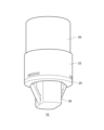
- FIG. 1 is a perspective view of a vibration damping device of an embodiment;
- FIG. It is an exploded view of a damping device. It is a perspective view of a fixing
- 4 is a perspective cross-sectional view of a rotating member and a gear member;
- FIG. FIG. 10 is a diagram for explaining the rotation operation of the gear member, and is a diagram showing a perspective view of the fixing portion and the gear member;
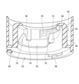
- FIG. FIG. 4 is a cross-sectional view of the vibration damping device in an unlocked state and a state in which the vibration damping portion protrudes most;
- FIG. 4 is a cross-sectional view of the vibration damping device in a locked state and a state in which the vibration damping portion is retracted to the maximum;
- FIG. 1 is a perspective view of the vibration damping device 10 of the embodiment.
- the vibration damping device 10 is fixed to an opening/closing member such as a door or a back door of a vehicle, and contacts a panel on the vehicle body side when the opening/closing member is closed.
- the vibration damping device 10 absorbs the impact when the opening/closing body is closed, suppresses the vibration of the opening/closing body when the opening/closing body is closed, and suppresses the generation of unpleasant noise due to the resonance of the opening/closing body.
- the vibration damping device 10 may be fixed to a fixed body such as a panel on the vehicle body side and come into contact with the opening/closing body. That is, the vibration damping device 10 is fixed to one of the opening/closing body and the fixed body, and can abut on the other of the opening/closing body and the fixed body. Further, the vibration damping device 10 is not limited to being fixed to an opening/closing body, and may be provided to a fixed body. In any case, the damping device 10 is interposed between the first member and the second member to suppress vibration of the second member with respect to the first member. For example, one of the first member and the second member is an opening/closing body, and the other is a fixed body.
- Vibration damping device 10 includes, as externally exposed parts, a fixing member 26 fixed to one of the first member and the second member, a cover 20 capable of coming into contact with the other of the first member and the second member, a rotating A member 22 and a washer 24 are provided.
- the fixing member 26 is fixed by being inserted into, for example, a mounting hole provided in the door of the vehicle.
- FIG. 2 is an exploded view of the damping device 10.
- the vibration damping device 10 includes a cover 20 , a rotating member 22 , a washer 24 , a fixing member 26 , a viscoelastic body 28 , a moving member 30 and a gear member 32 .
- the cover 20 and the viscoelastic body 28 function as a damping section 21 that exerts a damping function.
- the rotating member 22, the fixed member 26 and the gear member 32 function as a fixed side unit 23 fixed to one of the first member and the second member.
- a height adjustment mechanism is formed between the fixed-side unit 23 and the moving member 30 to movably hold the height of the moving member 30 with respect to the fixed-side unit 23 .
- the tooth portion 36 of the moving member 30 and the gear member 32 function as a height adjusting mechanism for adjusting the protrusion height of the damping portion 21 .
- the cover 20 is formed of a rubber material in a cup shape, covers the viscoelastic body 28 and is attached to the moving member 30 .
- the cover 20 is positioned at the tip of the vibration damping device 10 .
- the viscoelastic body 28 is formed in a cylindrical shape from a viscoelastic material, and is preferably formed from, for example, ethylene propylene diene rubber and 4-methyl-1-pentene/ ⁇ -olefin copolymer. Of course, the viscoelastic body 28 may be made of another viscoelastic material.
- the viscoelastic body 28 is mounted on the moving member 30 and accommodated within the cover 20 .
- the viscoelastic body 28 is made of a material different from that of the cover 20 and has a temperature characteristic different from that of the cover 20 . Thereby, the temperature range in which the damping function can be exhibited can be widened.
- the moving member 30 is axially movable with respect to the fixed-side unit 23 .
- the damping portion 21 attached to the moving member 30 moves axially together with the moving member 30 .
- the moving member 30 has a shaft portion 34 , a tooth portion 36 and a pedestal portion 38 .
- the shaft portion 34 is formed in a bar shape and inserted into the fixing member 26 .
- the tooth portions 36 are formed on both side surfaces of the shaft portion 34 along the axial direction.
- the pedestal portion 38 is formed in a disc shape at one end of the shaft portion 34 .
- the pedestal portion 38 has a peripheral edge recessed portion 40 that is recessed on the peripheral edge.
- the cover 20 is engaged with the peripheral recess 40 .
- the rotating member 22 is rotatably provided with respect to the fixed member 26 .
- a gear member 32 is mounted inside the rotating member 22 .
- the washer 24 is attached to the fixed member 26 .
- FIG. 3 is a perspective view of the fixing member 26.
- the fixing member 26 has a shaft portion 44 , an elastic locking portion 46 , a flange portion 48 , a convex portion 50 , a guide portion 52 , an insertion concave portion 54 , an insertion hole 56 and a notch portion 58 .
- a pair of elastic locking portions 46 are formed on both side surfaces of the shaft portion 44 .
- the elastic locking portion 46 is flexible and locks to the edge of the mounting hole of the opening/closing body.
- the convex portion 50 protrudes from the flange portion 48 and is formed in a substantially annular shape.
- a plurality of rectangular notch portions 58 are formed on the outer peripheral edge of the flange portion 48 .
- the shaft portion 34 of the moving member 30 can be inserted into the insertion hole 56 .
- the insertion concave portion 54 is formed in the convex portion 50, into which the tapered portion of the gear member 32 is inserted.
- the guide portion 52 is an inclined surface extending from the flange portion 48 toward the upper end side of the convex portion 50 . The guide portion 52 guides the rotation of the gear member 32 .
- FIG. 4 is a perspective cross-sectional view of the rotating member 22 and the gear member 32.
- FIG. FIG. 4 shows the gear member 32 attached to the rotating member 22 .
- the rotating member 22 has an inner wall portion 60 , an outer wall portion 62 , a gap 64 , a support portion 66 and an inwardly projecting portion 68 .
- the inner wall portion 60 and the outer wall portion 62 are arranged facing each other in the radial direction to form an annular gap 64 .
- the air gap 64 opens upward.
- the outer wall portion 62 is formed in a cylindrical shape and has a larger diameter than the inner wall portion 60 .
- a lower end portion of the outer wall portion 62 protrudes downward from the inner wall portion 60 .
- An inward projecting portion 68 projecting radially inward is formed at the lower end portion of the outer wall portion 62 .
- the inward projecting portion 68 is formed as an elastic piece supported on both sides and is radially displaceable. The inward projecting portion 68 passes through the notch portion 58 of the fixing member 26 and hooks on the flange portion 48 .
- a pair of inwardly projecting support portions 66 are formed on the inner peripheral surface of the inner wall portion 60 .
- a pair of support portions 66 are formed to extend in the axial direction with a predetermined distance therebetween.
- a pair of support portions 66 support the gear member 32 .
- the gear member 32 has a multi-stepped mountain portion 70 , an extended mountain portion 72 , an engaging portion 74 , a tapered portion 76 and an inclined portion 78 .
- the multi-step mountain portion 70 is formed on the inner peripheral surface of the gear member 32 .
- the extending peak portion 72 extends in the circumferential direction from the peak on the upper end side of the multi-stepped peak portion 70 .
- the multi-stepped mountain portion 70 and the extended mountain portion 72 can be engaged with the tooth portion 36 of the moving member 30 .
- the engaging portion 74 is recessed and engages the support portion 66 .
- the tapered portion 76 is formed at the circumferential end of the gear member 32 and can be inserted into the insertion recess 54 of the fixed member 26 .
- the inclined portion 78 is formed by shaving the corner of the lower end of the gear member 32 and is guided by the guide portion 52 of the fixed member 26 during rotation.
- the gear member 32 is attached to the rotating member 22 and forms teeth on the inner peripheral side of the rotating member 22 .
- FIG. 5 is a diagram for explaining the rotation operation of the gear member 32, and shows a perspective view of the fixed member 26 and the gear member 32.
- FIG. 5(a) shows the positional relationship between the fixing member 26 and the gear member 32 in the unlocked state
- FIG. 5(b) shows the positional relationship between the fixing member 26 and the gear member 32 in the locked state.
- the vibration damping device 10 is divided into a first assembly composed of the damping portion 21 and the moving member 30 and a second assembly composed of the rotating member 22 , the fixed member 26 and the gear member 32 .
- the first assembly is axially movable with respect to the second assembly in the unlocked state shown in FIG. 5(a) and axially movable relative to the second assembly in the locked state shown in FIG. 5(b). Can not.
- the moving member 30 of the first assembly is inserted into the rotating member 22 and the fixed member 26 of the second assembly.
- the extending peak portion 72 lightly supports the moving member 30, the moving member 30 can move in the axial direction by bending the extending peak portion 72.
- the rotating member 22 and the gear member 32 are rotated so that the multi-stepped ridge portion 70 of the gear member 32 engages with the toothed portion 36 of the moving member 30, and the multi-stepped ridge portion 70 is not flexed, so that the moving member 30 is held by the gear. It is locked by the member 32 and cannot be moved.
- the gear member 32 is placed on the flange portion 48 and is in a position before the moving member 30 is locked.
- the tapered portion 76 enters the insertion recess 54 .
- the inclined portion 78 is positioned in front of the guide portion 52 and is guided toward the upper side of the convex portion 50 when the gear member 32 rotates.
- the gear member 32 rotates with respect to the fixed member 26 and rests on the upper side of the convex portion 50.
- the multi-stepped mountain portion 70 engages with the tooth portion 36 of the moving member 30 instead of the extended mountain portion 72 to hold the moving member 30 .
- the gear member 32 of the fixed-side unit 23 can be held at the position to which the moving member 30 has moved.
- the moving member 30 By rotating the rotating member 22 and the gear member 32 in this way, the moving member 30 is locked or unlocked, and in the unlocked state, the protrusion height of the damping portion 21 with respect to the fixed-side unit 23 is adjusted. becomes possible.
- the moving member 30 and the fixed-side unit 23 cooperate to adjust the protrusion height of the vibration damping portion 21 and move the vibration damping portion 21 axially with respect to the fixed-side unit 23 .
- the moving member 30 and the gear member 32 of the fixed-side unit 23 function as a height adjustment mechanism that adjusts the height of the damping section 21 with respect to the fixed-side unit 23 . This makes it possible to absorb manufacturing errors occurring in the gap between the opening/closing member and the fixed member, thereby stabilizing the damping performance.
- FIG. 6 is a cross-sectional view of the vibration damping device 10 in an unlocked state with the vibration damping portion 21 protruding to the maximum. Also, the damping device 10 is attached to the attachment hole 12 a of the opening/closing body 12 . This is a state in which the vibration damping device 10 has been completely assembled and is in a delivery state. The moving member 30 connects to the fixed member 26 and/or the gear member 32 in the delivered state.
- the cover 20 has a locking portion 80 , a column portion 82 and an outer cylinder end portion 84 .
- the locking portion 80 is formed in the shape of a groove extending in the circumferential direction on the inner peripheral surface of the cover 20 .
- the engaging portion 80 engages with the peripheral recessed portion 40 of the moving member 30 . This can prevent the engaging portion 80 of the cover 20 from interfering with the viscoelastic body 28 .
- the column portion 82 is positioned in the center inside the cover 20 and is formed to hang down and is inserted into the through hole 42 of the viscoelastic body 28 .
- the viscoelastic body 28 exerts a damping function at low temperatures
- the column portion 82 exerts a damping function at high temperatures, so that the damping function can be exerted over a wide temperature range.
- the viscoelastic body 28 and the column portion 82 are placed on the pedestal portion 38 , and the viscoelastic body 28 surrounds the column portion 82 .
- the cross-sectional areas along the radial direction of the viscoelastic body 28 and the column portion 82 are provided to be equal. As a result, a stable damping function can be exhibited both at low temperatures and at high temperatures.
- the end portion 84 of the outer cylinder extends further toward the fixing member 26 than the engaging portion 80 and is positioned at the open end of the cover 20 .
- the outer tube end portion 84 is slightly recessed inside the outer wall portion 62 . As a result, it is possible to prevent the outer cylinder end portion 84 from being caught by the edge of the outer wall portion 62 when adjusting the height. It should be noted that the outer cylinder end portion 84 does not have to enter the outer wall portion 62 in the unlocked state and the vibration damping portion 21 protruding to the maximum.
- the height of the flange portion 48 and the protrusion portion 50 adjusts the projecting height of the vibration damping portion 21 to a constant value, so that the vibration damping device 10 is fixed to the fixed body when the opening/closing body 12 is closed. It can be brought into contact with a moderate load. As a result, when the opening/closing body 12 vibrates as the vehicle travels, the amount of axial deflection of the vibration damping portion 21 can be suppressed, and the vibration damping function can be stabilized.
- the outer wall portion 62 is provided so as to be higher than the inner wall portion 60 in the axial direction.
- the outer wall portion 62 can cover the internal structure of the vibration damping device 10 to prevent foreign matter from entering the interior.
- the viscoelastic body 28 is provided so as not to overlap the peripheral recess 40 in the axial direction.
- FIG. 7 is a cross-sectional view of the vibration damping device 10 in a locked state and with the vibration damping portion 21 retracted to the maximum.
- the damping portion 21 and the moving member 30 are fully retracted, the outer cylinder end portion 84 of the cover 20 enters the gap 64 of the rotating member 22 .
- the outer wall portion 62 surrounds the outer cylinder end portion 84 regardless of the extent to which the damping portion 21 is pulled. Further, the outer wall portion 62 surrounds the outer cylinder end portion 84 in a state in which the damping portion 21 is in contact with the other of the opening/closing member 12 and the fixed member. This is because the state in which the vibration damping portion 21 is in contact with the other of the opening/closing member 12 and the fixed member is in the case of actual use and is in the locked state.
- the viscoelastic body 28 is contracted in the axial direction, the viscoelastic body 28 bends radially outward. There is a risk that it will be pushed radially outward and come off.
- the outer wall portion 62 surrounds the end portion 84 of the outer cylinder, even when the viscoelastic body 28 is bent radially outward, expansion of the diameter of the end portion 84 of the outer cylinder is suppressed, and the locking portion 80 is engaged. It is possible to prevent the stopper from coming off. Moreover, since it is not necessary to provide a wall for restricting the diameter expansion of the viscoelastic body 28 on the outer peripheral side of the viscoelastic body 28, the outer diameter of the vibration damping device 10 can be made small.
- the end portion 62a of the outer wall portion 62 is positioned above the locking portion 80, and the outer wall portion 62 surrounds the locking portion 80. Thereby, the locking of the locking portion 80 can be maintained.
- the vibration damping section 21 is composed of the cover 20 and the viscoelastic body 28, but the present invention is not limited to this embodiment, and the vibration damping section 21 may be composed of one member.
- the fixed side unit 23 is configured by the fixed member 26, the rotating member 22 and the gear member 32, but it is not limited to this.
- the fixing member 26 may have a female thread
- the moving member 30 may have a male thread
- the female thread of the fixing member 26 and the male thread of the moving member 30 may be screwed together to adjust the height.
- the fixed-side unit 23 is composed only of the fixed member 26 .
- a locking member that locks onto teeth 36 of moving member 30 may be substituted for rotating member 22 and gear member 32 .
- the lock member may have a locking pawl that locks onto the tooth portion 36 and a rotating shaft portion perpendicular to the axial direction, and may be configured to take a locked state and an unlocked state by rotation.
- the present invention relates to a damping device that damps vibration.
- Vibration damping device 10 Opening and closing body 12a Mounting hole 20 Cover 21 Vibration damping part 22 Rotating member 24 Washer 26 Fixed member 28 Viscoelastic body 30 Moving member 32 Gear member 34 Shaft 36 Tooth part, 38 pedestal part, 40 peripheral concave part, 42 through hole, 44 shaft part, 46 elastic locking part, 48 flange part, 50 convex part, 52 guide part, 54 insertion concave part, 56 insertion hole, 58 notch part, 60 inner wall portion, 62 outer wall portion, 64 void, 66 support portion, 68 inward protruding portion, 70 multi-stepped mountain portion, 72 extended mountain portion, 74 engaging portion, 76 tapered portion, 78 inclined portion, 80 locking portion, 82 Column portion, 84 Outer cylinder end portion.
Landscapes
- Engineering & Computer Science (AREA)
- General Engineering & Computer Science (AREA)
- Mechanical Engineering (AREA)
- Chemical & Material Sciences (AREA)
- Combustion & Propulsion (AREA)
- Physics & Mathematics (AREA)
- Acoustics & Sound (AREA)
- Aviation & Aerospace Engineering (AREA)
- Transportation (AREA)
- Vibration Prevention Devices (AREA)
- Vibration Dampers (AREA)
- Closing And Opening Devices For Wings, And Checks For Wings (AREA)
- Springs (AREA)
Abstract
Description
Claims (2)
- 第1部材および第2部材の間に介在して前記第1部材に対する前記第2部材の振動を抑制する制振装置であって、
前記第1部材および前記第2部材の一方に固定される固定側ユニットと、
前記第1部材および前記第2部材の他方に当接する制振部と、
前記固定側ユニットに対して移動可能に設けられる移動部材と、を備え、
前記固定側ユニットと前記移動部材との間には、前記固定側ユニットに対する前記移動部材の高さを移動可能に保持する高さ調整機構が形成されており、
前記制振部は、
略カップ状に形成され、前記移動部材に固定されるカバーと、
前記カバーとは異なる材料で形成され、前記カバー内に収容される粘弾性体と、を有することを特徴とする制振装置。 - 前記移動部材は、前記粘弾性体を載置する台座部を有し、
前記カバーは、
前記台座部の縁に係止する係止部と、
前記係止部よりも前記固定側ユニットに向かって延出している外筒端部と、を有し、
前記固定側ユニットは、前記制振部が前記第1部材および前記第2部材の他方に当接した状態で、前記外筒端部を環囲する外壁部を有することを特徴とする請求項1に記載の制振装置。
Priority Applications (2)
| Application Number | Priority Date | Filing Date | Title |
|---|---|---|---|
| CN202280050150.6A CN117716143A (zh) | 2021-07-28 | 2022-07-22 | 减振装置 |
| JP2023538497A JP7521126B2 (ja) | 2021-07-28 | 2022-07-22 | 制振装置 |
Applications Claiming Priority (2)
| Application Number | Priority Date | Filing Date | Title |
|---|---|---|---|
| JP2021123610 | 2021-07-28 | ||
| JP2021-123610 | 2021-07-28 |
Publications (1)
| Publication Number | Publication Date |
|---|---|
| WO2023008342A1 true WO2023008342A1 (ja) | 2023-02-02 |
Family
ID=85086891
Family Applications (1)
| Application Number | Title | Priority Date | Filing Date |
|---|---|---|---|
| PCT/JP2022/028525 Ceased WO2023008342A1 (ja) | 2021-07-28 | 2022-07-22 | 制振装置 |
Country Status (3)
| Country | Link |
|---|---|
| JP (1) | JP7521126B2 (ja) |
| CN (1) | CN117716143A (ja) |
| WO (1) | WO2023008342A1 (ja) |
Citations (5)
| Publication number | Priority date | Publication date | Assignee | Title |
|---|---|---|---|---|
| JP2002021900A (ja) * | 2000-07-06 | 2002-01-23 | Nifco Inc | 緩衝装置 |
| US20160245008A1 (en) * | 2013-10-14 | 2016-08-25 | A Raymond Et Cie | Buffer device having a self-adjusting abutment |
| KR20190007545A (ko) * | 2017-07-12 | 2019-01-23 | 현대자동차주식회사 | 테일 게이트 팝업용 오버슬램범퍼 장치 |
| WO2021075370A1 (ja) * | 2019-10-17 | 2021-04-22 | 株式会社パイオラックス | 制振装置 |
| JP2022038050A (ja) * | 2020-08-26 | 2022-03-10 | 株式会社ニフコ | 高さ調節装置 |
Family Cites Families (1)
| Publication number | Priority date | Publication date | Assignee | Title |
|---|---|---|---|---|
| FR2886329B1 (fr) | 2005-05-27 | 2007-06-29 | Coutier Moulage Gen Ind | Butee auto-reglable en hauteur pour un ouvrant de vehicule automobile |
-
2022
- 2022-07-22 WO PCT/JP2022/028525 patent/WO2023008342A1/ja not_active Ceased
- 2022-07-22 JP JP2023538497A patent/JP7521126B2/ja active Active
- 2022-07-22 CN CN202280050150.6A patent/CN117716143A/zh active Pending
Patent Citations (5)
| Publication number | Priority date | Publication date | Assignee | Title |
|---|---|---|---|---|
| JP2002021900A (ja) * | 2000-07-06 | 2002-01-23 | Nifco Inc | 緩衝装置 |
| US20160245008A1 (en) * | 2013-10-14 | 2016-08-25 | A Raymond Et Cie | Buffer device having a self-adjusting abutment |
| KR20190007545A (ko) * | 2017-07-12 | 2019-01-23 | 현대자동차주식회사 | 테일 게이트 팝업용 오버슬램범퍼 장치 |
| WO2021075370A1 (ja) * | 2019-10-17 | 2021-04-22 | 株式会社パイオラックス | 制振装置 |
| JP2022038050A (ja) * | 2020-08-26 | 2022-03-10 | 株式会社ニフコ | 高さ調節装置 |
Also Published As
| Publication number | Publication date |
|---|---|
| CN117716143A (zh) | 2024-03-15 |
| JP7521126B2 (ja) | 2024-07-23 |
| JPWO2023008342A1 (ja) | 2023-02-02 |
Similar Documents
| Publication | Publication Date | Title |
|---|---|---|
| US7393111B2 (en) | Pivoting outside mirror for a motor vehicle | |
| KR20170008555A (ko) | 차량용 오버슬램 범퍼 | |
| US8720847B2 (en) | External articulation mechanism with a noise-dampening support element | |
| KR102603073B1 (ko) | 개폐체의 잠금 장치 | |
| CN104520605A (zh) | 缓冲装置 | |
| WO2016181994A1 (ja) | 緩衝装置 | |
| CN112900989B (zh) | 机动车门锁 | |
| US20240301937A1 (en) | Damper | |
| JP7521126B2 (ja) | 制振装置 | |
| JP7282471B2 (ja) | 制振装置 | |
| JP7582853B2 (ja) | シェード装置の一部組立機構 | |
| KR20180088253A (ko) | 차량의 조향컬럼 | |
| JP2022087760A (ja) | コンソールボックス | |
| JP2019190624A (ja) | クッションクリップ | |
| KR100435863B1 (ko) | 자동차용 스트라이커 | |
| JP2014020015A (ja) | スライドドアの拘束装置 | |
| JP2023011952A (ja) | 制振装置 | |
| JP5828692B2 (ja) | 自動車用開閉体の振動防止装置 | |
| JP7777483B2 (ja) | 制振装置 | |
| JP2024090974A (ja) | 制振装置 | |
| CN222276486U (zh) | 缓冲器 | |
| JP7846557B2 (ja) | インレットボックスユニット | |
| KR101491178B1 (ko) | 차량용 사이드미러 홀더 | |
| JP2832514B2 (ja) | 樹脂製軸受の固定構造 | |
| JP2019142425A (ja) | キャップ装置 |
Legal Events
| Date | Code | Title | Description |
|---|---|---|---|
| 121 | Ep: the epo has been informed by wipo that ep was designated in this application |
Ref document number: 22849404 Country of ref document: EP Kind code of ref document: A1 |
|
| DPE2 | Request for preliminary examination filed before expiration of 19th month from priority date (pct application filed from 20040101) | ||
| WWE | Wipo information: entry into national phase |
Ref document number: 202280050150.6 Country of ref document: CN |
|
| WWE | Wipo information: entry into national phase |
Ref document number: 2023538497 Country of ref document: JP |
|
| NENP | Non-entry into the national phase |
Ref country code: DE |
|
| 122 | Ep: pct application non-entry in european phase |
Ref document number: 22849404 Country of ref document: EP Kind code of ref document: A1 |