WO2016181994A1 - 緩衝装置 - Google Patents
緩衝装置 Download PDFInfo
- Publication number
- WO2016181994A1 WO2016181994A1 PCT/JP2016/064005 JP2016064005W WO2016181994A1 WO 2016181994 A1 WO2016181994 A1 WO 2016181994A1 JP 2016064005 W JP2016064005 W JP 2016064005W WO 2016181994 A1 WO2016181994 A1 WO 2016181994A1
- Authority
- WO
- WIPO (PCT)
- Prior art keywords
- case member
- buffer member
- shock absorber
- spring
- shock
- Prior art date
Links
Images


Classifications
-
- F—MECHANICAL ENGINEERING; LIGHTING; HEATING; WEAPONS; BLASTING
- F16—ENGINEERING ELEMENTS AND UNITS; GENERAL MEASURES FOR PRODUCING AND MAINTAINING EFFECTIVE FUNCTIONING OF MACHINES OR INSTALLATIONS; THERMAL INSULATION IN GENERAL
- F16F—SPRINGS; SHOCK-ABSORBERS; MEANS FOR DAMPING VIBRATION
- F16F1/00—Springs
- F16F1/02—Springs made of steel or other material having low internal friction; Wound, torsion, leaf, cup, ring or the like springs, the material of the spring not being relevant
- F16F1/04—Wound springs
- F16F1/12—Attachments or mountings
- F16F1/128—Attachments or mountings with motion-limiting means, e.g. with a full-length guide element or ball joint connections; with protective outer cover
-
- F—MECHANICAL ENGINEERING; LIGHTING; HEATING; WEAPONS; BLASTING
- F16—ENGINEERING ELEMENTS AND UNITS; GENERAL MEASURES FOR PRODUCING AND MAINTAINING EFFECTIVE FUNCTIONING OF MACHINES OR INSTALLATIONS; THERMAL INSULATION IN GENERAL
- F16F—SPRINGS; SHOCK-ABSORBERS; MEANS FOR DAMPING VIBRATION
- F16F1/00—Springs
- F16F1/02—Springs made of steel or other material having low internal friction; Wound, torsion, leaf, cup, ring or the like springs, the material of the spring not being relevant
- F16F1/04—Wound springs
- F16F1/12—Attachments or mountings
-
- F—MECHANICAL ENGINEERING; LIGHTING; HEATING; WEAPONS; BLASTING
- F16—ENGINEERING ELEMENTS AND UNITS; GENERAL MEASURES FOR PRODUCING AND MAINTAINING EFFECTIVE FUNCTIONING OF MACHINES OR INSTALLATIONS; THERMAL INSULATION IN GENERAL
- F16F—SPRINGS; SHOCK-ABSORBERS; MEANS FOR DAMPING VIBRATION
- F16F7/00—Vibration-dampers; Shock-absorbers
-
- B—PERFORMING OPERATIONS; TRANSPORTING
- B60—VEHICLES IN GENERAL
- B60R—VEHICLES, VEHICLE FITTINGS, OR VEHICLE PARTS, NOT OTHERWISE PROVIDED FOR
- B60R7/00—Stowing or holding appliances inside vehicle primarily intended for personal property smaller than suit-cases, e.g. travelling articles, or maps
- B60R7/04—Stowing or holding appliances inside vehicle primarily intended for personal property smaller than suit-cases, e.g. travelling articles, or maps in driver or passenger space, e.g. using racks
- B60R7/06—Stowing or holding appliances inside vehicle primarily intended for personal property smaller than suit-cases, e.g. travelling articles, or maps in driver or passenger space, e.g. using racks mounted on or below dashboards
Definitions
- the present invention relates to a shock absorber for reducing the impact of, for example, closing a lid of a glove box.
- a shock absorber is provided to suppress vibration.
- Patent Document 1 includes a casing, a rubber load receiving member slidably mounted on the casing, and a spring biased in a direction away from the bottom of the load receiving member. Buffer parts are described.
- the said casing has the anchor support
- the load receiving member is disposed in the anchor column portion of the casing, and the outer periphery of the load receiving member is in sliding contact with the inner periphery of the anchor column portion.
- a shaft portion projects from the bottom portion of the casing, and a spring is supported on the outer periphery of the shaft portion.
- the load receiving member has a cylindrical shape on the base end side, a spring is inserted into the inner periphery thereof, and the upper end portion of the shaft portion is disposed.
- a spring is inserted into the inner periphery of the load receiving member, and the shaft portion of the casing is disposed in the spring.
- the shaft portion does not function as a guide when the load receiving member slides.
- the load receiving member is slidably guided only by the anchor column portion of the casing.
- the load receiving member tends to tilt and the guide may not be stably provided.
- the load receiving member is placed on the bottom of the casing. It becomes easy to attach, and the amount of sliding of the load receiving member is reduced, so that the buffer performance is lowered.
- an object of the present invention is to provide a buffering measure that can improve the guide performance while securing the sliding amount of the buffering member.
- the present invention is a shock absorber arranged between a fixed member and a moving body that moves so as to move closer to and away from the fixed member, and cushions the movement of the moving body,
- a case member a shock-absorbing member that is slidably attached to the case member, receives an impact by contacting the moving body or the fixed member, and biases the shock-absorbing member in a direction away from the case member
- the case member includes a bottom portion, a support portion that supports one end of the spring, a shaft portion that protrudes from the bottom portion, and a peripheral wall that is disposed on the outer periphery of the shaft portion and receives the buffer member.
- the buffer member includes an inner cylinder into which the shaft portion of the case member is inserted, an outer cylinder disposed on an outer periphery of the inner cylinder, and a spring receiving portion that supports the other end of the spring. And between the case member and the buffer member A retaining means for retaining the buffer member from the case member is provided, and an outer periphery of the outer cylinder of the buffer member is disposed on an inner periphery of the peripheral wall of the case member. In addition to providing a guide, the inner periphery of the inner cylinder of the buffer member is disposed on the outer periphery of the shaft portion of the case member to form a second guide when the buffer member slides.
- the first guide and the second guide are disposed so as to overlap each other in the axial direction when the case member is viewed in a cross section along the axial direction. .
- a cylindrical space is formed between the inner cylinder and the outer cylinder of the buffer member, and the buffer member slides in a direction away from the support portion of the case member.
- the cylindrical space is disposed axially outward of the case member in a state where the buffer member is prevented from being detached from the case member by the retaining means. It is preferable that the end portion in the direction outward direction is configured to form the spring receiving portion.
- the retaining means includes a diameter-expanded portion provided on the distal end portion of the shaft portion of the case member and a slit on the proximal end side of the inner cylinder of the shock-absorbing member. It is preferable that it consists of an engaging claw that is formed so as to be able to be bent via the diameter and that can be engaged with the enlarged diameter portion.
- the shock-absorbing member includes a main body having the inner cylinder and the outer cylinder, and a cap made of an elastic material attached to the outer periphery of the distal end portion of the main body. Is provided with a projecting portion protruding into the inner cylinder, the buffer member is pressed and slides against the elastic biasing force of the spring, and the buffer member contacts the bottom of the case member. It is preferable that the protrusion of the cap is configured to come into contact with the tip of the shaft portion of the case member before contacting.
- the buffer member slides while compressing the spring, so that the movable member is moved by the elastic biasing force of the spring. It can absorb and buffer the impact force of the body and the vibration of the moving body.
- the outer periphery of the outer cylinder of the buffer member is arranged on the inner periphery of the peripheral wall of the case member to form a first guide when the buffer member slides, and the inner periphery of the inner cylinder of the buffer member is arranged on the outer periphery of the shaft portion of the case member
- the second guide is formed when the buffer member is slid, and the buffer member is guided by the two guides. Therefore, the buffer member can be firmly guided while securing the slide amount of the buffer member.
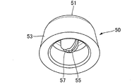
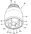
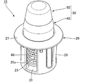
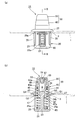
- FIG. 1 It is a disassembled perspective view which shows one Embodiment of the buffering device which concerns on this invention. It is a perspective view of the cap which comprises the buffer member of the buffer device. It is a perspective view of the main body which comprises the buffer member of the buffer device. It is a perspective view of the buffer device.
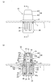
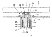
- the state which attached the same shock absorber to the fixing member is shown, (a) is the front view, (b) is a sectional view in the AA arrow line of (a).
- the state which attached the buffering device to the fixing member is shown, (a) is the side view, (b) is sectional drawing in the BB arrow line of (a).
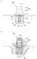
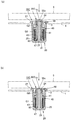
- FIG. 5 shows another embodiment of the shock absorber according to the present invention, in which (a) is a side view of the shock absorber attached to a fixing member, and (b) is a cross-sectional view taken along the line CC of FIG. It is.
- the other embodiment of the shock absorber concerning this invention is shown, (a) is a side view of the state which attached the shock absorber to the fixing member, (b) is along the DD arrow line of (a). It is sectional drawing.
- FIG. 6 is a sectional view showing still another embodiment of the shock absorber according to the present invention, in which the shock absorber is attached to a fixing member.
- the use state of the shock absorber is shown.
- (A) is a cross-sectional view of the state where the buffer member is pushed by the moving body from the state shown in FIG. 10, and
- (b) is a state where the buffer member is further moved from the state of (a). It is sectional drawing of the pushed state.
- the shock absorber 10 is disposed between the fixed member 1 and the moving body 5 that moves so as to approach and separate from the fixed member 1.
- the moving body 5 comes into contact with it to buffer its movement.
- the fixing member 1 include a vehicle glove box, a vehicle frame, and a vehicle panel.
- the moving body 5 includes a lid that opens and closes with respect to the opening of the glove box, and various vehicle doors (side doors). And hatchback doors) are not particularly limited.
- the fixing member 1 is formed with a round hole-like mounting hole 3 (see FIG. 1).
- a shock absorber 10 of this embodiment is mounted on a case member 20 attached to a fixing member 1 and slidably mounted on the case member 20, and abuts against a moving body 5 to apply an impact thereto.
- a buffer member 30 is provided, and a spring 60 that urges the buffer member 30 in a direction away from the case member 20 (here, the movable body 5 side).
- the case member 20 is attached to the attachment hole 3 of the fixing member 1, and thereby the shock absorber 10 is attached to the fixing member 1.
- a moving body such as a lid or a door is used. 5 may be provided, and the shock absorber 10 may be attached to the movable body 5 side. If the shock absorber 10 is arranged between the fixed member and the movable body, there is no particular limitation. Not.
- the case member 20 includes a bottom portion 21, a support portion that supports one end of the spring 60, a shaft portion 23 that protrudes from the bottom portion 21, It has the surrounding wall 25 which is arrange
- the case member 20 of this embodiment has a substantially cylindrical shape with a bottom as a whole, and has a substantially disc-shaped bottom portion 21, and one end of a spring 60 is supported by the bottom portion 21. ing. That is, in this embodiment, the bottom portion 21 forms a “support portion” in the present invention.
- the support part of the spring 60 may be provided separately from the bottom part 21 by providing an annular protrusion, an arcuate rib, or the like at a predetermined interval from the bottom part 21 on the inner periphery of the peripheral wall 25.
- the shaft portion 23 protrudes from the center at a predetermined height, and the shaft portion 23 is inserted into the spring 60. (See FIG. 5B). Further, a peripheral wall 25 having a substantially cylindrical shape is erected at a predetermined length in the same direction as the shaft part 23 from the outer periphery of the shaft part 23 and from the periphery of the bottom part 21. The buffer member 30 and the spring 60 are received on the inner periphery.
- notches 25a and 25a are formed at predetermined positions along the circumferential direction of the peripheral wall 25 along the axial direction of the case member 20, that is, along the axial direction of the shaft 23. (See FIG. 1 and FIG. 6 (b)). Further, from the outer periphery of the distal end portion in the standing direction of the peripheral wall 25, an annular flange portion 27 that abuts on the front side peripheral edge of the mounting hole 3 of the fixing member 1 protrudes toward the outer diameter direction. Furthermore, from the position which is the outer periphery of the surrounding wall 25 and orthogonal to the notch portions 25a and 25a in the circumferential direction, the engaging portions 29 and 29 are engaged with the peripheral edge of the mounting hole 3 of the fixing member 1.
- locking part 29 has the top part 29a which protruded high toward the outer-diameter direction of the surrounding wall 25 (refer FIG.5 (b)), and the taper which the diameter of the bottom part 21 side is gradually reduced from this top part 29a.
- the flange portion 27 side from the top portion 29a has a taper shape that is steeply inclined to reduce the diameter.
- the case member has a bottomed substantially cylindrical shape, but may have, for example, a bottomed rectangular tube shape, and can be attached to a fixed member or a moving body. And if it is a structure which can support a buffer member so that a slide is possible, it will not specifically limit.
- the buffer member 30 slidably attached to the case member 20 will be described.
- the buffer member 30 is attached to the case member 20 and slides along the axial direction of the case member 20 so as to approach or separate from the bottom 21 of the case member 20.
- the buffer member 30 is disposed on the inner cylinder 41 into which the shaft portion 23 of the case member 20 is inserted, and on the outer periphery of the inner cylinder 41.
- the buffer member 30 in this embodiment has a main body 40 having an inner cylinder 41 and an outer cylinder 43 and a cap 50 made of an elastic material attached to the outer periphery of the distal end portion of the main body 40.
- the main body 40 includes a substantially cylindrical inner cylinder 41 into which the shaft portion 23 of the case member 20 is inserted, and a concentric outer periphery of the inner cylinder 41.
- a space 45 is formed.
- a plurality of annular protrusions 49 are provided on the outer periphery of the inner cylinder 41 on the tip end side in the axial direction. Further, as shown in FIG. 3, a plurality of slits 46 extending in the axial direction are formed in the circumferential direction on the base end side of the inner cylinder 41 in the axial direction. Thus, a plurality of engaging claws 47 that can be bent are formed (four in this case). Each engaging claw 47 has a shape in which a distal end portion 47 a protrudes in the inner diameter direction of the inner cylinder 41.
- each engagement claw 47 is provided with a tapered surface 47b that gradually decreases the distal end portion 47a toward the inner diameter direction (FIGS. 3 and 3). 5 (b)), and serves as a guide when the shaft portion 23 is inserted into the plurality of engaging claws 47.
- annular spring receiving portion 43a is projected from the outer periphery in the axial direction of the inner cylinder 41, and the outer cylinder is interposed through the spring receiving portion 43a.
- 43 extends so as to be concentric with the inner cylinder 41 so as to be slightly shorter than a portion including the engaging claw 47 of the inner cylinder 41, and the outer cylinder 43 and the inner cylinder 41.
- the cylindrical space 45 is defined between the two.
- the buffer member 30 is in a direction in which the other end of the spring 60 supported at one end by the bottom portion 21 of the case member 20 is inserted into the cylindrical space 45 and close to the bottom portion 21 of the case member 20.
- the other end of the spring 60 is supported in contact with the axially outer end of the cylindrical space 45, that is, the spring receiving portion 43 a, and the plurality of engaging claws 47 of the inner cylinder 41. Since the front end portion 47a of the shaft member 23 is engaged with the enlarged diameter portion 24 of the shaft portion 23, the case member 20 is prevented from coming off against the urging force of the spring 60 (FIGS. 5B and 6). (See (b)). That is, in this embodiment, the engaging claw 47 and the diameter-expanded portion 24 of the shaft portion 23 constitute “a retaining means” in the present invention.
- the retaining means is not limited to the above structure, and the installation location is not particularly limited. In other words, any structure may be used as long as it is between the case member and the buffer member and can prevent the buffer member from being detached from the case member.
- the other structure of the retaining means will be described in the embodiments shown in FIGS.
- the outer periphery of the outer cylinder 43 of the buffer member 30 is disposed on the inner periphery of the peripheral wall 25 of the case member 20,
- the first guide G1 when the buffer member 30 is slid is formed, and the inner periphery of the inner cylinder 41 of the buffer member 30 is arranged on the outer periphery of the shaft portion 23 of the case member 20, so that the second when the buffer member 30 is slid. It is comprised so that the guide G2 may be made.
- the outer diameter of the outer cylinder 43 is formed to a size that is substantially matched to the inner diameter of the peripheral wall 25 of the case member 20.
- the inner diameter of the inner cylinder 41 is formed to have a size substantially matching the outer diameter of the enlarged diameter portion 24 of the shaft portion 23 of the case member 20, and the bottom portion of the case member 20.
- the guide at the time of sliding of the buffer member is the inner periphery of the peripheral wall of the case member or the case member when the buffer member is inclined at a predetermined angle with respect to the axis of the case member at the time of sliding of the buffer member. It is meant to slide while restricting the further inclination of the buffer member.
- a predetermined gap may be formed between the circumference and the outer circumference of the outer cylinder 43, or between the outer circumference of the shaft portion 23 and the inner circumference of the inner cylinder 41.
- the buffer member 30 slides in a direction away from the bottom portion 21 of the case member 20, and the retaining means (here, the engaging claw 47 and the shaft portion 23).
- the cylindrical space 45 of the buffer member 30 is disposed on the outer side in the axial direction of the case member 20 in a state where the buffer member 30 is prevented from being detached from the case member 20 by the enlarged diameter portion 24).
- the axially outward end of the cylindrical space 45 is configured to form a spring receiving portion 45a.
- the cap 50 attached to the main body 40 is made of an elastic material such as rubber or elastic elastomer, and has a substantially disk-like contact that contacts the moving body 5.
- a portion 51 and a peripheral wall 53 extending so as to gradually increase in diameter from the periphery of the corresponding contact portion 51.
- a plurality of annular recesses 53 a are formed on the inner periphery of the peripheral wall 53, and the cap 50 is attached to the main body 40 by engaging with the annular protrusions 49 of the inner cylinder 41. (See FIG. 5B and FIG. 6B).
- a projecting portion 55 projecting into the inner cylinder 41 of the main body 40 protrudes from the inner surface side (main body 40 side) of the abutting portion 51 of the cap 50, and the diameter of the axial end of the shaft portion 23 is increased.
- the portion 24 is elastically abutted while being deformed (see FIG. 7).
- the protrusion 55 of this embodiment has a shape divided into a plurality by slits 57 extending in the axial direction (here, divided into two), and the buffer member 30 is pushed into the shaft. When it comes into contact with the enlarged diameter portion 24 of the portion 23, it is elastically deformed so as to be crushed (see FIG. 7).
- the buffer member 30 has a two-part structure including the main body 40 and the cap 50.
- the buffer member 30 may have a one-part structure formed of rubber or the like.
- the structure is not particularly limited as long as it has a space and can support the other end of the spring 60.
- the shock absorber 10 can be assembled as follows, for example.
- the cap 55 is put on the tip end side in the axial direction of the main body 40 of the buffer member 30 and the annular recess 53a is engaged with the annular projection 49, whereby the projection 55 is disposed in a projecting manner in the inner cylinder 41.
- the cap 50 is attached to the main body 40, and the buffer member 30 can be obtained.
- the spring 60 is accommodated and disposed in the peripheral wall 25 of the case member 20, the shaft portion 23 is inserted into the spring 60, and one end of the spring 60 is brought into contact with and supported by the bottom portion 21. In this state, the other end of the spring 60 protrudes from the opening on the front end side in the axial direction of the case member 20 by a predetermined length.
- the shaft portion 23 of the case member 20 is aligned with the center in the inner diameter direction of the plurality of engaging claws 47 of the buffer member 30 and the other end of the spring 60 is aligned with the cylindrical space 45 of the buffer member 30. Then, the buffer member 30 is pushed into the case member 20. Then, the distal end portion 47 a is pressed by the enlarged diameter portion 24 of the shaft portion 23, the plurality of engaging claws 47 are pushed and expanded, and the enlarged diameter portion 24 of the shaft portion 23 is gradually inserted into the inner cylinder 41. At the same time, the other end of the spring 60 is inserted into the cylindrical space 45.
- each engaging claw 47 is elastically restored, and the distal end portion 47a is a step of the enlarged diameter portion 24 of the axial portion 23.
- the shaft portion 23 is inserted into the inner cylinder 41 and the other end of the spring 60 inserted into the cylindrical space 45 is engaged with the portion 24 b. Abutting on and supported by the portion 43a.
- the spring 60 is compressed and is interposed between the case member 20 and the buffer member 30, and the case member 20 is slidably mounted while the buffer member 30 is prevented from coming off. (See FIG. 5B and FIG. 6B).
- the buffer member 30 is urged toward the movable body 5 by the spring 60, and the buffer member 30 is slid in a direction away from the bottom 21 of the case member 20 (FIG. 5 ( b) and FIG. 6B).
- the mounting hole 3 of the fixing member 1 By inserting and pushing the case member 20 of the shock absorber 10 assembled as described above from the front side of the mounting hole 3 of the fixing member 1, as shown in FIGS. 5 (b) and 6 (a), the mounting hole 3, the flange portion 27 abuts on the front peripheral edge, and the engaging portion 29 engages with the rear peripheral edge of the attachment hole 3, so that the shock absorber 10 can be attached to the fixing member 1.
- the moving body 5 moves in the direction in which the moving body 5 approaches the fixed member 1 (for example, moves in the direction in which the lid closes with respect to the opening of the glove box).
- the shock absorber 30 collides with the contact portion 51 of the cap 50 of the shock absorber 30 and is pressed, the shock absorber 30 compresses the spring 60 against the urging force of the spring 60 and the shock absorber 30 is compressed into the case member 20. Therefore, the impact force of the movable body 5 can be absorbed and buffered by the elastic urging force of the spring 60.
- the moving body 5 vibrates in a state where the moving body 5 receives the elastic force of the spring 60 (for example, a state where the glove box lid is closed), the vibration can be absorbed and buffered.
- the protrusion 55 of the cap 50 is elastically deformed by elastic contact with the enlarged diameter portion 24 of the shaft portion 23.
- the outer periphery of the outer cylinder 43 of the buffer member 30 is disposed on the inner periphery of the peripheral wall 25 of the case member 20,
- the first guide G1 when the buffer member 30 is slid is formed, and the inner periphery of the inner cylinder 41 of the buffer member 30 is arranged on the outer periphery of the shaft portion 23 of the case member 20, so that the second when the buffer member 30 is slid. Since the guide G2 is formed, the buffer member 30 can be slid and guided by the two guides G1 and G2.
- the first guide G ⁇ b> 1 is provided on the outer periphery of the peripheral wall 25 of the case member 20 and the outer periphery of the outer cylinder 43 of the buffer member 30, and the outer periphery of the shaft portion 23 of the case member 20 and the buffer member 30.
- the second guide G2 is provided on the inner periphery of the inner cylinder 41, the outer surface (spring support surface) of the bottom portion 21 of the case member 20 even if the buffer member 30 slides in a direction close to the bottom portion 21 of the case member 20.
- the shaft portion 23 of the shock absorber 30 can be structured so as not to protrude from the opposite surface). As a result, the overall axial length of the shock absorber 10 can be shortened, and the mounting space for the shock absorber 10 can be reduced. Can be reduced.
- the buffer member 30 slides away from the bottom 21 of the case member 20 to prevent the retaining member (here, the engaging claw). 47 and the enlarged diameter portion 24 of the shaft portion 23), the cylindrical space 45 of the buffer member 30 is disposed outward in the axial direction of the case member 20 in a state where the buffer member 30 is prevented from coming off from the case member 20.
- the spring 60 is disposed on the shaft portion 23 of the case member 20 and one end thereof is supported by the bottom portion 21. It becomes easy to insert the other end of the spring 60 into the cylindrical space 45 of the buffer member 30, and the assembly workability can be improved.
- the length of the spring 60 can be sufficiently secured, and the moving body 5 can be more effectively buffered.
- the retaining means as the retaining means, the enlarged diameter portion 24 provided at the distal end portion of the shaft portion 23 of the case member 20 and the proximal end portion side of the inner cylinder 41 of the buffer member 30 via the slit 46. And an engaging claw 47 that can be bent. Therefore, after the spring 60 is arranged on the case member 20, the shaft member 23 of the case member 20 is aligned with the inner cylinder 41 of the buffer member 30 and the buffer member 30 is pushed into the case member 20.
- the tip end portion 47a of the engaging pawl 47 that can be bent engages with the step portion 24b of the diameter-expanded portion 24 of the shaft portion 23, so that the buffer member 30 can be prevented from coming off from the case member 20 (FIG. 6).
- the assembly workability can be further improved.
- the diameter-enlarged portion 24 at the distal end of the shaft portion 23 and the engaging claw 47 provided on the distal end side of the inner cylinder 41 constitute a retaining means, and a retaining structure is disposed on the inner diameter side of the spring 60. Therefore (see FIG. 6B), the outer diameter of the spring 60 can be secured relatively large, and the elastic biasing force of the spring 60 can be easily adjusted.
- the buffer member 30 is pressed by the moving body 5, and the buffer member 30 approaches the bottom 21 of the case member 20 against the urging force of the spring 60.
- the outer cylinder 43 of the buffer member 30 abuts against the bottom 21 of the case member 20
- the protrusion 55 of the cap 50 is elastically applied to the diameter-expanded portion 24 at the tip of the shaft 23 in the axial direction. And is elastically deformed so as to be crushed and spread through the slit 57.
- the buffer member 30 is pushed as much as possible by the moving body 5, and the base end portion of the inner cylinder 41 is in contact with the bottom portion 21 of the case member 20.
- the shock-absorbing member 30 is pressed against the movable body 5, and before the shock-absorbing member 30 abuts against the bottom 21 of the case member 20 against the elastic biasing force of the spring 60, the protrusion 55 of the cap 50. Is elastically brought into contact with the tip of the shaft portion 23, so that the hitting sound when the moving body 5 collides with the buffer member 30 can be reduced.
- FIG. 8 shows another embodiment of the shock absorber according to the present invention. Note that substantially the same parts as those of the above-described embodiment are denoted by the same reference numerals, and description thereof is omitted.
- the shock absorber 10A of this embodiment is different from the above embodiment in the structure of the retaining means.
- a slit 26 is formed along the axial direction at the axial end of the shaft portion 23 of the case member 20 ⁇ / b> A, and the enlarged diameter portion 24 is interposed via the slit 26.
- the inner cylinder 41 of the main body 40 of the buffer member 30A is provided with an engaging projection 42 that engages with the enlarged diameter portion 24 on the inner circumference of the axial base end portion thereof.
- FIG. 9 shows still another embodiment of the shock absorber according to the present invention. Note that substantially the same parts as those of the above-described embodiment are denoted by the same reference numerals, and description thereof is omitted.
- the shock absorber 10B of this embodiment is different from the above embodiment in the structure of the retaining means.
- the shaft portion 23 of the case member 20B has a columnar shape without a diameter-expanded portion at the tip, and this shaft portion 23 is located on the inner diameter side of the buffer member 30B. It is slidably inserted into the inner cylinder 41 having no projection. Further, as shown in FIG. 9B, a plurality of slits 44a extending in the axial direction are formed in the other end portion of the outer cylinder 43 of the buffer member 30B in the circumferential direction, and the slits 44a are interposed through the slits 44a. The other end side of the outer cylinder 43 can be bent.
- engaging protrusions 44 and 44 are respectively provided on the outer periphery of the other end portion of the outer cylinder 43 from locations facing each other in the circumferential direction, and these engaging protrusions 44 and 44 are provided as case members 20B.
- the notches 25a and 25a are engaged with the peripheral edge of the flange 27 side.
- the shock absorber 10C of this embodiment is different from the above embodiment in the structure of the shock absorber. That is, in the buffer member 30 ⁇ / b> C of this embodiment, the shape of the protrusion 55 ⁇ / b> C protruding from the inner surface side of the contact portion 51 of the cap 50 into the inner cylinder 41 of the main body 40 is different.
- the protrusion 55C has a substantially chevron shape in which the outer surface of the central portion of the contact portion 51 is recessed, while the top portion has a gently curved shape from the inner surface of the central portion of the contact portion 51. The shape protrudes lower than the protrusion 55 of the embodiment.
- the buffer member 30C is slid in the direction away from the bottom 21 of the case member 20 by the biasing force of the spring 60 (see FIG. 10).
- the buffer member 30C is pressed by the moving body 5 and the buffer member 30C slides in the direction of approaching the bottom 21 of the case member 20 against the biasing force of the spring 60, the buffer member 30C Before the inner cylinder 41 and the outer cylinder 43 come into contact with the bottom portion 21 of the case member 20, the protrusion 55C elastically contacts the enlarged diameter portion 24 at the axial end of the shaft portion 23 (FIG. 11 ( a)).
- the engaging claw 47 on the base end side of the inner cylinder 41 comes into contact with the bottom portion 21 of the case member 20, and further movement of the moving body 5 is restricted.
- the protrusion 55C is pressed against the tip of the shaft portion 23 in the axial direction so that the inner surface of the central portion of the contact portion 51 is substantially flat and the recess on the outer surface side of the central portion of the contact portion 51 is substantially filled.
- the protrusion 55C is elastically deformed (see FIG. 11B).
- the protrusion 55C of the cap 50 is formed on the shaft portion 23 before the buffer member 30C abuts against the bottom portion 21 of the case member 20 against the elastic biasing force of the spring 60. Since it abuts elastically at the tip, it is possible to reduce the hitting sound when the moving body 5 collides with the buffer member 30.
Landscapes
- Engineering & Computer Science (AREA)
- General Engineering & Computer Science (AREA)
- Mechanical Engineering (AREA)
- Vibration Dampers (AREA)
- Snaps, Bayonet Connections, Set Pins, And Snap Rings (AREA)
Abstract
Description
3 取付孔
5 移動体
10,10A,10B,10C 緩衝装置
20,20A,20B ケース部材
21 底部
23 軸部
24 拡径部
25 周壁
29 係止部
30,30A,30B,30C 緩衝部材
40 本体
41 内筒
43 外筒
43a バネ受部
45 筒状空間
47 係合爪
50 キャップ
55,55C 突部
60 バネ
G1 第1ガイド
G2 第2ガイド
Claims (5)
- 固定部材と該固定部材に対して近接離反するように移動する移動体との間に配置され、前記移動体の動きを緩衝する緩衝装置であって、
ケース部材と、該ケース部材にスライド可能に装着されると共に、前記移動体又は前記固定部材に当接して衝撃を受ける緩衝部材と、該緩衝部材を前記ケース部材から離反する方向に向けて付勢するバネとを備え、
前記ケース部材は、底部と、前記バネの一端を支持する支持部と、前記底部から突出する軸部と、該軸部外周に配置されて前記緩衝部材を受け入れる周壁とを有し、
前記緩衝部材は、前記ケース部材の軸部が挿入される内筒と、該内筒の外周に配置される外筒と、前記バネの他端を支持するバネ受部とを有し、
前記ケース部材と前記緩衝部材との間には、前記緩衝部材を前記ケース部材から抜け止めする抜け止め手段が設けられ、
前記ケース部材の周壁の内周に、前記緩衝部材の外筒の外周が配置されて、前記緩衝部材のスライド時の第1ガイドをなすと共に、前記ケース部材の軸部の外周に、前記緩衝部材の内筒の内周が配置されて、前記緩衝部材のスライド時の第2ガイドをなすことを特徴とする緩衝装置。 - 前記ケース部材を軸方向に沿った断面で見たときに、前記第1ガイド及び前記第2ガイドが軸方向に重なる位置となるように配置されている請求項1記載の緩衝装置。
- 前記緩衝部材の、前記内筒と前記外筒の間には、筒状空間が形成されており、
前記緩衝部材が前記ケース部材の支持部から離れる方向にスライドして、前記抜け止め手段により前記ケース部材に対して前記緩衝部材が抜け止めされた状態で、前記筒状空間は、前記ケース部材の軸方向外方に配置されており、該筒状空間の軸方向外方の端部が、前記バネ受部をなすように構成されている請求項1又は2記載の緩衝装置。 - 前記抜け止め手段は、前記ケース部材の軸部の先端部に拡径して設けられた拡径部と、前記緩衝部材の内筒の基端部側に、スリットを介して撓み可能に形成され、前記拡径部に係合可能とされた係合爪とからなる請求項1~3のいずれか1つに記載の緩衝装置。
- 前記緩衝部材は、前記内筒及び前記外筒を有する本体と、該本体の先端部外周に装着される弾性材からなるキャップとを有し、
該キャップの内面側からは、前記内筒内に突出する突部が設けられており、
前記緩衝部材が押圧されて、前記バネの弾性付勢力に抗してスライドし、前記緩衝部材が前記ケース部材の底部に当接する前に、前記キャップの突部が前記ケース部材の軸部の先端部に当接するように構成されている請求項1~4のいずれか1つに記載の緩衝装置。
Priority Applications (4)
| Application Number | Priority Date | Filing Date | Title |
|---|---|---|---|
| JP2017517965A JP6400192B2 (ja) | 2015-05-13 | 2016-05-11 | 緩衝装置 |
| GB1718730.3A GB2553729B (en) | 2015-05-13 | 2016-05-11 | Shock-absorbing device |
| US15/572,708 US10451131B2 (en) | 2015-05-13 | 2016-05-11 | Shock-absorbing device |
| CN201680027624.XA CN107614922B (zh) | 2015-05-13 | 2016-05-11 | 缓冲装置 |
Applications Claiming Priority (2)
| Application Number | Priority Date | Filing Date | Title |
|---|---|---|---|
| JP2015-098180 | 2015-05-13 | ||
| JP2015098180 | 2015-05-13 |
Publications (1)
| Publication Number | Publication Date |
|---|---|
| WO2016181994A1 true WO2016181994A1 (ja) | 2016-11-17 |
Family
ID=57248166
Family Applications (1)
| Application Number | Title | Priority Date | Filing Date |
|---|---|---|---|
| PCT/JP2016/064005 WO2016181994A1 (ja) | 2015-05-13 | 2016-05-11 | 緩衝装置 |
Country Status (5)
| Country | Link |
|---|---|
| US (1) | US10451131B2 (ja) |
| JP (1) | JP6400192B2 (ja) |
| CN (1) | CN107614922B (ja) |
| GB (2) | GB2553729B (ja) |
| WO (1) | WO2016181994A1 (ja) |
Families Citing this family (10)
| Publication number | Priority date | Publication date | Assignee | Title |
|---|---|---|---|---|
| GB2550715B (en) * | 2015-01-26 | 2020-10-14 | Piolax Inc | Stopper device |
| TR201612143A2 (tr) * | 2016-08-26 | 2016-11-21 | Ercan Zirek | Kapi i̇çi̇n stoper |
| US10808788B2 (en) * | 2017-04-07 | 2020-10-20 | General Electric Company | Damper for a fuel delivery system |
| US10473713B2 (en) * | 2017-10-26 | 2019-11-12 | Xilinx, Inc. | Interposer block with retractable spring pin top cover plate |
| US11739808B2 (en) * | 2018-03-28 | 2023-08-29 | Piolax, Inc. | Damper |
| KR102062876B1 (ko) * | 2018-04-13 | 2020-01-06 | 이상욱 | 차량 현가장치용 코일스프링 지지대 |
| DE102019117200A1 (de) * | 2018-07-04 | 2020-01-09 | Fanuc Corporation | Horizontal-gelenkroboter |
| USD924350S1 (en) * | 2018-11-13 | 2021-07-06 | Werner Beiter GmbH & Co. KG | Shock absorbing device |
| CN112392809B (zh) * | 2020-11-30 | 2022-02-01 | 重庆建安仪器有限责任公司 | 一种便于拆装的减振器安装结构 |
| CN116697149B (zh) * | 2023-07-04 | 2024-01-09 | 江苏扬天飞龙金属结构制造有限公司 | 一种石油输送管道减震管托 |
Citations (3)
| Publication number | Priority date | Publication date | Assignee | Title |
|---|---|---|---|---|
| JPS4833499Y1 (ja) * | 1968-09-03 | 1973-10-11 | ||
| JP2001355373A (ja) * | 2000-04-19 | 2001-12-26 | Itw Ltd | 車両リッド用ヒンジ、車両リッド用4−リンクヒンジ、およびそれに使用するバネ装置 |
| JP2009210001A (ja) * | 2008-03-03 | 2009-09-17 | Honda Motor Co Ltd | 緩衝部品およびその取付け方法 |
Family Cites Families (17)
| Publication number | Priority date | Publication date | Assignee | Title |
|---|---|---|---|---|
| US2500416A (en) * | 1948-01-09 | 1950-03-14 | Bronislaus B Kaminski | Door stopper |
| DE6923018U (de) * | 1969-06-10 | 1970-01-22 | Kunststoff Gmbh | Moebel mit scharnier und zuhaltevorrichtung |
| JPS4833499A (ja) * | 1971-09-03 | 1973-05-10 | ||
| SE460412B (sv) * | 1987-09-16 | 1989-10-09 | Sten Henrik Danieli | Hastighetsstyrd jaernvaegsbuffert |
| US6367123B1 (en) * | 1998-10-09 | 2002-04-09 | Illinois Tool Works Inc. | Vehicle lid hinge |
| DE20120112U1 (de) * | 2001-12-12 | 2002-02-21 | Arturo Salice S.P.A., Novedrate, Como | Luftdämpfer für bewegliche Möbelteile |
| TW200500545A (en) * | 2003-04-14 | 2005-01-01 | Salice Arturo Spa | Spiral-action damper |
| DE102004055638A1 (de) * | 2004-11-18 | 2006-05-24 | Ejot Gmbh & Co. Kg | Elastischer Anschlagpuffer, insbesondere für Verschlussdeckel |
| CN101110085B (zh) | 2006-07-21 | 2010-06-02 | 索尼株式会社 | 再现装置、再现方法 |
| JP4207135B2 (ja) | 2006-07-21 | 2009-01-14 | ソニー株式会社 | 再生装置、再生方法及び再生プログラム |
| JP2008143250A (ja) | 2006-12-07 | 2008-06-26 | Nippon Plast Co Ltd | 容器装置 |
| DE102009013074B4 (de) * | 2009-03-13 | 2015-08-20 | Veritas Ag | Anschlagpufferanordnung |
| JP2010228675A (ja) | 2009-03-27 | 2010-10-14 | Nifco Inc | フードストッパ |
| WO2014024353A1 (ja) * | 2012-08-07 | 2014-02-13 | 株式会社パイオラックス | 緩衝装置 |
| JP2014105730A (ja) * | 2012-11-26 | 2014-06-09 | Kojima Press Industry Co Ltd | クッションクリップ |
| US20140298638A1 (en) * | 2013-04-04 | 2014-10-09 | GM Global Technology Operations LLC | Elastic clip retaining arrangement and method of mating structures with an elastic clip retaining arrangement |
| CN203770315U (zh) | 2013-12-31 | 2014-08-13 | 森萨塔科技麻省公司 | 将磁体锁固至线轴轴体的自动锁固件 |
-
2016
- 2016-05-11 CN CN201680027624.XA patent/CN107614922B/zh active Active
- 2016-05-11 JP JP2017517965A patent/JP6400192B2/ja active Active
- 2016-05-11 GB GB1718730.3A patent/GB2553729B/en active Active
- 2016-05-11 US US15/572,708 patent/US10451131B2/en active Active
- 2016-05-11 GB GB2011861.8A patent/GB2583321B/en active Active
- 2016-05-11 WO PCT/JP2016/064005 patent/WO2016181994A1/ja active Application Filing
Patent Citations (3)
| Publication number | Priority date | Publication date | Assignee | Title |
|---|---|---|---|---|
| JPS4833499Y1 (ja) * | 1968-09-03 | 1973-10-11 | ||
| JP2001355373A (ja) * | 2000-04-19 | 2001-12-26 | Itw Ltd | 車両リッド用ヒンジ、車両リッド用4−リンクヒンジ、およびそれに使用するバネ装置 |
| JP2009210001A (ja) * | 2008-03-03 | 2009-09-17 | Honda Motor Co Ltd | 緩衝部品およびその取付け方法 |
Also Published As
| Publication number | Publication date |
|---|---|
| JP6400192B2 (ja) | 2018-10-03 |
| GB202011861D0 (en) | 2020-09-16 |
| CN107614922A (zh) | 2018-01-19 |
| GB2553729B (en) | 2020-11-18 |
| GB2583321B (en) | 2021-02-24 |
| GB2553729A (en) | 2018-03-14 |
| US10451131B2 (en) | 2019-10-22 |
| JPWO2016181994A1 (ja) | 2018-06-14 |
| CN107614922B (zh) | 2019-08-30 |
| GB201718730D0 (en) | 2017-12-27 |
| US20180106322A1 (en) | 2018-04-19 |
| GB2583321A (en) | 2020-10-21 |
Similar Documents
| Publication | Publication Date | Title |
|---|---|---|
| JP6400192B2 (ja) | 緩衝装置 | |
| US10351171B2 (en) | Steering wheel | |
| US9493976B2 (en) | Vehicle opening/closing member damper apparatus and vehicle opening/closing member stopper apparatus | |
| WO2014024353A1 (ja) | 緩衝装置 | |
| JP5000235B2 (ja) | シリンダ装置 | |
| CN105422721B (zh) | 车辆用悬架装置 | |
| JP6190526B2 (ja) | 緩衝装置 | |
| US9410354B2 (en) | Pressing device | |
| US10913420B2 (en) | Steering wheel | |
| WO2016121583A1 (ja) | ストッパ装置 | |
| JP2013155841A (ja) | 懸架装置およびカバー部材 | |
| CN108474231B (zh) | 阻尼装置 | |
| CN111684172B (zh) | 阻尼器 | |
| CN108291572B (zh) | 控制线缆的支承装置 | |
| JP2014105730A (ja) | クッションクリップ | |
| JP6688620B2 (ja) | エアダンパー | |
| WO2021075311A1 (ja) | 制振装置 | |
| JP5828692B2 (ja) | 自動車用開閉体の振動防止装置 | |
| JP7133421B2 (ja) | 緩衝ストッパ | |
| JP5767878B2 (ja) | 自動車用開閉体の振動防止装置 | |
| JP2002061455A (ja) | バンパーラバー | |
| JP2015044444A (ja) | 車両用デフレクタ装置 |
Legal Events
| Date | Code | Title | Description |
|---|---|---|---|
| 121 | Ep: the epo has been informed by wipo that ep was designated in this application |
Ref document number: 16792719 Country of ref document: EP Kind code of ref document: A1 |
|
| DPE1 | Request for preliminary examination filed after expiration of 19th month from priority date (pct application filed from 20040101) | ||
| ENP | Entry into the national phase |
Ref document number: 2017517965 Country of ref document: JP Kind code of ref document: A |
|
| WWE | Wipo information: entry into national phase |
Ref document number: 15572708 Country of ref document: US |
|
| ENP | Entry into the national phase |
Ref document number: 201718730 Country of ref document: GB Kind code of ref document: A Free format text: PCT FILING DATE = 20160511 |
|
| NENP | Non-entry into the national phase |
Ref country code: DE |
|
| 122 | Ep: pct application non-entry in european phase |
Ref document number: 16792719 Country of ref document: EP Kind code of ref document: A1 |