WO2023007604A1 - 多気筒エンジンの失火検知装置および失火検知方法 - Google Patents
多気筒エンジンの失火検知装置および失火検知方法 Download PDFInfo
- Publication number
- WO2023007604A1 WO2023007604A1 PCT/JP2021/027854 JP2021027854W WO2023007604A1 WO 2023007604 A1 WO2023007604 A1 WO 2023007604A1 JP 2021027854 W JP2021027854 W JP 2021027854W WO 2023007604 A1 WO2023007604 A1 WO 2023007604A1
- Authority
- WO
- WIPO (PCT)
- Prior art keywords
- engine
- misfire
- cylinder
- detection device
- misfire detection
- Prior art date
- Legal status (The legal status is an assumption and is not a legal conclusion. Google has not performed a legal analysis and makes no representation as to the accuracy of the status listed.)
- Ceased
Links
Images








Classifications
-
- F—MECHANICAL ENGINEERING; LIGHTING; HEATING; WEAPONS; BLASTING
- F02—COMBUSTION ENGINES; HOT-GAS OR COMBUSTION-PRODUCT ENGINE PLANTS
- F02B—INTERNAL-COMBUSTION PISTON ENGINES; COMBUSTION ENGINES IN GENERAL
- F02B75/00—Other engines
- F02B75/02—Engines characterised by their cycles, e.g. six-stroke
-
- F—MECHANICAL ENGINEERING; LIGHTING; HEATING; WEAPONS; BLASTING
- F02—COMBUSTION ENGINES; HOT-GAS OR COMBUSTION-PRODUCT ENGINE PLANTS
- F02D—CONTROLLING COMBUSTION ENGINES
- F02D41/00—Electrical control of supply of combustible mixture or its constituents
- F02D41/02—Circuit arrangements for generating control signals
- F02D41/14—Introducing closed-loop corrections
- F02D41/1497—With detection of the mechanical response of the engine
-
- F—MECHANICAL ENGINEERING; LIGHTING; HEATING; WEAPONS; BLASTING
- F02—COMBUSTION ENGINES; HOT-GAS OR COMBUSTION-PRODUCT ENGINE PLANTS
- F02B—INTERNAL-COMBUSTION PISTON ENGINES; COMBUSTION ENGINES IN GENERAL
- F02B75/00—Other engines
- F02B75/16—Engines characterised by number of cylinders, e.g. single-cylinder engines
- F02B75/18—Multi-cylinder engines
- F02B75/22—Multi-cylinder engines with cylinders in V, fan, or star arrangement
-
- F—MECHANICAL ENGINEERING; LIGHTING; HEATING; WEAPONS; BLASTING
- F02—COMBUSTION ENGINES; HOT-GAS OR COMBUSTION-PRODUCT ENGINE PLANTS
- F02D—CONTROLLING COMBUSTION ENGINES
- F02D41/00—Electrical control of supply of combustible mixture or its constituents
- F02D41/0002—Controlling intake air
-
- F—MECHANICAL ENGINEERING; LIGHTING; HEATING; WEAPONS; BLASTING
- F02—COMBUSTION ENGINES; HOT-GAS OR COMBUSTION-PRODUCT ENGINE PLANTS
- F02D—CONTROLLING COMBUSTION ENGINES
- F02D41/00—Electrical control of supply of combustible mixture or its constituents
- F02D41/008—Controlling each cylinder individually
- F02D41/0087—Selective cylinder activation, i.e. partial cylinder operation
-
- F—MECHANICAL ENGINEERING; LIGHTING; HEATING; WEAPONS; BLASTING
- F02—COMBUSTION ENGINES; HOT-GAS OR COMBUSTION-PRODUCT ENGINE PLANTS
- F02D—CONTROLLING COMBUSTION ENGINES
- F02D41/00—Electrical control of supply of combustible mixture or its constituents
- F02D41/02—Circuit arrangements for generating control signals
- F02D41/04—Introducing corrections for particular operating conditions
- F02D41/06—Introducing corrections for particular operating conditions for engine starting or warming up
-
- F—MECHANICAL ENGINEERING; LIGHTING; HEATING; WEAPONS; BLASTING
- F02—COMBUSTION ENGINES; HOT-GAS OR COMBUSTION-PRODUCT ENGINE PLANTS
- F02D—CONTROLLING COMBUSTION ENGINES
- F02D41/00—Electrical control of supply of combustible mixture or its constituents
- F02D41/02—Circuit arrangements for generating control signals
- F02D41/14—Introducing closed-loop corrections
- F02D41/1438—Introducing closed-loop corrections using means for determining characteristics of the combustion gases; Sensors therefor
- F02D41/1444—Introducing closed-loop corrections using means for determining characteristics of the combustion gases; Sensors therefor characterised by the characteristics of the combustion gases
- F02D41/1446—Introducing closed-loop corrections using means for determining characteristics of the combustion gases; Sensors therefor characterised by the characteristics of the combustion gases the characteristics being exhaust temperatures
-
- F—MECHANICAL ENGINEERING; LIGHTING; HEATING; WEAPONS; BLASTING
- F02—COMBUSTION ENGINES; HOT-GAS OR COMBUSTION-PRODUCT ENGINE PLANTS
- F02D—CONTROLLING COMBUSTION ENGINES
- F02D41/00—Electrical control of supply of combustible mixture or its constituents
- F02D41/30—Controlling fuel injection
- F02D41/38—Controlling fuel injection of the high pressure type
-
- F—MECHANICAL ENGINEERING; LIGHTING; HEATING; WEAPONS; BLASTING
- F02—COMBUSTION ENGINES; HOT-GAS OR COMBUSTION-PRODUCT ENGINE PLANTS
- F02B—INTERNAL-COMBUSTION PISTON ENGINES; COMBUSTION ENGINES IN GENERAL
- F02B75/00—Other engines
- F02B75/02—Engines characterised by their cycles, e.g. six-stroke
- F02B2075/022—Engines characterised by their cycles, e.g. six-stroke having less than six strokes per cycle
- F02B2075/027—Engines characterised by their cycles, e.g. six-stroke having less than six strokes per cycle four
-
- F—MECHANICAL ENGINEERING; LIGHTING; HEATING; WEAPONS; BLASTING
- F02—COMBUSTION ENGINES; HOT-GAS OR COMBUSTION-PRODUCT ENGINE PLANTS
- F02B—INTERNAL-COMBUSTION PISTON ENGINES; COMBUSTION ENGINES IN GENERAL
- F02B75/00—Other engines
- F02B75/16—Engines characterised by number of cylinders, e.g. single-cylinder engines
- F02B75/18—Multi-cylinder engines
- F02B2075/1804—Number of cylinders
- F02B2075/1808—Number of cylinders two
-
- F—MECHANICAL ENGINEERING; LIGHTING; HEATING; WEAPONS; BLASTING
- F02—COMBUSTION ENGINES; HOT-GAS OR COMBUSTION-PRODUCT ENGINE PLANTS
- F02D—CONTROLLING COMBUSTION ENGINES
- F02D2200/00—Input parameters for engine control
- F02D2200/02—Input parameters for engine control the parameters being related to the engine
- F02D2200/08—Exhaust gas treatment apparatus parameters
- F02D2200/0802—Temperature of the exhaust gas treatment apparatus
-
- F—MECHANICAL ENGINEERING; LIGHTING; HEATING; WEAPONS; BLASTING
- F02—COMBUSTION ENGINES; HOT-GAS OR COMBUSTION-PRODUCT ENGINE PLANTS
- F02D—CONTROLLING COMBUSTION ENGINES
- F02D2200/00—Input parameters for engine control
- F02D2200/02—Input parameters for engine control the parameters being related to the engine
- F02D2200/10—Parameters related to the engine output, e.g. engine torque or engine speed
- F02D2200/101—Engine speed
-
- F—MECHANICAL ENGINEERING; LIGHTING; HEATING; WEAPONS; BLASTING
- F02—COMBUSTION ENGINES; HOT-GAS OR COMBUSTION-PRODUCT ENGINE PLANTS
- F02D—CONTROLLING COMBUSTION ENGINES
- F02D2200/00—Input parameters for engine control
- F02D2200/02—Input parameters for engine control the parameters being related to the engine
- F02D2200/10—Parameters related to the engine output, e.g. engine torque or engine speed
- F02D2200/1015—Engines misfires
-
- F—MECHANICAL ENGINEERING; LIGHTING; HEATING; WEAPONS; BLASTING
- F02—COMBUSTION ENGINES; HOT-GAS OR COMBUSTION-PRODUCT ENGINE PLANTS
- F02D—CONTROLLING COMBUSTION ENGINES
- F02D41/00—Electrical control of supply of combustible mixture or its constituents
- F02D41/0097—Electrical control of supply of combustible mixture or its constituents using means for generating speed signals
-
- F—MECHANICAL ENGINEERING; LIGHTING; HEATING; WEAPONS; BLASTING
- F02—COMBUSTION ENGINES; HOT-GAS OR COMBUSTION-PRODUCT ENGINE PLANTS
- F02D—CONTROLLING COMBUSTION ENGINES
- F02D41/00—Electrical control of supply of combustible mixture or its constituents
- F02D41/02—Circuit arrangements for generating control signals
- F02D41/14—Introducing closed-loop corrections
- F02D41/1497—With detection of the mechanical response of the engine
- F02D41/1498—With detection of the mechanical response of the engine measuring engine roughness
Definitions
- the present invention relates to a multi-cylinder engine misfire detection device and misfire detection method for detecting a misfire state of a multi-cylinder engine.
- Patent Document 1 a device that detects a misfire state of a gas engine that uses city gas as fuel is conventionally known (see Patent Document 1, for example).
- the device described in Patent Document 1 detects a misfire state of the gas engine by detecting a temperature rise due to an oxidation reaction of unburned gas via the temperature of the exhaust gas that has passed through the catalyst.
- a misfire detection device for a multi-cylinder engine which is one aspect of the present invention, is an engine having a plurality of cylinders and a catalyst device for purifying exhaust gas from the plurality of cylinders. Detect misfire conditions.
- a misfire detection device for a multi-cylinder engine includes: a rotation sensor for detecting the rotation speed of the engine; an electronic control unit having a processor and a memory connected to the processor and configured to control the operation of the engine. Prepare. The processor detects a misfire condition of the engine based on the rotation speed of the engine detected by the rotation sensor.
- a misfire detection method for a multi-cylinder engine which is another aspect of the present invention, is provided when any of a plurality of cylinders in an engine having a plurality of cylinders and a catalyst device for purifying exhaust gas from the plurality of cylinders misfires. detect a misfire condition.
- a multi-cylinder engine misfire detection method includes detecting an engine misfire condition based on engine rotational speed.
- the misfire state of the engine can be detected early.
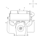
- FIG. 1 is a diagram schematically showing an example of the configuration of an engine to which a misfire detection device for a multi-cylinder engine according to an embodiment of the invention is applied;
- FIG. 1B is a side view of the engine of FIG. 1A;
- FIG. Rear view of the engine of FIG. 1A 1 is a block diagram schematically showing an example of a configuration of a main part of a misfire detection device for a multi-cylinder engine according to an embodiment of the present invention;
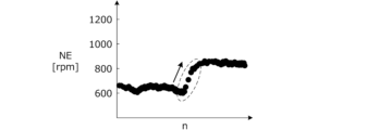
- FIG. FIG. 1B is a diagram for explaining the change characteristic of the rotation speed during the engine starting period when normal combustion is performed in all cylinders of FIG. 1A;
- FIG. 1B is a diagram for explaining the change characteristic of the rotation speed during the engine starting period when a misfire occurs in one of the cylinders in FIG. 1A;
- FIG. 1B is a diagram for explaining the change characteristic of the rotation speed during the engine starting period when a misfire occurs in the other cylinder of FIG. 1A;
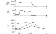
- FIG. 1B is a time chart for explaining a change characteristic of exhaust temperature when a misfire occurs in one cylinder during normal operation of the engine of FIG. 1A;
- FIG. FIG. 5 is a time chart for explaining change characteristics of the exhaust gas temperature after operation is stopped when the throttle valve is fully closed at the time of operation stop in FIG. 4 ;
- 4 is a flow chart showing an example of a misfire detection process at engine start executed by the misfire detection device for a multi-cylinder engine according to the embodiment of the present invention
- 4 is a flowchart showing an example of a combustion stop process at engine start-up executed by the misfire detection device for a multi-cylinder engine according to the embodiment of the present invention
- 4 is a flowchart showing an example of misfire detection processing during normal operation executed by the misfire detection device for a multi-cylinder engine according to the embodiment of the present invention
- 4 is a flowchart showing another example of misfire detection processing during normal operation executed by the misfire detection device for a multi-cylinder engine according to the embodiment of the present invention
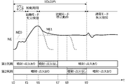
- 4 is a time chart showing an example of the operation of the misfire detection device for a multi-cylinder engine according to the embodiment of the present invention
- FIG. 1A A multi-cylinder engine misfire detection device according to an embodiment of the present invention is applied to an internal combustion engine having a plurality of cylinders.
- an example of application to a spark-ignited air-cooled 4-stroke V-type 2-cylinder engine, which is particularly popular as a small general-purpose engine, will be described.
- FIGS. 1A to 1C are diagrams schematically showing an example of the configuration of an engine 1 to which a misfire detection device for a multi-cylinder engine according to an embodiment of the invention is applied.
- the engine 1 has a first cylinder 2a and a second cylinder 2b.
- a piston (not shown) is slidably disposed inside each cylinder 2a, 2b, and a combustion chamber is formed between the inner wall of each cylinder 2a, 2b and the crown surface of the piston.
- the pistons of the cylinders 2a and 2b are connected to the crankshaft 3, which is the output shaft of the engine 1, via connecting rods (not shown). Reciprocating motion of the pistons along the inner walls of the cylinders 2a and 2b rotates the crankshaft 3, thereby rotating the engine 1 (output shaft).
- the crankshaft 3 is provided with a rotation sensor 3a such as a pulser coil that outputs a pulse signal each time the crankshaft 3 rotates by a predetermined angle ⁇ (for example, 15°).
- the rotation speed NE of the engine 1 can be calculated based on the pulse signal from the rotation sensor 3a.
- a pulse signal from the rotation sensor 3 a is input to an electronic control unit 10 ( FIG. 2 ) that controls the operation of the engine 1 .
- an intake passage 4 that takes in fresh air supplied to each cylinder 2a, 2b branches into intake passages 4a, 4b corresponding to each cylinder 2a, 2b.
- the intake passage 4 takes in fresh air from the outside via an air cleaner 13 (FIG. 1B) arranged in the upper part of the engine 1 between the cylinders 2a and 2b.
- Each cylinder 2a, 2b is communicated with each intake passage 4a, 4b via an intake port that is opened and closed by an intake valve (not shown), and each cylinder 2a is connected to each cylinder 2a through an exhaust port that is opened and closed by an exhaust valve (not shown).
- 2b communicate with each other.
- the operation of the intake and exhaust valves is controlled by an electronic control unit 10 (FIG. 2).
- a throttle valve 6 is interposed in the intake passage 4 on the upstream side of the branch point where the intake passages 4a and 4b are branched.
- the throttle valve 6 is composed of, for example, a butterfly valve, and the flow rate (amount of fresh air) supplied to each cylinder 2a, 2b is adjusted by the throttle valve 6.
- the throttle valve 6 is provided with a throttle valve actuator 6a for adjusting the opening degree of the throttle valve 6.
- the operation of the throttle valve actuator 6a is controlled by an electronic control unit 10 (FIG. 2).
- Injectors 7a and 7b are provided in the intake passages 4a and 4b near the intake ports of the cylinders 2a and 2b, respectively. Each injector 7a, 7b is driven by electrical energy to open and injects fuel of a predetermined pressure supplied from a fuel tank via a fuel pump (not shown), thereby injecting fuel into each cylinder 2a, 7b via an intake port. Fuel is supplied to the combustion chamber 2b. Spark plugs 8a and 8b are provided in the respective cylinders 2a and 2b so as to face the combustion chambers. Each spark plug 8a, 8b generates a spark by electrical energy, and ignites a mixture of fresh air and fuel in the combustion chamber of each cylinder 2a, 2b. The operation of each injector 7a, 7b and each spark plug 8a, 8b is controlled by an electronic control unit 10 (FIG. 2).
- exhaust gas discharged from each cylinder 2a, 2b is purified in the exhaust passage 5 downstream of the junction where the exhaust passages 5a, 5b join in the upper rear part of the engine 1.
- a catalyst device 9 is interposed. Exhaust gas purified by the catalyst device 9 is discharged to the outside through the muffler 15 .
- the catalyst device 9 uses a noble metal catalyst such as a three-way catalyst that oxidizes HC and CO contained in the exhaust gas and reduces NOx to purify the exhaust gas.
- a catalyst is carried on a carrier in a highly dispersed state by impregnation or the like in order to suppress the amount of precious metal used while ensuring purification performance. Sintering reduces the specific surface area and the number of active sites, and irreversibly lowers the purification performance.
- An exhaust gas temperature sensor 9a is provided in the exhaust passage 5 on the downstream side of the catalyst device 9 to detect the temperature (exhaust gas temperature) Tex of the exhaust gas. A signal from the exhaust temperature sensor 9a is input to the electronic control unit 10 (FIG. 2).
- the engine 1 is started in a misfire state in which one of the cylinders 2a, 2b misfires due to poor ignition, and the engine 1 continues to operate.
- the catalyst device 9 may be damaged. Therefore, in this embodiment, a misfire state of the engine 1 is detected immediately after starting, and the operation of the engine 1 is promptly stopped as necessary, so that the catalyst device 9 can be appropriately protected. It constitutes an engine misfire detection device.
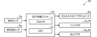
- FIG. 2 is a block diagram schematically showing an example of a main configuration of a multi-cylinder engine misfire detection device (hereinafter referred to as device) 20 according to an embodiment of the present invention.
- the device 20 is mainly composed of an electronic control unit 10.
- the electronic control unit 10 includes a computer having a processor 11 such as a CPU, a memory 12 such as ROM and RAM, and other peripheral circuits.
- the electronic control unit 10 is connected with a rotation sensor 3a, an exhaust temperature sensor 9a, a throttle valve actuator 6a, injectors 7a and 7b, and spark plugs 8a and 8b.
- the processor 11 of the electronic control unit 10 determines that one of the cylinders 2a and 2b is misfiring based on the rotation speed NE of the engine 1 detected by the rotation sensor 3a or the exhaust temperature Tex detected by the exhaust temperature sensor 9a. A misfire condition of the engine 1 is detected. When a misfire state of the engine 1 is detected, the operation of the throttle valve actuator 6a, the injectors 7a, 7b, and the spark plugs 8a, 8b is controlled so that the engine 1 stops operating as necessary.
- FIGS. 3A to 3C are diagrams for explaining the change characteristics of the rotation speed NE during the starting period of the engine 1.
- each time the rotation sensor 3a detects the n-th pulse signal shows an example of the instantaneous rotational speed NE of the engine 1 calculated in .
- 3A to 3C a case of detecting a misfire state of the engine 1 based on the instantaneous rotation speed NE of the engine 1 detected by the rotation sensor 3a during the starting period of the engine 1 will be described.
- a pulse signal detected by the rotation sensor 3a is generated each time the crankshaft 3 rotates by a predetermined angle ⁇ (for example, 15°). Therefore, for example, the instantaneous angular velocity ⁇ /ti [rad/s] of the crankshaft 3 is calculated based on the time interval ti between two pulses continuously detected by the rotation sensor 3a, and the instantaneous angular velocity of the engine 1 is calculated. can be converted to a simple rotational speed NE [rpm].
- the instantaneous rotational speed NE is calculated, and the previous value and the current value are compared to determine whether or not the rotational speed NE has increased. As shown in FIG. 3A, when the instantaneous rotational speed NE increases twice every two revolutions of the engine 1, it is determined that normal combustion is occurring in all the cylinders 2a and 2b. can be done.
- the detection of the misfire state based on the momentary rotation speed NE of the engine 1 is performed while the engine 1 is being started. That is, when the cranking of the engine 1 by the starter motor, the recoil starter, etc. is completed and the rotational speed NE begins to increase beyond a predetermined speed NE0 corresponding to complete explosion rotation, the rotation speed NE is started to increase to a predetermined speed NE1 corresponding to idling rotation. during the start-up period until convergence to
- the rotation of the engine 1 is unstable, and the change characteristic (fluctuation pattern) of the rotational speed NE changes according to the starting conditions such as the outside air temperature, the outside air pressure, and the temperature state of the engine 1 . Therefore, if a misfire state is detected based on the change characteristic of the rotation speed NE during the starting period of the engine 1, the misfire state may be erroneously detected or the normal cylinder or misfired cylinder may be erroneously estimated.
- the processor 11 of the electronic control unit 10 continuously determines the presence or absence of a misfire state every two revolutions of the engine 1 during the starting period, and determines that the misfire state has occurred a predetermined number of times (for example, once) or more during the starting period.
- a misfire condition of the engine 1 is detected when it is determined.
- the misfire state of the engine 1 can be reliably detected.
- Such a predetermined number of times may be two or more times, and may be changed according to the starting conditions. In this case, erroneous detection of a misfire state can be suppressed as necessary.
- the processor 11 of the electronic control unit 10 causes the injectors 7a, 7b and the spark plugs to stop fuel supply and ignition to one of the cylinders 2a, 2b estimated as normal cylinders. It controls the operations of 8a and 8b. If misfire detection and estimation of normal cylinders and misfiring cylinders are correct, fuel supply and ignition to normal cylinders are stopped, so that combustion is stopped in all cylinders 2a and 2b and the entire engine 1 is stopped. is protected.
- the processor 11 of the electronic control unit 10 causes the injectors 7a and 7b to resume fuel supply and ignition to the cylinders 2a and 2b that are estimated to be normal cylinders. and the operation of the spark plugs 8a and 8b. Further, the operation of the injectors 7a, 7b and the spark plugs 8a, 8b is controlled so as to stop fuel supply and ignition to the other cylinders 2a, 2b which are estimated to be misfiring cylinders.
- the misfire detection itself If the misfire detection itself is correct, the fuel supply and ignition of the normal cylinder, which is erroneously estimated as the misfiring cylinder, is stopped, so that the combustion is stopped in all the cylinders 2a and 2b, and the entire engine 1 is stopped. 9 is protected. On the other hand, if the misfire detection itself is erroneous, the operation of the entire engine 1 continues by continuing combustion in the normal cylinders in which fuel supply and ignition are restarted. In this case, the user's convenience is not impaired by stopping the operation of the engine 1 due to erroneous detection.
- the engine 1 After the engine 1 is started and starts operating in a normal temperature state that is not in a high temperature state such as immediately after the previous operation, it usually takes a certain amount of time (for example, several tens of minutes) is required (catalyst warm-up period). During the catalyst warm-up period, even if the engine 1 continues to operate in a misfired state, the catalyst temperature is low and even if unburned gas flows into the catalyst device 9, the oxidation reaction does not progress easily. It is difficult to detect the misfire state of the engine 1 based on the exhaust temperature Tex. By performing detection based on the rotation speed NE without depending on the exhaust temperature Tex, it is possible to detect a misfire state of the engine 1 early even during the start period, and appropriately protect the catalyst device 9 .
- a certain amount of time for example, several tens of minutes
- FIG. 4 is a time chart for explaining the change characteristics of the exhaust gas temperature Tex when a misfire occurs in one of the cylinders 2a, 2b during normal operation of the engine 1.
- FIG. 4 a case of detecting a misfire state of engine 1 based on exhaust temperature Tex detected by exhaust temperature sensor 9a during normal operation of engine 1 will be described.
- the processor 11 of the electronic control unit 10 detects that the exhaust temperature Tex of the engine 1 detected by the exhaust temperature sensor 9a exceeds the threshold value T0 during normal operation after the startup period of the engine 1 has passed, and if the state continues for a predetermined time ( At times t2 to t3), a misfire state of the engine 1 is detected.
- a misfire state of the engine 1 is detected when there is a high probability that one of the cylinders 2a, 2b misfires by monitoring an increase in the exhaust gas temperature Tex corresponding to an increase in the catalyst temperature Tcat due to the oxidation reaction of the unburned gas. be able to.
- the processor 11 controls the operations of the throttle valve actuator 6a, the injectors 7a, 7b, and the spark plugs 8a, 8b so that the engine 1 stops when a misfire condition of the engine 1 is detected based on the exhaust temperature Tex. (time t3).
- 5A and 5B are time charts for explaining the change characteristic of the exhaust gas temperature Tex after the engine 1 stops operating.
- FIG. 5A shows the temperature change when the throttle valve 6 is fully closed
- FIG. 5B indicates the temperature change when the throttle valve 6 is fully opened.
- the injectors 7a, 7b and spark plugs 8a, 8b are controlled to stop fuel supply and ignition to the cylinders 2a, 2b. immediately stops the operation of the engine 1 (time t3).
- the throttle valve 6 is further fully closed to immediately stop the supply of fresh air, thereby quickly stopping the oxidation reaction of the unburned gas and stopping the operation of the engine 1.
- Subsequent increases in catalyst temperature can be minimized. That is, as shown in FIG. 5B, it is possible to suppress the increase in the catalyst temperature after the operation of the engine 1 is stopped (increase in the exhaust temperature Tex: ⁇ T1 ⁇ T2).
- FIGS. 6 to 8B are flowcharts showing an example of processing executed by the processor 11 of the electronic control unit 10.
- FIG. 6 shows misfire detection processing at startup
- FIG. 7 shows combustion stop processing at startup
- FIGS. 8A and 8B show misfire detection processing during normal operation.
- the processes of FIGS. 6 to 8B are started when the electronic control unit 10 is activated, and are repeated at predetermined intervals. For example, it repeats every cycle of the engine 1 .
- step S1 it is determined whether or not the engine 1 is in normal operation after the startup period. If the result in step S1 is affirmative, the process ends. If the answer in step S1 is NO, the process proceeds to step S2. In step S2, it is determined whether or not the engine 1 has finished cranking and the rotational speed NE has exceeded a predetermined speed NE0 corresponding to the full explosion speed. If the result in step S2 is NO, it is determined that the engine 1 is being cranked, and the process ends. If the result in step S2 is affirmative, the process proceeds to step S3. In step S3, it is determined whether or not the rotation speed NE has decreased and started to converge to a predetermined speed NE1 corresponding to idle rotation.
- step S3 If the result in step S3 is negative, it is determined that it is in the starting period, and the process proceeds to steps S4 to S6.
- step S4 the misfire detection mode is switched to a starting mode that detects a misfire condition based on the instantaneous rotational speed NE during starting.
- step S5 it is determined whether or not the instantaneous rotation speed NE increases twice per two rotations of the engine 1, which corresponds to one cycle. If the result in step S5 is affirmative, the normal counter is incremented by "1" in step S6, and the process returns to step S3. If the result in step S5 is NO, the process returns to step S3 without incrementing the normal counter.
- step S7 it is determined whether or not the normal counter is "0". If the result in step S7 is affirmative, it is determined that the engine 1 is in a misfired state, the process proceeds to step S8, and a start mode stop operation (FIG. 7) is commanded. If the result in step S7 is NO, it is determined that the engine 1 is not in a misfire state, the process proceeds to step S9, and the misfire detection mode is a normal mode (Fig. 8A , FIG. 8B).
- step S10 it is determined whether or not the stopping operation of the starting mode has been commanded. If the answer in step S10 is negative, the process ends. If the result in step S10 is affirmative, the process proceeds to step S11. In step S11, the operations of the injectors 7a, 7b and the spark plugs 8a, 8b are controlled so as to stop fuel supply and ignition to one of the cylinders 2a, 2b estimated to be normal.
- step S12 it is determined whether or not the rotation speed NE is maintained at a predetermined speed NE1 corresponding to idle rotation. If the answer in step S12 is NO, the process ends. In this case, the rotational speed NE decreases and the operation of the engine 1 stops.
- step S12 determines whether or not a predetermined time has passed while the rotational speed NE is maintained at a predetermined speed NE1 corresponding to idling. If the answer in step S13 is NO, the process returns to step S12. If the result in step S13 is affirmative, it is determined that the misfire detection or the estimation of the normal cylinder/misfiring cylinder was erroneous, and the process proceeds to step S14.
- step S14 the operations of the injectors 7a, 7b and the spark plugs 8a, 8b are controlled so as to resume fuel supply and ignition to one of the cylinders 2a, 2b estimated as normal. Further, the operations of the injectors 7a, 7b and the spark plugs 8a, 8b are controlled so as to stop fuel supply and ignition to the other cylinders 2a, 2b which are estimated to be misfiring cylinders.
- step S15 it is determined whether or not the rotation speed NE is maintained at a predetermined speed NE1 corresponding to idle rotation. If the answer in step S15 is NO, the process ends. In this case, the rotational speed NE decreases and the operation of the engine 1 stops. If the result in step S15 is affirmative, the process proceeds to step S16. In step S16, it is determined whether or not a predetermined time has elapsed while the rotation speed NE is maintained at a predetermined speed NE1 corresponding to idle rotation. If the answer in step S16 is NO, the process returns to step S15. If the result in step S16 is affirmative, it is determined that the misfire detection itself was erroneous, and the process proceeds to step S17.
- step S17 the operations of the injectors 7a and 7b and the spark plugs 8a and 8b are controlled so as to resume fuel supply and ignition to the other cylinders 2a and 2b that are estimated to be misfiring cylinders.
- step S18 the misfire detection mode is switched to the normal mode (FIGS. 8A and 8B) in which the misfire state is detected based on the exhaust gas temperature Tex during normal operation.
- step S20 it is determined whether or not the engine 1 is in normal operation after the starting period. If the answer in step S20 is NO, the process ends. If the result in step S20 is affirmative, the process proceeds to step S21. In step S21, it is determined whether or not the exhaust temperature Tex exceeds the threshold value T0. If the answer in step S21 is NO, the process ends. If the result in step S21 is affirmative, the process proceeds to step S22. In step S22, it is determined whether or not a predetermined period of time has elapsed while the exhaust gas temperature Tex remains above the threshold value T0. If the answer in step S22 is negative, the process returns to step S21.
- step S23 the operations of the injectors 7a and 7b and the spark plugs 8a and 8b are controlled so that the fuel supply and ignition to the cylinders 2a and 2b are stopped and the operation of the engine 1 is immediately stopped. Further, the operation of the throttle valve actuator 6a is controlled so that the throttle valve 6 is fully closed and the supply of fresh air is immediately stopped.
- step S20 it is determined whether or not the engine 1 is in normal operation after the starting period. If the answer in step S20 is NO, the process ends. If the result in step S20 is affirmative, the process proceeds to step S24. In step S24, it is determined whether or not the rate of increase ⁇ Tex of the exhaust temperature Tex exceeds the threshold ⁇ T0. If the answer in step S24 is NO, the process ends. If the result in step S24 is affirmative, it is determined that the engine 1 is in a misfire state, and the process proceeds to step S23.
- step S23 the operations of the injectors 7a and 7b and the spark plugs 8a and 8b are controlled so that the fuel supply and ignition to the cylinders 2a and 2b are stopped and the operation of the engine 1 is immediately stopped. Further, the operation of the throttle valve actuator 6a is controlled so that the throttle valve 6 is fully closed and the supply of fresh air is immediately stopped.
- FIG. 9 is a time chart showing an example of the operation of the multi-cylinder engine misfire detection device according to the embodiment of the present invention.
- cranking of the engine 1 is started at time t0, and when the rotation speed NE exceeds a predetermined speed NE0 corresponding to complete explosion rotation at time t5, misfire detection in the start mode is started (FIG. 6). steps S1 to S6).
- the misfire state of the engine 1 is detected based on the rotation speed NE regardless of the exhaust temperature Tex, so the misfire state of the engine 1 can be detected immediately after the end of cranking.
- Step S3, S7 and S8 in FIG. 6 When a misfire state of the engine 1 is detected during the starting period until the rotational speed NE decreases at time t6 and begins to converge to a predetermined speed NE1 corresponding to idling, the stop operation of the starting mode is started at time t6. (Steps S3, S7 and S8 in FIG. 6).
- Steps S10 and S11 in FIG. 7 When the stopping operation of the starting mode is started at time t6, first, fuel supply and ignition to the first cylinder 2a, which is estimated to be a normal cylinder, are stopped (steps S10 and S11 in FIG. 7).
- the rotation speed NE decreases as indicated by the dashed line, and the engine 1 stops, thereby protecting the catalyst device 9 ("NO" in step S12 in FIG. 7). ).
- the rotation speed NE is maintained at the predetermined speed NE1 corresponding to the idle rotation ("YES" in steps S12 and S13 of FIG. 7).
- step S14 fuel supply and ignition to the second cylinder 2b, which is estimated to be the misfiring cylinder, are stopped (step S14 in FIG. 7).
- the rotational speed NE decreases as indicated by the dashed line, and the engine 1 stops, thereby protecting the catalyst device 9 ("NO" in step S15 of FIG. 7).
- the rotational speed NE is maintained at the predetermined speed NE1 corresponding to idling ("YES" in steps S15 and S16 of FIG. 7).
- the start mode when a misfire state of the engine 1 is detected during the start period from time t5 to t6, a stop operation for stopping combustion is sequentially performed for each cylinder 2a, 2b from time t6 to t9.
- the operation of the engine 1 can be continued even if is erroneously detected. Therefore, the user's convenience is not impaired by stopping the operation of the engine 1 due to erroneous detection.
- a starting mode is performed within a short period of time, for example, within 10 seconds from the start of cranking of the engine 1, the user's convenience is not impaired.
- the device 20 is an engine 1 having a plurality of cylinders 2a and 2b and a catalyst device 9 for purifying the exhaust gas from the plurality of cylinders 2a and 2b.
- a misfire condition is detected (FIGS. 1A-1C).
- the device 20 comprises a rotation sensor 3a for detecting the rotational speed NE of the engine 1, a processor 11 and a memory 12 connected to the processor 11, and an electronic control unit 10 configured to control the operation of the engine 1. (FIGS. 1A, 2).
- Processor 11 detects a misfire state of engine 1 based on rotation speed NE of engine 1 detected by rotation sensor 3a (FIGS. 3A to 3C and FIG. 6). Since the detection is based on the rotation speed NE of the engine 1, the misfire state of the engine 1 can be detected immediately after cranking with a simple configuration.
- the device 20 further includes an exhaust temperature sensor 9a that detects the exhaust temperature Tex of the engine 1 (Figs. 1A, 1B, 2).
- the processor 11 detects a misfire state of the engine 1 based on the rotation speed NE of the engine 1 detected by the rotation sensor 3a or the exhaust temperature Tex detected by the exhaust temperature sensor 9a (FIGS. 3A to 4, 6, 8A, 8B).
- the misfired state of the engine 1 can be detected earlier, and when detected based on the exhaust temperature Tex, the misfired state of the engine 1 can be detected more reliably. can do.
- the exhaust temperature sensor 9a detects the exhaust temperature Tex after passing through the catalyst device 9 (FIGS. 1A and 1B). If the engine 1 continues to operate with one of the cylinders 2a and 2b misfiring, the catalyst temperature rises due to the oxidation reaction of the unburned gas that flows into the catalyst device 9 through the misfiring cylinder. By detecting the exhaust gas temperature Tex after passing through the catalyst device 9, the increase in the catalyst temperature due to the oxidation reaction of the unburned gas is monitored, and the engine 1 misfire condition can be detected.
- the engine 1 has a throttle valve 6 for adjusting the amount of fresh air supplied to the multiple cylinders 2a, 2b (Fig. 1A).
- the processor 11 detects a misfire state of the engine 1 based on the exhaust temperature Tex detected by the exhaust temperature sensor 9a ( 4, 6, 8A, 8B).
- the processor 11 controls the operation of the throttle valve 6 so that the engine 1 stops when the misfire state of the engine 1 is detected based on the exhaust temperature Tex detected by the exhaust temperature sensor 9a (FIGS. 4 and 5A). ).
- a misfire state of the engine 1 is detected based on the exhaust temperature Tex and there is a high probability that one of the cylinders 2a and 2b is misfiring, the operation of the engine 1 is immediately stopped to prevent damage to the catalytic device 9. can be prevented. Also, by closing the throttle valve 6 and immediately stopping the supply of fresh air, the oxidation reaction of the unburned gas can be quickly stopped, and the rise in the catalyst temperature can be minimized.
- the processor 11 detects a misfire state of the engine 1 when the state in which the exhaust temperature Tex detected by the exhaust temperature sensor 9a exceeds the threshold T0 continues for a predetermined time after the start period has elapsed (FIG. 8A). As a result, the misfire state of the engine 1 can be detected with high accuracy.
- the processor 11 detects a misfire state of the engine 1 when the rate of increase ⁇ Tex of the exhaust temperature Tex detected by the exhaust temperature sensor 9a exceeds the threshold ⁇ T0 after the start period has elapsed (FIG. 8B). As a result, the misfire state of the engine 1 can be detected with high accuracy.
- the processor 11 detects a misfire state of the engine 1 based on the rotation speed NE of the engine 1 detected by the rotation sensor 3a during the starting period in which the rotation speed NE of the engine 1 increases after the cranking of the engine 1 is finished. Detect (FIGS. 3A-3C, FIG. 6).
- a normal starting period of the engine 1 such as starting from a normal temperature state
- the catalyst temperature is lower than the normal operating temperature range, and even if unburned gas flows into the catalyst device 9, the oxidation reaction does not proceed easily. It is difficult to detect the misfire state of the engine 1 based on the temperature Tex.
- a misfire state of the engine 1 can be detected even during such a starting period by detecting based on the rotation speed NE without depending on the exhaust temperature Tex.
- the engine 1 is a four-stroke engine that makes two revolutions per cycle.
- the processor 11 detects a misfire state of the engine 1 based on the change characteristic of the rotation speed NE of the engine 1 detected by the rotation sensor 3a every two rotations of the engine 1 (FIGS. 3A to 3C, FIG. 6). Normal combustion in all cylinders 2a and 2b is determined by determining whether or not the rotational speed NE of the engine 1 rises twice corresponding to the number of cylinders per two revolutions corresponding to one cycle of the engine 1. is being performed or one of the cylinders is misfiring.
- the engine 1 has injectors 7a, 7b that supply fuel to the plurality of cylinders 2a, 2b, respectively (Fig. 1A).
- the processor 11 controls the operation of the injectors 7a and 7b so that the engine 1 stops when a misfire state of the engine 1 is detected based on the rotation speed NE of the engine 1 detected by the rotation sensor 3a (FIG. 7). ). For example, by estimating normal cylinders and misfiring cylinders based on the change characteristic (fluctuation pattern) of the rotation speed NE of the engine 1, and controlling the operation of the injectors 7a and 7b so as to stop fuel supply to the normal cylinders.
- the engine 1 can be stopped and the catalyst device 9 can be protected. In this case, even if the misfire state is erroneously detected, the operation of the engine 1 can be continued as it is, so the user's convenience is not impaired.
- the engine 1 is a V-type 2-cylinder engine that is popular as a small general-purpose engine (FIGS. 1A to 1C).
- a misfire state of the engine 1 at an early stage and appropriately protect the catalyst device 9 even with a simple configuration such as a small general-purpose engine.
- the device 20 is applied to the spark ignition type air-cooled 4-stroke V-type 2-cylinder engine 1
- the engine having a plurality of cylinders and a catalyst device is not limited to this.
- Compression ignition type, water-cooled type, 2-stroke, horizontally opposed type, in-line type, 3-cylinder or more engine can also detect a misfire state where some cylinders misfire based on rotation fluctuation during one cycle.
- can. 1B and 1C illustrate the horizontal type (horizontal shaft type) engine 1 that takes out power in the horizontal direction, but it may be a vertical type (vertical shaft type) that takes out power in the vertical direction.
- misfire state of the engine 1 when the exhaust temperature Tex continues to exceed the threshold value T0 in FIG. 8A has been described. Further, the example of detecting the misfire state of the engine 1 when the rate of increase ⁇ Tex of the exhaust temperature Tex exceeds the threshold ⁇ T0 has been described with reference to FIG. 8B and the like.
- detection of engine misfire based on exhaust gas temperature is not limited to this.
- the misfire state of the engine 1 may be detected when the exhaust temperature Tex continues to exceed the threshold T0 and the rate of increase ⁇ Tex of the exhaust temperature Tex exceeds the threshold ⁇ T0.
- the present invention has been described above as the misfire detection device 20 for a multi-cylinder engine, the present invention has a plurality of cylinders 2a and 2b and a catalyst device 9 for purifying exhaust gas from the plurality of cylinders 2a and 2b. It can also be used as a misfire detection method for a multi-cylinder engine for detecting a misfire state in which one of the plurality of cylinders 2a and 2b in the engine 1 misfires. That is, the misfire detection method for a multi-cylinder engine includes detecting a misfire state of the engine 1 based on the rotational speed NE of the engine 1 (step S5 in FIG. 6).
Landscapes
- Engineering & Computer Science (AREA)
- Chemical & Material Sciences (AREA)
- Combustion & Propulsion (AREA)
- Mechanical Engineering (AREA)
- General Engineering & Computer Science (AREA)
- Combined Controls Of Internal Combustion Engines (AREA)
- Electrical Control Of Air Or Fuel Supplied To Internal-Combustion Engine (AREA)
Abstract
Description
図3A~図3Cは、エンジン1の始動期間における回転速度NEの変化特性について説明するための図であり、エンジン1が2回転する間、回転センサ3aによりn番目のパルス信号が検出されるごとに算出されるエンジン1の瞬間的な回転速度NEの一例を示す。図3A~図3Cを参照して、エンジン1の始動期間中に回転センサ3aにより検出されるエンジン1の瞬間的な回転速度NEに基づいてエンジン1の失火状態を検知する場合について説明する。
エンジン1の失火状態が検知されると、電子制御ユニット10のプロセッサ11は、正常気筒として推定された一方の気筒2a,2bへの燃料供給および点火を停止するようにインジェクタ7a,7bおよび点火プラグ8a,8bの動作を制御する。失火検知および正常気筒・失火気筒の推定が正しければ、正常気筒の燃料供給および点火が停止されることで、すべての気筒2a,2bで燃焼が停止してエンジン1全体が停止し、触媒装置9が保護される。
図4は、エンジン1の通常運転中に一方の気筒2a,2bで失火が発生した場合の、排気温度Texの変化特性について説明するためのタイムチャートである。図4を参照して、エンジン1の通常運転中に排気温センサ9aにより検出される排気温度Texに基づいてエンジン1の失火状態を検知する場合について説明する。
プロセッサ11は、排気温度Texに基づいてエンジン1の失火状態が検知されると、エンジン1が停止するようにスロットルバルブ・アクチュエータ6a、インジェクタ7a,7b、および点火プラグ8a,8bの動作を制御する(時刻t3)。図5Aおよび図5Bは、エンジン1の運転停止後の排気温度Texの変化特性について説明するためのタイムチャートであり、図5Aは、スロットルバルブ6を全閉した場合の温度変化を示し、図5Bは、スロットルバルブ6を全開した場合の温度変化を示す。
(1)装置20は、複数の気筒2a,2bと、複数の気筒2a,2bからの排気ガスを浄化する触媒装置9とを有するエンジン1における複数の気筒2a,2bのいずれかが失火している失火状態を検知する(図1A~図1C)。装置20は、エンジン1の回転速度NEを検出する回転センサ3aと、プロセッサ11とプロセッサ11に接続されたメモリ12とを有し、エンジン1の動作を制御するように構成された電子制御ユニット10とを備える(図1A、図2)。プロセッサ11は、回転センサ3aにより検出されたエンジン1の回転速度NEに基づいてエンジン1の失火状態を検知する(図3A~図3C、図6)。エンジン1の回転速度NEに基づいて検知するため、簡易な構成でクランキング直後からエンジン1の失火状態を検知することができる。
Claims (11)
- 複数の気筒と、前記複数の気筒からの排気ガスを浄化する触媒装置と、を有するエンジンにおける前記複数の気筒のいずれかが失火している失火状態を検知する多気筒エンジンの失火検知装置であって、
前記エンジンの回転速度を検出する回転センサと、
プロセッサと該プロセッサに接続されたメモリとを有し、前記エンジンの動作を制御するように構成された電子制御ユニットと、を備え、
前記プロセッサは、前記回転センサにより検出された前記エンジンの回転速度に基づいて前記エンジンの失火状態を検知することを特徴とする多気筒エンジンの失火検知装置。 - 請求項1に記載の多気筒エンジンの失火検知装置において、
前記エンジンの排気ガスの温度を検出する排気温センサをさらに備え、
前記プロセッサは、前記回転センサにより検出された前記エンジンの回転速度または前記排気温センサにより検出された前記エンジンの排気ガスの温度に基づいて前記エンジンの失火状態を検知することを特徴とする多気筒エンジンの失火検知装置。 - 請求項2に記載の多気筒エンジンの失火検知装置において、
前記排気温センサは、前記触媒装置を通過した後の前記エンジンの排気ガスの温度を検出することを特徴とする多気筒エンジンの失火検知装置。 - 請求項2または3に記載の多気筒エンジンの失火検知装置において、
前記エンジンは、前記複数の気筒に供給される新気量を調整するスロットルバルブを有し、
前記プロセッサは、
前記エンジンのクランキング終了後、前記エンジンの回転速度が上昇する始動期間の経過後、前記排気温センサにより検出された前記エンジンの排気ガスの温度に基づいて前記エンジンの失火状態を検知し、
前記排気温センサにより検出された前記エンジンの排気ガスの温度に基づいて前記エンジンの失火状態が検知されると、前記エンジンが停止するように前記スロットルバルブの動作を制御することを特徴とする多気筒エンジンの失火検知装置。 - 請求項4に記載の多気筒エンジンの失火検知装置において、
前記プロセッサは、前記始動期間の経過後、前記排気温センサにより検出された前記エンジンの排気ガスの温度が閾値を超えた状態が所定時間継続すると前記エンジンの失火状態を検知することを特徴とする多気筒エンジンの失火検知装置。 - 請求項4に記載の多気筒エンジンの失火検知装置において、
前記プロセッサは、前記始動期間の経過後、前記排気温センサにより検出された前記エンジンの排気ガスの温度の上昇速度が閾値を超えると前記エンジンの失火状態を検知することを特徴とする多気筒エンジンの失火検知装置。 - 請求項1~6のいずれか1項に記載の多気筒エンジンの失火検知装置において、
前記プロセッサは、前記エンジンのクランキング終了後、前記エンジンの回転速度が上昇する始動期間に、前記回転センサにより検出された前記エンジンの回転速度に基づいて前記エンジンの失火状態を検知することを特徴とする多気筒エンジンの失火検知装置。 - 請求項7に記載の多気筒エンジンの失火検知装置において、
前記エンジンは、1サイクルあたり2回転する4ストロークエンジンであり、
前記プロセッサは、前記エンジンの2回転ごとに、前記回転センサにより検出された前記エンジンの回転速度の変化に基づいて前記エンジンの失火状態を検知することを特徴とする多気筒エンジンの失火検知装置。 - 請求項1~8のいずれか1項に記載の多気筒エンジンの失火検知装置において、
前記エンジンは、前記複数の気筒のそれぞれに燃料を供給するインジェクタを有し、
前記プロセッサは、前記回転センサにより検出された前記エンジンの回転速度に基づいて前記エンジンの失火状態が検知されると、前記エンジンが停止するように前記インジェクタの動作を制御することを特徴とする多気筒エンジンの失火検知装置。 - 請求項1~9のいずれか1項に記載の多気筒エンジンの失火検知装置において、
前記エンジンは、V型2気筒エンジンであることを特徴とする多気筒エンジンの失火検知装置。 - 複数の気筒と、前記複数の気筒からの排気ガスを浄化する触媒装置と、を有するエンジンにおける前記複数の気筒のいずれかが失火している失火状態を検知する多気筒エンジンの失火検知方法であって、
前記エンジンの回転速度に基づいて前記エンジンの失火状態を検知することを含むことを特徴とする多気筒エンジンの失火検知方法。
Priority Applications (3)
| Application Number | Priority Date | Filing Date | Title |
|---|---|---|---|
| PCT/JP2021/027854 WO2023007604A1 (ja) | 2021-07-28 | 2021-07-28 | 多気筒エンジンの失火検知装置および失火検知方法 |
| US18/291,911 US12378926B2 (en) | 2021-07-28 | 2021-07-28 | Misfire detection apparatus and misfire detection method for multi-cylinder engine |
| CN202180100826.3A CN117693624A (zh) | 2021-07-28 | 2021-07-28 | 多缸发动机的失火检测装置和失火检测方法 |
Applications Claiming Priority (1)
| Application Number | Priority Date | Filing Date | Title |
|---|---|---|---|
| PCT/JP2021/027854 WO2023007604A1 (ja) | 2021-07-28 | 2021-07-28 | 多気筒エンジンの失火検知装置および失火検知方法 |
Publications (1)
| Publication Number | Publication Date |
|---|---|
| WO2023007604A1 true WO2023007604A1 (ja) | 2023-02-02 |
Family
ID=85086447
Family Applications (1)
| Application Number | Title | Priority Date | Filing Date |
|---|---|---|---|
| PCT/JP2021/027854 Ceased WO2023007604A1 (ja) | 2021-07-28 | 2021-07-28 | 多気筒エンジンの失火検知装置および失火検知方法 |
Country Status (3)
| Country | Link |
|---|---|
| US (1) | US12378926B2 (ja) |
| CN (1) | CN117693624A (ja) |
| WO (1) | WO2023007604A1 (ja) |
Citations (9)
| Publication number | Priority date | Publication date | Assignee | Title |
|---|---|---|---|---|
| JPS62228128A (ja) * | 1986-03-29 | 1987-10-07 | Mitsubishi Motors Corp | 多気筒エンジンの失火気筒判別装置 |
| JPH03286168A (ja) * | 1990-04-02 | 1991-12-17 | Mitsubishi Electric Corp | エンジン用故障診断装置 |
| JPH09151723A (ja) * | 1995-11-28 | 1997-06-10 | Tokyo Gas Co Ltd | ガスエンジンの運転制御方法及び装置 |
| JP2000291485A (ja) * | 1999-04-06 | 2000-10-17 | Fuji Heavy Ind Ltd | エンジンの失火検知装置 |
| JP2010144619A (ja) * | 2008-12-18 | 2010-07-01 | Fuji Heavy Ind Ltd | エンジンの始動制御装置 |
| JP2013155672A (ja) * | 2012-01-30 | 2013-08-15 | Mitsubishi Electric Corp | 汎用エンジン制御装置 |
| JP2015059485A (ja) * | 2013-09-18 | 2015-03-30 | 三菱電機株式会社 | 内燃機関の失火検出装置および失火検出方法 |
| JP2019120187A (ja) * | 2018-01-04 | 2019-07-22 | トヨタ自動車株式会社 | 内燃機関の失火検出装置 |
| JP2020063710A (ja) * | 2018-10-18 | 2020-04-23 | 株式会社ケーヒン | 内燃機関の失火判定装置 |
Family Cites Families (6)
| Publication number | Priority date | Publication date | Assignee | Title |
|---|---|---|---|---|
| JPH06280671A (ja) * | 1993-03-26 | 1994-10-04 | Honda Motor Co Ltd | 内燃機関の燃焼状態判定装置及び燃焼状態制御装置 |
| JP2013209951A (ja) | 2012-03-30 | 2013-10-10 | Panasonic Corp | 原動機及びガスヒートポンプエアコン |
| JP6068234B2 (ja) * | 2013-03-29 | 2017-01-25 | 本田技研工業株式会社 | エンジン制御装置 |
| US10060382B2 (en) * | 2015-12-09 | 2018-08-28 | Ford Global Technologies, Llc | Method and system for pre-ignition control |
| JP7147694B2 (ja) * | 2019-06-18 | 2022-10-05 | トヨタ自動車株式会社 | ハイブリッド車両の制御装置 |
| JP7370047B2 (ja) * | 2019-10-29 | 2023-10-27 | 株式会社ニッキ | エンジンの失火診断検出方法 |
-
2021
- 2021-07-28 WO PCT/JP2021/027854 patent/WO2023007604A1/ja not_active Ceased
- 2021-07-28 CN CN202180100826.3A patent/CN117693624A/zh active Pending
- 2021-07-28 US US18/291,911 patent/US12378926B2/en active Active
Patent Citations (9)
| Publication number | Priority date | Publication date | Assignee | Title |
|---|---|---|---|---|
| JPS62228128A (ja) * | 1986-03-29 | 1987-10-07 | Mitsubishi Motors Corp | 多気筒エンジンの失火気筒判別装置 |
| JPH03286168A (ja) * | 1990-04-02 | 1991-12-17 | Mitsubishi Electric Corp | エンジン用故障診断装置 |
| JPH09151723A (ja) * | 1995-11-28 | 1997-06-10 | Tokyo Gas Co Ltd | ガスエンジンの運転制御方法及び装置 |
| JP2000291485A (ja) * | 1999-04-06 | 2000-10-17 | Fuji Heavy Ind Ltd | エンジンの失火検知装置 |
| JP2010144619A (ja) * | 2008-12-18 | 2010-07-01 | Fuji Heavy Ind Ltd | エンジンの始動制御装置 |
| JP2013155672A (ja) * | 2012-01-30 | 2013-08-15 | Mitsubishi Electric Corp | 汎用エンジン制御装置 |
| JP2015059485A (ja) * | 2013-09-18 | 2015-03-30 | 三菱電機株式会社 | 内燃機関の失火検出装置および失火検出方法 |
| JP2019120187A (ja) * | 2018-01-04 | 2019-07-22 | トヨタ自動車株式会社 | 内燃機関の失火検出装置 |
| JP2020063710A (ja) * | 2018-10-18 | 2020-04-23 | 株式会社ケーヒン | 内燃機関の失火判定装置 |
Also Published As
| Publication number | Publication date |
|---|---|
| CN117693624A (zh) | 2024-03-12 |
| US20240384691A1 (en) | 2024-11-21 |
| US12378926B2 (en) | 2025-08-05 |
Similar Documents
| Publication | Publication Date | Title |
|---|---|---|
| JP5742682B2 (ja) | 内燃機関の始動制御装置 | |
| US20110283688A1 (en) | Operation control device and operation control method for multi-cylinder internal combustion engine | |
| JP5821566B2 (ja) | 内燃機関の失火異常検出装置 | |
| JP3931820B2 (ja) | 内燃機関および内燃機関の制御方法 | |
| JP2013130092A (ja) | 内燃機関の始動時気筒判別方法 | |
| WO2023007604A1 (ja) | 多気筒エンジンの失火検知装置および失火検知方法 | |
| JP2010216322A (ja) | 内燃機関の始動時気筒判別方法 | |
| JP2008248740A (ja) | 内燃機関の始動時気筒判別方法 | |
| JPH10252532A (ja) | 内燃機関の燃料カット制御装置 | |
| JP2008267306A (ja) | 燃料供給量制御装置および船舶推進装置 | |
| JP2014214676A (ja) | 内燃機関の制御装置 | |
| JP5447236B2 (ja) | 多気筒内燃機関の燃料噴射制御装置 | |
| JP3890828B2 (ja) | 内燃機関の燃料カット制御装置 | |
| JP2008280865A (ja) | 内燃機関の始動制御装置 | |
| JP4466498B2 (ja) | 内燃機関の点火時期制御装置 | |
| JP5482515B2 (ja) | 多気筒内燃機関の制御装置 | |
| JPH09112395A (ja) | エンジンの点火制御装置 | |
| JP2007040219A (ja) | 内燃機関の制御装置 | |
| JPH1150885A (ja) | 内燃機関の燃料カット制御装置 | |
| JPH1162664A (ja) | 内燃機関の燃料カット制御装置 | |
| JPH1061482A (ja) | 筒内噴射型内燃機関のノック制御装置 | |
| JP2007192081A (ja) | 内燃機関の制御装置 | |
| JP4232373B2 (ja) | エンジンの排気浄化装置 | |
| JP6119415B2 (ja) | 可変動弁機構の弁開閉時期検出装置、及び可変動弁機構の制御装置 | |
| JP2018112112A (ja) | エンジン装置 |
Legal Events
| Date | Code | Title | Description |
|---|---|---|---|
| 121 | Ep: the epo has been informed by wipo that ep was designated in this application |
Ref document number: 21951812 Country of ref document: EP Kind code of ref document: A1 |
|
| DPE1 | Request for preliminary examination filed after expiration of 19th month from priority date (pct application filed from 20040101) | ||
| WWE | Wipo information: entry into national phase |
Ref document number: 202180100826.3 Country of ref document: CN |
|
| WWE | Wipo information: entry into national phase |
Ref document number: 18291911 Country of ref document: US |
|
| NENP | Non-entry into the national phase |
Ref country code: DE |
|
| 122 | Ep: pct application non-entry in european phase |
Ref document number: 21951812 Country of ref document: EP Kind code of ref document: A1 |
|
| NENP | Non-entry into the national phase |
Ref country code: JP |
|
| WWG | Wipo information: grant in national office |
Ref document number: 18291911 Country of ref document: US |