WO2023007528A1 - ハイブリッド車両における内燃機関の始動・停止制御方法および装置 - Google Patents
ハイブリッド車両における内燃機関の始動・停止制御方法および装置 Download PDFInfo
- Publication number
- WO2023007528A1 WO2023007528A1 PCT/JP2021/027467 JP2021027467W WO2023007528A1 WO 2023007528 A1 WO2023007528 A1 WO 2023007528A1 JP 2021027467 W JP2021027467 W JP 2021027467W WO 2023007528 A1 WO2023007528 A1 WO 2023007528A1
- Authority
- WO
- WIPO (PCT)
- Prior art keywords
- combustion engine
- internal combustion
- temperature
- hybrid vehicle
- stop control
- Prior art date
- Legal status (The legal status is an assumption and is not a legal conclusion. Google has not performed a legal analysis and makes no representation as to the accuracy of the status listed.)
- Ceased
Links
Images


Classifications
-
- B—PERFORMING OPERATIONS; TRANSPORTING
- B60—VEHICLES IN GENERAL
- B60W—CONJOINT CONTROL OF VEHICLE SUB-UNITS OF DIFFERENT TYPE OR DIFFERENT FUNCTION; CONTROL SYSTEMS SPECIALLY ADAPTED FOR HYBRID VEHICLES; ROAD VEHICLE DRIVE CONTROL SYSTEMS FOR PURPOSES NOT RELATED TO THE CONTROL OF A PARTICULAR SUB-UNIT
- B60W20/00—Control systems specially adapted for hybrid vehicles
- B60W20/10—Controlling the power contribution of each of the prime movers to meet required power demand
- B60W20/15—Control strategies specially adapted for achieving a particular effect
- B60W20/16—Control strategies specially adapted for achieving a particular effect for reducing engine exhaust emissions
-
- B—PERFORMING OPERATIONS; TRANSPORTING
- B60—VEHICLES IN GENERAL
- B60W—CONJOINT CONTROL OF VEHICLE SUB-UNITS OF DIFFERENT TYPE OR DIFFERENT FUNCTION; CONTROL SYSTEMS SPECIALLY ADAPTED FOR HYBRID VEHICLES; ROAD VEHICLE DRIVE CONTROL SYSTEMS FOR PURPOSES NOT RELATED TO THE CONTROL OF A PARTICULAR SUB-UNIT
- B60W20/00—Control systems specially adapted for hybrid vehicles
- B60W20/40—Controlling the engagement or disengagement of prime movers, e.g. for transition between prime movers
-
- B—PERFORMING OPERATIONS; TRANSPORTING
- B60—VEHICLES IN GENERAL
- B60K—ARRANGEMENT OR MOUNTING OF PROPULSION UNITS OR OF TRANSMISSIONS IN VEHICLES; ARRANGEMENT OR MOUNTING OF PLURAL DIVERSE PRIME-MOVERS IN VEHICLES; AUXILIARY DRIVES FOR VEHICLES; INSTRUMENTATION OR DASHBOARDS FOR VEHICLES; ARRANGEMENTS IN CONNECTION WITH COOLING, AIR INTAKE, GAS EXHAUST OR FUEL SUPPLY OF PROPULSION UNITS IN VEHICLES
- B60K6/00—Arrangement or mounting of plural diverse prime-movers for mutual or common propulsion, e.g. hybrid propulsion systems comprising electric motors and internal combustion engines
- B60K6/20—Arrangement or mounting of plural diverse prime-movers for mutual or common propulsion, e.g. hybrid propulsion systems comprising electric motors and internal combustion engines the prime-movers consisting of electric motors and internal combustion engines, e.g. HEVs
- B60K6/42—Arrangement or mounting of plural diverse prime-movers for mutual or common propulsion, e.g. hybrid propulsion systems comprising electric motors and internal combustion engines the prime-movers consisting of electric motors and internal combustion engines, e.g. HEVs characterised by the architecture of the hybrid electric vehicle
- B60K6/46—Series type
-
- B—PERFORMING OPERATIONS; TRANSPORTING
- B60—VEHICLES IN GENERAL
- B60W—CONJOINT CONTROL OF VEHICLE SUB-UNITS OF DIFFERENT TYPE OR DIFFERENT FUNCTION; CONTROL SYSTEMS SPECIALLY ADAPTED FOR HYBRID VEHICLES; ROAD VEHICLE DRIVE CONTROL SYSTEMS FOR PURPOSES NOT RELATED TO THE CONTROL OF A PARTICULAR SUB-UNIT
- B60W10/00—Conjoint control of vehicle sub-units of different type or different function
- B60W10/04—Conjoint control of vehicle sub-units of different type or different function including control of propulsion units
- B60W10/06—Conjoint control of vehicle sub-units of different type or different function including control of propulsion units including control of combustion engines
-
- B—PERFORMING OPERATIONS; TRANSPORTING
- B60—VEHICLES IN GENERAL
- B60W—CONJOINT CONTROL OF VEHICLE SUB-UNITS OF DIFFERENT TYPE OR DIFFERENT FUNCTION; CONTROL SYSTEMS SPECIALLY ADAPTED FOR HYBRID VEHICLES; ROAD VEHICLE DRIVE CONTROL SYSTEMS FOR PURPOSES NOT RELATED TO THE CONTROL OF A PARTICULAR SUB-UNIT
- B60W10/00—Conjoint control of vehicle sub-units of different type or different function
- B60W10/04—Conjoint control of vehicle sub-units of different type or different function including control of propulsion units
- B60W10/08—Conjoint control of vehicle sub-units of different type or different function including control of propulsion units including control of electric propulsion units, e.g. motors or generators
-
- B—PERFORMING OPERATIONS; TRANSPORTING
- B60—VEHICLES IN GENERAL
- B60W—CONJOINT CONTROL OF VEHICLE SUB-UNITS OF DIFFERENT TYPE OR DIFFERENT FUNCTION; CONTROL SYSTEMS SPECIALLY ADAPTED FOR HYBRID VEHICLES; ROAD VEHICLE DRIVE CONTROL SYSTEMS FOR PURPOSES NOT RELATED TO THE CONTROL OF A PARTICULAR SUB-UNIT
- B60W10/00—Conjoint control of vehicle sub-units of different type or different function
- B60W10/24—Conjoint control of vehicle sub-units of different type or different function including control of energy storage means
- B60W10/26—Conjoint control of vehicle sub-units of different type or different function including control of energy storage means for electrical energy, e.g. batteries or capacitors
-
- B—PERFORMING OPERATIONS; TRANSPORTING
- B60—VEHICLES IN GENERAL
- B60W—CONJOINT CONTROL OF VEHICLE SUB-UNITS OF DIFFERENT TYPE OR DIFFERENT FUNCTION; CONTROL SYSTEMS SPECIALLY ADAPTED FOR HYBRID VEHICLES; ROAD VEHICLE DRIVE CONTROL SYSTEMS FOR PURPOSES NOT RELATED TO THE CONTROL OF A PARTICULAR SUB-UNIT
- B60W20/00—Control systems specially adapted for hybrid vehicles
- B60W20/10—Controlling the power contribution of each of the prime movers to meet required power demand
- B60W20/11—Controlling the power contribution of each of the prime movers to meet required power demand using model predictive control [MPC] strategies, i.e. control methods based on models predicting performance
-
- B—PERFORMING OPERATIONS; TRANSPORTING
- B60—VEHICLES IN GENERAL
- B60W—CONJOINT CONTROL OF VEHICLE SUB-UNITS OF DIFFERENT TYPE OR DIFFERENT FUNCTION; CONTROL SYSTEMS SPECIALLY ADAPTED FOR HYBRID VEHICLES; ROAD VEHICLE DRIVE CONTROL SYSTEMS FOR PURPOSES NOT RELATED TO THE CONTROL OF A PARTICULAR SUB-UNIT
- B60W20/00—Control systems specially adapted for hybrid vehicles
- B60W20/10—Controlling the power contribution of each of the prime movers to meet required power demand
- B60W20/12—Controlling the power contribution of each of the prime movers to meet required power demand using control strategies taking into account route information
-
- B—PERFORMING OPERATIONS; TRANSPORTING
- B60—VEHICLES IN GENERAL
- B60W—CONJOINT CONTROL OF VEHICLE SUB-UNITS OF DIFFERENT TYPE OR DIFFERENT FUNCTION; CONTROL SYSTEMS SPECIALLY ADAPTED FOR HYBRID VEHICLES; ROAD VEHICLE DRIVE CONTROL SYSTEMS FOR PURPOSES NOT RELATED TO THE CONTROL OF A PARTICULAR SUB-UNIT
- B60W30/00—Purposes of road vehicle drive control systems not related to the control of a particular sub-unit, e.g. of systems using conjoint control of vehicle sub-units
- B60W30/18—Propelling the vehicle
- B60W30/192—Mitigating problems related to power-up or power-down of the driveline, e.g. start-up of a cold engine
- B60W30/194—Mitigating problems related to power-up or power-down of the driveline, e.g. start-up of a cold engine related to low temperature conditions, e.g. high viscosity of hydraulic fluid
-
- B—PERFORMING OPERATIONS; TRANSPORTING
- B60—VEHICLES IN GENERAL
- B60W—CONJOINT CONTROL OF VEHICLE SUB-UNITS OF DIFFERENT TYPE OR DIFFERENT FUNCTION; CONTROL SYSTEMS SPECIALLY ADAPTED FOR HYBRID VEHICLES; ROAD VEHICLE DRIVE CONTROL SYSTEMS FOR PURPOSES NOT RELATED TO THE CONTROL OF A PARTICULAR SUB-UNIT
- B60W40/00—Estimation or calculation of non-directly measurable driving parameters for road vehicle drive control systems not related to the control of a particular sub unit, e.g. by using mathematical models
- B60W40/02—Estimation or calculation of non-directly measurable driving parameters for road vehicle drive control systems not related to the control of a particular sub unit, e.g. by using mathematical models related to ambient conditions
-
- B—PERFORMING OPERATIONS; TRANSPORTING
- B60—VEHICLES IN GENERAL
- B60W—CONJOINT CONTROL OF VEHICLE SUB-UNITS OF DIFFERENT TYPE OR DIFFERENT FUNCTION; CONTROL SYSTEMS SPECIALLY ADAPTED FOR HYBRID VEHICLES; ROAD VEHICLE DRIVE CONTROL SYSTEMS FOR PURPOSES NOT RELATED TO THE CONTROL OF A PARTICULAR SUB-UNIT
- B60W40/00—Estimation or calculation of non-directly measurable driving parameters for road vehicle drive control systems not related to the control of a particular sub unit, e.g. by using mathematical models
- B60W40/10—Estimation or calculation of non-directly measurable driving parameters for road vehicle drive control systems not related to the control of a particular sub unit, e.g. by using mathematical models related to vehicle motion
-
- B—PERFORMING OPERATIONS; TRANSPORTING
- B60—VEHICLES IN GENERAL
- B60W—CONJOINT CONTROL OF VEHICLE SUB-UNITS OF DIFFERENT TYPE OR DIFFERENT FUNCTION; CONTROL SYSTEMS SPECIALLY ADAPTED FOR HYBRID VEHICLES; ROAD VEHICLE DRIVE CONTROL SYSTEMS FOR PURPOSES NOT RELATED TO THE CONTROL OF A PARTICULAR SUB-UNIT
- B60W50/00—Details of control systems for road vehicle drive control not related to the control of a particular sub-unit, e.g. process diagnostic or vehicle driver interfaces
- B60W50/0097—Predicting future conditions
-
- B—PERFORMING OPERATIONS; TRANSPORTING
- B60—VEHICLES IN GENERAL
- B60W—CONJOINT CONTROL OF VEHICLE SUB-UNITS OF DIFFERENT TYPE OR DIFFERENT FUNCTION; CONTROL SYSTEMS SPECIALLY ADAPTED FOR HYBRID VEHICLES; ROAD VEHICLE DRIVE CONTROL SYSTEMS FOR PURPOSES NOT RELATED TO THE CONTROL OF A PARTICULAR SUB-UNIT
- B60W2510/00—Input parameters relating to a particular sub-units
- B60W2510/06—Combustion engines, Gas turbines
- B60W2510/0676—Engine temperature
-
- B—PERFORMING OPERATIONS; TRANSPORTING
- B60—VEHICLES IN GENERAL
- B60W—CONJOINT CONTROL OF VEHICLE SUB-UNITS OF DIFFERENT TYPE OR DIFFERENT FUNCTION; CONTROL SYSTEMS SPECIALLY ADAPTED FOR HYBRID VEHICLES; ROAD VEHICLE DRIVE CONTROL SYSTEMS FOR PURPOSES NOT RELATED TO THE CONTROL OF A PARTICULAR SUB-UNIT
- B60W2510/00—Input parameters relating to a particular sub-units
- B60W2510/06—Combustion engines, Gas turbines
- B60W2510/068—Engine exhaust temperature
-
- B—PERFORMING OPERATIONS; TRANSPORTING
- B60—VEHICLES IN GENERAL
- B60W—CONJOINT CONTROL OF VEHICLE SUB-UNITS OF DIFFERENT TYPE OR DIFFERENT FUNCTION; CONTROL SYSTEMS SPECIALLY ADAPTED FOR HYBRID VEHICLES; ROAD VEHICLE DRIVE CONTROL SYSTEMS FOR PURPOSES NOT RELATED TO THE CONTROL OF A PARTICULAR SUB-UNIT
- B60W2510/00—Input parameters relating to a particular sub-units
- B60W2510/24—Energy storage means
- B60W2510/242—Energy storage means for electrical energy
- B60W2510/244—Charge state
-
- B—PERFORMING OPERATIONS; TRANSPORTING
- B60—VEHICLES IN GENERAL
- B60W—CONJOINT CONTROL OF VEHICLE SUB-UNITS OF DIFFERENT TYPE OR DIFFERENT FUNCTION; CONTROL SYSTEMS SPECIALLY ADAPTED FOR HYBRID VEHICLES; ROAD VEHICLE DRIVE CONTROL SYSTEMS FOR PURPOSES NOT RELATED TO THE CONTROL OF A PARTICULAR SUB-UNIT
- B60W2530/00—Input parameters relating to vehicle conditions or values, not covered by groups B60W2510/00 or B60W2520/00
- B60W2530/12—Catalyst or filter state
-
- B—PERFORMING OPERATIONS; TRANSPORTING
- B60—VEHICLES IN GENERAL
- B60W—CONJOINT CONTROL OF VEHICLE SUB-UNITS OF DIFFERENT TYPE OR DIFFERENT FUNCTION; CONTROL SYSTEMS SPECIALLY ADAPTED FOR HYBRID VEHICLES; ROAD VEHICLE DRIVE CONTROL SYSTEMS FOR PURPOSES NOT RELATED TO THE CONTROL OF A PARTICULAR SUB-UNIT
- B60W2556/00—Input parameters relating to data
- B60W2556/45—External transmission of data to or from the vehicle
- B60W2556/50—External transmission of data to or from the vehicle of positioning data, e.g. GPS [Global Positioning System] data
-
- B—PERFORMING OPERATIONS; TRANSPORTING
- B60—VEHICLES IN GENERAL
- B60W—CONJOINT CONTROL OF VEHICLE SUB-UNITS OF DIFFERENT TYPE OR DIFFERENT FUNCTION; CONTROL SYSTEMS SPECIALLY ADAPTED FOR HYBRID VEHICLES; ROAD VEHICLE DRIVE CONTROL SYSTEMS FOR PURPOSES NOT RELATED TO THE CONTROL OF A PARTICULAR SUB-UNIT
- B60W2710/00—Output or target parameters relating to a particular sub-units
- B60W2710/06—Combustion engines, Gas turbines
- B60W2710/0688—Engine temperature
-
- B—PERFORMING OPERATIONS; TRANSPORTING
- B60—VEHICLES IN GENERAL
- B60W—CONJOINT CONTROL OF VEHICLE SUB-UNITS OF DIFFERENT TYPE OR DIFFERENT FUNCTION; CONTROL SYSTEMS SPECIALLY ADAPTED FOR HYBRID VEHICLES; ROAD VEHICLE DRIVE CONTROL SYSTEMS FOR PURPOSES NOT RELATED TO THE CONTROL OF A PARTICULAR SUB-UNIT
- B60W2710/00—Output or target parameters relating to a particular sub-units
- B60W2710/06—Combustion engines, Gas turbines
- B60W2710/0694—Engine exhaust temperature
-
- Y—GENERAL TAGGING OF NEW TECHNOLOGICAL DEVELOPMENTS; GENERAL TAGGING OF CROSS-SECTIONAL TECHNOLOGIES SPANNING OVER SEVERAL SECTIONS OF THE IPC; TECHNICAL SUBJECTS COVERED BY FORMER USPC CROSS-REFERENCE ART COLLECTIONS [XRACs] AND DIGESTS
- Y02—TECHNOLOGIES OR APPLICATIONS FOR MITIGATION OR ADAPTATION AGAINST CLIMATE CHANGE
- Y02T—CLIMATE CHANGE MITIGATION TECHNOLOGIES RELATED TO TRANSPORTATION
- Y02T10/00—Road transport of goods or passengers
- Y02T10/60—Other road transportation technologies with climate change mitigation effect
- Y02T10/62—Hybrid vehicles
Definitions
- This invention relates to a technique for controlling the start/stop of an internal combustion engine for maintaining the warm-up state of the internal combustion engine in a hybrid vehicle.
- the internal combustion engine in a hybrid vehicle although it depends on the type of hybrid vehicle, in many types, it is not always operated by combustion, but is operated only when there is a demand for power generation or when a high driving force is required. be. In such cases, it is generally undesirable for the temperature of the internal combustion engine to drop while the internal combustion engine is not in combustion operation.
- the internal combustion engine is put into a driving state when it is detected that the cooling water temperature of the internal combustion engine is lower than a predetermined temperature, and the internal combustion engine is put into a non-driving state when it is detected that it is higher than the predetermined temperature. It is disclosed to In other words, the cooling water temperature is simply compared with a predetermined temperature to repeat starting and stopping.
- a method for controlling start/stop of an internal combustion engine in a hybrid vehicle provides that one or more temperature parameters of the internal combustion engine have decreased to a first threshold value during EV mode operation of the vehicle without combustion operation of the internal combustion engine.
- the temperature parameter rises to a second threshold value
- the internal combustion engine is stopped.
- a target duration of EV mode operation after the internal combustion engine is stopped is determined, and the second threshold value is set so as to obtain this target duration based on the temperature drop characteristic during EV mode operation. .
- the timing at which the temperature parameter actually decreases to the first threshold value and the internal combustion engine is started corresponds to the target EV mode operation duration time.
- the starting and stopping of the internal combustion engine are not frequently repeated.
- FIG. 1 is a configuration explanatory diagram of a series hybrid vehicle to which start/stop control according to the present invention is applied;
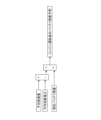
- FIG. 2 is a configuration explanatory diagram of an internal combustion engine;
- FIG. 4 is a characteristic diagram showing the relationship between a typical running pattern and target duration in the first embodiment;
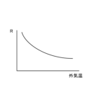
- FIG. 4 is a characteristic diagram showing the relationship between the outside air temperature and the temperature drop rate;
- Explanatory drawing which showed an example of the change of catalyst temperature and cooling water temperature.
- FIG. 11 is a characteristic diagram showing the relationship between the estimated running pattern, the catalyst temperature, and the cooling water temperature in the second embodiment;
- FIG. 11 is a characteristic diagram showing an example of temperature change in the third embodiment in which exhaust temperature rise control is performed;
- FIG. 11 is an explanatory diagram of prediction of battery SOC in the fourth embodiment; Explanatory drawing of the SOC change after an internal-combustion engine stop.
- FIG. 1 schematically shows the configuration of a series hybrid vehicle as an example of a hybrid vehicle to which the present invention is applied.
- the series hybrid vehicle includes a motor generator 1 for power generation that mainly operates as a power generator, an internal combustion engine 2 that is used as an internal combustion engine for power generation that drives the motor generator 1 for power generation according to electric power demand, and an internal combustion engine 2 that mainly operates as a motor.
- It is composed of a traveling motor generator 4 that drives the drive wheels 3 as a driving force, and a battery 5 that temporarily stores the generated electric power.
- Electric power obtained by the internal combustion engine 2 driving the motor generator 1 is stored in the battery 5 via an inverter device (not shown).
- the driving motor generator 4 is driven and controlled using the electric power of the battery 5 .
- Electric power generated during regeneration by the motor generator 4 for traveling is stored in the battery 5 via an inverter device (not shown).
- the controller 6 controls the operation of the motor generators 1 and 4, the charging and discharging of the battery 5, and the operation of the internal combustion engine 2.
- the controller 6 includes a plurality of controllers connected so as to communicate with each other, such as a motor controller 7 that controls the motor generators 1 and 4, an engine controller 8 that controls the internal combustion engine 2, and a battery controller 9 that manages the battery 5. It is Information such as the degree of opening of an accelerator pedal (not shown) and vehicle speed is input to the controller 6 .
- the battery controller 9 also obtains the SOC of the battery 5 based on the voltage/current of the battery 5 . Basically, the engine controller 8 is requested to start the internal combustion engine 2 based on this decrease in SOC.
- the vehicle of the embodiment is equipped with a car navigation system 10 using GPS including high-precision map information in order to obtain the position of the vehicle, the road on which it will travel, and the surrounding environment.
- a car navigation system 10 using GPS including high-precision map information in order to obtain the position of the vehicle, the road on which it will travel, and the surrounding environment.
- one or a plurality of information acquisition devices 11 such as cameras are similarly provided to acquire information on the front or surrounding environment.
- a so-called connected car may have a connected system that constantly exchanges various information with the outside using an information communication function.
- FIG. 2 shows the system configuration of the internal combustion engine 2.
- the internal combustion engine 2 is, for example, a four-stroke cycle spark ignition internal combustion engine equipped with a turbocharger 12.
- a pair of intake valves 14 and a pair of exhaust valves 15 are arranged on the ceiling wall surface of each cylinder 13.
- an ignition plug 16 is arranged in a central portion surrounded by these intake valves 14 and exhaust valves 15 .
- a fuel injection valve 17 that supplies fuel into the cylinder 13 is provided below the intake valve 14 .
- the engine controller 8 controls the ignition timing of the ignition plug 16 and the injection timing and injection amount of fuel by the fuel injection valve 17 .
- the intake passage 21 has an intake collector 21a, and an electronically controlled throttle valve 22 whose opening is controlled by a control signal from the engine controller 8 is provided upstream of the intake collector 21a.
- a compressor 12a of the turbocharger 12 is positioned upstream of the throttle valve 22, and an air flow meter 24 and an air cleaner 25 for detecting the amount of intake air are disposed upstream of the compressor 12a.
- a water-cooled intercooler 26, for example, is provided between the compressor 12a and the throttle valve 22 to cool the high temperature and high pressure intake air.
- a recirculation valve 27 is provided to communicate the discharge side and the suction side of the compressor 12a.
- a turbine 12b of the turbocharger 12 is located in the exhaust passage 30, and a pre-catalyst device 31 and a main catalyst device 32 each comprising a three-way catalyst are disposed downstream thereof.
- the pre-catalyst device 31 is arranged at the outlet of the turbine 12b, and the main catalytic device 32 is arranged under the floor of the vehicle.
- An air-fuel ratio sensor 33 that detects the air-fuel ratio is arranged upstream of the turbine 12b in the exhaust passage 30 .
- Turbine 12b includes a wastegate valve 34 that bypasses a portion of the exhaust in response to boost pressure to control boost pressure.
- the wastegate valve 34 is, for example, of an electric type whose opening is controlled by the engine controller 8 .
- an exhaust gas recirculation passage 35 for recirculating part of the exhaust gas from the exhaust passage 30 to the intake passage 21 is provided. It is
- the engine controller 8 includes a crank angle sensor 41 for detecting the engine speed, a water temperature sensor 42 for detecting the cooling water temperature, a pre-catalyst device 31 and a main catalyst device. Sensors such as catalyst temperature sensors 43 and 44 for detecting catalyst temperatures of 32, atmospheric pressure sensor 45 for detecting atmospheric pressure, outside temperature sensor 46 for detecting outside temperature, and supercharging pressure sensor 47 for detecting supercharging pressure. A type of detection signal is input. Based on these detection signals and requests from other controllers 7 and 9, the engine controller 8 optimally controls the fuel injection amount, injection timing, ignition timing, opening of the throttle valve 22, supercharging pressure, etc. there is Instead of directly detecting the carrier temperature of the catalyst, the catalyst temperature sensors 43 and 44 may indirectly determine the catalyst temperature from the temperature of the gas before and after the catalyst.
- the internal combustion engine 2 is basically started when the SOC of the battery 5 drops to a predetermined starting SOC value, and the internal combustion engine 2 stops when the SOC reaches a sufficient level. In addition to the start/stop of the internal combustion engine 2 based on such a power generation request, the internal combustion engine 2 is started/stopped in order to appropriately maintain the warm-up state of the internal combustion engine 2 .
- catalyst temperature and cooling water temperature are monitored as temperature parameters indicating the warm-up state of the internal combustion engine 2 .
- the catalyst temperature in one example, the temperature of the pre-catalyst device 31 detected by the catalyst temperature sensor 43 is used as a representative, but the temperature of the main catalyst device 32 may be used.
- FIG. 5 shows basic starting and stopping of the internal combustion engine 2 based on (a) catalyst temperature and (b) cooling water temperature while the vehicle is running.
- the catalyst temperature drops to a predetermined activation temperature TC1 corresponding to the first threshold value
- the internal combustion engine 2 is started.
- the internal combustion engine 2 is stopped when the catalyst temperature rises to the operation end temperature TC2 corresponding to the second threshold value.
- the temperature of the catalyst gradually decreases due to natural heat radiation, cooling effect due to running wind, and the like.
- the catalyst temperature drops to the activation temperature TC1
- the internal combustion engine 2 is started again. By such repetition, the catalyst temperature is maintained at the activation temperature TC1 or higher. While the internal combustion engine 2 is stopped, the vehicle travels in the EV mode described above.
- the internal combustion engine 2 is started when the cooling water temperature drops to a predetermined lower limit water temperature TW1 corresponding to the first threshold. After that, as the internal combustion engine 2 is operated, the internal combustion engine 2 is stopped when the cooling water temperature rises to the operation end temperature TW2 corresponding to the second threshold value. When the internal combustion engine 2 stops, the temperature of the cooling water gradually decreases due to the cooling effect of natural heat radiation and running wind. When the cooling water temperature drops to the lower limit water temperature TW1, the internal combustion engine 2 is started again. By such repetition, the cooling water temperature is maintained at or above the lower limit water temperature TW1.
- the lower limit water temperature TW1 is set, for example, to a temperature approximately equal to the warm-up completion temperature of a general internal combustion engine.
- the internal combustion engine 2 is started when the temperature drops to the activation temperature TC1 or the lower limit water temperature TW1.
- the internal combustion engine 2 may be started when both are lowered to the activation temperature TC1 and the lower limit water temperature TW1.
- the timing at which the catalyst temperature reaches the operation end temperature TC2 and the timing at which the cooling water temperature reaches the operation end temperature TW2 match as much as possible.
- the internal combustion engine 2 is stopped when both water temperatures reach the operation end temperatures TC2 and TW2.
- the internal combustion engine 2 may be stopped when either one reaches the operation end temperature TC2, TW2.
- the operation end temperatures TC2 and TW2 are set so that the duration of the EV mode operation after the internal combustion engine 2 is stopped (the time from the stop of the internal combustion engine 2 to the next start) is a desired target duration. It is set based on the respective temperature drop characteristics during EV mode operation of the catalyst temperature and the cooling water temperature.
- the target duration of EV mode driving is fixed in advance with reference to statistical processing of driving patterns (for example, WLTC, etc.) representative of the market as illustrated in FIG. given as a value.
- driving patterns for example, WLTC, etc.
- the target duration Tev of the EV mode driving is set corresponding to a period during which relatively gentle driving is performed.
- the target duration Tev can be on the order of minutes.
- a temperature drop rate R per unit time is given as the temperature drop characteristic during EV mode operation.
- Ra is the temperature decrease rate of the catalyst temperature
- Rb is the temperature decrease rate of the cooling water temperature.
- the temperature drop rate R may be an experimentally determined constant value, but in one embodiment is determined as a function of at least one of the outside air temperature and vehicle speed.
- FIG. 4 shows, for example, the characteristics of the temperature drop rate R with respect to the outside air temperature, and the lower the outside air temperature, the larger the temperature drop rate R becomes. The same applies to the vehicle speed, and the higher the vehicle speed, the larger the temperature drop rate R becomes.
- the temperature decrease rate Rb of the cooling water temperature may be set to different values according to the ON/OFF state of the heating switch in the passenger compartment air conditioner. That is, when the heating switch is on, heat is consumed for heating, so the temperature drop rate Rb is relatively large. Of course, when obtaining the temperature decrease rate R, conditions other than the outside air temperature, the vehicle speed, and the ON/OFF state of the heating switch may be taken into consideration.
- the target EV mode operation duration Tev is ensured by the time the catalyst temperature and cooling water temperature drop to the activation temperature TC1 and the lower limit water temperature TW1 next time. Then, the timing at which the catalyst temperature reaches the activation temperature TC1 coincides with the timing at which the cooling water temperature reaches the lower limit water temperature TW1.
- the vehicle of the embodiment is equipped with a car navigation system 10 including high-precision map information to obtain information on the position of the vehicle, the road on which it will travel, and the surrounding environment.
- Various information can be obtained by The controller 6 uses these road information, past travel data of the own vehicle, traffic statistics data, etc. to predict a travel pattern, for example, as illustrated in the upper part of FIG.
- the start/stop timing (in other words, the period during which the EV mode operation should be performed) that can optimize the fuel consumption of the own vehicle is determined.
- EV1", “EV2”, and “EV3" in FIG. 6 indicate periods during which the EV mode operation should be performed in the predicted driving pattern. That is, in the second embodiment, the target EV mode driving duration Tev is dynamically given based on the predicted driving pattern.
- the operation end temperatures TC2 and TW2 for the catalyst temperature and cooling water temperature are determined based on the target EV mode operation duration Tev and the temperature drop rates Ra and Rb, as in the first embodiment. As is clear from FIG. 6, since the length of each period (time) of "EV1”, “EV2”, and “EV3” is different, each of "EV1", “EV2”, and “EV3” , TW2 have different values. Conversely, by appropriately setting the operation end temperatures TC2 and TW2, the target durations of the EV mode operation can be appropriately obtained as indicated by “EV1", "EV2", and “EV3". It will happen. In FIG. 6, the operation end temperature for each of "EV1", “EV2”, and “EV3” is indicated as "TC2_EV1" and the like.
- both the catalyst temperature and the cooling water temperature reach the operation end temperatures TC2 and TW2 just at the timing when the internal combustion engine 2 is to be stopped.
- the responsiveness to changes in cooling water temperature is lower than the responsiveness to changes in catalyst temperature. If the catalyst temperature reaches the operation end temperature TW2 prior to , exhaust heat will be wasted.
- the increase in the cooling water temperature is monitored without increasing the catalyst temperature excessively higher than the activation temperature TC1, and the exhaust temperature increase control is started at the timing when the cooling water temperature approaches the operation end temperature TW2. do.
- This exhaust temperature increase control causes the catalyst temperature to rise sharply, so that it reaches the operation end temperature TC2 almost simultaneously with the cooling water temperature.
- Exhaust temperature increase control can be realized by, for example, ignition timing retarding or other known methods.
- FIG. 8 is a block diagram showing the logic for estimating the SOC of the battery 5 accompanying the combustion operation of the internal combustion engine 2.
- the average power consumption is subtracted from the average power generation amount, and the current remaining amount of the battery 5 (that is, By adding this to the current SOC), the remaining amount of the battery 5 after the combustion operation of the internal combustion engine 2 has been continued for a certain period of time (that is, the SOC when the operation is stopped) can be estimated.
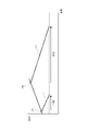
- FIG. 9 shows an example of changes in the SOC of the battery 5 due to combustion operation of the internal combustion engine 2 and EV mode operation.
- the target duration Tev of the EV mode operation is set relatively short (that is, the operation end temperatures TC2 and TW2 are relatively low) and when the target duration Tev is set relatively long (that is, the operation ends (temperatures TC2 and TW2 are relatively high).
- the line L1 is an example in which the target duration Tev is set short.
- the internal combustion engine 2 stops (that is, power generation ends) and the SOC decreases due to EV mode operation.
- the internal combustion engine 2 is started due to the power generation request relatively early (n1 seconds), and although there is a margin before the start request in terms of the catalyst temperature and the cooling water temperature, Starting of the internal combustion engine 2 may be started.
- the duration of the EV mode operation corresponding to the operation end temperatures TC2 and TW2 cannot be obtained.
- Line L2 is an example in which the target duration Tev is set long.
- the internal combustion engine 2 stops (that is, power generation ends), and the SOC decreases due to EV mode operation.
- the SOC at the time of shutdown is high, the time until a power generation request is generated becomes longer (n2 seconds), and the catalyst temperature and the cooling water temperature first decrease to the activation temperature TC1 or the lower limit water temperature TW1, and warm up occurs. can occur.
- the optimum stop timing of the internal combustion engine 2 exists between the line L1 and the line L2 (in other words, between the points P1 and P2).
- the timing of the start request based on the SOC decrease and the timing of the start request based on the temperature decrease of the internal combustion engine 2 (the activation temperature TC1 or the lower limit water temperature TW1 decrease) will coincide with each other.
- the condition in which the timings of the start requests based on these two conditions match is the condition that can maximize the duration of the EV mode operation.
- the controller 6 sequentially predicts the timings of the two start requests, and obtains the target duration Tev and the corresponding end temperatures TC2 and TW2 so that they match.
- the present invention is not limited to the above embodiment, and various modifications are possible.
- a series hybrid vehicle has been described as an example, but the present invention can be widely applied to any hybrid vehicle capable of EV mode operation.
- the catalyst temperature and the cooling water temperature are used as temperature parameters.
- the first threshold that defines the starting of the internal combustion engine 2 is not necessarily limited to a fixed value. If the first threshold changes under some conditions, the second threshold may be changed accordingly.
- the timing of engine start/stop does not necessarily have to be determined by the controller 6 in the vehicle, and in some cases, connected services, such as those provided from the cloud environment based on the driving plan and driving pattern analysis of the own vehicle. It doesn't matter if it is. That is, even if it is the in-vehicle controller 6 that gives the final start/stop command to the engine, the vehicle does not necessarily have the function of determining the start/stop timing.
Landscapes
- Engineering & Computer Science (AREA)
- Transportation (AREA)
- Mechanical Engineering (AREA)
- Automation & Control Theory (AREA)
- Chemical & Material Sciences (AREA)
- Combustion & Propulsion (AREA)
- Mathematical Physics (AREA)
- Physics & Mathematics (AREA)
- Human Computer Interaction (AREA)
- Hybrid Electric Vehicles (AREA)
- Output Control And Ontrol Of Special Type Engine (AREA)
- Control Of Vehicle Engines Or Engines For Specific Uses (AREA)
- Electric Propulsion And Braking For Vehicles (AREA)
Priority Applications (5)
| Application Number | Priority Date | Filing Date | Title |
|---|---|---|---|
| CN202180100636.1A CN117651665A (zh) | 2021-07-26 | 2021-07-26 | 混合动力车辆的内燃机的启动和停止控制方法以及装置 |
| JP2023537738A JP7460026B2 (ja) | 2021-07-26 | 2021-07-26 | ハイブリッド車両における内燃機関の始動・停止制御方法および装置 |
| PCT/JP2021/027467 WO2023007528A1 (ja) | 2021-07-26 | 2021-07-26 | ハイブリッド車両における内燃機関の始動・停止制御方法および装置 |
| US18/578,750 US12570269B2 (en) | 2021-07-26 | 2021-07-26 | Method and device for controlling starting and stopping of internal combustion engine in hybrid vehicle |
| EP21951132.6A EP4378776A4 (en) | 2021-07-26 | 2021-07-26 | METHOD AND DEVICE FOR CONTROLLING THE START AND STOP OF AN INTERNAL COMBUSTION ENGINE IN A HYBRID VEHICLE |
Applications Claiming Priority (1)
| Application Number | Priority Date | Filing Date | Title |
|---|---|---|---|
| PCT/JP2021/027467 WO2023007528A1 (ja) | 2021-07-26 | 2021-07-26 | ハイブリッド車両における内燃機関の始動・停止制御方法および装置 |
Publications (1)
| Publication Number | Publication Date |
|---|---|
| WO2023007528A1 true WO2023007528A1 (ja) | 2023-02-02 |
Family
ID=85086382
Family Applications (1)
| Application Number | Title | Priority Date | Filing Date |
|---|---|---|---|
| PCT/JP2021/027467 Ceased WO2023007528A1 (ja) | 2021-07-26 | 2021-07-26 | ハイブリッド車両における内燃機関の始動・停止制御方法および装置 |
Country Status (5)
| Country | Link |
|---|---|
| US (1) | US12570269B2 (https=) |
| EP (1) | EP4378776A4 (https=) |
| JP (1) | JP7460026B2 (https=) |
| CN (1) | CN117651665A (https=) |
| WO (1) | WO2023007528A1 (https=) |
Families Citing this family (1)
| Publication number | Priority date | Publication date | Assignee | Title |
|---|---|---|---|---|
| US20250033528A1 (en) * | 2022-03-09 | 2025-01-30 | Nissan Motor Co., Ltd. | Hybrid vehicle control method and hybrid vehicle control device |
Citations (3)
| Publication number | Priority date | Publication date | Assignee | Title |
|---|---|---|---|---|
| JP2005163545A (ja) | 2002-07-29 | 2005-06-23 | Mitsubishi Fuso Truck & Bus Corp | ハイブリッド電気自動車のエンジン制御装置 |
| JP2010221897A (ja) * | 2009-03-24 | 2010-10-07 | Toyota Motor Corp | ハイブリッド車および内燃機関の失火判定方法 |
| WO2012131941A1 (ja) * | 2011-03-30 | 2012-10-04 | トヨタ自動車株式会社 | 車両、エンジンの制御方法およびエンジンの制御装置 |
Family Cites Families (11)
| Publication number | Priority date | Publication date | Assignee | Title |
|---|---|---|---|---|
| JP3578044B2 (ja) * | 2000-04-21 | 2004-10-20 | トヨタ自動車株式会社 | ハイブリット車の内燃機関制御装置 |
| JP3576969B2 (ja) * | 2000-12-19 | 2004-10-13 | 株式会社日立製作所 | 車両の制御装置 |
| JP3809824B2 (ja) * | 2002-09-10 | 2006-08-16 | トヨタ自動車株式会社 | ハイブリッド車 |
| JP5104708B2 (ja) * | 2008-10-10 | 2012-12-19 | トヨタ自動車株式会社 | ハイブリッド車両の制御装置および制御方法 |
| JP5217991B2 (ja) * | 2008-12-09 | 2013-06-19 | トヨタ自動車株式会社 | ハイブリッド車およびその制御方法 |
| JP4911206B2 (ja) * | 2009-08-31 | 2012-04-04 | トヨタ自動車株式会社 | 車両の制御装置および制御方法 |
| JP5817741B2 (ja) * | 2011-02-16 | 2015-11-18 | トヨタ自動車株式会社 | 車両および車両の制御方法 |
| US8989935B2 (en) * | 2013-03-22 | 2015-03-24 | Ford Global Technologies, Llc | Method and system for engine control |
| JP6424566B2 (ja) * | 2014-10-30 | 2018-11-21 | トヨタ自動車株式会社 | ハイブリッド車両の制御装置 |
| JP2016112910A (ja) * | 2014-12-11 | 2016-06-23 | 本田技研工業株式会社 | ハイブリッド車両の制御装置 |
| US11199118B2 (en) * | 2018-08-27 | 2021-12-14 | Ford Global Technologies, Llc | Systems and methods for reducing cold start emissions for autonomous vehicles |
-
2021
- 2021-07-26 WO PCT/JP2021/027467 patent/WO2023007528A1/ja not_active Ceased
- 2021-07-26 JP JP2023537738A patent/JP7460026B2/ja active Active
- 2021-07-26 US US18/578,750 patent/US12570269B2/en active Active
- 2021-07-26 EP EP21951132.6A patent/EP4378776A4/en not_active Withdrawn
- 2021-07-26 CN CN202180100636.1A patent/CN117651665A/zh active Pending
Patent Citations (3)
| Publication number | Priority date | Publication date | Assignee | Title |
|---|---|---|---|---|
| JP2005163545A (ja) | 2002-07-29 | 2005-06-23 | Mitsubishi Fuso Truck & Bus Corp | ハイブリッド電気自動車のエンジン制御装置 |
| JP2010221897A (ja) * | 2009-03-24 | 2010-10-07 | Toyota Motor Corp | ハイブリッド車および内燃機関の失火判定方法 |
| WO2012131941A1 (ja) * | 2011-03-30 | 2012-10-04 | トヨタ自動車株式会社 | 車両、エンジンの制御方法およびエンジンの制御装置 |
Non-Patent Citations (1)
| Title |
|---|
| See also references of EP4378776A4 |
Also Published As
| Publication number | Publication date |
|---|---|
| JPWO2023007528A1 (https=) | 2023-02-02 |
| EP4378776A1 (en) | 2024-06-05 |
| US20240317211A1 (en) | 2024-09-26 |
| EP4378776A4 (en) | 2024-10-02 |
| CN117651665A (zh) | 2024-03-05 |
| JP7460026B2 (ja) | 2024-04-02 |
| US12570269B2 (en) | 2026-03-10 |
Similar Documents
| Publication | Publication Date | Title |
|---|---|---|
| US6520160B2 (en) | Internal combustion engine control unit for, and method of controlling a hybrid vehicle | |
| US10280823B2 (en) | Engine control device | |
| JP2005273530A (ja) | 内燃機関の制御装置およびこれを備える自動車 | |
| JPH1089053A (ja) | ハイブリッド型車両 | |
| JPH11210448A (ja) | ハイブリット車の内燃機関制御装置 | |
| JP6763488B2 (ja) | 車両用内燃機関の制御方法および制御装置 | |
| JP6844555B2 (ja) | センサシステム | |
| JP7460026B2 (ja) | ハイブリッド車両における内燃機関の始動・停止制御方法および装置 | |
| JP7676924B2 (ja) | ハイブリッド車両の暖機制御方法および暖機制御装置 | |
| JP6695626B2 (ja) | 制御装置 | |
| KR20230099750A (ko) | 마일드 하이브리드 시스템의 egr 응축수 유입 대응 장치 및 방법 | |
| JP2009174501A (ja) | 内燃機関装置およびその制御方法並びに動力出力装置 | |
| JP7694226B2 (ja) | 排気系温度推定装置 | |
| WO2021059794A1 (ja) | 車両制御システム及び内燃機関制御装置 | |
| JPH05328527A (ja) | ハイブリッド車の発電用内燃エンジンの運転方法 | |
| WO2025041345A1 (ja) | 内燃機関の再始動制御方法および装置 | |
| CN117377605B (en) | Control method for hybrid vehicle and control device for hybrid vehicle | |
| WO2026009339A1 (ja) | 内燃機関の加速時制御方法および装置 | |
| JP2021001580A (ja) | 内燃機関の制御方法および制御装置 | |
| JP7433713B2 (ja) | 内燃機関の制御装置 | |
| JP6065430B2 (ja) | 車両用エンジンの暖機促進装置 | |
| WO2024201092A1 (ja) | ハイブリッド車両の内燃機関の暖機制御方法および装置 | |
| WO2025262869A1 (ja) | 内燃機関の加速時制御方法および装置 | |
| JP2024069812A (ja) | 内燃機関の排気還流制御方法および装置 | |
| JP6763489B2 (ja) | 車両用内燃機関の制御方法および制御装置 |
Legal Events
| Date | Code | Title | Description |
|---|---|---|---|
| 121 | Ep: the epo has been informed by wipo that ep was designated in this application |
Ref document number: 21951132 Country of ref document: EP Kind code of ref document: A1 |
|
| WWE | Wipo information: entry into national phase |
Ref document number: 2023537738 Country of ref document: JP |
|
| WWE | Wipo information: entry into national phase |
Ref document number: 18578750 Country of ref document: US |
|
| WWE | Wipo information: entry into national phase |
Ref document number: 202180100636.1 Country of ref document: CN |
|
| WWE | Wipo information: entry into national phase |
Ref document number: 2021951132 Country of ref document: EP |
|
| NENP | Non-entry into the national phase |
Ref country code: DE |
|
| ENP | Entry into the national phase |
Ref document number: 2021951132 Country of ref document: EP Effective date: 20240226 |
|
| WWW | Wipo information: withdrawn in national office |
Ref document number: 2021951132 Country of ref document: EP |
|
| WWG | Wipo information: grant in national office |
Ref document number: 18578750 Country of ref document: US |