WO2023002564A1 - 車両のカウルルーバ - Google Patents
車両のカウルルーバ Download PDFInfo
- Publication number
- WO2023002564A1 WO2023002564A1 PCT/JP2021/027119 JP2021027119W WO2023002564A1 WO 2023002564 A1 WO2023002564 A1 WO 2023002564A1 JP 2021027119 W JP2021027119 W JP 2021027119W WO 2023002564 A1 WO2023002564 A1 WO 2023002564A1
- Authority
- WO
- WIPO (PCT)
- Prior art keywords
- vehicle
- cowl louver
- groove
- extension
- windshield
- Prior art date
- Legal status (The legal status is an assumption and is not a legal conclusion. Google has not performed a legal analysis and makes no representation as to the accuracy of the status listed.)
- Ceased
Links
Images





Classifications
-
- B—PERFORMING OPERATIONS; TRANSPORTING
- B62—LAND VEHICLES FOR TRAVELLING OTHERWISE THAN ON RAILS
- B62D—MOTOR VEHICLES; TRAILERS
- B62D25/00—Superstructure or monocoque structure sub-units; Parts or details thereof not otherwise provided for
- B62D25/08—Front or rear portions
Definitions
- the present invention relates to a vehicle cowl louver that is arranged between a vehicle windshield and an engine hood.
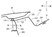
- the cowl top cover 10X described in Japanese Patent Laying-Open No. 2012-101697 includes, as shown in FIG. and
- the connection portion 20X extends from the lower end portion of the windshield 7X toward the front side of the vehicle on the side of the bonnet hood 8X.
- the hood contact portion 30X is formed with an upright wall portion 31X that rises from the front end of the connection portion 20X in the height direction of the vehicle.
- a seal member 37X that is pressed against the bonnet hood 8X and an air intake 12X are provided on the upper surface of the hood contact portion 30X.
- This air intake port 12X is a through hole for taking in outside air, and is also used for drainage of rainwater and the like.
- the hood contact portion 30X is supported by the vehicle body panel 90X via the vertical wall 35X extending downward in the height direction of the vehicle.
- the vertical wall 35X is formed in a horizontal U shape with the vehicle front side open, and the vehicle front side of the vertical wall 35X is reinforced by a plate-shaped reinforcing rib 36X extending in the height direction of the vehicle. .
- the vertical wall 35X and the reinforcing rib 36X are each formed with a groove-shaped bending line XL at the center in the height direction of the vehicle.
- the air intake 12X is used for water drainage, and the air intake 12X is formed at a position higher than the connecting portion 20X. Therefore, when rainwater or the like flowing down from the windshield 7X accumulates at the intersection 25X between the connecting portion 20X and the standing wall portion 31X, it is difficult to drain the collected rainwater or the like. Further, in the cowl top cover 10X, the bending line XL is formed between the vertical wall 35X and the reinforcing rib 36X in order to ensure shock absorption. There is The present invention has been made in view of the above points, and an object of the present invention is to more reliably secure drainage and impact absorption of the cowl louver.
- a vehicle cowl louver of a first invention is arranged between a windshield and an engine hood of a vehicle, and includes an extension portion connected to the windshield and a support portion for supporting the engine hood. are formed to extend in the vehicle width direction.
- the extension part of the present invention extends from the lower end of the windshield toward the engine hood, and the support part is formed with a standing wall part that rises upward in the height direction of the vehicle from the engine hood side end of the extension part. It is A groove portion is formed at the intersection of the extension portion and the vertical wall portion on the design surface side.
- the groove formed at the intersection on the design surface side can be used as a drainage channel for water flowing down from the windshield to the extension.
- the impact load applied to the engine hood is absorbed by the support portion of the cowl louver deforming downward in the height direction of the vehicle.
- the support portion can be smoothly deformed downward in the height direction of the vehicle, triggered by the groove portion provided at the intersection with the extension portion.
- the vehicle cowl louver of the second invention is the vehicle cowl louver of the first invention, wherein the groove extends in the vehicle width direction.
- the groove portion of the present invention extends in the vehicle width direction along the extension portion and the support portion. Therefore, the water flowing down to the extension can be guided in the vehicle width direction through the groove, and the groove can be used as a trigger to smoothly deform the support section to which the impact load is applied.
- the vehicle cowl louver of the third invention is the vehicle cowl louver of the first invention or the second invention, wherein the groove communicates with a drain hole penetrating the cowl louver from the design side to the opposite back side.
- the water that has flowed down from the windshield to the extension can be guided to the drain hole provided in the cowl louver through the groove formed at the intersection.
- a vehicle cowl louver is the vehicle cowl louver according to any one of the first to third aspects of the invention, in which an extension portion and a standing wall portion are formed in a region in which a plurality of protrusions projecting upward in the height direction of the vehicle are formed. At least part of the intersection is located, and the groove is formed so as to divide a plurality of or a single projection extending from the windshield side to the engine hood side.
- the strength of the crossing point in normal times is ensured in the region where the convex portion is provided. Then, the support portion to which the impact load is applied can be deformed downward in the height direction of the vehicle, triggered by the groove portion that divides the convex portion in the area.
- the first aspect of the present invention it is possible to more reliably ensure the drainage and impact absorption of the cowl louver.
- the second invention it is possible to more reliably ensure the drainage and impact absorption of the cowl louver.
- the third invention it is possible to more reliably ensure the drainage performance of the cowl louver.
- the fourth aspect of the invention it is possible to more reliably ensure shock absorption while ensuring the normal strength of the cowl louver.
- FIG. 1 is a schematic perspective view of a front portion of a vehicle
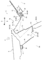
- FIG. FIG. 2 is a cross-sectional view taken along the line II-II of FIG. 1
- It is a perspective view of the left side of a cowl louver.
- FIG. 4 is a schematic perspective view of the portion indicated by symbol IV in FIG. 3;
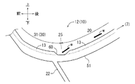
- FIG. 4 is an enlarged perspective view of the cowl louver showing grooves;
- FIG. 6 is a sectional view taken along the line VI-VI of FIG. 5;
- FIG. 6 is a cross-sectional view taken along line VII-VII of FIG. 5; 6 is a cross-sectional view taken along line VIII-VIII of FIG. 5;
- FIG. and FIG. 11 is a schematic cross-sectional view of a vehicle front structure showing a conventional cowl top cover.
- FIG. 1 A mode for carrying out the present invention will be described below with reference to FIGS. 1 to 8.
- FIG. 1 arrows indicating the front-rear direction, the left-right direction (vehicle width direction), and the up-down direction (vehicle height direction) are shown as appropriate.
- FIG. 1 for convenience, only the members on the right side of the vehicle are denoted by corresponding reference numerals.
- FIG. 4 for the sake of convenience, the projections of the outside air introduction portion are shown with dashed lines, and the respective lid portions are shown with solid lines.
- FIG. 1 Left and right door openings 4 that are opened and closed by front doors 3 are provided on the left and right sides of the front body of the vehicle 2, as shown in FIG.
- a front pillar 5 is erected at the front edge of each door opening 4, and the left and right front pillars 5 support a front portion of a roof panel (not shown).
- the left and right front pillars 5 are covered with a fender panel 6 at the pillar strut portions 5a below the beltline BR of the front door 3.
- the design portion 5b of the front pillar 5 located above the fender panel 6 is continuous with the design surface of the fender panel 6.
- a windshield 7 is provided at a position surrounded by the design portions 5b of the left and right front pillars 5 and the roof panel.
- An engine hood 8 is provided between the left and right fender panels 6 so as to open and close the engine room ER of the vehicle.
- a cowl louver 10 extending in the vehicle width direction (horizontal direction) is provided on the rear side of the engine room ER.
- a dash panel (not shown) partitioning the engine room ER and the vehicle compartment R is provided in the form of a vertical wall extending in the vehicle width direction.
- the cowl louver 10 is arranged between the windshield 7 and the engine hood 8, as shown in FIG. That is, the rear end side of the cowl louver 10 is connected to the lower end portion 70 of the windshield 7 and the rear end portion of the engine hood 8 is supported on the front side of the cowl louver 10 .
- the front side of the cowl louver 10 is supported by a cowl panel 9 provided above a dash panel (not shown). That is, a flange-shaped louver support portion 91 for supporting the cowl louver 10 is provided at the front end portion (cowl front panel 90) of the cowl panel 9 so as to extend in the vehicle width direction. It is
- the cowl louver 10 described above is a vehicle body exterior part that guides water flowing down from the windshield 7 to both ends in the vehicle width direction of the vehicle 2 and has a function of introducing outside air.
- the cowl louver 10 has an outside air introduction portion 12 (details will be described later) formed on the left side, and a hole H through which the rotation shaft of the wiper (not shown) passes is formed on the right side.
- a rain gutter 40 (details will be described later) is fixed to the rear end of the cowl louver 10 .
- the design surface (upper surface in each figure) of the cowl louver 10 is gently slanted downward to the right from the left portion toward the center in the vehicle width direction.
- the outside air introduction part 12 formed on the left side of the cowl louver 10 is also inclined downward to the right, and is gradually inclined downward in the height direction of the vehicle from the left side to the right side.
- the cowl louver 10 is formed with an extension portion 20 connected to the lower end portion 70 of the windshield 7 and a support portion 30 for supporting the engine hood 8 so as to extend in the vehicle width direction. (Details of the extension portion 20 and the support portion 30 will be described later). It is desirable that the cowl louver 10 have excellent drainage properties, and it is particularly desirable to ensure the drainage properties of rainwater or the like that has flowed down from the windshield 7 to the extended portion 20 .
- the impact load F applied from the height direction of the vehicle is absorbed by the support portion 30 supporting the engine hood 8 being deformed downward in the vehicle height direction.
- the arrow indicating the direction in which the load is applied is attached with a symbol F indicating the load).
- cowl louver 10 In this type of cowl louver 10, it is desirable to ensure shock absorption regardless of restrictions such as the shape of the support portion 30 thereof. Therefore, in the present embodiment, the drainage performance and shock absorption performance of the cowl louver 10 are ensured more reliably by the structure described later. Each configuration of the cowl louver 10 will be described in detail below.
- the cowl louver 10 shown in FIG. 2 is formed with an extension portion 20 forming the rear side of the vehicle.
- the extended portion 20 has its rear end fixed and connected to the lower end portion 70 of the windshield 7 by a fixing member 21, and extends from the lower end portion 70 of the windshield 7 toward the engine hood 8 (FIG. 2). in front of).
- the extension part 20 is gently inclined along the windshield 7 in the longitudinal direction of the vehicle, and is gradually inclined downward in the height direction of the vehicle as it approaches the engine hood 8 .
- a support portion 30 which will be described later, is integrally formed at the front end of the extension portion 20 on the side of the engine hood 8 .
- the cowl louver 10 shown in FIG. 2 is formed with a support portion 30 forming the front side of the vehicle.
- a mountain-shaped portion 300 formed at the rear end portion and a groove-shaped portion 310 formed on the vehicle front side of the mountain-shaped portion 300 are formed so as to extend in the vehicle width direction.
- the mountain-like portion 300 projects upward in the height direction of the vehicle while being slightly forwardly inclined, and is formed of a rear wall portion 31 , a top portion 32 and a front wall portion 33 .
- the rear standing wall portion 31 of the mountain-like portion 300 corresponds to the standing wall portion of the present invention, and rises upward in the height direction of the vehicle from the front end of the extension portion 20 on the side of the engine hood.
- inclined to The top portion 32 extends toward the front side of the vehicle from the upper end of the rear standing wall portion 31 and gradually slopes downward in the height direction of the vehicle toward the front side of the vehicle.
- the front wall portion 33 extends downward in the height direction of the vehicle from the front end of the top portion 32, and the lower end of the front wall portion 33 is connected to the bottom wall portion 34 of the groove-shaped portion 310 described later.
- a groove-shaped portion 310 shown in FIG. 2 is a portion that is relatively recessed with respect to the mountain-shaped portion 300, and is a bottom wall portion 34 that extends from the front wall portion 33 toward the front of the vehicle and rises from the front end of the bottom wall portion 34. and an inclined wall portion 35 .
- the bottom wall portion 34 is supported while being placed on the louver support portion 91 of the cowl panel 9 . Furthermore, the space between the bottom wall portion 34 and the louver support portion 91 is sealed over the entire vehicle width direction with a sponge-like sealing material 92 .
- the inclined wall portion 35 rises from the bottom wall portion 34 while being inclined toward the front side of the vehicle, and a flange portion 36 constituting the front end portion of the cowl louver 10 is formed at the upper end position of the inclined wall portion 35 so as to extend in the vehicle width direction. ing.
- a rear end portion of the engine hood 8 is supported by the flange portion 36 , and a weather strip 37 is provided between the engine hood 8 and the flange portion 36 .
- This rain gutter 40 is formed to extend in the vehicle width direction as shown in FIG. As shown in FIG. 2, the rain gutter 40 is fixed to the rear side of the extension 20 of the cowl louver 10 (the side opposite to the design surface).
- the main body of the rain gutter 40 is formed to have a substantially L-shaped vertical cross-section. and a vertical plate portion 42 that is bent inward.
- the vertical plate portion 42 is integrally formed with a connecting plate portion 43 extending substantially perpendicularly toward the front of the vehicle.
- a fixture 44 passed through the connecting plate portion 43 is fixed to a tower-shaped fixed portion 22 projecting from the rear surface side of the extension portion 20 .
- a plurality of fixing points 45 to which the rain gutter 40 is fixed to the extension 20 are formed in the vehicle width direction in the outside air introduction section 12, which will be described later (see FIG. 4). 4, only some fixing points are shown for convenience).
- a plurality of lid portions 50 to 52 are formed in the outside air introduction portion 12 to cover the design surface side of the fixed portion 45 .
- the outside air introduction portion 12 shown in FIG. 3 is formed in a rectangular shape that is long in the vehicle width direction, and is formed so as to straddle the extension portion 20 and the rear wall portion 31 of the support portion 30 in the vehicle front-rear direction. As shown in FIGS. 4 and 5, the outside air introduction part 12 has a plurality of projections (13, 14) that protrude upward in the height direction of the vehicle. Strength is ensured over time.
- the outside air introduction part 12 corresponds to a region in which a plurality of protrusions are formed according to the present invention, and has a plurality of front and rear protrusions 13 and a plurality of left and right protrusions 14 (in each figure, for convenience, Reference numerals 13 and 14 corresponding to only some convex portions are attached).
- the plurality of front-rear protrusions 13 are protrusions extending in the vehicle front-rear direction (from the windshield side to the engine hood side), and are formed at approximately equal intervals in the vehicle width direction.
- the plurality of left and right protrusions 14 are protrusions extending in the vehicle width direction, and are formed at approximately equal intervals in the vehicle front-rear direction.
- the outside air introduction portion 12 has a lid portion 50 at the right side, a lid portion 51 at the center, and a lid portion 52 at the left side. is formed.
- Each of these lid portions 50 to 52 is formed in a rectangular shape elongated in the left and right direction in a plan view, and has a plurality of front and rear projections 13 formed on the upper surface serving as a design surface.
- the lid portion 51 at the central position is formed to be elongated in the vehicle front-rear direction, and is arranged so as to straddle the extension portion 20 and the rear wall portion 31 of the support portion 30 .
- the portions where the respective lid portions 50 to 52 exist are closed so as not to introduce the outside air.
- the portion (15) surrounded by the front and rear convex portions 13 and the left and right convex portions 14 penetrates the cowl louver 10 from the design surface side to the opposite back side. It is connected to the cowl panel side so that outside air can be introduced.
- a portion (15) surrounded by the front and rear protrusions 13 and the left and right protrusions 14 is used as a drain hole 16 for draining water from the cowl louver 10 (in each figure, for convenience, only a portion of the drain hole is shown). with reference numeral 16 corresponding only to ).
- the cowl louver 10 is formed with an intersection 25 between the rear wall portion 31 of the support portion 30 and the extension portion 20 so as to extend in the vehicle width direction.
- This intersection point 25 is a boundary between the base end of the rear wall portion 31 and the front end of the extension portion 20, and is formed at the lowest front end position of the extension portion 20 as shown in FIG.
- the portion (part) on the left side of the intersection 25 overlaps with the outside air introduction portion 12 described above, and crosses the lid portion 51 at the center position of the outside air introduction portion 12. is formed in A groove portion 60, which will be described later, is formed in the cover portion 51 at the central position at a position overlapping the intersection portion 25. As shown in FIG.
- the groove portion 60 shown in FIG. 5 is formed on the upper surface of the lid portion 51 at the central position, that is, on the design surface side of the intersection 25 (in FIG. 5, the lid portion 51 at the central position is hatched for convenience. do).
- the groove portion 60 extends in the vehicle width direction along the extension portion 20 and the rear wall portion 31 of the support portion 30 while traversing the central lid portion 51 . 5 and 6, the groove portion 60 is formed at the boundary between the front end (lowest portion) of the extension portion 20 and the base end of the rear wall portion 31. are divided in the vehicle front-rear direction. As shown in FIG.
- the groove 60 formed in the outside air introduction portion 12 is inclined downward to the right in the same manner as the outside air introduction portion 12, and gradually lowers in the height direction of the vehicle as it goes from the left side to the right side. inclined to 5 and 8, the lowest right end of the groove portion 60 communicates with the drain hole 16 located on the right side of the lid portion 51 at the central position.
- the formation positions of the grooves 60 in the vehicle front-rear direction are aligned with the positions of the left and right protrusions 14 on both sides in the vehicle width direction. Therefore, on the design surface side of the cowl louver 10, the groove 60 and the right and left projections 14 appear to be continuous, and the groove 60 is not excessively conspicuous. 7 and 8 , left and right projections 140 adjacent to the right side of groove 60 are notched at the upper side in the height direction of the vehicle so as to be substantially flush with the bottom surface of groove 60 . It has a semicircular shape. That is, the adjacent left and right convex portions 140 constitute a part of the groove portion 60 . Therefore, as will be described later, the water flowing through the groove 60 flows down into the drain hole 16 without being obstructed by the adjacent left and right protrusions 140 as much as possible.
- the cowl louver 10 [Performance of the cowl louver (function of the groove)] It is desirable for the cowl louver 10 shown in FIG. Further, it is desirable that the cowl louver 10 ensure shock absorption regardless of restrictions such as the shape of the support portion 30 . Therefore, in the cowl louver 10 , the extension 20 extends from the lower end of the windshield 7 toward the engine hood 8 . A rear wall portion 31 is formed that rises upward in the direction. A groove portion 60 is formed at the intersection 25 of the extension portion 20 and the rear standing wall portion 31 on the design surface side.
- the arrow indicating the direction of water flow is denoted by W). That is, rainwater or the like that has flowed down from the windshield 7 flows along the extension 20 toward the front of the vehicle, and then flows down into the groove 60 provided at the front end of the extension 20 .
- the groove portion 60 is inclined downward to the right as described above, and the right end of the groove portion 60 communicates with the drain hole 16 located on the right side of the lid portion 51 at the central position. Therefore, referring to FIGS.
- the water flowing down into the groove 60 flows from the left side to the right side in the vehicle width direction, and is guided to the drain hole 16 arranged on the right side of the groove section 60. become.
- rainwater or the like that has flowed down from the windshield 7 to the extended portion 20 can be guided to the drain hole 16 through the groove portion 60. It becomes difficult for water to accumulate at 25.
- the water on the extension 20 may be wiped off while being washed away in the vehicle width direction with a car washing tool. Even in such a case, water left unwiped can be drained from the groove portion 60 to the drain hole 16, which contributes to ensuring excellent car washability.
- the impact load F applied to the engine hood 8 shown in FIG. 2 is absorbed by the support portion 30 of the cowl louver 10 deforming downward in the height direction of the vehicle (indicated by a two-dot dashed line in FIG. 2). support).
- the mountain-like portion 300 of the support portion 30 rises in the height direction of the vehicle so that the impact load F applied from the engine hood 8 can be received.
- the mountain-like portion 300 bends and deforms downward in the height direction of the vehicle with the base end (intersection point 25) of the rear wall portion 31 as the base point of bending.
- a groove portion 60 provided at the base end (intersection point 25 ) of the rear wall portion 31 extends in the vehicle width direction along the rear wall portion 31 of the mountain-like portion 300 . Therefore, the mountain-shaped portion 300 of the support portion 30 to which the impact load F is applied is smoothly deformed downward in the height direction of the vehicle, triggered by the groove portion 60 formed along the rear wall portion 31. Become. In this way, in the cowl louver 10, the support part 30 can be smoothly deformed by using the groove part 60 formed at the intersection 25, so that impact absorption can be ensured regardless of the restriction on the shape of the support part 30. - ⁇ Further, by intentionally using the groove portion 60 as a base point for deformation of the support portion 30, damage (breakage) of unintended portions of the cowl louver 10 can be avoided as much as possible when the support portion 30 is deformed.
- the groove 60 formed at the intersection 25 on the design surface side can be used as a drainage channel for water flowing down from the windshield 7 to the extension 20 .
- the impact load F applied to the engine hood 8 is absorbed by the support portion 30 of the cowl louver 10 deforming downward in the height direction of the vehicle.
- the support portion 30 can smoothly deform downward in the height direction of the vehicle, triggered by the groove portion 60 provided at the intersection 25 with the extension portion 20 . Therefore, according to this embodiment, it is possible to more reliably ensure the drainage and impact absorption of the cowl louver 10 .
- the groove portion 60 of this embodiment extends in the vehicle width direction along the extension portion 20 and the support portion 30 . Therefore, the water flowing down to the extension portion 20 can be guided in the vehicle width direction through the groove portion 60, and the groove portion 60 serves as a trigger for smoother deformation of the support portion 30 to which the impact load F is applied. . Further, in this embodiment, water flowing down from the windshield 7 to the extended portion 20 can be guided to the drain hole 16 provided in the cowl louver 10 through the groove portion 60 formed at the intersection 25 . In this embodiment, the strength of the crossing point 25 in a normal state is ensured by the region (outside air introducing portion 12) provided with the projections 13 and 14. FIG. Then, the support portion 30 to which the impact load F is applied becomes deformable downward in the height direction of the vehicle, triggered by the groove portion 60 that divides the convex portion (13) in the area.
- the vehicle cowl louver of the present embodiment is not limited to the embodiment described above, and can take various other embodiments.
- the basic configuration of the cowl louver can be appropriately changed according to the vehicle type.
- the grooves ensure drainage and shock absorption
- the shape and dimensions of the extension and the support can be appropriately changed according to the vehicle type.
- the extension may be sloped more gently or steeply than the windshield.
- the configuration of the mountain-like portion and the groove-like portion of the support portion can be changed as appropriate.
- the region in which a plurality of protrusions are formed can be formed in the cowl louver independently of the external air introduction portion.
- the crossing point (groove) of the extension part and the support part can be formed at an appropriate position on the design surface of the cowl louver. you don't have to be
- the groove can be formed in part or all of the cowl louver in the vehicle width direction, and in addition to the case where it extends linearly in the left and right direction which is the vehicle width direction, it can be inclined in the vehicle front-rear direction, bent, or in the middle. It may be branched by . It is desirable that at least a part of the groove is formed along the extension or the standing wall.
- a drain hole can be provided at the end in the vehicle width direction according to the direction of inclination of the groove. For example, when the groove is inclined downward to the left, a drainage hole can be provided on the left end side. Also, a plurality of or a single drain hole can be provided at an appropriate position in the groove.
- a drain hole may be provided at the lowest position in the vehicle width direction, and grooves may be formed across the drain hole, or grooves may be formed on the left and right sides of the groove.
- the drain hole can be provided in the cowl louver independently of the outside air introduction portion.
- the groove can be formed so as to divide at least one (single) protrusion in the region.
- the slope of the groove portion may be the slope of the cowl louver (external air introduction portion) itself, or may be the slope provided by changing the depth of the groove portion.
Landscapes
- Engineering & Computer Science (AREA)
- Chemical & Material Sciences (AREA)
- Combustion & Propulsion (AREA)
- Transportation (AREA)
- Mechanical Engineering (AREA)
- Body Structure For Vehicles (AREA)
Priority Applications (2)
| Application Number | Priority Date | Filing Date | Title |
|---|---|---|---|
| JP2023536259A JP7491474B2 (ja) | 2021-07-20 | 2021-07-20 | 車両のカウルルーバ |
| PCT/JP2021/027119 WO2023002564A1 (ja) | 2021-07-20 | 2021-07-20 | 車両のカウルルーバ |
Applications Claiming Priority (1)
| Application Number | Priority Date | Filing Date | Title |
|---|---|---|---|
| PCT/JP2021/027119 WO2023002564A1 (ja) | 2021-07-20 | 2021-07-20 | 車両のカウルルーバ |
Publications (1)
| Publication Number | Publication Date |
|---|---|
| WO2023002564A1 true WO2023002564A1 (ja) | 2023-01-26 |
Family
ID=84979187
Family Applications (1)
| Application Number | Title | Priority Date | Filing Date |
|---|---|---|---|
| PCT/JP2021/027119 Ceased WO2023002564A1 (ja) | 2021-07-20 | 2021-07-20 | 車両のカウルルーバ |
Country Status (2)
| Country | Link |
|---|---|
| JP (1) | JP7491474B2 (https=) |
| WO (1) | WO2023002564A1 (https=) |
Citations (5)
| Publication number | Priority date | Publication date | Assignee | Title |
|---|---|---|---|---|
| JPH01161989U (https=) * | 1988-04-28 | 1989-11-10 | ||
| JP2009126188A (ja) * | 2007-11-19 | 2009-06-11 | Mazda Motor Corp | 車両のカウル部構造 |
| JP2009154811A (ja) * | 2007-12-27 | 2009-07-16 | Toyoda Gosei Co Ltd | カウルルーバ |
| JP2014189034A (ja) * | 2013-03-26 | 2014-10-06 | Mitsubishi Automob Eng Co Ltd | 車両のフロントデッキ構造 |
| JP2018131090A (ja) * | 2017-02-16 | 2018-08-23 | トヨタ車体株式会社 | 車両のカウル構造 |
Family Cites Families (1)
| Publication number | Priority date | Publication date | Assignee | Title |
|---|---|---|---|---|
| JP5459440B2 (ja) | 2011-02-24 | 2014-04-02 | トヨタ自動車株式会社 | 自動車用カウル部構造 |
-
2021
- 2021-07-20 JP JP2023536259A patent/JP7491474B2/ja active Active
- 2021-07-20 WO PCT/JP2021/027119 patent/WO2023002564A1/ja not_active Ceased
Patent Citations (5)
| Publication number | Priority date | Publication date | Assignee | Title |
|---|---|---|---|---|
| JPH01161989U (https=) * | 1988-04-28 | 1989-11-10 | ||
| JP2009126188A (ja) * | 2007-11-19 | 2009-06-11 | Mazda Motor Corp | 車両のカウル部構造 |
| JP2009154811A (ja) * | 2007-12-27 | 2009-07-16 | Toyoda Gosei Co Ltd | カウルルーバ |
| JP2014189034A (ja) * | 2013-03-26 | 2014-10-06 | Mitsubishi Automob Eng Co Ltd | 車両のフロントデッキ構造 |
| JP2018131090A (ja) * | 2017-02-16 | 2018-08-23 | トヨタ車体株式会社 | 車両のカウル構造 |
Also Published As
| Publication number | Publication date |
|---|---|
| JPWO2023002564A1 (https=) | 2023-01-26 |
| JP7491474B2 (ja) | 2024-05-28 |
Similar Documents
| Publication | Publication Date | Title |
|---|---|---|
| US20150015030A1 (en) | Structure for front portion of vehicle | |
| CN119099309A (zh) | 玻璃滑槽的角部构造 | |
| US12214826B2 (en) | Front structure of vehicle | |
| WO2007018032A1 (ja) | 車体構造 | |
| EP1870272B1 (en) | Vehicle with a retractable roof and a draining structure for the retractable roof | |
| EP3868586B1 (en) | Open roof construction for a vehicle | |
| US11981371B2 (en) | Front structure of vehicle | |
| JP5493476B2 (ja) | 車両のドア構造 | |
| WO2023002564A1 (ja) | 車両のカウルルーバ | |
| EP1872994B1 (en) | Connecting structure of drain hose | |
| JP4460421B2 (ja) | サンルーフ装置におけるガイドフレームの構造 | |
| EP3050730B1 (en) | Weather strip | |
| CN108146511B (zh) | 一种空气室结构及汽车 | |
| JP6792787B2 (ja) | 車両のカウル構造 | |
| JP2001278117A (ja) | 自動車のカウル部の車体構造 | |
| JP3362654B2 (ja) | 自動車のカウル構造 | |
| JP2022131150A (ja) | 車両用カウル構造 | |
| JP7342601B2 (ja) | 車両のカウルグリル構造 | |
| JP5717417B2 (ja) | カウルトップカバー | |
| JPH0589052U (ja) | 車両のルーフ構造 | |
| JP3974097B2 (ja) | カウルトップガーニッシュ構造 | |
| JP7726842B2 (ja) | ドアウェザーストリップ | |
| JP5311177B2 (ja) | 車両用スライドドアにおける排水構造 | |
| WO2023007527A1 (ja) | 車両のカウル構造 | |
| JP5116634B2 (ja) | 開閉体の排水構造 |
Legal Events
| Date | Code | Title | Description |
|---|---|---|---|
| 121 | Ep: the epo has been informed by wipo that ep was designated in this application |
Ref document number: 21950370 Country of ref document: EP Kind code of ref document: A1 |
|
| WWE | Wipo information: entry into national phase |
Ref document number: 2023536259 Country of ref document: JP |
|
| WWE | Wipo information: entry into national phase |
Ref document number: 202417003643 Country of ref document: IN |
|
| NENP | Non-entry into the national phase |
Ref country code: DE |
|
| 122 | Ep: pct application non-entry in european phase |
Ref document number: 21950370 Country of ref document: EP Kind code of ref document: A1 |