WO2022270311A1 - ソケット - Google Patents
ソケット Download PDFInfo
- Publication number
- WO2022270311A1 WO2022270311A1 PCT/JP2022/023122 JP2022023122W WO2022270311A1 WO 2022270311 A1 WO2022270311 A1 WO 2022270311A1 JP 2022023122 W JP2022023122 W JP 2022023122W WO 2022270311 A1 WO2022270311 A1 WO 2022270311A1
- Authority
- WO
- WIPO (PCT)
- Prior art keywords
- hole
- plunger
- taper angle
- taper
- insulating support
- Prior art date
- Legal status (The legal status is an assumption and is not a legal conclusion. Google has not performed a legal analysis and makes no representation as to the accuracy of the status listed.)
- Ceased
Links
Images
Classifications
-
- G—PHYSICS
- G01—MEASURING; TESTING
- G01R—MEASURING ELECTRIC VARIABLES; MEASURING MAGNETIC VARIABLES
- G01R1/00—Details of instruments or arrangements of the types included in groups G01R5/00 - G01R13/00 and G01R31/00
- G01R1/02—General constructional details
- G01R1/04—Housings; Supporting members; Arrangements of terminals
- G01R1/0408—Test fixtures or contact fields; Connectors or connecting adaptors; Test clips; Test sockets
- G01R1/0433—Sockets for IC's or transistors
- G01R1/0441—Details
- G01R1/0466—Details concerning contact pieces or mechanical details, e.g. hinges or cams; Shielding
-
- G—PHYSICS
- G01—MEASURING; TESTING
- G01R—MEASURING ELECTRIC VARIABLES; MEASURING MAGNETIC VARIABLES
- G01R1/00—Details of instruments or arrangements of the types included in groups G01R5/00 - G01R13/00 and G01R31/00
- G01R1/02—General constructional details
- G01R1/06—Measuring leads; Measuring probes
- G01R1/067—Measuring probes
- G01R1/06711—Probe needles; Cantilever beams; "Bump" contacts; Replaceable probe pins
- G01R1/06716—Elastic
- G01R1/06722—Spring-loaded
-
- G—PHYSICS
- G01—MEASURING; TESTING
- G01R—MEASURING ELECTRIC VARIABLES; MEASURING MAGNETIC VARIABLES
- G01R1/00—Details of instruments or arrangements of the types included in groups G01R5/00 - G01R13/00 and G01R31/00
- G01R1/02—General constructional details
- G01R1/06—Measuring leads; Measuring probes
- G01R1/067—Measuring probes
- G01R1/06711—Probe needles; Cantilever beams; "Bump" contacts; Replaceable probe pins
- G01R1/06733—Geometry aspects
-
- H—ELECTRICITY
- H01—ELECTRIC ELEMENTS
- H01R—ELECTRICALLY-CONDUCTIVE CONNECTIONS; STRUCTURAL ASSOCIATIONS OF A PLURALITY OF MUTUALLY-INSULATED ELECTRICAL CONNECTING ELEMENTS; COUPLING DEVICES; CURRENT COLLECTORS
- H01R13/00—Details of coupling devices of the kinds covered by groups H01R12/70 or H01R24/00 - H01R33/00
- H01R13/02—Contact members
- H01R13/22—Contacts for co-operating by abutting
- H01R13/24—Contacts for co-operating by abutting resilient; resiliently-mounted
- H01R13/2407—Contacts for co-operating by abutting resilient; resiliently-mounted characterized by the resilient means
- H01R13/2421—Contacts for co-operating by abutting resilient; resiliently-mounted characterized by the resilient means using coil springs
-
- H—ELECTRICITY
- H01—ELECTRIC ELEMENTS
- H01R—ELECTRICALLY-CONDUCTIVE CONNECTIONS; STRUCTURAL ASSOCIATIONS OF A PLURALITY OF MUTUALLY-INSULATED ELECTRICAL CONNECTING ELEMENTS; COUPLING DEVICES; CURRENT COLLECTORS
- H01R33/00—Coupling devices specially adapted for supporting apparatus and having one part acting as a holder providing support and electrical connection via a counterpart which is structurally associated with the apparatus, e.g. lamp holders; Separate parts thereof
- H01R33/74—Devices having four or more poles, e.g. holders for compact fluorescent lamps
- H01R33/76—Holders with sockets, clips, or analogous contacts adapted for axially-sliding engagement with parallely-arranged pins, blades, or analogous contacts on counterpart, e.g. electronic tube socket
-
- H—ELECTRICITY
- H01—ELECTRIC ELEMENTS
- H01R—ELECTRICALLY-CONDUCTIVE CONNECTIONS; STRUCTURAL ASSOCIATIONS OF A PLURALITY OF MUTUALLY-INSULATED ELECTRICAL CONNECTING ELEMENTS; COUPLING DEVICES; CURRENT COLLECTORS
- H01R2201/00—Connectors or connections adapted for particular applications
- H01R2201/20—Connectors or connections adapted for particular applications for testing or measuring purposes
Definitions
- the present invention relates to sockets.
- a socket includes a probe and an insulating support provided with a through hole through which the probe is arranged.
- the probe has a first plunger that contacts the first electrode of the test object, a second plunger that contacts the second electrode of the test substrate, and a spring.
- the second plunger is brought into contact with the second electrode of the inspection substrate, the first plunger is urged upward by the spring, and then the first plunger is brought into contact with the first electrode of the inspection object. are in contact.
- a gap is provided between the outer surface of the probe and the inner surface of the through hole in order to allow the probe to slide within the through hole of the insulating support.
- the tip of the first plunger is released (that is, the tip of the first plunger is moved from the base end of the first plunger ( The first plunger may be urged upward when no external force directed toward the tip of the first plunger is applied to the tip of the first plunger.
- the gap between the outer surface of the probe and the inner surface of the through-hole may cause the first plunger to tilt, degrading the positional accuracy of the tip of the first plunger.
- One example of the object of the present invention is to improve the positional accuracy of the tip of the plunger. Other objects of the present invention will become clear from the description herein.
- One aspect of the present invention is a probe having a first tapered portion; an insulating support provided with a through hole having a second tapered portion for receiving the first tapered portion; with In the socket, the taper angle of the first taper portion is less than the taper angle of the second taper portion.
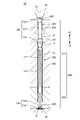
- FIG. 1 is a cross-sectional view of the socket 10 according to the embodiment.
- the socket 10 is positioned between the inspection object 20 and the inspection board 30 in the vertical direction.
- the inspection object 20 is positioned above the socket 10 .
- the test board 30 is positioned below the socket 10 .
- the inspection object 20 is, for example, an integrated circuit.
- the socket 10 includes a probe 100 and an insulating support 200.
- a first electrode 22 provided on the lower surface of the inspection object 20 and a second electrode 32 provided on the upper surface of the inspection substrate 30 are electrically connected to each other via the probes 100 .
- the first electrodes 22 are bumps and the second electrodes 32 are pads.
- the probe 100 has a tube 110 , a spring 112 , a first plunger 120 and a second plunger 130 .
- First plunger 120 includes a flange 122 , a first post 124 and a first contact portion 126 .
- the second plunger 130 includes a second post 134 and a second contact portion 136 .
- the insulating support 200 has a first insulating support 210 and a second insulating support 220 .
- the tube 110 extends parallel to the vertical direction.
- a first plunger 120 is provided at the upper end of the tube 110 .
- a second plunger 130 is provided at the lower end of the tube 110 .
- a spring 112 is provided inside the tube 110 . The spring 112 urges the first plunger 120 and the second plunger 130 vertically away from each other. In another example different from this embodiment, the tube 110 may not be provided and the spring 112 may be provided between the first plunger 120 and the second plunger 130 in the vertical direction.
- the flange 122 is positioned above the upper end of the tube 110 .
- the horizontal diameter of the flange 122 is substantially equal to the horizontal outer diameter of the tube 110 .
- the first column portion 124 extends vertically upward from the upper end of the flange 122 .
- the horizontal diameter of the first column portion 124 is smaller than the horizontal diameter of the flange 122 .
- the first contact portion 126 is provided at the tip of the first columnar portion 124 , that is, at the upper end of the first columnar portion 124 . In the inspection of the inspection object 20 , the first contact portion 126 contacts the first electrode 22 while the tube 110 and the first plunger 120 are integrally urged toward the inspection object 20 by the spring 112 . doing.
- the second column portion 134 extends vertically.
- the value of the horizontal diameter of the second column portion 134 is smaller than the value of the horizontal inner diameter of the tube 110 .
- the second column 134 With at least part of the second column 134 inserted through a hole provided in the lower end of the tube 110 , the second column 134 is attached to the tube 110 so as to be vertically movable.
- the second contact portion 136 is provided at the tip of the second column portion 134 , that is, at the lower end of the second column portion 134 . In the inspection of the inspection object 20 , the second contact portion 136 is in contact with the second electrode 32 while the second plunger 130 is biased toward the inspection board 30 by the spring 112 .
- the first insulating support 210 and the second insulating support 220 overlap vertically.
- the first insulating support 210 is positioned above the second insulating support 220 .
- the second insulating support 220 is positioned below the first insulating support 210 .
- the first insulating support 210 is, for example, a pin block, and the second insulating support 220 is, for example, a pin plate.
- a through hole 230 is provided in the insulating support 200 .
- the through hole 230 penetrates the insulating support 200 in the vertical direction.
- Through hole 230 includes first hole 232 , second hole 234 and third hole 236 . At least a portion of the probe 100 is arranged to penetrate through the through hole 230 in the vertical direction.
- the first hole 232 is formed by a portion of the first insulating support 210 including the lower end and the vertical central portion of the first insulating support 210, and the upper end and the second insulating support 220 of the second insulating support 220. and a portion including the vertical central portion.
- a portion of the first hole 232 that penetrates the lower end of the first insulating support 210 and a portion of the first hole 232 that penetrates the upper end of the second insulating support 220 communicate with each other in the vertical direction.
- At least a portion of the tube 110 and at least a portion of the flange 122 vertically pass through the first hole 232 .
- the value of the horizontal diameter of the first hole 232 of the first insulating support 210 is the horizontal outer diameter of the portion of the tube 110 that passes through the first hole 232 of the first insulating support 210 . and the horizontal diameter of the flange 122 . Also, the value of the horizontal diameter of the first hole 232 of the second insulating support 220 is the horizontal diameter of the portion of the tube 110 that penetrates the first hole 232 of the second insulating support 220 . It is larger than the outer diameter value.
- a gap is provided between the outer surface of the flange 122 and the inner surface of the first hole 232 of the first insulating support 210 .
- the tube 110 and the flange 122 are vertically slidable within the first hole 232 .
- the second hole 234 vertically penetrates a portion of the first insulating support 210 including the upper end of the first insulating support 210 .
- the lower end of the second hole 234 communicates with the upper end of the first hole 232 in the vertical direction.
- At least a portion of the first column portion 124 is arranged to pass through the second hole 234 .
- the horizontal diameter of the second hole 234 is less than the horizontal diameter of the first hole 232 .
- the horizontal diameter of the second hole 234 is equal to or less than the horizontal outer diameter of the tube 110 and equal to or less than the horizontal diameter of the flange 122 . greater than the value of the direction diameter. Therefore, the tube 110 and the flange 122 are prevented from coming out upward through the second hole 234 .
- a gap is provided between the outer surface of the first column portion 124 and the inner surface of the second hole 234 . Therefore, the first column portion 124 is slidable in the vertical direction within the second hole 234 .
- the third hole 236 vertically penetrates a portion of the second insulating support 220 including the lower end of the second insulating support 220 .
- the upper end of the third hole 236 communicates with the lower end of the first hole 232 in the vertical direction.
- At least a portion of the second column portion 134 is arranged to penetrate through the third hole 236 in the vertical direction.
- the horizontal diameter of the third hole 236 is less than the horizontal diameter of the first hole 232 .
- the horizontal diameter of the third hole 236 is less than or equal to the horizontal outer diameter of the tube 110 and is larger than the horizontal diameter of the second column portion 134 . Therefore, the tube 110 is prevented from coming out downward through the third hole 236 .
- a gap is provided between the outer surface of the second column portion 134 and the inner surface of the third hole 236 . Therefore, the second columnar portion 134 is slidable in the vertical direction within the third hole 236 .
- the first plunger 120 has a first tapered portion 102 .
- the first tapered portion 102 is positioned between the upper end of the flange 122 and the lower end of the first column portion 124 in the vertical direction.
- the horizontal diameter of the first plunger 120 at the first tapered portion 102 decreases from the upper end of the flange 122 toward the lower end of the first column portion 124 .
- the first taper angle ⁇ which is the taper angle of the first tapered portion 102, is set at the first taper portion 102 with respect to an imaginary line IL passing through the horizontal center of the through hole 230 in parallel with the extending direction of the through hole 230. It is the sum of the angles formed by the outer surfaces on both sides of the first plunger 120 in the horizontal direction.
- the first taper angle ⁇ is also the angle formed by the tangent lines of the outer side surfaces of the first plunger 120 on both sides in the horizontal direction of the first taper portion 102 .
- the through hole 230 has a second taper portion 202 .
- the second tapered portion 202 is positioned vertically between the upper end of the first hole 232 and the lower end of the second hole 234 .
- the horizontal diameter of the through hole 230 in the second tapered portion 202 decreases from the upper end of the first hole 232 toward the lower end of the second hole 234 .
- the second taper angle ⁇ which is the taper angle of the second tapered portion 202, is set at It is the sum of the angles formed by the inner surfaces on both sides of the through-hole 230 in the horizontal direction.
- the second taper angle ⁇ is also the angle formed by the tangent lines of the inner side surfaces on both sides of the through hole 230 in the second taper portion 202 in the horizontal direction.
- the first taper angle ⁇ of the first taper portion 102 is less than the second taper angle ⁇ of the second taper portion 202 .
- the ratio of the first taper angle ⁇ to the second taper angle ⁇ is not limited to, for example, 3/5 or more (i.e., 90% of 2/3 or more) and 33/40 or less (i.e., 3/4 of 110 % or less).
- the first taper angle ⁇ is not limited to the following, for example, even if it is 55.0° or more and 95.0° or less, good.
- the second taper angle ⁇ is not limited to the following, for example, even if it is 85.0° or more and 125.0° or less, good.
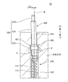
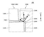
- FIG. 2 is a diagram for explaining a state in which the first plunger 120 is pushed upward through the through hole 230 with the first contact portion 126 opened in the socket 10 according to the embodiment.
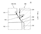
- FIG. 3 is an enlarged view of a portion of FIG. 2;
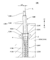
- FIG. 4 is a view for explaining a state in which the first plunger 120K is pushed upward through the through hole 230K with the first contact portion 126K opened in the socket 10K according to the comparative embodiment.
- 5 is an enlarged view of a portion of FIG. 4.
- FIGS. 2 and 3 The embodiment shown in FIGS. 2 and 3 will be described with reference to FIG.
- the downward external force is applied to the first contact portion.
- the second contact portion 136 is in contact with the second electrode 32 without joining the first contact portion 126 .
- the tube 110 and the first plunger 120 are integrally urged upward by the spring 112 , and the first plunger 120 is pushed upward through the through hole 230 .
- the gap between the outer surface of first post 124 and the inner surface of second hole 234 allows first plunger 120 to move perpendicular to the plane of the paper of FIGS. It is tilted to the left from the vertical direction when viewed from the normal direction.
- the first contact portion 126 is positioned leftward by a first distance ⁇ 1 from an imaginary line IL that passes through the horizontal center of the through hole 230 in parallel with the vertical direction when viewed from the direction perpendicular to the paper surface of FIG. 2 . out of alignment.
- the inclination of the first plunger 120 from the vertical direction is not limited to the embodiment shown in FIGS.
- the first plunger 120 may tilt to the right from the vertical direction when viewed from the direction perpendicular to the paper surface of FIGS. 2 and 3 .
- the corner between the upper end of the inner surface of the second taper portion 202 and the lower end of the inner surface of the second hole 234 in the through hole 230 receives the first taper portion 102 .
- the first plunger 120 is pushed upward through the through-hole 230 by the spring 112
- the first taper portion 102 is pushed toward the second taper portion 202, and the first taper portion 102 and the second taper portion 202 are separated.
- a preload load F is applied to the first tapered portion 102 at the contact portion with the .
- the preload load F in the embodiment is decomposed into a first force component F1 indicated by F sin ⁇ and a second force component F2 indicated by F cos ⁇ .
- the angle ? It is the angle formed by the direction toward the side to be done.
- the first force component F1 is a force that brings the first plunger 120 closer to the center of the through hole 230 in the horizontal direction.
- the second component force F2 is a force that contributes to the frictional force that prevents the first plunger 120 from moving in the tangential direction of the outer surface of the first tapered portion 102 toward the center of the through hole 230 in the horizontal direction.
- the first electrode 22 is brought into contact with the first contact portion 126 to compress the spring 112 in the vertical direction.
- the first contact portion 126 contacts the first electrode 22 while the tube 110 and the first plunger 120 are integrally urged upward.
- a socket 10K according to the comparative embodiment is the same as the socket 10 according to the embodiment except for the following points.
- the first plunger 120K is biased upward by a spring 112K provided inside the tube 110K.
- the first plunger 120K has a first tapered portion 102K.
- the first tapered portion 102K is positioned vertically between the upper end of the flange 122K and the lower end of the first column portion 124K.
- the horizontal diameter of the first plunger 120K at the first tapered portion 102K decreases from the upper end of the flange 122K toward the lower end of the first column portion 124K.
- the through hole 230K of the insulating support 200K (first insulating support 210K) has a second tapered portion 202K.
- the second tapered portion 202K is positioned vertically between the upper end of the first hole 232K and the lower end of the second hole 234K.
- the horizontal diameter of the through hole 230K in the second tapered portion 202K decreases from the upper end of the first hole 232K toward the lower end of the second hole 234K.
- the first taper angle ⁇ of the first taper portion 102K is greater than or equal to the second taper angle ⁇ of the second taper portion 202K.
- the gap between the outer surface of the first post 124K and the inner surface of the second hole 234K allows the first plunger 120K to move perpendicular to the plane of the paper of FIGS. It is tilted to the left from the vertical direction when viewed from the normal direction.
- the first contact portion 126K is positioned leftward by a second distance ⁇ 2 from an imaginary line IL passing through the center of the through-hole 230K in parallel with the vertical direction when viewed from the direction perpendicular to the plane of FIG. out of alignment.
- the second tapered portion 202K receives the corner of the first plunger 120K between the lower end of the outer surface of the first tapered portion 102K and the upper end of the outer surface of the flange 122K.
- the first plunger 120K is pushed upward through the through hole 230K by the spring 112K, the first taper portion 102K is pushed toward the second taper portion 202K, and the first taper portion 102K and the second taper portion 202K are pushed.
- a preload load F is applied to the first plunger 120K at the contact portion.
- the preload load F in the comparative embodiment is decomposed into a first force component F1 indicated by F sin ⁇ and a second force component F2 indicated by F cos ⁇ .
- the angle ? It shows the direction toward the side to do and the angle formed.
- the first force component F1 is a force that brings the flange 122K closer to the center of the through hole 230K in the horizontal direction.
- the second component force F2 is a force that contributes to the frictional force that prevents the flange 122K from moving toward the center of the through hole 230K in the tangential direction of the inner surface of the second tapered portion 202K.
- the first distance ⁇ 1 of the horizontal deviation of the first contact portion 126 from the imaginary line IL in the embodiment is longer than the second distance ⁇ 2 of the horizontal deviation of the first contact portion 126K from the imaginary line IL in the comparative embodiment. can be made smaller.
- the reason is as follows. That is, in the embodiment, the preload load F can generate a torque that rotates the first plunger 120 counterclockwise when viewed from the direction perpendicular to the paper surface of FIG. 3 . Also in the comparative example, the preload load F can generate a torque that rotates the first plunger 120K counterclockwise when viewed from the direction perpendicular to the plane of FIG.
- the distance from the horizontal center of the first plunger 120 to the position where the preload load F is applied is shorter than the distance from the horizontal center of the first plunger 120K to the position where the preload load F is applied in the comparative embodiment. It's becoming Therefore, the torque generated by the preload load F in the embodiment can be made smaller than the torque generated by the preload load F in the comparative embodiment. Therefore, the first distance ⁇ 1 of the horizontal deviation of the first contact portion 126 from the imaginary line IL in the embodiment is the second distance of the horizontal deviation of the first contact portion 126K from the imaginary line IL in the comparative embodiment. It can be smaller than ⁇ 2.
- the positional accuracy of the tip of the first plunger 120 in the embodiment is the same as the positional accuracy of the tip of the first plunger 120K in the comparative embodiment. can do better. That is, the horizontal positional accuracy of the first contact portion 126 in the embodiment can be made better than the horizontal positional accuracy of the first contact portion 126K in the comparative embodiment.
- the first plunger 120 is directed above the through hole 230 as compared to the comparative embodiment.
- the first taper angle ⁇ may be an acute angle.
- the outer surface of the first taper portion 102 is more inclined than the inner surface of the second taper portion 202 in the through hole 230 . and the lower edge of the inner surface of the second hole 234 to facilitate the first plunger 120 to be horizontally centered in the through hole 230 .
- the coefficient of static friction and dynamic friction between the outer surface of the first tapered portion 102 and the corner between the upper end of the second tapered portion 202 and the lower end of the second hole 234 in the through hole 230 The coefficient may be less than or equal to a predetermined value.
- the static friction coefficient and the dynamic friction coefficient are equal to or less than a predetermined value, the outer surface of the first tapered portion 102 is formed through the through hole compared to the case where the static friction coefficient and the dynamic friction coefficient are greater than the predetermined value.
- the corner between the upper end of the second tapered portion 202 and the lower end of the second hole 234 can be easily slipped, and the first plunger 120 can be easily moved to the center of the through hole 230 in the horizontal direction. can be done.
- Table 1 shows the first taper angle ⁇ , the second taper angle ⁇ , the distance ⁇ , the angle ⁇ , and the ratio F1/ 2 is a table showing the relationship between F, ratio F2/F, and ratio F1/F2.
- the first taper angle ⁇ according to Examples 1 and 2 corresponds to the first taper angle ⁇ of the first tapered portion 102 described in the embodiment.
- the first taper angle ⁇ according to Comparative Examples 1 and 2 corresponds to the first taper angle ⁇ of the first tapered portion 102K described in the comparative example.
- Each numerical value in the row of " ⁇ (°)" in Table 1 indicates the second taper angle ⁇ (unit: °).
- the second taper angle ⁇ according to Examples 1 and 2 corresponds to the second taper angle ⁇ of the second taper portion 202 described in the embodiment.
- the second taper angle ⁇ according to Comparative Examples 1 and 2 corresponds to the second taper angle ⁇ of the second tapered portion 202K described in the comparative example.
- Each numerical value in the " ⁇ ( ⁇ m)" row in Table 1 indicates the distance ⁇ (unit: ⁇ m).
- the distance ⁇ in Examples 1 and 2 corresponds to the first distance ⁇ 1 of the horizontal deviation of the first contact portion 126 from the imaginary line IL described in the embodiment.
- the distance ⁇ in Comparative Examples 1 and 2 corresponds to the second distance ⁇ 2 of the horizontal deviation of the first contact portion 126K from the imaginary line IL described in the comparative example.
- Each numerical value in the "F1/F” row in Table 1 indicates the ratio of the first component force F1 to the preload load F.
- Each numerical value in the row of "F2/F” in Table 1 indicates the ratio of the second component force F2 to the preload load F.
- Each numerical value in the row of "F1/F2” in Table 1 indicates the ratio of the first force component F1 to the second force component F2.
- the preload load F, the first force component F1 and the second force component F2 in Examples 1 and 2 correspond to the preload load F, the first force component F1 and the second force component F2 described in the embodiment, respectively.
- the preload load F, the first force component F1, and the second force component F2 in Comparative Examples 1 and 2 correspond to the preload load F, the first force component F1, and the second force component F2 described in the comparative example, respectively.
- Example 1 In the simulations of Example 1, Example 2, Comparative Example 1 and Comparative Example 2, the first taper angle ⁇ and the second taper angle ⁇ were as shown in Table 1. In this simulation, the distance ⁇ , the angle ⁇ , the ratio F1/F, the ratio F2/F and the ratio F1/F2 are shown in Table 1.
- the distance ⁇ when the first taper angle ⁇ is less than the second taper angle ⁇ is It can be said that the distance ⁇ can be made smaller than the distance ⁇ in the case of ⁇ or more.
- Example 1 From the comparison between Example 1 and Example 2, when the first taper angle ⁇ is less than the second angle ⁇ , the larger the ratio F1/F2, the smaller the distance ⁇ . Further, from a comparison between Example 1 and Example 2, the distance ⁇ when the first taper angle ⁇ is an acute angle can be made smaller than the distance ⁇ when the first taper angle ⁇ is a right angle. It can be said.
- the ratio of the first taper angle ⁇ to the second taper angle ⁇ may be, for example, 3/5 or more and 33/40 or less.
- the lower limit of 3/5 of this numerical range indicates 90% of the ratio 2/3 of the first taper angle ⁇ to the second taper angle ⁇ in the first embodiment.
- the upper limit of 33/40 of this numerical range indicates 110% of the ratio 3/4 of the first taper angle ⁇ to the second taper angle ⁇ in the second embodiment.
- the first taper angle ⁇ is 58.0° or more and 62.0° or less, 58.5° or more and 61.5° or less, or 59.0° or more and 61.0° or less.
- the angle ⁇ may be 88.0° or more and 92.0° or less, 88.5° or more and 91.5° or less, or 89.0° or more and 91.0° or less.
- the above numerical range of the first taper angle ⁇ is estimated from 60° of the first taper angle ⁇ and its tolerance in the first embodiment.
- the above numerical range of the second taper angle ⁇ is estimated from the second taper angle ⁇ of 90° and its tolerance in the first embodiment.
- a third tapered portion in which the diameter of the probe 100 in the horizontal direction decreases from the top to the bottom is located in the portion of the outer surface of the probe 100 vertically between the tube 110 and the second plunger 130 .
- the horizontal diameter of the through-hole 230 decreases from the top to the bottom at the portion of the inner surface of the through-hole 230 that is positioned between the first hole 232 and the third hole 236 in the vertical direction.
- a fourth tapered portion may be provided. The fourth tapered portion receives the third tapered portion when the second plunger 130 is pushed downward.
- the third taper angle of the third taper portion is less than the fourth taper angle of the fourth taper portion.
- the positional accuracy of the tip of the second plunger 130 when the third taper angle is less than the fourth taper angle, that is, the positional accuracy of the second contact portion 136 in the horizontal direction is reduced when the third taper angle is equal to or greater than the fourth taper angle. This is better than the positional accuracy of the tip of the second plunger 130 in some cases, that is, the positional accuracy of the second contact portion 136 in the horizontal direction.
- Aspect 1 is a probe having a first tapered portion; an insulating support provided with a through hole having a second tapered portion for receiving the first tapered portion; with In the socket, the taper angle of the first taper portion is less than the taper angle of the second taper portion.
- the It is possible to reduce the inclination of the plunger provided with the 1-taper portion.
- the positional accuracy of the tip of the plunger in mode 1 can be better than the positional accuracy of the tip of the plunger when the taper angle of the first taper portion is equal to or greater than the taper angle of the second taper portion.
- the taper angle of the first tapered portion is the sum of the angles formed by the outer surfaces on both sides of the probe in the first tapered portion with respect to an imaginary line passing through the center of the through hole parallel to the extending direction of the through hole.
- the taper angle of the second tapered portion is the sum of the angles formed by the inner surfaces on both sides of the through hole in the second tapered portion with respect to an imaginary line passing through the center of the through hole parallel to the extending direction of the through hole. .
- Aspect 2 is The socket according to aspect 1, wherein the taper angle of the first taper portion is an acute angle. According to aspect 2, compared to the case where the taper angle of the first tapered portion is a right angle or an obtuse angle, the outer surface of the first tapered portion can be made easier to slide with respect to the through hole, and the first tapered portion can be The provided plunger can be easily moved to the center of the through hole.
Landscapes
- Physics & Mathematics (AREA)
- General Physics & Mathematics (AREA)
- Geometry (AREA)
- Engineering & Computer Science (AREA)
- Computer Hardware Design (AREA)
- Microelectronics & Electronic Packaging (AREA)
- Measuring Leads Or Probes (AREA)
- Testing Of Individual Semiconductor Devices (AREA)
- Connecting Device With Holders (AREA)
- Coupling Device And Connection With Printed Circuit (AREA)
Priority Applications (4)
| Application Number | Priority Date | Filing Date | Title |
|---|---|---|---|
| CN202280037582.3A CN117355754A (zh) | 2021-06-24 | 2022-06-08 | 插座 |
| US18/571,734 US20240295584A1 (en) | 2021-06-24 | 2022-06-08 | Socket |
| EP22828228.1A EP4361646A1 (en) | 2021-06-24 | 2022-06-08 | Socket |
| PH1/2023/553267A PH12023553267A1 (en) | 2021-06-24 | 2022-06-08 | Socket |
Applications Claiming Priority (2)
| Application Number | Priority Date | Filing Date | Title |
|---|---|---|---|
| JP2021-104560 | 2021-06-24 | ||
| JP2021104560A JP7734517B2 (ja) | 2021-06-24 | 2021-06-24 | ソケット |
Publications (1)
| Publication Number | Publication Date |
|---|---|
| WO2022270311A1 true WO2022270311A1 (ja) | 2022-12-29 |
Family
ID=84544282
Family Applications (1)
| Application Number | Title | Priority Date | Filing Date |
|---|---|---|---|
| PCT/JP2022/023122 Ceased WO2022270311A1 (ja) | 2021-06-24 | 2022-06-08 | ソケット |
Country Status (7)
| Country | Link |
|---|---|
| US (1) | US20240295584A1 (enExample) |
| EP (1) | EP4361646A1 (enExample) |
| JP (1) | JP7734517B2 (enExample) |
| CN (1) | CN117355754A (enExample) |
| PH (1) | PH12023553267A1 (enExample) |
| TW (1) | TW202305383A (enExample) |
| WO (1) | WO2022270311A1 (enExample) |
Citations (8)
| Publication number | Priority date | Publication date | Assignee | Title |
|---|---|---|---|---|
| JPH1019926A (ja) * | 1996-06-28 | 1998-01-23 | Nhk Spring Co Ltd | 導電性接触子 |
| JP2006308486A (ja) | 2005-04-28 | 2006-11-09 | Nhk Spring Co Ltd | 導電性接触子ホルダおよび導電性接触子ユニット |
| JP2013140058A (ja) * | 2011-12-29 | 2013-07-18 | Enplas Corp | プローブピン及び電気部品用ソケット |
| WO2019131438A1 (ja) * | 2017-12-26 | 2019-07-04 | 株式会社エンプラス | プローブピン及びソケット |
| WO2020202735A1 (ja) * | 2019-03-29 | 2020-10-08 | 山一電機株式会社 | コンタクトプローブ及びこれを備えた検査用ソケット |
| JP2021092435A (ja) * | 2019-12-10 | 2021-06-17 | 山一電機株式会社 | 検査用ソケット |
| JP2021104560A (ja) | 2019-12-26 | 2021-07-26 | 株式会社安永 | ワイヤ放電加工装置及びこのワイヤ放電加工装置に用いられるシート |
| JP2022079959A (ja) * | 2020-11-17 | 2022-05-27 | 山一電機株式会社 | 検査用ソケット |
Family Cites Families (9)
| Publication number | Priority date | Publication date | Assignee | Title |
|---|---|---|---|---|
| US5399982A (en) * | 1989-11-13 | 1995-03-21 | Mania Gmbh & Co. | Printed circuit board testing device with foil adapter |
| US5952843A (en) * | 1998-03-24 | 1999-09-14 | Vinh; Nguyen T. | Variable contact pressure probe |
| JP2006300581A (ja) * | 2005-04-18 | 2006-11-02 | Yokowo Co Ltd | プローブの組付け構造 |
| JP2010237133A (ja) * | 2009-03-31 | 2010-10-21 | Yokowo Co Ltd | 検査ソケットおよびその製法 |
| JP5361518B2 (ja) * | 2009-04-27 | 2013-12-04 | 株式会社ヨコオ | コンタクトプローブ及びソケット |
| JP6475479B2 (ja) * | 2014-11-27 | 2019-02-27 | 株式会社ヨコオ | 検査ユニット |
| JP2018194411A (ja) * | 2017-05-17 | 2018-12-06 | 株式会社ヨコオ | コンタクトプローブ及び検査用治具 |
| TWM588248U (zh) * | 2019-07-01 | 2019-12-21 | 技鼎股份有限公司 | 探針頭及其導電探針 |
| WO2023119897A1 (ja) * | 2021-12-21 | 2023-06-29 | 株式会社ヨコオ | プローブヘッド |
-
2021
- 2021-06-24 JP JP2021104560A patent/JP7734517B2/ja active Active
-
2022
- 2022-06-08 PH PH1/2023/553267A patent/PH12023553267A1/en unknown
- 2022-06-08 TW TW111121282A patent/TW202305383A/zh unknown
- 2022-06-08 CN CN202280037582.3A patent/CN117355754A/zh active Pending
- 2022-06-08 US US18/571,734 patent/US20240295584A1/en active Pending
- 2022-06-08 WO PCT/JP2022/023122 patent/WO2022270311A1/ja not_active Ceased
- 2022-06-08 EP EP22828228.1A patent/EP4361646A1/en not_active Withdrawn
Patent Citations (8)
| Publication number | Priority date | Publication date | Assignee | Title |
|---|---|---|---|---|
| JPH1019926A (ja) * | 1996-06-28 | 1998-01-23 | Nhk Spring Co Ltd | 導電性接触子 |
| JP2006308486A (ja) | 2005-04-28 | 2006-11-09 | Nhk Spring Co Ltd | 導電性接触子ホルダおよび導電性接触子ユニット |
| JP2013140058A (ja) * | 2011-12-29 | 2013-07-18 | Enplas Corp | プローブピン及び電気部品用ソケット |
| WO2019131438A1 (ja) * | 2017-12-26 | 2019-07-04 | 株式会社エンプラス | プローブピン及びソケット |
| WO2020202735A1 (ja) * | 2019-03-29 | 2020-10-08 | 山一電機株式会社 | コンタクトプローブ及びこれを備えた検査用ソケット |
| JP2021092435A (ja) * | 2019-12-10 | 2021-06-17 | 山一電機株式会社 | 検査用ソケット |
| JP2021104560A (ja) | 2019-12-26 | 2021-07-26 | 株式会社安永 | ワイヤ放電加工装置及びこのワイヤ放電加工装置に用いられるシート |
| JP2022079959A (ja) * | 2020-11-17 | 2022-05-27 | 山一電機株式会社 | 検査用ソケット |
Also Published As
| Publication number | Publication date |
|---|---|
| EP4361646A1 (en) | 2024-05-01 |
| US20240295584A1 (en) | 2024-09-05 |
| TW202305383A (zh) | 2023-02-01 |
| JP7734517B2 (ja) | 2025-09-05 |
| CN117355754A (zh) | 2024-01-05 |
| PH12023553267A1 (en) | 2024-04-22 |
| JP2023003466A (ja) | 2023-01-17 |
Similar Documents
| Publication | Publication Date | Title |
|---|---|---|
| TWI766154B (zh) | 探針頭及探針卡 | |
| JP6991782B2 (ja) | ソケット | |
| KR102566685B1 (ko) | 프로브 카드용 클램핑 장치 및 이를 포함하는 프로브 카드 | |
| WO2022270311A1 (ja) | ソケット | |
| TW201917389A (zh) | 檢查輔助具 | |
| CN109839522B (zh) | 探针卡装置及其信号转接模块 | |
| CN114336134B (zh) | Lga插座 | |
| US20250060393A1 (en) | Probe head | |
| JP7225052B2 (ja) | 電子部品モジュール | |
| JP2006222084A (ja) | ソケットコネクタ | |
| TWI747582B (zh) | 檢測裝置 | |
| KR102568131B1 (ko) | 소켓 | |
| JP2019174283A (ja) | 位置決め機構および検査装置 | |
| US20110053426A1 (en) | Lower profile electrical contact and electrical socket using the same | |
| KR20230143350A (ko) | 테스트 소켓용 콘택 핀 및 이를 포함하는 테스트 소켓 | |
| TW202443964A (zh) | 半導體插座 | |
| CN114429916B (zh) | 检测装置 | |
| TWI859603B (zh) | 片材以及檢查插座 | |
| JP2022182675A (ja) | 電気的接続装置 | |
| TWI642944B (zh) | 探針卡裝置及其信號轉接模組 | |
| TWI775509B (zh) | 探針頭及探針卡 | |
| TWI639009B (zh) | 探針卡裝置及其信號轉接模組 | |
| TWM621479U (zh) | 測試模組 | |
| JP2009162682A (ja) | プローブカード | |
| JP4420720B2 (ja) | 電気部品用ソケット |
Legal Events
| Date | Code | Title | Description |
|---|---|---|---|
| 121 | Ep: the epo has been informed by wipo that ep was designated in this application |
Ref document number: 22828228 Country of ref document: EP Kind code of ref document: A1 |
|
| WWE | Wipo information: entry into national phase |
Ref document number: 202280037582.3 Country of ref document: CN |
|
| WWE | Wipo information: entry into national phase |
Ref document number: 12023553267 Country of ref document: PH |
|
| WWE | Wipo information: entry into national phase |
Ref document number: 18571734 Country of ref document: US |
|
| WWE | Wipo information: entry into national phase |
Ref document number: 2022828228 Country of ref document: EP |
|
| NENP | Non-entry into the national phase |
Ref country code: DE |
|
| ENP | Entry into the national phase |
Ref document number: 2022828228 Country of ref document: EP Effective date: 20240124 |