WO2022264388A1 - 安全キャビネット - Google Patents
安全キャビネット Download PDFInfo
- Publication number
- WO2022264388A1 WO2022264388A1 PCT/JP2021/023124 JP2021023124W WO2022264388A1 WO 2022264388 A1 WO2022264388 A1 WO 2022264388A1 JP 2021023124 W JP2021023124 W JP 2021023124W WO 2022264388 A1 WO2022264388 A1 WO 2022264388A1
- Authority
- WO
- WIPO (PCT)
- Prior art keywords
- safety cabinet
- work chamber
- partition plate
- airflow
- work
- Prior art date
- Legal status (The legal status is an assumption and is not a legal conclusion. Google has not performed a legal analysis and makes no representation as to the accuracy of the status listed.)
- Ceased
Links
Images

Classifications
-
- F—MECHANICAL ENGINEERING; LIGHTING; HEATING; WEAPONS; BLASTING
- F24—HEATING; RANGES; VENTILATING
- F24F—AIR-CONDITIONING; AIR-HUMIDIFICATION; VENTILATION; USE OF AIR CURRENTS FOR SCREENING
- F24F3/00—Air-conditioning systems in which conditioned primary air is supplied from one or more central stations to distributing units in the rooms or spaces where it may receive secondary treatment; Apparatus specially designed for such systems
- F24F3/12—Air-conditioning systems in which conditioned primary air is supplied from one or more central stations to distributing units in the rooms or spaces where it may receive secondary treatment; Apparatus specially designed for such systems characterised by the treatment of the air otherwise than by heating and cooling
- F24F3/16—Air-conditioning systems in which conditioned primary air is supplied from one or more central stations to distributing units in the rooms or spaces where it may receive secondary treatment; Apparatus specially designed for such systems characterised by the treatment of the air otherwise than by heating and cooling by purification, e.g. by filtering; by sterilisation; by ozonisation
- F24F3/163—Clean air work stations, i.e. selected areas within a space which filtered air is passed
-
- B—PERFORMING OPERATIONS; TRANSPORTING
- B01—PHYSICAL OR CHEMICAL PROCESSES OR APPARATUS IN GENERAL
- B01L—CHEMICAL OR PHYSICAL LABORATORY APPARATUS FOR GENERAL USE
- B01L1/00—Enclosures; Chambers
- B01L1/04—Dust-free rooms or enclosures
-
- B—PERFORMING OPERATIONS; TRANSPORTING
- B01—PHYSICAL OR CHEMICAL PROCESSES OR APPARATUS IN GENERAL
- B01L—CHEMICAL OR PHYSICAL LABORATORY APPARATUS FOR GENERAL USE
- B01L1/00—Enclosures; Chambers
- B01L1/02—Air-pressure chambers; Air-locks therefor
-
- C—CHEMISTRY; METALLURGY
- C12—BIOCHEMISTRY; BEER; SPIRITS; WINE; VINEGAR; MICROBIOLOGY; ENZYMOLOGY; MUTATION OR GENETIC ENGINEERING
- C12M—APPARATUS FOR ENZYMOLOGY OR MICROBIOLOGY; APPARATUS FOR CULTURING MICROORGANISMS FOR PRODUCING BIOMASS, FOR GROWING CELLS OR FOR OBTAINING FERMENTATION OR METABOLIC PRODUCTS, i.e. BIOREACTORS OR FERMENTERS
- C12M1/00—Apparatus for enzymology or microbiology
-
- F—MECHANICAL ENGINEERING; LIGHTING; HEATING; WEAPONS; BLASTING
- F24—HEATING; RANGES; VENTILATING
- F24F—AIR-CONDITIONING; AIR-HUMIDIFICATION; VENTILATION; USE OF AIR CURRENTS FOR SCREENING
- F24F8/00—Treatment, e.g. purification, of air supplied to human living or working spaces otherwise than by heating, cooling, humidifying or drying
- F24F8/10—Treatment, e.g. purification, of air supplied to human living or working spaces otherwise than by heating, cooling, humidifying or drying by separation, e.g. by filtering
- F24F8/108—Treatment, e.g. purification, of air supplied to human living or working spaces otherwise than by heating, cooling, humidifying or drying by separation, e.g. by filtering using dry filter elements
-
- B—PERFORMING OPERATIONS; TRANSPORTING
- B01—PHYSICAL OR CHEMICAL PROCESSES OR APPARATUS IN GENERAL
- B01L—CHEMICAL OR PHYSICAL LABORATORY APPARATUS FOR GENERAL USE
- B01L2200/00—Solutions for specific problems relating to chemical or physical laboratory apparatus
- B01L2200/06—Fluid handling related problems
- B01L2200/0631—Purification arrangements, e.g. solid phase extraction [SPE]
-
- B—PERFORMING OPERATIONS; TRANSPORTING
- B01—PHYSICAL OR CHEMICAL PROCESSES OR APPARATUS IN GENERAL
- B01L—CHEMICAL OR PHYSICAL LABORATORY APPARATUS FOR GENERAL USE
- B01L2200/00—Solutions for specific problems relating to chemical or physical laboratory apparatus
- B01L2200/06—Fluid handling related problems
- B01L2200/0684—Venting, avoiding backpressure, avoid gas bubbles
-
- B—PERFORMING OPERATIONS; TRANSPORTING
- B01—PHYSICAL OR CHEMICAL PROCESSES OR APPARATUS IN GENERAL
- B01L—CHEMICAL OR PHYSICAL LABORATORY APPARATUS FOR GENERAL USE
- B01L2200/00—Solutions for specific problems relating to chemical or physical laboratory apparatus
- B01L2200/14—Process control and prevention of errors
- B01L2200/141—Preventing contamination, tampering
-
- B—PERFORMING OPERATIONS; TRANSPORTING
- B01—PHYSICAL OR CHEMICAL PROCESSES OR APPARATUS IN GENERAL
- B01L—CHEMICAL OR PHYSICAL LABORATORY APPARATUS FOR GENERAL USE
- B01L2300/00—Additional constructional details
- B01L2300/06—Auxiliary integrated devices, integrated components
- B01L2300/0681—Filter
-
- B—PERFORMING OPERATIONS; TRANSPORTING
- B01—PHYSICAL OR CHEMICAL PROCESSES OR APPARATUS IN GENERAL
- B01L—CHEMICAL OR PHYSICAL LABORATORY APPARATUS FOR GENERAL USE
- B01L2300/00—Additional constructional details
- B01L2300/08—Geometry, shape and general structure
- B01L2300/0848—Specific forms of parts of containers
- B01L2300/0858—Side walls
Definitions
- the present invention relates to a safety cabinet used for regenerative medicine, industrial use, development of pharmaceuticals, research on pathogens, etc.
- a safety cabinet is used when handling pathogens, etc. in the manipulation and observation of cells, research on pathogens such as viruses, and development of pharmaceuticals such as vaccine development.
- Patent Document 1 As an example of a safety cabinet, in Patent Document 1, a HEPA filter for blowing air is provided in the upper part of the work room, and a front shutter that can be opened and closed is provided in the front part of the work room. A grill is provided. Then, air is uniformly supplied into the work chamber from the HEPA filter for blowing, and air is drawn in from the front and rear grills of the work table that form the bottom of the work chamber, so that the air uniformly descends from top to bottom. and a safety cabinet for cleaning the workroom.
- Patent Document 1 In the safety cabinet disclosed in Patent Document 1, a worker sits in front of the safety cabinet and works by inserting his arm into the work room from the work opening below the front shutter. Installation and handling of devices such as cell manufacturing machines and transport machines in a safety cabinet is not considered. In other words, no consideration is given to the downflow wind velocity in the entire working room when the device is installed in the working room.
- An object of the present invention is to provide a safety cabinet that prevents contamination of cells, pathogens, etc. when a device such as a cell manufacturing machine such as a bio 3D printer or a transport machine is installed in the safety cabinet. and
- Another object is to provide a safety cabinet that can prevent cells, pathogens, etc. from leaking from inside the working room to the worker side.
- a work chamber that maintains a negative pressure state formed inside the front shutter, a lower surface side of the work chamber, and the work chamber. and a circulation channel formed from the side surface of the work chamber and the back side of the work chamber and the outer portion of the safety cabinet, wherein a device is mounted in the work chamber, wherein It has a partition plate so that the lower part of it has a wide horizontal cross-sectional area.
- safety cabinet Another example of the "safety cabinet” of the present invention is a safety cabinet having a front opening and a front shutter in the working room and supplying clean air from above into the working room.
- an exhaust slit is provided along the periphery of the device on the surface of the workbench on which the device connected to the exhaust circulation flow path under the workbench is installed.
- partition plates on the left and right sides and the rear surface of the upper side of the work chamber, it is possible to maintain a high wind speed that can guarantee a laminar flow in the work chamber, for example, a downflow air current equivalent to 0.45 m/s.
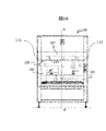
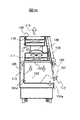
- FIG. 1 is a front view of the safety cabinet of Example 1.
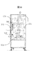
- FIG. 1 is a cross-sectional view of the safety cabinet of Example 1.
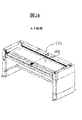
- FIG. 11 is a perspective view of the safety cabinet of Example 2;
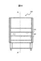
- 4 is a cross-sectional view of the safety cabinet of Example 2.
- FIG. It is a front view of a safety cabinet.
- Fig. 3 is a cross-sectional view of the safety cabinet;
- FIG. 3A shows a schematic front view of the safety cabinet
- FIG. 3B shows a schematic cross-sectional view of the safety cabinet as seen from the left side of the A-A' cross section in FIG. 3A.
- Safety cabinets include various cabinets for regenerative medicine and industrial use. In the following explanation, a specific explanation will be given as a safety cabinet used for drug development and pathogen research.
- a working room 102 whose front surface is composed of a front shutter 103 is arranged inside the safety cabinet 100.
- the work chamber 102 maintains a negative pressure state formed inside the front shutter.
- a work opening 104 is formed below the front shutter 103 , and an operator inserts his or her arm into the work chamber 102 through the work opening 104 and performs work while looking inside the work chamber 102 through the front shutter 103 .
- the lower surface of the work chamber 102 consists of the work table 101, and the front slit 104a is arranged on the front shutter 103 side of the work table 101.
- the safety cabinet fan 106 When the safety cabinet fan 106 operates, it pressurizes the pressure chamber 109 .
- a blowing HEPA filter 111 is connected to the pressure chamber 109. Dust in the pressure chamber 109 is filtered by the blowing HEPA filter 111, and the cleaned air is blown out. It is supplied as a blown airflow 113 into the room 102 .
- An exhaust HEPA filter 110 is also connected above the pressure chamber 109 . Air pressurized in pressure chamber 109 is filtered by exhaust HEPA filter 110 , passes through safety cabinet exhaust 108 , and exits safety cabinet 100 as exhaust air 114 .
- the incoming airflow 112 is sucked together with part of the blowing airflow 113 through a rear slit 105a formed on the opposite side of the front shutter 103 of the work chamber 102, passes through the circulation flow path 105, and is sucked into the safety cabinet fan 106.
- the circulation channel 105 is formed from the bottom side of the working chamber 102, the side side of the working chamber, the rear side of the working chamber and the outer part of the safety cabinet.
- the inflow airflow 112 sucked from the work opening 104 is channeled through the flow path composed of the lower part of the workbench 101 (the lower surface of the work chamber 102), the side and rear surfaces of the work chamber 102, and the main body of the safety cabinet 100. Circulate. Incoming airflow 112 through circulation channel 105 is drawn into safety cabinet fan 106 and exits safety cabinet 100 as exhaust air 114 .
- dust and aerosol containing pathogens and the like are handled in the working chamber 102, dust and aerosol containing pathogens and the like are also present in the circulation flow path 105 and the pressure chamber 109.
- the dust and aerosol are removed by a blow-out HEPA filter 111 when air is supplied to the work chamber 102 and by an exhaust HEPA filter 110 when air is exhausted from the safety cabinet 100 .
- the worker sits in front of the safety cabinet 100, inserts his arm into the work chamber 102 through the work opening 104, and works while looking inside the work chamber 102 through the front shutter 103.
- the down flow wind speed in the work room is set to a constant value, for example, 0.45 m. /s ⁇ 20% (0.36 to 0.54 m/s).
- the conventional safety cabinet fan 106 alone is insufficient in capacity to satisfy this demand. Therefore, an additional exhaust blower or a large-capacity circulation blower is required, which is a factor in increasing the size of the safety cabinet.
- a large-sized safety cabinet may not be able to be installed in an existing installation space or transported to the installation space.
- a high-velocity downflow airflow that can guarantee a laminar flow in the work room. can hold
- the safety cabinet of this embodiment it is possible to prevent leakage from the working room to the worker side.
- FIGS. 1A and 1B show a structural example of a safety cabinet 100 corresponding to the class II cabinet for biohazard countermeasures according to the first embodiment.
- FIG. 1A is a front view thereof.
- FIG. 1B is a cross-sectional view of the A-A' section of the safety cabinet 100 shown in FIG. 1A viewed from the left.
- the safety cabinet according to this embodiment has a front opening and a front shutter in the working room, supplies clean air to the working room from above, provides partition plates on the left and right sides and the back of the upper part of the working room, and further A partition is provided on the upper front side of the work chamber.
- FIG. 1A shows the safety cabinet 100 of Example 1 of the present invention.
- illumination suitable for work is maintained by illumination lamps.
- a germicidal lamp is installed on the upper back of the working room 102 . This germicidal lamp is used to supplement the sterilization of the work chamber 102 before and after work together with decontamination by wiping with 70% alcohol or the like.
- the safety cabinet 100 of Example 1 has side partitions 130 and rear partitions 131 on the left and right sides of the upper side of the work chamber.
- the side partition plate 130 and the rear partition plate 131 are attached in such a manner as to suppress the opening of the blow current plate 107 and restrict the blow portion of the blow air current 113 .
- the wind velocity of the blowing airflow 113 can be increased to 0.45 m/s ⁇ 20% (0.36 to 0.54 m/s).
- the side partition plate 130 and the rear partition plate 131 are inclined outward from about 150 mm below the blow current plate 107 . This inclination is such that the side surfaces of the safety cabinet 100 in the work chamber abut against the side partition plate 130 and the rear partition plate 131 at an angle 120, which is about 30 to 45 degrees.
- the inclination of the side partition plate 130 and the rear partition plate 131 minimizes the blowing-up of the blowing air current 113 and suppresses the stagnation of the blowing air current 113.
- the side partition plate 130 and the rear partition plate 131 are of a vertical sliding type so that the upper space of the work chamber 102 can be adjusted, and the shape is adapted to the device to be installed. may be made possible.
- the side partition plate 130 and the rear partition plate 131 are configured to slide up and down by about 100 mm to 200 mm. Although it depends on the machines installed in the work chamber 102, it is desirable to have a configuration that allows a vertical stroke of 50 mm to 300 mm in consideration of coping with more machines. By sliding the side partition plate 130 and the rear partition plate 131 up and down, it is possible to maintain the downflow wind speed while maintaining the laminar flow to the parts and work areas where cleanliness is required in the apparatus, thereby ensuring cleanliness. become able to.
- the side partition plate 130 and the rear partition plate 131 are inclined and slid up and down
- a mechanism for adjusting the inclination of the side partition plate 130 and the rear partition plate 131 may be provided.
- the side partition plate 130 and the rear partition plate 131 have been described as basically linear partition plates, they may be configured with curved lines convex to the working chamber 102 .
- the partition plates such as the side partition plate 130 and the rear partition plate 131 make the area near the upper portion of the work chamber 102 (air flow straightening plate 107) the smallest, and the side partition plate 130 and the rear partition plate 131 gradually widens to the point where it abuts on the side surface of the work chamber 102 .
- the airflow partition plate 132 on the upper front side of the work chamber, it is possible to secure clean air with a high wind speed in the device installation section where laminar flow and high cleanliness are required.
- the airflow partition plate 132 is installed at a predetermined distance from the front shutter 103 in the depth direction of the work chamber 102, for example, 30 mm to 100 mm.
- the airflow partition plate 132 is in contact with the blow current plate 107, faces downward in the work chamber 102, and has a length of 300 mm downward from the blow current plate 107, and controls the air flow from the blow current plate 107.
- a blowing air stream 113 and a front shutter back side air stream 133 - ⁇
- the front shutter 103 is attached so that the lower end of the front shutter 103 is positioned 200 mm above the workbench 101 .
- the lower end of the airflow partition plate 132 is positioned 250 mm above the lower end of the front shutter 103 .
- the vertical length of the airflow partition plate (Distance C) is 200 mm, 250 mm, and 300 mm, respectively.
- the airflow partition plate 132 prevents the rear surface of the front shutter 103 from increasing the airflow 133 on the side of the front shutter 103 facing the work chamber 102, and maintains the wind speed (0.30 to 0.40m/s) equivalent to that of the conventional safety cabinet. do.
- an air barrier can be maintained by the stable inflow airflow 112, and airflow balance performance, which is a stable airflow containment performance comparable to that of a safety cabinet, can be maintained.
- If the wind speed of the front shutter rear surface airflow 133 is too strong, the downflow airflow with a high wind speed directly hits the operator's arm, making it impossible to suppress contamination.
- the wind speed of the front shutter rear surface airflow 133 can be set to 0.30 to 0.40m/s, and contamination can be effectively suppressed.
- the inflow air current 112 having a high wind speed of about 0.60 m/s
- the downflow air current having a high wind speed of 0.45 m/s in the work chamber 102, which is partitioned by the side partition plate 130 and the rear partition plate 131
- the inflow airflow 112 and the blowing airflow 113 hit the work room 102 side of the airflow partition plate 132, resulting in the Coander effect.
- the air barrier effect of the air flow on the back side of the air flow partition plate 132 with increased air velocity can be promoted, and contamination due to the operation of the conveying section of the apparatus and manual work by a person can be suppressed.
- FIG. 2A is a perspective view of the safety cabinet of Example 2.
- FIG. 2B is a cross-sectional view of the A-A' section of the safety cabinet 100 shown in FIG. 2A viewed from above.
- the workbench 101 of the safety cabinet of the second embodiment is provided with a plurality of workbench exhaust slits 135 passing through the exhaust circulation flow path 134 (see FIG. 1B) according to the outer periphery of the device to be installed.
- a plurality of workbench exhaust slits 135 are provided on the left and right sides and the rear surface of the upper side of the work chamber of the safety cabinet 100, and near the work opening 104, that is, in the peripheral portion of the device installed on the workbench 101 (periphery of the workbench 101). be provided.
- Safety cabinet 101 Workbench 102 Work chamber 103 Front shutter 104 Work opening 105 Circulation channel 106 Safety cabinet fan 107 Blow rectifying plate 108 Air outlet 109 Pressure chamber 110 HEPA filter for exhaust 111 HEPA filter for blow 112 Inflow air flow 113 Blow Airflow 114 Exhaust air 130 Side partition plate 131 Rear partition plate 132 Airflow partition plate 133 Front shutter backside airflow 134 Exhaust circulation flow path 135 Workbench exhaust slit
Landscapes
- Chemical & Material Sciences (AREA)
- Engineering & Computer Science (AREA)
- Health & Medical Sciences (AREA)
- Clinical Laboratory Science (AREA)
- Chemical Kinetics & Catalysis (AREA)
- General Engineering & Computer Science (AREA)
- Mechanical Engineering (AREA)
- Combustion & Propulsion (AREA)
- Life Sciences & Earth Sciences (AREA)
- Bioinformatics & Cheminformatics (AREA)
- Wood Science & Technology (AREA)
- Biotechnology (AREA)
- Organic Chemistry (AREA)
- Zoology (AREA)
- Biomedical Technology (AREA)
- Sustainable Development (AREA)
- Microbiology (AREA)
- Biochemistry (AREA)
- General Health & Medical Sciences (AREA)
- Genetics & Genomics (AREA)
- Medicinal Chemistry (AREA)
- Devices For Use In Laboratory Experiments (AREA)
- Ventilation (AREA)
- Apparatus Associated With Microorganisms And Enzymes (AREA)
Abstract
Description
101 作業台
102 作業室内
103 前面シャッター
104 作業開口部
105 循環流路
106 安全キャビネットファン
107 吹き出し用整流板
108 排気口
109 圧力チャンバ
110 排気用HEPAフィルタ
111 吹き出し用HEPAフィルタ
112 流入気流
113 吹き出し気流
114 排気空気
130 側面仕切り板
131 背面仕切り板
132 気流仕切り板
133 前面シャッター裏面気流
134 排気循環流路
135 作業台排気スリット
Claims (8)
- 前面シャッターの内側に形成された作業室内と、
前記作業室内の下面側、前記作業室内の側面側および前記作業室内の背面側と安全キャビネットの外側部分とから形成される循環流路とを備え、前記作業室内に装置を搭載する安全キャビネットにおいて、
前記作業室内の上部よりも前記作業室内の下部が広い水平断面積となるように、仕切り板を有する
ことを特徴とする安全キャビネット。 - 請求項1に記載の安全キャビネットにおいて、
前記作業室に整流化した吹き出し気流を供給する吹き出し用整流板を有し、
前記仕切り板は、
前記吹き出し用整流板から下方へ所定距離から前記作業室内の側面へ傾斜する側面仕切り板と、
記吹き出し用整流板から下方へ所定距離から前記作業室内の背面へ傾斜する背面仕切り板と、を有する
ことを特徴とする安全キャビネット。 - 請求項2に記載の安全キャビネットにおいて、
前記前面シャッターから所定距離において、前記吹き出し用整流板から前記作業室内の下方に向かう気流仕切り板を有する
ことを特徴とする安全キャビネット。 - 請求項3に記載の安全キャビネットにおいて、
前記側面仕切り板及び前記背面仕切り板は、前記作業室内において上下にスライドするよう構成した
こと特徴とする安全キャビネット。 - 請求項3に記載の安全キャビネットにおいて、
前記側面仕切り板は、前記作業室内の側面と30度乃至45度の角度で当接するよう傾斜し、
前記背面仕切り板は、前記作業室内の側面と30度乃至45度の角度で当接するよう傾斜している
こと特徴とする安全キャビネット。 - 請求項3に記載の安全キャビネットにおいて、
前記気流仕切り板の下端は、前記前面シャッターの下端より上方である
ことを特徴とする安全キャビネット。 - 請求項6に記載の安全キャビネットにおいて、
前記気流仕切り板は、前記気流仕切り板と前記前面シャッターとの間の前面シャッター裏面気流を、前記作業室内の装置設置領域の気流より、風速をおさえるものである
ことを特徴とする安全キャビネット。 - 請求項2に記載の安全キャビネットにおいて、
前記作業室内の下面を構成し、前記装置を設置する作業台において、装置周囲に沿って排気用スリットを設けた
ことを特徴とする安全キャビネット。
Priority Applications (6)
| Application Number | Priority Date | Filing Date | Title |
|---|---|---|---|
| PCT/JP2021/023124 WO2022264388A1 (ja) | 2021-06-17 | 2021-06-17 | 安全キャビネット |
| JP2021567046A JP7196339B1 (ja) | 2021-06-17 | 2021-06-17 | 安全キャビネット |
| KR1020237017253A KR20230088829A (ko) | 2021-06-17 | 2021-06-17 | 안전 캐비닛 |
| CN202180003367.7A CN115884827A (zh) | 2021-06-17 | 2021-06-17 | 安全柜 |
| US17/620,785 US12130047B2 (en) | 2021-06-17 | 2021-06-17 | Safety cabinet |
| TW110141819A TWI800086B (zh) | 2021-06-17 | 2021-11-10 | 安全櫃 |
Applications Claiming Priority (1)
| Application Number | Priority Date | Filing Date | Title |
|---|---|---|---|
| PCT/JP2021/023124 WO2022264388A1 (ja) | 2021-06-17 | 2021-06-17 | 安全キャビネット |
Publications (1)
| Publication Number | Publication Date |
|---|---|
| WO2022264388A1 true WO2022264388A1 (ja) | 2022-12-22 |
Family
ID=84526969
Family Applications (1)
| Application Number | Title | Priority Date | Filing Date |
|---|---|---|---|
| PCT/JP2021/023124 Ceased WO2022264388A1 (ja) | 2021-06-17 | 2021-06-17 | 安全キャビネット |
Country Status (6)
| Country | Link |
|---|---|
| US (1) | US12130047B2 (ja) |
| JP (1) | JP7196339B1 (ja) |
| KR (1) | KR20230088829A (ja) |
| CN (1) | CN115884827A (ja) |
| TW (1) | TWI800086B (ja) |
| WO (1) | WO2022264388A1 (ja) |
Citations (4)
| Publication number | Priority date | Publication date | Assignee | Title |
|---|---|---|---|---|
| JPH04105884A (ja) * | 1990-08-23 | 1992-04-07 | Hitachi Ltd | 清浄作業台 |
| JP2004031928A (ja) * | 2002-05-07 | 2004-01-29 | Seiko Epson Corp | 清浄作業台 |
| JP2005156082A (ja) * | 2003-11-28 | 2005-06-16 | Hitachi Industrial Equipment Systems Co Ltd | 安全キャビネット |
| WO2015046413A1 (ja) * | 2013-09-30 | 2015-04-02 | パナソニックヘルスケアホールディングス株式会社 | 作業用チャンバー |
Family Cites Families (16)
| Publication number | Priority date | Publication date | Assignee | Title |
|---|---|---|---|---|
| US3000292A (en) * | 1958-01-23 | 1961-09-19 | Norbute Corp | Fume hood |
| US3811250A (en) * | 1971-12-15 | 1974-05-21 | Becton Dickinson Co | Contamination control apparatus |
| US3895570A (en) * | 1973-09-27 | 1975-07-22 | Baker Company Inc | Air-insulated work station |
| US4215627A (en) * | 1978-12-29 | 1980-08-05 | Garriss John E | Energy conserving laboratory hood system |
| US4637301A (en) * | 1984-02-06 | 1987-01-20 | Environmental Air Control, Inc. | Contamination control work station |
| JP3369661B2 (ja) * | 1993-09-09 | 2003-01-20 | 三洋電機株式会社 | 安全キャビネットの吸込装置 |
| KR20010113901A (ko) * | 1999-04-28 | 2001-12-28 | 스트라토테크 코포레이션 | 조정 가능한 청정 공기 유동 환경 |
| US8915984B2 (en) * | 2010-06-18 | 2014-12-23 | Airex Co., Ltd | Isolator device |
| JP5416666B2 (ja) * | 2010-07-20 | 2014-02-12 | 株式会社日立産機システム | 安全キャビネット |
| US9731335B2 (en) * | 2011-10-05 | 2017-08-15 | Lawrence Robert Meisenzahl | Vortex baffle for a ventilated enclosure |
| JP6486725B2 (ja) * | 2015-03-10 | 2019-03-20 | 株式会社日立産機システム | クリーンエア装置 |
| JP6771026B2 (ja) * | 2016-04-27 | 2020-10-21 | シャープ株式会社 | イオン発生装置、イオン発生装置を備えた空気調和機 |
| WO2018047409A1 (ja) * | 2016-09-09 | 2018-03-15 | 株式会社日立産機システム | 粒子計数器組み込み型隔離装置 |
| US10384243B2 (en) * | 2017-03-15 | 2019-08-20 | L.B.T. (Nantong) Laboratory Systems Engineering Co., Ltd. | Air replenishing fume hood |
| JP6711802B2 (ja) | 2017-10-13 | 2020-06-17 | 株式会社日立産機システム | 安全キャビネットおよびその排気ダクト接続の検査方法 |
| JP7182523B2 (ja) * | 2019-07-10 | 2022-12-02 | 株式会社日立産機システム | 安全キャビネット |
-
2021
- 2021-06-17 WO PCT/JP2021/023124 patent/WO2022264388A1/ja not_active Ceased
- 2021-06-17 CN CN202180003367.7A patent/CN115884827A/zh active Pending
- 2021-06-17 KR KR1020237017253A patent/KR20230088829A/ko active Pending
- 2021-06-17 JP JP2021567046A patent/JP7196339B1/ja active Active
- 2021-06-17 US US17/620,785 patent/US12130047B2/en active Active
- 2021-11-10 TW TW110141819A patent/TWI800086B/zh active
Patent Citations (4)
| Publication number | Priority date | Publication date | Assignee | Title |
|---|---|---|---|---|
| JPH04105884A (ja) * | 1990-08-23 | 1992-04-07 | Hitachi Ltd | 清浄作業台 |
| JP2004031928A (ja) * | 2002-05-07 | 2004-01-29 | Seiko Epson Corp | 清浄作業台 |
| JP2005156082A (ja) * | 2003-11-28 | 2005-06-16 | Hitachi Industrial Equipment Systems Co Ltd | 安全キャビネット |
| WO2015046413A1 (ja) * | 2013-09-30 | 2015-04-02 | パナソニックヘルスケアホールディングス株式会社 | 作業用チャンバー |
Also Published As
| Publication number | Publication date |
|---|---|
| JPWO2022264388A1 (ja) | 2022-12-22 |
| US20240027079A1 (en) | 2024-01-25 |
| US12130047B2 (en) | 2024-10-29 |
| JP7196339B1 (ja) | 2022-12-26 |
| TW202300222A (zh) | 2023-01-01 |
| KR20230088829A (ko) | 2023-06-20 |
| TWI800086B (zh) | 2023-04-21 |
| CN115884827A (zh) | 2023-03-31 |
Similar Documents
| Publication | Publication Date | Title |
|---|---|---|
| JP6228040B2 (ja) | 排気の循環利用型安全キャビネット及び排気の循環利用型安全キャビネットを備えるクリーンルームの空気循環システム | |
| WO2021005869A1 (ja) | 安全キャビネット | |
| JP6650048B2 (ja) | 安全キャビネット及びクリーンエア装置 | |
| WO2022003791A1 (ja) | 安全キャビネット | |
| JP7196339B1 (ja) | 安全キャビネット | |
| JP4255689B2 (ja) | 安全キャビネット | |
| WO2017203755A1 (ja) | 安全キャビネットおよびアイソレータ | |
| JPH01288342A (ja) | 清浄キャビネット | |
| JP4374294B2 (ja) | 安全キャビネット | |
| JP7249437B1 (ja) | 安全キャビネット | |
| KR20220043005A (ko) | 안전 캐비닛 | |
| JP4513275B2 (ja) | 清浄作業台 | |
| KR102834901B1 (ko) | 안전 작업 장치 | |
| JP3510617B2 (ja) | 内部陰圧式清浄作業台 | |
| CN215429114U (zh) | 一种负压生物安全柜 | |
| JP4377469B2 (ja) | エアーカーテン付き低露点作業装置及びエアーカーテン付き低露点作業設備 | |
| JP7569760B2 (ja) | 安全キャビネット | |
| JP2020015063A (ja) | レーザ加工機 | |
| JP2005156082A (ja) | 安全キャビネット | |
| JP2021116944A (ja) | クリーンベンチ装置 | |
| JP7428670B2 (ja) | 安全キャビネット | |
| JP2025018374A (ja) | 安全キャビネット | |
| JP3369661B2 (ja) | 安全キャビネットの吸込装置 | |
| JP2025018375A (ja) | 安全キャビネット | |
| JP2002079118A (ja) | 安全キャビネット及び安全キャビネット用アームサポート台 |
Legal Events
| Date | Code | Title | Description |
|---|---|---|---|
| ENP | Entry into the national phase |
Ref document number: 2021567046 Country of ref document: JP Kind code of ref document: A |
|
| WWE | Wipo information: entry into national phase |
Ref document number: 17620785 Country of ref document: US |
|
| 121 | Ep: the epo has been informed by wipo that ep was designated in this application |
Ref document number: 21946063 Country of ref document: EP Kind code of ref document: A1 |
|
| ENP | Entry into the national phase |
Ref document number: 20237017253 Country of ref document: KR Kind code of ref document: A |
|
| NENP | Non-entry into the national phase |
Ref country code: DE |
|
| 122 | Ep: pct application non-entry in european phase |
Ref document number: 21946063 Country of ref document: EP Kind code of ref document: A1 |