WO2022264368A1 - 冷凍サイクルの遮断弁制御装置及び空気調和装置 - Google Patents
冷凍サイクルの遮断弁制御装置及び空気調和装置 Download PDFInfo
- Publication number
- WO2022264368A1 WO2022264368A1 PCT/JP2021/023068 JP2021023068W WO2022264368A1 WO 2022264368 A1 WO2022264368 A1 WO 2022264368A1 JP 2021023068 W JP2021023068 W JP 2021023068W WO 2022264368 A1 WO2022264368 A1 WO 2022264368A1
- Authority
- WO
- WIPO (PCT)
- Prior art keywords
- power failure
- valve
- shut
- power
- indoor unit
- Prior art date
- Legal status (The legal status is an assumption and is not a legal conclusion. Google has not performed a legal analysis and makes no representation as to the accuracy of the status listed.)
- Ceased
Links
Images





Classifications
-
- F—MECHANICAL ENGINEERING; LIGHTING; HEATING; WEAPONS; BLASTING
- F25—REFRIGERATION OR COOLING; COMBINED HEATING AND REFRIGERATION SYSTEMS; HEAT PUMP SYSTEMS; MANUFACTURE OR STORAGE OF ICE; LIQUEFACTION SOLIDIFICATION OF GASES
- F25B—REFRIGERATION MACHINES, PLANTS OR SYSTEMS; COMBINED HEATING AND REFRIGERATION SYSTEMS; HEAT PUMP SYSTEMS
- F25B49/00—Arrangement or mounting of control or safety devices
- F25B49/005—Arrangement or mounting of control or safety devices of safety devices
-
- F—MECHANICAL ENGINEERING; LIGHTING; HEATING; WEAPONS; BLASTING
- F24—HEATING; RANGES; VENTILATING
- F24F—AIR-CONDITIONING; AIR-HUMIDIFICATION; VENTILATION; USE OF AIR CURRENTS FOR SCREENING
- F24F11/00—Control or safety arrangements
- F24F11/30—Control or safety arrangements for purposes related to the operation of the system, e.g. for safety or monitoring
- F24F11/32—Responding to malfunctions or emergencies
- F24F11/36—Responding to malfunctions or emergencies to leakage of heat-exchange fluid
-
- F—MECHANICAL ENGINEERING; LIGHTING; HEATING; WEAPONS; BLASTING
- F24—HEATING; RANGES; VENTILATING
- F24F—AIR-CONDITIONING; AIR-HUMIDIFICATION; VENTILATION; USE OF AIR CURRENTS FOR SCREENING
- F24F11/00—Control or safety arrangements
- F24F11/70—Control systems characterised by their outputs; Constructional details thereof
- F24F11/80—Control systems characterised by their outputs; Constructional details thereof for controlling the temperature of the supplied air
- F24F11/83—Control systems characterised by their outputs; Constructional details thereof for controlling the temperature of the supplied air by controlling the supply of heat-exchange fluids to heat-exchangers
- F24F11/84—Control systems characterised by their outputs; Constructional details thereof for controlling the temperature of the supplied air by controlling the supply of heat-exchange fluids to heat-exchangers using valves
-
- F—MECHANICAL ENGINEERING; LIGHTING; HEATING; WEAPONS; BLASTING
- F24—HEATING; RANGES; VENTILATING
- F24F—AIR-CONDITIONING; AIR-HUMIDIFICATION; VENTILATION; USE OF AIR CURRENTS FOR SCREENING
- F24F11/00—Control or safety arrangements
- F24F11/88—Electrical aspects, e.g. circuits
-
- F—MECHANICAL ENGINEERING; LIGHTING; HEATING; WEAPONS; BLASTING
- F25—REFRIGERATION OR COOLING; COMBINED HEATING AND REFRIGERATION SYSTEMS; HEAT PUMP SYSTEMS; MANUFACTURE OR STORAGE OF ICE; LIQUEFACTION SOLIDIFICATION OF GASES
- F25B—REFRIGERATION MACHINES, PLANTS OR SYSTEMS; COMBINED HEATING AND REFRIGERATION SYSTEMS; HEAT PUMP SYSTEMS
- F25B13/00—Compression machines, plants or systems, with reversible cycle
-
- F—MECHANICAL ENGINEERING; LIGHTING; HEATING; WEAPONS; BLASTING
- F25—REFRIGERATION OR COOLING; COMBINED HEATING AND REFRIGERATION SYSTEMS; HEAT PUMP SYSTEMS; MANUFACTURE OR STORAGE OF ICE; LIQUEFACTION SOLIDIFICATION OF GASES
- F25B—REFRIGERATION MACHINES, PLANTS OR SYSTEMS; COMBINED HEATING AND REFRIGERATION SYSTEMS; HEAT PUMP SYSTEMS
- F25B49/00—Arrangement or mounting of control or safety devices
- F25B49/02—Arrangement or mounting of control or safety devices for compression type machines, plants or systems
-
- F—MECHANICAL ENGINEERING; LIGHTING; HEATING; WEAPONS; BLASTING
- F25—REFRIGERATION OR COOLING; COMBINED HEATING AND REFRIGERATION SYSTEMS; HEAT PUMP SYSTEMS; MANUFACTURE OR STORAGE OF ICE; LIQUEFACTION SOLIDIFICATION OF GASES
- F25B—REFRIGERATION MACHINES, PLANTS OR SYSTEMS; COMBINED HEATING AND REFRIGERATION SYSTEMS; HEAT PUMP SYSTEMS
- F25B2500/00—Problems to be solved
- F25B2500/22—Preventing, detecting or repairing leaks of refrigeration fluids
- F25B2500/222—Detecting refrigerant leaks
-
- F—MECHANICAL ENGINEERING; LIGHTING; HEATING; WEAPONS; BLASTING
- F25—REFRIGERATION OR COOLING; COMBINED HEATING AND REFRIGERATION SYSTEMS; HEAT PUMP SYSTEMS; MANUFACTURE OR STORAGE OF ICE; LIQUEFACTION SOLIDIFICATION OF GASES
- F25B—REFRIGERATION MACHINES, PLANTS OR SYSTEMS; COMBINED HEATING AND REFRIGERATION SYSTEMS; HEAT PUMP SYSTEMS
- F25B2500/00—Problems to be solved
- F25B2500/26—Problems to be solved characterised by the startup of the refrigeration cycle
-
- F—MECHANICAL ENGINEERING; LIGHTING; HEATING; WEAPONS; BLASTING
- F25—REFRIGERATION OR COOLING; COMBINED HEATING AND REFRIGERATION SYSTEMS; HEAT PUMP SYSTEMS; MANUFACTURE OR STORAGE OF ICE; LIQUEFACTION SOLIDIFICATION OF GASES
- F25B—REFRIGERATION MACHINES, PLANTS OR SYSTEMS; COMBINED HEATING AND REFRIGERATION SYSTEMS; HEAT PUMP SYSTEMS
- F25B2600/00—Control issues
- F25B2600/07—Remote controls
-
- F—MECHANICAL ENGINEERING; LIGHTING; HEATING; WEAPONS; BLASTING
- F25—REFRIGERATION OR COOLING; COMBINED HEATING AND REFRIGERATION SYSTEMS; HEAT PUMP SYSTEMS; MANUFACTURE OR STORAGE OF ICE; LIQUEFACTION SOLIDIFICATION OF GASES
- F25B—REFRIGERATION MACHINES, PLANTS OR SYSTEMS; COMBINED HEATING AND REFRIGERATION SYSTEMS; HEAT PUMP SYSTEMS
- F25B2600/00—Control issues
- F25B2600/25—Control of valves
- F25B2600/2519—On-off valves
-
- F—MECHANICAL ENGINEERING; LIGHTING; HEATING; WEAPONS; BLASTING
- F25—REFRIGERATION OR COOLING; COMBINED HEATING AND REFRIGERATION SYSTEMS; HEAT PUMP SYSTEMS; MANUFACTURE OR STORAGE OF ICE; LIQUEFACTION SOLIDIFICATION OF GASES
- F25B—REFRIGERATION MACHINES, PLANTS OR SYSTEMS; COMBINED HEATING AND REFRIGERATION SYSTEMS; HEAT PUMP SYSTEMS
- F25B2700/00—Sensing or detecting of parameters; Sensors therefor
- F25B2700/15—Power, e.g. by voltage or current
Definitions
- An embodiment of the present invention relates to a device that closes a shut-off valve provided in a pipe connected to an indoor unit installed indoors when leakage of a refrigerant used in a refrigeration cycle of an air conditioner or the like into the room is detected. .
- a shutoff valve control device for a refrigeration cycle includes a leakage detection unit that detects leakage of a refrigerant used in a refrigeration cycle including an indoor unit and an outdoor unit; A shut-off valve arranged in a pipe connecting between the indoor unit and the outdoor unit and capable of being opened and closed by supplying electric power; A power failure detection unit that detects a power failure of the AC power supply that supplies power to the shutoff valve; a backup power supply configured to be able to supply power as an alternative in the event of a power failure; a shut-off valve control circuit that controls the shut-off valve to close when the leakage detection unit detects refrigerant leakage, The shut-off valve control circuit controls to close the shut-off valve when the power failure detection unit continues to detect power failure for a certain period of time.
- the air conditioner of the embodiment includes an indoor unit installed indoors, outdoor unit and a leakage detection unit that is installed in a room where the indoor unit is installed and detects leakage of a refrigerant used in a refrigeration cycle composed of the indoor unit and the outdoor unit; a shutoff valve device provided in the middle of a pipe connecting between the indoor unit and the outdoor unit, and equipped with a shutoff valve for opening or shutting off the flow of refrigerant between the indoor unit and the outdoor unit by electric power.
- the shutoff valve device includes a power failure detection unit that detects a power failure of an AC power supply that supplies power to the shutoff valve; a backup power supply capable of alternatively supplying power to the cutoff valve when the power failure occurs; When the leakage detection unit detects refrigerant leakage, the shutoff valve is controlled to close, and when the power failure detection unit continues to detect a power failure for a certain period of time, the shutoff is controlled to close the shutoff valve. and a valve control circuit.
- FIG. 1 is a diagram showing the configuration of a refrigeration cycle system according to the first embodiment.
- FIG. 2 is a functional block diagram showing the detailed configuration of the shutoff valve control device.
- FIG. 3 shows a control sequence among the shut-off valve control device, the indoor unit, and the refrigerant detector, and shows steady operation.
- FIG. 4 is a diagram showing the refrigerant leakage operation.
- FIG. 5 is a diagram showing operation (1) at the time of power failure.
- FIG. 6 is a diagram showing operation (2) at the time of power failure.
- FIG. 7 is a diagram showing operation (3) at the time of power failure.
- FIG. 8 is a flow chart showing the contents of processing in the control circuit of the shut-off valve control device.
- FIG. 1 is a diagram showing the configuration of a refrigeration cycle system according to the first embodiment.
- FIG. 2 is a functional block diagram showing the detailed configuration of the shutoff valve control device.
- FIG. 3 shows a control sequence among the shut-off valve control device, the indoor unit
- FIG. 9 is a timing chart corresponding to a case where a power failure occurring in an AC power supply continues for a certain period of time or longer.
- FIG. 10 is a timing chart corresponding to the momentary blackout of the AC power supply.
- FIG. 11 is a second embodiment, and is a flow chart showing the contents of control when the control circuit of the shut-off valve control device performs the "valve opening operation" shown in FIG.
- the refrigeration cycle apparatus of the present embodiment is an air conditioner comprising, for example, an indoor unit 1 installed indoors, an outdoor unit 2 installed outdoors, and refrigerant pipes 10 and 11 connecting these units. be.
- This air conditioner further includes a shutoff valve device 3 and a refrigerant detection alarm device 4 interposed in the refrigerant pipes 10 and 11 .
- the indoor unit 1 has an indoor control circuit 5, a fan 6, a heat exchanger 7, and an on-off valve 8.
- the indoor control circuit 5 includes a fan 6 for ventilating the indoor heat exchanger and an on-off valve for switching the circulation of the refrigerant. 8 is controlled.
- the indoor control circuit 5 also communicates with an outdoor control circuit (not shown) of the outdoor unit 2 through a communication line 9 .
- the shut-off valve device 3 can be incorporated in the indoor unit 1, but if it is incorporated, the size of the indoor unit 1 will be increased. Therefore, it is desirable to install the shut-off valve device 3 in the ceiling or under the floor near the indoor unit 1 .
- the heat exchanger 7 of the indoor unit 1 is connected to the outdoor unit 2 via a liquid-side pipe 10 and a gas-side pipe 11, and refrigerant flows through these pipes to form a refrigeration cycle.
- the on-off valve 8 of the indoor unit 1 is arranged on the pipe 10 side, which is the liquid side.
- a cutoff valve device 3 is interposed between the pipes 10 and 11 between the indoor unit 1 and the outdoor unit 2 . From the indoor unit 1 , a refrigerant liquid such as R32 is sent to the outdoor unit 2 through the pipe 10 , and from the outdoor unit 2 , the high-pressure gasified refrigerant liquid returns to the indoor unit 1 through the pipe 11 .
- the indoor unit 1 and the outdoor unit 3 are connected by three pipes, so in addition to the shutoff valves 12 and 13, it is necessary to provide a shutoff valve in the middle of the third pipe.
- the shutoff valve device 3 includes shutoff valves 12 and 13 interposed in the pipes 10 and 11, respectively, an open/close indicator lamp 14, a shutoff valve control circuit 15 for controlling these, and a backup power supply 16.
- the shut-off valve control circuit 15 is connected to the indoor control circuit 5 of the indoor unit 1 via a communication bus 17, and communication is performed between them.
- the backup power supply 16 is composed of, for example, a secondary battery such as a lithium battery, a supercapacitor, or the like.
- the backup power supply 16 is always charged by the AC power supply 18 to which the cutoff valve device 3 is connected, and is used to operate the cutoff valve device 3 when a power failure occurs in the AC power supply 18.
- the on/off state of the open/close indicator lamp 14 is controlled according to the open/close state of the cutoff valves 12 and 13 .
- the shut-off valves 12 and 13 are electronic control valves, so-called pulse motor valves (PMV), which control opening and closing of the valves by motor drive.
- PMV pulse motor valves
- a similar electronic control valve can be used as the on-off valve 8 as well.
- a refrigerant detection alarm device 4 corresponding to a leakage detection unit includes a gas sensor 19 for detecting a predetermined concentration of refrigerant in the air, an alarm lamp 20, an alarm buzzer 21, a detection state cancellation switch 22, and an indoor unit 1 for communication. It has a control circuit that does not The gas sensor 19 outputs a leakage detection signal when detecting gas when the gasified refrigerant leaks from the pipe 10 or 11 . As a result, the alarm lamp 20 is lit and the alarm buzzer 21 is sounded.
- the refrigerant detection alarm device 4 is also connected to the communication bus 17 , and the control circuit outputs a leakage detection signal to the indoor control circuit 5 of the indoor unit 1 .
- the communication bus 17 also includes a power supply line, and the refrigerant detector/alarm device 4 receives power supply for operation from the indoor unit 1 via the communication bus 17 .
- the refrigerant detector 4 is generally installed in the air-conditioned room in which the indoor unit 1 is installed. Note that the refrigerant detector 4 may be incorporated inside the indoor unit 1 .
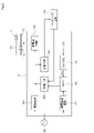
- FIG. 2 is a functional block diagram showing the detailed configuration of the cutoff valve device 3.
- a shut-off valve control circuit 15 corresponding to a control section is composed of, for example, an MCU (Micro Control Unit).
- the power supply circuit 23 is an AC-DC converter that generates, for example, 12 V DC power from the input AC power supply 18 and supplies it to the DC-DC converter 24, the valve driving circuit 25, the charging circuit 26, and the like.
- the DC-DC converter 24 steps down the 12V DC power and supplies the 5V DC power to the cutoff valve control circuit 15 .
- the valve drive circuit 25 outputs a drive signal for opening and closing the shutoff valves 12 and 13 according to the control signal from the shutoff valve control circuit 15 .
- the charging circuit 26 steps down the 12V DC power supply to an appropriate voltage to charge the backup power supply 16 .
- a power failure detection circuit 27 corresponding to a power failure detection unit has, for example, a photocoupler, and its input side is connected to the AC power supply 18 and its output side is connected to the cutoff valve control circuit 15 . If the AC power supply 18 continues to supply power, the output signal from the power failure detection circuit 27 is continuously input to the cutoff valve control circuit 15 accordingly.
- the power supply 18 of the indoor unit 1 and the power supply 18 of the cutoff valve device 3 may be the same commercial AC power supply, or may be separate power supplies. If a separate power source is installed for each of them, it is conceivable that a power failure of the indoor unit 1 and a power failure of the cutoff valve device 3 may occur separately.
- Power is supplied from the backup power supply 16 to the DC 12V line via a discharge circuit 28 , and the discharge circuit 28 is controlled by the cutoff valve control circuit 15 . That is, when power is supplied from the power source 18 to the cutoff valve device 3, the backup power source 16 is charged from the discharge circuit 28. , power supply to the cutoff valve control circuit 15 is started.
- the illustration of the open/close indicator lamp 14 is omitted.
- a remote controller 30 is also connected to the communication bus 17 .
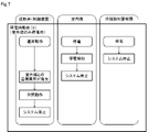
- FIG. 3 to 7 show control sequences among the shutoff valve device 3, the indoor unit 1, and the refrigerant detection alarm device 4.
- FIG. 3 to 7 show control sequences among the shutoff valve device 3, the indoor unit 1, and the refrigerant detection alarm device 4.
- ⁇ Power failure operation (3) (indoor unit 1 only at power failure)>
- the operations of the indoor unit 1 and the refrigerant detector/alarm device 4 are the same as in FIG.
- the shut-off valve device 3 continues "normal operation", but when it detects that the communication with the indoor unit 1 is interrupted, it determines that "communication abnormality has occurred”. Then, the shut-off valves 12 and 13 are closed to shift to "system stop".
- FIG. 8 is a flow chart showing the details of processing in the shutoff valve control circuit 15.
- the cutoff valve control circuit 15 determines whether or not a power cutoff, that is, a power failure has been detected (S1). If no power failure is detected (NO), it is sequentially determined whether communication with the indoor unit 1 has been interrupted (S7) and whether a gas detection signal has been received from the refrigerant detector 4 (S8). If both steps S7 and S8 determine "NO", the shutoff valves 12 and 13 are opened and closed according to instructions from the indoor control circuit 5 of the indoor unit 1, and the flag F is set to the initial value "0" ( S10).
- the process determines whether or not the count value T of the timer T is equal to or greater than the threshold value Ts (S5).
- the threshold Ts corresponds to the above-mentioned "fixed time", and is set to several minutes, for example. If the count value T is less than the threshold value Ts (NO), the process returns to step S1. On the other hand, if the count value T is equal to or greater than the threshold value Ts (YES), the power failure is notified to the indoor unit 1 (S5a), and then the cutoff valves 12 and 13 are closed (S6). Moreover, when (YES) is determined in step S7, the process proceeds to step S6. If (YES) is determined in step S8, the cutoff valves 12 and 13 are also closed to shift to the standby state (S9).
- FIG. 9 is a timing chart corresponding to a case where a power failure that occurs in the AC power supply 18 continues for a certain period of time or more
- FIG. It is a timing chart corresponding to the case.
- the shutoff valve control circuit 15 closes the shutoff valves 12 and 13 immediately, that is, at the timing indicated by the dashed line. (3) the shut-off valve control circuit 15 closes the shut-off valves 12 and 13 at the time (T ⁇ Ts) after a certain period of time has elapsed during the loop of ⁇ S8. Due to this operation, even if the refrigerant leaks during a power failure, it is possible to prevent the amount of refrigerant from leaking into the air-conditioned room in excess of the amount of refrigerant held by the indoor unit 1 .
- the gas sensor 19 of the refrigerant detector 4 detects leakage of the refrigerant used in the refrigeration cycle including the indoor unit 1 and the outdoor unit 27 .
- the shutoff valves 12 and 13 are arranged in the pipes 10 and 11 connecting the indoor unit 1 and the outdoor unit 2, and the power failure detection circuit 27 detects power failure occurring in the AC power supply 18.
- the backup power supply 16 is configured to be able to supply power in place of the AC power supply 18 when a power failure occurs, and the cutoff valve control circuit 15 starts supplying power from the backup power supply 16 when the power failure detection circuit 27 detects a power failure.
- the shutoff valves 12 and 13 are controlled to close. Therefore, when the momentary power failure shown in FIG. 10 occurs, the cutoff valve control circuit 15 does not close the cutoff valves 12 and 13, so that consumption of the backup power supply 16 can be suppressed.
- the shutoff valves 12 and 13 are electronically controlled valves whose opening can be controlled between fully closed and fully opened by being driven by a motor, as in the first embodiment.
- the second embodiment shown in FIG. 11 shows the contents of control when the shut-off valve control circuit 15 performs the "valve opening operation" shown in FIG.
- the shutoff valve control circuit 15 receives an instruction to open the shutoff valve from the indoor unit 1 (S11; YES)
- the shutoff valve control circuit 15 determines whether or not the shutoff valves 12 and 13 are fully open at that time (S12). If not fully open (NO), the remaining battery level H of the backup power source 16 is detected (S13). The remaining battery level H may be calculated by the cutoff valve control circuit 15 .
- the shutoff valve control circuit 15 calculates the valve opening degree X (%) that can be driven until the shutoff valves 12 and 13 are fully closed based on the remaining battery level H (S14). Then, the shutoff valves 12 and 13 are opened until the degree of opening of the shutoff valves 12 and 13 reaches X (%) (S15).
- shutoff valves 12 and 13 are fully open when the power supply 18 is supplying power but the remaining battery level H of the backup power supply 16 is low, a power failure or refrigerant leakage will occur immediately after that.
- the power supply is switched to the power supply from the backup power supply 16
- the cutoff valves 12 and 13 cannot be fully closed due to the power shortage of the backup power supply 16. Therefore, if control is performed as in the second embodiment, the degree of opening of the shutoff valves 12 and 13 is determined according to the remaining battery level H. can be securely closed.
- the shutoff valve is not limited to an electronically controlled valve driven by a motor, and may be any valve that can be opened and closed using electric power. While several embodiments of the invention have been described, these embodiments have been presented by way of example and are not intended to limit the scope of the invention. These novel embodiments can be implemented in various other forms, and various omissions, replacements, and modifications can be made without departing from the scope of the invention. These embodiments and their modifications are included in the scope and gist of the invention, and are included in the scope of the invention described in the claims and equivalents thereof.
Landscapes
- Engineering & Computer Science (AREA)
- Mechanical Engineering (AREA)
- General Engineering & Computer Science (AREA)
- Chemical & Material Sciences (AREA)
- Combustion & Propulsion (AREA)
- Physics & Mathematics (AREA)
- Thermal Sciences (AREA)
- Air Conditioning Control Device (AREA)
Priority Applications (4)
| Application Number | Priority Date | Filing Date | Title |
|---|---|---|---|
| JP2023528887A JP7466061B2 (ja) | 2021-06-17 | 2021-06-17 | 冷凍サイクルの遮断弁制御装置及び空気調和装置 |
| PCT/JP2021/023068 WO2022264368A1 (ja) | 2021-06-17 | 2021-06-17 | 冷凍サイクルの遮断弁制御装置及び空気調和装置 |
| EP21946045.8A EP4357704A4 (en) | 2021-06-17 | 2021-06-17 | STOP VALVE CONTROL DEVICE FOR REFRIGERATION CYCLE AND AIR CONDITIONER |
| US18/275,970 US12474077B2 (en) | 2021-06-17 | 2021-06-17 | Shut-off valve control device for refrigeration cycle, and air conditioner |
Applications Claiming Priority (1)
| Application Number | Priority Date | Filing Date | Title |
|---|---|---|---|
| PCT/JP2021/023068 WO2022264368A1 (ja) | 2021-06-17 | 2021-06-17 | 冷凍サイクルの遮断弁制御装置及び空気調和装置 |
Publications (1)
| Publication Number | Publication Date |
|---|---|
| WO2022264368A1 true WO2022264368A1 (ja) | 2022-12-22 |
Family
ID=84526936
Family Applications (1)
| Application Number | Title | Priority Date | Filing Date |
|---|---|---|---|
| PCT/JP2021/023068 Ceased WO2022264368A1 (ja) | 2021-06-17 | 2021-06-17 | 冷凍サイクルの遮断弁制御装置及び空気調和装置 |
Country Status (4)
| Country | Link |
|---|---|
| US (1) | US12474077B2 (https=) |
| EP (1) | EP4357704A4 (https=) |
| JP (1) | JP7466061B2 (https=) |
| WO (1) | WO2022264368A1 (https=) |
Cited By (5)
| Publication number | Priority date | Publication date | Assignee | Title |
|---|---|---|---|---|
| US11971183B2 (en) | 2019-09-05 | 2024-04-30 | Trane International Inc. | Systems and methods for refrigerant leak detection in a climate control system |
| WO2024201599A1 (ja) * | 2023-03-24 | 2024-10-03 | 東芝キヤリア株式会社 | 空気調和機 |
| US12117191B2 (en) | 2022-06-24 | 2024-10-15 | Trane International Inc. | Climate control system with improved leak detector |
| WO2025109758A1 (ja) * | 2023-11-24 | 2025-05-30 | 三菱電機株式会社 | 空気調和システム、制御装置、および制御方法 |
| US12487008B2 (en) | 2022-01-14 | 2025-12-02 | Trane International Inc. | Method of commissioning an HVAC system |
Families Citing this family (2)
| Publication number | Priority date | Publication date | Assignee | Title |
|---|---|---|---|---|
| WO2023119505A1 (ja) * | 2021-12-22 | 2023-06-29 | 東芝キヤリア株式会社 | 空気調和機 |
| JP2026000652A (ja) | 2024-06-18 | 2026-01-06 | 日本キヤリア株式会社 | 冷媒漏えい検知システム |
Citations (9)
| Publication number | Priority date | Publication date | Assignee | Title |
|---|---|---|---|---|
| JPH0439558A (ja) * | 1990-06-01 | 1992-02-10 | Daikin Ind Ltd | 空気調和装置の運転制御装置 |
| JPH054220U (ja) * | 1991-04-12 | 1993-01-22 | 三菱電機株式会社 | 空気調和機の電源リセツト手段 |
| JPH07280319A (ja) * | 1994-04-07 | 1995-10-27 | Daikin Ind Ltd | 空気調和装置の制御装置 |
| JP2005121333A (ja) * | 2003-10-20 | 2005-05-12 | Hitachi Ltd | 空気調和装置 |
| JP2016031167A (ja) * | 2014-07-28 | 2016-03-07 | ダイキン工業株式会社 | 空調システム |
| WO2018078729A1 (ja) | 2016-10-25 | 2018-05-03 | 三菱電機株式会社 | 冷凍サイクル装置 |
| WO2020110425A1 (ja) * | 2018-11-26 | 2020-06-04 | 日立ジョンソンコントロールズ空調株式会社 | 空気調和システム及び冷媒漏洩防止システム |
| JP2020134005A (ja) | 2019-02-19 | 2020-08-31 | パナソニックIpマネジメント株式会社 | 空気調和装置 |
| WO2021054199A1 (ja) * | 2019-09-19 | 2021-03-25 | ダイキン工業株式会社 | ヒートポンプ装置 |
Family Cites Families (5)
| Publication number | Priority date | Publication date | Assignee | Title |
|---|---|---|---|---|
| JPH0439588A (ja) | 1990-06-05 | 1992-02-10 | Sanden Corp | 冷却ケース用断熱箱の製造方法 |
| US8631663B2 (en) * | 2009-04-30 | 2014-01-21 | Hill Phoenix, Inc. | Power failure controller for an electronically controlled expansion valve in a refrigeration system |
| CH702057A1 (de) * | 2009-10-22 | 2011-04-29 | Belimo Holding Ag | Sicherheitssteuerung für ein Stellglied. |
| US11059352B2 (en) * | 2018-10-31 | 2021-07-13 | Thermo King Corporation | Methods and systems for augmenting a vehicle powered transport climate control system |
| JP2020109343A (ja) * | 2019-01-02 | 2020-07-16 | ダイキン工業株式会社 | 空気調和機および遮断弁 |
-
2021
- 2021-06-17 WO PCT/JP2021/023068 patent/WO2022264368A1/ja not_active Ceased
- 2021-06-17 JP JP2023528887A patent/JP7466061B2/ja active Active
- 2021-06-17 EP EP21946045.8A patent/EP4357704A4/en active Pending
- 2021-06-17 US US18/275,970 patent/US12474077B2/en active Active
Patent Citations (9)
| Publication number | Priority date | Publication date | Assignee | Title |
|---|---|---|---|---|
| JPH0439558A (ja) * | 1990-06-01 | 1992-02-10 | Daikin Ind Ltd | 空気調和装置の運転制御装置 |
| JPH054220U (ja) * | 1991-04-12 | 1993-01-22 | 三菱電機株式会社 | 空気調和機の電源リセツト手段 |
| JPH07280319A (ja) * | 1994-04-07 | 1995-10-27 | Daikin Ind Ltd | 空気調和装置の制御装置 |
| JP2005121333A (ja) * | 2003-10-20 | 2005-05-12 | Hitachi Ltd | 空気調和装置 |
| JP2016031167A (ja) * | 2014-07-28 | 2016-03-07 | ダイキン工業株式会社 | 空調システム |
| WO2018078729A1 (ja) | 2016-10-25 | 2018-05-03 | 三菱電機株式会社 | 冷凍サイクル装置 |
| WO2020110425A1 (ja) * | 2018-11-26 | 2020-06-04 | 日立ジョンソンコントロールズ空調株式会社 | 空気調和システム及び冷媒漏洩防止システム |
| JP2020134005A (ja) | 2019-02-19 | 2020-08-31 | パナソニックIpマネジメント株式会社 | 空気調和装置 |
| WO2021054199A1 (ja) * | 2019-09-19 | 2021-03-25 | ダイキン工業株式会社 | ヒートポンプ装置 |
Non-Patent Citations (1)
| Title |
|---|
| See also references of EP4357704A4 |
Cited By (5)
| Publication number | Priority date | Publication date | Assignee | Title |
|---|---|---|---|---|
| US11971183B2 (en) | 2019-09-05 | 2024-04-30 | Trane International Inc. | Systems and methods for refrigerant leak detection in a climate control system |
| US12487008B2 (en) | 2022-01-14 | 2025-12-02 | Trane International Inc. | Method of commissioning an HVAC system |
| US12117191B2 (en) | 2022-06-24 | 2024-10-15 | Trane International Inc. | Climate control system with improved leak detector |
| WO2024201599A1 (ja) * | 2023-03-24 | 2024-10-03 | 東芝キヤリア株式会社 | 空気調和機 |
| WO2025109758A1 (ja) * | 2023-11-24 | 2025-05-30 | 三菱電機株式会社 | 空気調和システム、制御装置、および制御方法 |
Also Published As
| Publication number | Publication date |
|---|---|
| EP4357704A4 (en) | 2025-04-16 |
| US12474077B2 (en) | 2025-11-18 |
| JPWO2022264368A1 (https=) | 2022-12-22 |
| JP7466061B2 (ja) | 2024-04-11 |
| US20240117989A1 (en) | 2024-04-11 |
| EP4357704A1 (en) | 2024-04-24 |
Similar Documents
| Publication | Publication Date | Title |
|---|---|---|
| JP7466061B2 (ja) | 冷凍サイクルの遮断弁制御装置及び空気調和装置 | |
| US12467670B2 (en) | Heat pump device | |
| JP7407374B2 (ja) | 空気調和装置 | |
| US11118821B2 (en) | Refrigeration cycle apparatus | |
| JPWO2020110425A1 (ja) | 空気調和システム及び冷媒漏洩防止システム | |
| JP2022176373A (ja) | ヒートポンプ装置及び弁キット | |
| JP7769127B2 (ja) | 冷凍サイクル装置 | |
| CN113260822B (zh) | 空调机以及断流阀 | |
| CN104990173B (zh) | 空调器、空调器的防火控制方法、控制器及空调系统 | |
| JP7175936B2 (ja) | ヒートポンプ装置 | |
| JP2002061996A (ja) | 空気調和機 | |
| JP2011058798A (ja) | 空気調和装置 | |
| CN117212933A (zh) | 空调器及其控制方法、控制器和计算机可读存储介质 | |
| JP5655775B2 (ja) | 空気調和装置 | |
| EP4379274A1 (en) | Air conditioner | |
| JP2001304651A (ja) | 空気調和装置及びその運転制御方法 | |
| WO2024042795A1 (ja) | 制御装置、制御装置を備える遮断弁回路、制御装置を備える空気調和装置及び制御方法 | |
| JP3420652B2 (ja) | 空気調和機 | |
| WO2023119506A1 (ja) | 空気調和機 | |
| CN117212968A (zh) | 空调器及其控制方法、控制器和计算机可读存储介质 | |
| JP2011043325A (ja) | 空気調和装置 | |
| JP2024146640A (ja) | 冷媒ガス緊急外部放出システム | |
| CN106500419B (zh) | 一种热泵机组的水路控制系统及其控制方法 | |
| CN119532927A (zh) | 空调的运行监测方法及介质 | |
| CN118935611A (zh) | 防冷媒泄露方法、装置、系统、空调设备和存储介质 |
Legal Events
| Date | Code | Title | Description |
|---|---|---|---|
| 121 | Ep: the epo has been informed by wipo that ep was designated in this application |
Ref document number: 21946045 Country of ref document: EP Kind code of ref document: A1 |
|
| ENP | Entry into the national phase |
Ref document number: 2023528887 Country of ref document: JP Kind code of ref document: A |
|
| WWE | Wipo information: entry into national phase |
Ref document number: 18275970 Country of ref document: US |
|
| WWE | Wipo information: entry into national phase |
Ref document number: 2021946045 Country of ref document: EP |
|
| NENP | Non-entry into the national phase |
Ref country code: DE |
|
| ENP | Entry into the national phase |
Ref document number: 2021946045 Country of ref document: EP Effective date: 20240117 |
|
| WWG | Wipo information: grant in national office |
Ref document number: 18275970 Country of ref document: US |