WO2022264368A1 - Shut-off valve control device for refrigeration cycle, and air conditioner - Google Patents

Shut-off valve control device for refrigeration cycle, and air conditioner Download PDF

Info

Publication number
WO2022264368A1
WO2022264368A1 PCT/JP2021/023068 JP2021023068W WO2022264368A1 WO 2022264368 A1 WO2022264368 A1 WO 2022264368A1 JP 2021023068 W JP2021023068 W JP 2021023068W WO 2022264368 A1 WO2022264368 A1 WO 2022264368A1
Authority
WO
WIPO (PCT)
Prior art keywords
power failure
valve
shut
power
indoor unit
Prior art date
Application number
PCT/JP2021/023068
Other languages
French (fr)
Japanese (ja)
Inventor
充 澤村
Original Assignee
東芝キヤリア株式会社
Priority date (The priority date is an assumption and is not a legal conclusion. Google has not performed a legal analysis and makes no representation as to the accuracy of the date listed.)
Filing date
Publication date
Application filed by 東芝キヤリア株式会社 filed Critical 東芝キヤリア株式会社
Priority to PCT/JP2021/023068 priority Critical patent/WO2022264368A1/en
Priority to EP21946045.8A priority patent/EP4357704A1/en
Priority to US18/275,970 priority patent/US20240117989A1/en
Priority to JP2023528887A priority patent/JP7466061B2/en
Publication of WO2022264368A1 publication Critical patent/WO2022264368A1/en

Links

Images

Classifications

    • FMECHANICAL ENGINEERING; LIGHTING; HEATING; WEAPONS; BLASTING
    • F24HEATING; RANGES; VENTILATING
    • F24FAIR-CONDITIONING; AIR-HUMIDIFICATION; VENTILATION; USE OF AIR CURRENTS FOR SCREENING
    • F24F11/00Control or safety arrangements
    • F24F11/88Electrical aspects, e.g. circuits
    • FMECHANICAL ENGINEERING; LIGHTING; HEATING; WEAPONS; BLASTING
    • F24HEATING; RANGES; VENTILATING
    • F24FAIR-CONDITIONING; AIR-HUMIDIFICATION; VENTILATION; USE OF AIR CURRENTS FOR SCREENING
    • F24F11/00Control or safety arrangements
    • F24F11/30Control or safety arrangements for purposes related to the operation of the system, e.g. for safety or monitoring
    • F24F11/32Responding to malfunctions or emergencies
    • F24F11/36Responding to malfunctions or emergencies to leakage of heat-exchange fluid
    • FMECHANICAL ENGINEERING; LIGHTING; HEATING; WEAPONS; BLASTING
    • F24HEATING; RANGES; VENTILATING
    • F24FAIR-CONDITIONING; AIR-HUMIDIFICATION; VENTILATION; USE OF AIR CURRENTS FOR SCREENING
    • F24F11/00Control or safety arrangements
    • F24F11/70Control systems characterised by their outputs; Constructional details thereof
    • F24F11/80Control systems characterised by their outputs; Constructional details thereof for controlling the temperature of the supplied air
    • F24F11/83Control systems characterised by their outputs; Constructional details thereof for controlling the temperature of the supplied air by controlling the supply of heat-exchange fluids to heat-exchangers
    • F24F11/84Control systems characterised by their outputs; Constructional details thereof for controlling the temperature of the supplied air by controlling the supply of heat-exchange fluids to heat-exchangers using valves
    • FMECHANICAL ENGINEERING; LIGHTING; HEATING; WEAPONS; BLASTING
    • F25REFRIGERATION OR COOLING; COMBINED HEATING AND REFRIGERATION SYSTEMS; HEAT PUMP SYSTEMS; MANUFACTURE OR STORAGE OF ICE; LIQUEFACTION SOLIDIFICATION OF GASES
    • F25BREFRIGERATION MACHINES, PLANTS OR SYSTEMS; COMBINED HEATING AND REFRIGERATION SYSTEMS; HEAT PUMP SYSTEMS
    • F25B49/00Arrangement or mounting of control or safety devices
    • F25B49/02Arrangement or mounting of control or safety devices for compression type machines, plants or systems

Abstract

A shut-off valve control device for a refrigeration cycle according to an embodiment of the present invention comprises: a leakage detection unit that detects leakage of a cooling medium which is used in a refrigeration cycle including an indoor unit and an outdoor unit; a shut-off valve that is disposed to a pipe which connects the indoor unit with the outdoor unit and that can be opened and closed by supply of electric power; a power failure detection unit that detects power failure in an AC power source which supplies electric power to the shut-off valve; a backup power source that is configured to alternatively supply power when power failure has occurred; and a shut-off valve control circuit that controls the shut-off valve to be closed when the leakage detection unit has detected leakage of the cooling medium, wherein when the power failure detection unit has detected power failure, the shut-off valve control circuit causes the backup power source to start to supply power and, when the power failure detection unit continues to detect power failure even after a predetermined time period has elapsed, the shut-off valve control circuit controls the shut-off valve to be closed.

Description

冷凍サイクルの遮断弁制御装置及び空気調和装置Shutoff valve control device for refrigeration cycle and air conditioner
 本発明の実施形態は、空気調和装置などの冷凍サイクルに使用されている冷媒の屋内への漏洩を検知すると、その屋内に設置された室内機に繋がる配管中に設けた遮断弁を閉じる装置に関する。 An embodiment of the present invention relates to a device that closes a shut-off valve provided in a pipe connected to an indoor unit installed indoors when leakage of a refrigerant used in a refrigeration cycle of an air conditioner or the like into the room is detected. .
 例えばR32のようなA2L冷媒を使用する冷凍サイクル装置については、IEC60335において安全を図る目的で、冷媒の漏洩を検知する機器と、冷媒の漏洩を止めるための遮断弁又は換気扇とを備え、停電中に冷媒の漏洩が発生してもその漏洩量を最小限とするために、上記の遮断弁を閉じることが要求されている。このような安全装置においては、停電発生時には冷媒の漏洩が検知できないため、例えば特許文献1,2には、冷凍サイクル装置に予備電源を備え、停電発生時には、この予備電源によって遮断弁を閉じることが記載されている。 For example, for refrigeration cycle equipment using A2L refrigerant such as R32, for the purpose of ensuring safety in IEC60335, it is equipped with a device to detect leakage of refrigerant and a shutoff valve or ventilation fan to stop leakage of refrigerant. In order to minimize the amount of refrigerant leakage, it is required to close the shutoff valve. In such a safety device, refrigerant leakage cannot be detected in the event of a power failure. is described.
WO2018/078729号WO2018/078729 特開2020-134005号公報Japanese Patent Application Laid-Open No. 2020-134005
 しかしながら、上記の特許文献には予備電源を備えることのみしか記載がなく、停電時にどのような手順によって開閉弁を全閉するかについては、具体的な記載がない。冷凍サイクル装置のように各々の構成部が個別に電源に接続される装置の停電には様々な発生態様や発生個所があることから、停電の発生を検知した場合でも、直ちに開閉弁を閉じる制御を行う必要が無いこともあり得る。また、バッテリ等の予備電源は、無尽蔵に電力を供給できるわけではなく、実際に冷媒が漏洩した時に遮断弁を閉じるために、普段は極力電力を消費しない状態にしておく必要がある。
 そこで、状況に対応して適切に開閉弁を閉じる制御を行うことができる冷凍サイクルの遮断弁制御装置及び空気調和装置を提供する。
However, the above patent document only describes provision of a standby power supply, and does not specifically describe by what procedure the on-off valve is to be fully closed in the event of a power failure. Since there are various modes and locations of power failures in equipment such as refrigeration cycle equipment, in which each component is individually connected to a power supply, even if a power failure is detected, control to close the on-off valve immediately. may not need to be done. In addition, a standby power source such as a battery cannot supply power indefinitely, and in order to close the cutoff valve when the refrigerant actually leaks, it is necessary to keep power consumption as low as possible.
Therefore, a refrigeration cycle shut-off valve control device and an air conditioner are provided that are capable of appropriately controlling the closing of the on-off valve according to the situation.
 実施形態の冷凍サイクルの遮断弁制御装置は、室内機及び室外機を含む冷凍サイクルに使用されている冷媒の漏洩を検知する漏洩検知部と、
 前記室内機と前記室外機との間を接続する配管に配置され、電力を供給することで開閉可能な遮断弁と、
 この遮断弁に電力を供給する交流電源の停電を検知する停電検知部と、
 前記停電の発生時に代替して電源を供給可能に構成されるバックアップ電源と、
 前記漏洩検知部が冷媒の漏洩を検知すると、前記遮断弁を閉に制御する遮断弁制御回路とを備え、
 前記遮断弁制御回路は、前記停電検知部が一定時間の間停電の検知を継続している際に、前記遮断弁を閉じるように制御する。
 また、実施形態の空気調和装置は、室内に設置される室内機と、
室外機と、
 前記室内機が設置される室内に設置され、前記室内機と前記室外機からなる冷凍サイクルに使用されている冷媒の漏洩を検知する漏洩検知部と、
 前記室内機と前記室外機との間を接続する配管の途中に設けられ、電力により前記室内機と前記室外機の間の冷媒の流れを開放もしくは遮断する遮断弁を備えた遮断弁装置とを備え、
 前記遮断弁装置は、前記遮断弁に電力を供給する交流電源の停電を検知する停電検知部と、
 前記停電の発生時に代替して前記遮断弁に電力を供給可能なバックアップ電源と、
 前記漏洩検知部が冷媒の漏洩を検知すると前記遮断弁を閉に制御し、前記停電検知部が一定時間の間停電の検知を継続している際に、前記遮断弁を閉じるように制御する遮断弁制御回路とを備える。
A shutoff valve control device for a refrigeration cycle according to an embodiment includes a leakage detection unit that detects leakage of a refrigerant used in a refrigeration cycle including an indoor unit and an outdoor unit;
A shut-off valve arranged in a pipe connecting between the indoor unit and the outdoor unit and capable of being opened and closed by supplying electric power;
A power failure detection unit that detects a power failure of the AC power supply that supplies power to the shutoff valve;
a backup power supply configured to be able to supply power as an alternative in the event of a power failure;
a shut-off valve control circuit that controls the shut-off valve to close when the leakage detection unit detects refrigerant leakage,
The shut-off valve control circuit controls to close the shut-off valve when the power failure detection unit continues to detect power failure for a certain period of time.
Further, the air conditioner of the embodiment includes an indoor unit installed indoors,
outdoor unit and
a leakage detection unit that is installed in a room where the indoor unit is installed and detects leakage of a refrigerant used in a refrigeration cycle composed of the indoor unit and the outdoor unit;
a shutoff valve device provided in the middle of a pipe connecting between the indoor unit and the outdoor unit, and equipped with a shutoff valve for opening or shutting off the flow of refrigerant between the indoor unit and the outdoor unit by electric power. prepared,
The shutoff valve device includes a power failure detection unit that detects a power failure of an AC power supply that supplies power to the shutoff valve;
a backup power supply capable of alternatively supplying power to the cutoff valve when the power failure occurs;
When the leakage detection unit detects refrigerant leakage, the shutoff valve is controlled to close, and when the power failure detection unit continues to detect a power failure for a certain period of time, the shutoff is controlled to close the shutoff valve. and a valve control circuit.
図1は、第1実施形態であり、冷凍サイクルシステムの構成を示す図である。FIG. 1 is a diagram showing the configuration of a refrigeration cycle system according to the first embodiment. 図2は、遮断弁制御装置の詳細な構成を示す機能ブロック図である。FIG. 2 is a functional block diagram showing the detailed configuration of the shutoff valve control device. 図3は、遮断弁制御装置,室内機及び冷媒検知警報器間における制御シーケンスであり、定常動作を示す図である。FIG. 3 shows a control sequence among the shut-off valve control device, the indoor unit, and the refrigerant detector, and shows steady operation. 図4は、同冷媒漏洩動作を示す図である。FIG. 4 is a diagram showing the refrigerant leakage operation. 図5は、同停電時動作(1)を示す図である。FIG. 5 is a diagram showing operation (1) at the time of power failure. 図6は、同停電時動作(2)を示す図である。FIG. 6 is a diagram showing operation (2) at the time of power failure. 図7は、同停電時動作(3)を示す図である。FIG. 7 is a diagram showing operation (3) at the time of power failure. 図8は、遮断弁制御装置の制御回路における処理内容を示すフローチャートである。FIG. 8 is a flow chart showing the contents of processing in the control circuit of the shut-off valve control device. 図9は、交流電源に発生した停電が一定時間以上継続する場合に対応したタイミングチャートである。FIG. 9 is a timing chart corresponding to a case where a power failure occurring in an AC power supply continues for a certain period of time or longer. 図10は、交流電源に瞬停が発生した場合に対応したタイミングチャートである。FIG. 10 is a timing chart corresponding to the momentary blackout of the AC power supply. 図11は、第2実施形態であり、遮断弁制御装置の制御回路が図3に示す「弁開動作」を行う場合の制御内容を示すフローチャートである。FIG. 11 is a second embodiment, and is a flow chart showing the contents of control when the control circuit of the shut-off valve control device performs the "valve opening operation" shown in FIG.
  (第1実施形態)
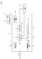
 図1に示すように、本実施形態の冷凍サイクル装置は、例えば、屋内に設置される室内機1,屋外に設置する室外機2,これらを接続する冷媒配管10、11からなる空気調和装置である。この空気調和装置は、さらに、冷媒配管10、11の途中に介在する遮断弁装置3及び冷媒検知警報器4を備えている。室内機1は、室内制御回路5,ファン6,熱交換器7及び開閉弁8を有しており、室内制御回路5は、室内熱交換器に通風するファン6及び冷媒の流通を切り替える開閉弁8を制御する。また、室内制御回路5は、通信ライン9を介して屋外の室外機2の図示しない室外制御回路と通信を行う。なお、遮断弁装置3は室内機1内に組み込むことも可能であるが、組み込んだ場合、室内機1が大型化してしまう。このため、遮断弁装置3は、室内機1近傍の天井裏や床下に設置することが望ましい。
(First embodiment)
As shown in FIG. 1, the refrigeration cycle apparatus of the present embodiment is an air conditioner comprising, for example, an indoor unit 1 installed indoors, an outdoor unit 2 installed outdoors, and refrigerant pipes 10 and 11 connecting these units. be. This air conditioner further includes a shutoff valve device 3 and a refrigerant detection alarm device 4 interposed in the refrigerant pipes 10 and 11 . The indoor unit 1 has an indoor control circuit 5, a fan 6, a heat exchanger 7, and an on-off valve 8. The indoor control circuit 5 includes a fan 6 for ventilating the indoor heat exchanger and an on-off valve for switching the circulation of the refrigerant. 8 is controlled. The indoor control circuit 5 also communicates with an outdoor control circuit (not shown) of the outdoor unit 2 through a communication line 9 . The shut-off valve device 3 can be incorporated in the indoor unit 1, but if it is incorporated, the size of the indoor unit 1 will be increased. Therefore, it is desirable to install the shut-off valve device 3 in the ceiling or under the floor near the indoor unit 1 .
 室内機1の熱交換器7は、液側の配管10及びガス側の配管11を介して室外機2に接続されており、この配管中を冷媒が流通することで冷凍サイクルが形成される。室内機1の開閉弁8は、液側となる配管10側に配置されている。また、室内機1と室外機2との間の配管10及び11には、遮断弁装置3が介在している。室内機1からは配管10により、例えばR32のような冷媒液が室外機2に送出され、室外機2からは配管11により、冷媒液が高圧ガス化したものが室内機1に戻る。なお、複数の室内機1が1台の室外機2の冷媒配管に並列に接続されるいわゆるマルチタイプで、且つ、各室内機1の暖房と冷房との組み合わせを自由に選択できる冷暖同時マルチエアコンに適用する場合は、室内機1と室外機3が3本の配管によって接続されるため、遮断弁12,13に加えて3本目の配管途中にも遮断弁を設ける必要がある。 The heat exchanger 7 of the indoor unit 1 is connected to the outdoor unit 2 via a liquid-side pipe 10 and a gas-side pipe 11, and refrigerant flows through these pipes to form a refrigeration cycle. The on-off valve 8 of the indoor unit 1 is arranged on the pipe 10 side, which is the liquid side. In addition, a cutoff valve device 3 is interposed between the pipes 10 and 11 between the indoor unit 1 and the outdoor unit 2 . From the indoor unit 1 , a refrigerant liquid such as R32 is sent to the outdoor unit 2 through the pipe 10 , and from the outdoor unit 2 , the high-pressure gasified refrigerant liquid returns to the indoor unit 1 through the pipe 11 . In addition, it is a so-called multi-type air conditioner in which a plurality of indoor units 1 are connected in parallel to the refrigerant pipe of one outdoor unit 2, and the combination of heating and cooling of each indoor unit 1 can be freely selected. , the indoor unit 1 and the outdoor unit 3 are connected by three pipes, so in addition to the shutoff valves 12 and 13, it is necessary to provide a shutoff valve in the middle of the third pipe.
 遮断弁装置3は、配管10及び11にそれぞれ介在する遮断弁12及び13,開閉表示ランプ14,これらを制御する遮断弁制御回路15及びバックアップ電源16を備えている。遮断弁制御回路15は、通信バス17を介して室内機1の室内制御回路5に接続されており、両者間で通信が行われる。バックアップ電源16は、例えばリチウム電池のような二次電池やスーパーキャパシタ等で構成されている。バックアップ電源16は、常には遮断弁装置3が接続されている交流電源18より充電が行われており、交流電源18に停電が発生した際に遮断弁装置3を動作させるために使用される。開閉表示ランプ14は、遮断弁12及び13の開閉状態に応じて点消灯状態が制御される。遮断弁12及び13は、モータ駆動により弁の開閉を制御する電子制御弁、いわゆるパルスモータバルブ(PMV)である。なお、開閉弁8も同様の電子制御弁を使用することができる。 The shutoff valve device 3 includes shutoff valves 12 and 13 interposed in the pipes 10 and 11, respectively, an open/close indicator lamp 14, a shutoff valve control circuit 15 for controlling these, and a backup power supply 16. The shut-off valve control circuit 15 is connected to the indoor control circuit 5 of the indoor unit 1 via a communication bus 17, and communication is performed between them. The backup power supply 16 is composed of, for example, a secondary battery such as a lithium battery, a supercapacitor, or the like. The backup power supply 16 is always charged by the AC power supply 18 to which the cutoff valve device 3 is connected, and is used to operate the cutoff valve device 3 when a power failure occurs in the AC power supply 18. The on/off state of the open/close indicator lamp 14 is controlled according to the open/close state of the cutoff valves 12 and 13 . The shut-off valves 12 and 13 are electronic control valves, so-called pulse motor valves (PMV), which control opening and closing of the valves by motor drive. A similar electronic control valve can be used as the on-off valve 8 as well.
 漏洩検知部に相当する冷媒検知警報器4は、空気中の所定濃度の冷媒を検知するガスセンサ19,警報ランプ20,警報ブザー21,検知状態解除スイッチ22及び室内機1と通信を行うための図示しない制御回路を備えている。ガスセンサ19は、配管10又は11よりガス化した冷媒が漏出した際にそのガスを検知すると漏洩検知信号を出力する。これにより、警報ランプ20を点灯させると共に、警報ブザー21を鳴動させる。また、冷媒検知警報器4も通信バス17に接続されており、上記制御回路は、漏洩検知信号を室内機1の室内制御回路5に出力する。尚、通信バス17は電源ラインも備えており、冷媒検知警報器4は、室内機1より通信バス17を介して動作用の電源供給を受けている。冷媒検知警報器4は、一般に室内機1が設置された被空調室内に設置される。なお、室内機1の内部に冷媒検知警報器4を組み込んでも良い。 A refrigerant detection alarm device 4 corresponding to a leakage detection unit includes a gas sensor 19 for detecting a predetermined concentration of refrigerant in the air, an alarm lamp 20, an alarm buzzer 21, a detection state cancellation switch 22, and an indoor unit 1 for communication. It has a control circuit that does not The gas sensor 19 outputs a leakage detection signal when detecting gas when the gasified refrigerant leaks from the pipe 10 or 11 . As a result, the alarm lamp 20 is lit and the alarm buzzer 21 is sounded. The refrigerant detection alarm device 4 is also connected to the communication bus 17 , and the control circuit outputs a leakage detection signal to the indoor control circuit 5 of the indoor unit 1 . The communication bus 17 also includes a power supply line, and the refrigerant detector/alarm device 4 receives power supply for operation from the indoor unit 1 via the communication bus 17 . The refrigerant detector 4 is generally installed in the air-conditioned room in which the indoor unit 1 is installed. Note that the refrigerant detector 4 may be incorporated inside the indoor unit 1 .
 図2は、遮断弁装置3の詳細な構成を示す機能ブロック図である。制御部に相当する遮断弁制御回路15は、例えばMCU(Micro Control Unit)で構成されている。電源回路23はAC-DCコンバータであり、入力される交流電源18より例えば12Vの直流電源を生成して、DC-DCコンバータ24,弁駆動回路25及び充電回路26等に供給する。DC-DCコンバータ24は、12Vの直流電源を降圧して生成した5Vの直流電源を遮断弁制御回路15に供給する。 FIG. 2 is a functional block diagram showing the detailed configuration of the cutoff valve device 3. As shown in FIG. A shut-off valve control circuit 15 corresponding to a control section is composed of, for example, an MCU (Micro Control Unit). The power supply circuit 23 is an AC-DC converter that generates, for example, 12 V DC power from the input AC power supply 18 and supplies it to the DC-DC converter 24, the valve driving circuit 25, the charging circuit 26, and the like. The DC-DC converter 24 steps down the 12V DC power and supplies the 5V DC power to the cutoff valve control circuit 15 .
 弁駆動回路25は、遮断弁制御回路15からの制御信号に応じて、遮断弁12及び13を開閉駆動するための駆動信号を出力する。充電回路26は、12Vの直流電源を適正な電圧に降圧してバックアップ電源16を充電する。停電検知部に相当する停電検知回路27は、例えばフォトカプラを有しており、その入力側は交流電源18に接続され、出力側は遮断弁制御回路15に接続されている。交流電源18が電源の供給を継続していれば、それに伴い遮断弁制御回路15には、停電検知回路27からの出力信号が継続的に入力される。交流電源18に停電が発生すると、遮断弁制御回路15には上記出力信号の入力が停止されるので、それが停電検知信号となり、遮断弁制御回路15には割込み信号として入力される。ここで、室内機1の電源18と遮断弁装置3の電源18は同じ商用交流電源でも良いし、別電源でも良い。それぞれに別電源を敷設した場合には、室内機1の停電と遮断弁装置3も停電が個別に発生する事態も想定される。 The valve drive circuit 25 outputs a drive signal for opening and closing the shutoff valves 12 and 13 according to the control signal from the shutoff valve control circuit 15 . The charging circuit 26 steps down the 12V DC power supply to an appropriate voltage to charge the backup power supply 16 . A power failure detection circuit 27 corresponding to a power failure detection unit has, for example, a photocoupler, and its input side is connected to the AC power supply 18 and its output side is connected to the cutoff valve control circuit 15 . If the AC power supply 18 continues to supply power, the output signal from the power failure detection circuit 27 is continuously input to the cutoff valve control circuit 15 accordingly. When a power failure occurs in the AC power supply 18, the input of the output signal to the shutoff valve control circuit 15 is stopped, so that it becomes a power failure detection signal and is input to the shutoff valve control circuit 15 as an interrupt signal. Here, the power supply 18 of the indoor unit 1 and the power supply 18 of the cutoff valve device 3 may be the same commercial AC power supply, or may be separate power supplies. If a separate power source is installed for each of them, it is conceivable that a power failure of the indoor unit 1 and a power failure of the cutoff valve device 3 may occur separately.
 バックアップ電源16から直流12Vラインへの電源供給は放電回路28を介して行われ、放電回路28は、遮断弁制御回路15により制御される。すなわち、電源18から遮断弁装置3に対して電力供給があれば放電回路28からバックアップ電源16に充電が行われ、電源18が停電等で遮断弁装置3への電力供給が停止するとバックアップ電源16から遮断弁制御回路15に対する給電が開始される。尚、開閉表示ランプ14の図示は省略している。また、通信バス17には、リモコン30が接続されている。 Power is supplied from the backup power supply 16 to the DC 12V line via a discharge circuit 28 , and the discharge circuit 28 is controlled by the cutoff valve control circuit 15 . That is, when power is supplied from the power source 18 to the cutoff valve device 3, the backup power source 16 is charged from the discharge circuit 28. , power supply to the cutoff valve control circuit 15 is started. The illustration of the open/close indicator lamp 14 is omitted. A remote controller 30 is also connected to the communication bus 17 .
 次に、本実施形態の作用について図3から図10を参照して説明する。図3から図7は、遮断弁装置3,室内機1及び冷媒検知警報器4間における制御シーケンスを示す。 Next, the action of this embodiment will be described with reference to FIGS. 3 to 10. FIG. 3 to 7 show control sequences among the shutoff valve device 3, the indoor unit 1, and the refrigerant detection alarm device 4. FIG.
  <定常動作>
 図3に示す定常動作では、各機器に交流電源18が投入されて起動すると、通信バス17を介して室内機1及び遮断弁装置3間と、室内機1及び冷媒検知警報器4間との間で「初期通信」が行われる。その後、遮断弁装置3は、「弁初期動作」として遮断弁12及び13を閉じるが、室内機1より「弁開指令」を受信すると、遮断弁12及び13を開く。冷媒検知警報器4は、室内機1に冷媒漏洩検知の有無を通知する「状態送信定期通信」を行う。
<Regular operation>
In the steady operation shown in FIG. 3 , when the AC power supply 18 is turned on and each device is activated, communication between the indoor unit 1 and the shutoff valve device 3 and between the indoor unit 1 and the refrigerant detection alarm device 4 is established via the communication bus 17. An "initial communication" takes place between Thereafter, the shut-off valve device 3 closes the shut-off valves 12 and 13 as the “valve initial operation”, but opens the shut-off valves 12 and 13 when receiving the “valve open command” from the indoor unit 1 . The refrigerant detection/alarm device 4 performs “periodic state transmission communication” for notifying the indoor unit 1 of detection of refrigerant leakage.
  <冷媒漏洩動作>
 図4に示す冷媒漏洩動作では、冷媒検知警報器4が冷媒の漏洩を検知すると、検知したことを室内機1に通知するため通信バス17を介して「冷媒漏洩送信」を行う。室内機1は、その通知を受信すると、遮断弁装置3に「弁閉指令」を送信する。遮断弁装置3は「弁閉指令」を受信すると、遮断弁12及び13を閉じる。これらの動作によって、室内機1は冷凍サイクルから切り離され、室内機1内に存在する以上の量の冷媒は被空調室内に漏洩しなくなる。冷媒は主として室外機2に大量に保有されるため、室内に漏洩する冷媒が室内機1の内部に保有する冷媒のみであれば、室内への大量の冷媒漏洩は防止できる。
<Refrigerant leakage operation>
In the refrigerant leakage operation shown in FIG. 4, when the refrigerant detection/alarm device 4 detects refrigerant leakage, "refrigerant leakage transmission" is performed via the communication bus 17 to notify the indoor unit 1 of the detection. Upon receiving the notification, the indoor unit 1 transmits a “valve closing command” to the shutoff valve device 3 . The shut-off valve device 3 closes the shut-off valves 12 and 13 upon receiving the "valve closing command". By these operations, the indoor unit 1 is disconnected from the refrigerating cycle, and the amount of refrigerant in the indoor unit 1 or more does not leak into the air-conditioned room. Since a large amount of refrigerant is mainly stored in the outdoor unit 2, if the only refrigerant that leaks indoors is the refrigerant stored inside the indoor unit 1, a large amount of refrigerant can be prevented from leaking indoors.
  <停電時動作(1)(全機器停電時)>
 図5に示す停電時動作(1)では、冷媒検知警報器4は直ちに「システム停止」となる。室内機1は「停電検知」してから「システム停止」となる。遮断弁装置3では、停電検知回路27により「停電検知」が行われ、遮断弁制御回路15は放電回路28を介してバックアップ電源16からの給電をONにする。その後、「一定時間経過待ち」をしてから遮断弁12及び13を閉じる。
<Action during power failure (1) (when all equipment is powered off)>
In the power failure operation (1) shown in FIG. 5, the refrigerant detection alarm 4 immediately becomes "system stop". The indoor unit 1 becomes "system stop" after "power failure detection". In the shut-off valve device 3 , “power failure detection” is performed by the power failure detection circuit 27 , and the shut-off valve control circuit 15 turns on power supply from the backup power source 16 via the discharge circuit 28 . After that, after "waiting for the elapse of a certain period of time", the cutoff valves 12 and 13 are closed.
  <停電時動作(2)(装置3のみ停電時)>
 図6に示す停電時動作(2)では、遮断弁装置3の動作は図5と同じであるが、遮断弁制御回路15は、バックアップ電源16からの給電により動作している期間は、室内機1との通信を停止する。室内機1及び冷媒検知警報器4は「通常動作」を継続するが、室内機1は、遮断弁装置3との通信が途絶したことを検知すると「通信異常発生」と判断する。そして、「異常発報」を行うと「システム停止」に移行する。それに伴い、ステータスが「システム停止」となっていることを冷媒検知警報器4に送信し、冷媒検知警報器4も「システム停止」となる。
<Operation at power failure (2) (only device 3 at power failure)>
In the power failure operation (2) shown in FIG. 6, the operation of the shutoff valve device 3 is the same as in FIG. Stop communication with 1. The indoor unit 1 and the refrigerant detection/alarm device 4 continue "normal operation", but the indoor unit 1 determines that "communication abnormality has occurred" when it detects that communication with the cutoff valve device 3 has been interrupted. Then, when the "abnormality report" is performed, the process shifts to "system stop". Along with this, it transmits to the refrigerant detection/alarm device 4 that the status is "system stopped", and the refrigerant detection/alarm device 4 also becomes "system stopped".
  <停電時動作(3)(室内機1のみ停電時)>
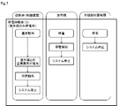
 図7に示す停電時動作(3)では、室内機1及び冷媒検知警報器4の動作は図5と同じである。遮断弁装置3は「通常動作」を継続するが、室内機1との通信が途絶したことを検知すると「通信異常発生」と判断する。すると、遮断弁12及び13を閉じて「システム停止」に移行する。
<Power failure operation (3) (indoor unit 1 only at power failure)>
In the power failure operation (3) shown in FIG. 7, the operations of the indoor unit 1 and the refrigerant detector/alarm device 4 are the same as in FIG. The shut-off valve device 3 continues "normal operation", but when it detects that the communication with the indoor unit 1 is interrupted, it determines that "communication abnormality has occurred". Then, the shut-off valves 12 and 13 are closed to shift to "system stop".
 図8は、遮断弁制御回路15における処理内容を示すフローチャートである。遮断弁制御回路15は、電源遮断,つまり停電を検知したか否かを判断する(S1)。停電を検知しなければ(NO)、室内機1との通信が途絶したか否か(S7)、冷媒検知警報器4よりガス検知信号を受信したか否か(S8)を順次判断する。ステップS7及びS8で何れも「NO」と判断すると、室内機1の室内制御回路5からの指示に従い遮断弁12及び13を開閉して、フラグFを初期値である「0」にセットする(S10)。 FIG. 8 is a flow chart showing the details of processing in the shutoff valve control circuit 15. FIG. The cutoff valve control circuit 15 determines whether or not a power cutoff, that is, a power failure has been detected (S1). If no power failure is detected (NO), it is sequentially determined whether communication with the indoor unit 1 has been interrupted (S7) and whether a gas detection signal has been received from the refrigerant detector 4 (S8). If both steps S7 and S8 determine "NO", the shutoff valves 12 and 13 are opened and closed according to instructions from the indoor control circuit 5 of the indoor unit 1, and the flag F is set to the initial value "0" ( S10).
 ステップS1で電源遮断を検知すると(YES)、「F=0」か否かを判断する(S2)。「F=0」であれば(YES)「F=1」にセットしてから、停電状態が継続していることを確認するために用いるタイマTによるカウントをスタートさせて(S3)、タイマTのカウントを行う(S4)。 When the power shutdown is detected in step S1 (YES), it is determined whether "F=0" (S2). If "F = 0" (YES), set "F = 1", then start counting by the timer T used to confirm that the power failure state continues (S3). is counted (S4).
 続いて、タイマTのカウント値Tが閾値Ts以上か否かを判断する(S5)。閾値Tsは前記の「一定時間」に相当し、例えば数分程度に設定する。カウント値Tが閾値Ts未満であれば(NO)、ステップS1に戻る。一方、カウント値Tが閾値Ts以上であれば(YES)、室内機1に対して停電を報知して(S5a)から、遮断弁12及び13を閉じる(S6)。また、ステップS7で(YES)と判断した場合もステップS6に移行する。ステップS8で(YES)と判断した場合は、やはり遮断弁12及び13を閉じて待機状態に移行する(S9)。 Then, it is determined whether or not the count value T of the timer T is equal to or greater than the threshold value Ts (S5). The threshold Ts corresponds to the above-mentioned "fixed time", and is set to several minutes, for example. If the count value T is less than the threshold value Ts (NO), the process returns to step S1. On the other hand, if the count value T is equal to or greater than the threshold value Ts (YES), the power failure is notified to the indoor unit 1 (S5a), and then the cutoff valves 12 and 13 are closed (S6). Moreover, when (YES) is determined in step S7, the process proceeds to step S6. If (YES) is determined in step S8, the cutoff valves 12 and 13 are also closed to shift to the standby state (S9).
 図9は、交流電源18に発生した停電が一定時間以上継続する場合に対応したタイミングチャートであり、図10は、発生した停電が一定時間内に解消されて復帰する、所謂瞬停が発生した場合に対応したタイミングチャートである。図9に示すように、(1)交流電源18に停電が発生したことを検知すると、(2)遮断弁制御回路15は放電回路28を介してバックアップ電源16からの給電を開始させる。これにより12V電源の電圧は迅速に復帰する。 FIG. 9 is a timing chart corresponding to a case where a power failure that occurs in the AC power supply 18 continues for a certain period of time or more, and FIG. It is a timing chart corresponding to the case. As shown in FIG. 9, (1) when a power failure of the AC power supply 18 is detected, (2) the cutoff valve control circuit 15 starts supplying power from the backup power supply 16 via the discharge circuit 28 . As a result, the voltage of the 12V power supply recovers quickly.
 ここで、従来は停電を検知しているので、遮断弁制御回路15が即座に、すなわち破線で示すタイミングで遮断弁12及び13を閉じることになるが、本実施形態では、図8におけるステップS1~S8のループを回っている間に一定時間が経過して(T≧Ts)になった際に、その時点で(3)遮断弁制御回路15は遮断弁12及び13を閉じる。この動作によって、万が一、停電時に冷媒が漏洩しても、被空調室に対して室内機1の保有する冷媒量以上の漏洩は防止できる。 Here, since a power failure is conventionally detected, the shutoff valve control circuit 15 closes the shutoff valves 12 and 13 immediately, that is, at the timing indicated by the dashed line. (3) the shut-off valve control circuit 15 closes the shut-off valves 12 and 13 at the time (T≧Ts) after a certain period of time has elapsed during the loop of ˜S8. Due to this operation, even if the refrigerant leaks during a power failure, it is possible to prevent the amount of refrigerant from leaking into the air-conditioned room in excess of the amount of refrigerant held by the indoor unit 1 .
 一方、図10に示す極めて短時間の瞬時停電、いわゆる瞬停、の発生時には、この一定時間が経過する以前に(3)交流電源18からの電源供給が復帰しているので、遮断弁制御回路15は遮断弁12及び13を閉じる動作を実行しない。例えば、遮断弁制御回路15のみが動作している場合の消費電流値は10mA程度であるのに対し、遮断弁12及び13を開閉させる際の消費電流値は500mA程度である。したがって、一定時間の間に遮断弁制御回路15のみを動作させたとしても、遮断弁12及び13を閉じる動作を実行させなければ電力消費は小さくなるので、バックアップ電源16の消耗を抑制できる。 On the other hand, when an extremely short momentary power failure shown in FIG. 10, a so-called instantaneous power failure, occurs, (3) the power supply from the AC power supply 18 is restored before this fixed time elapses. 15 does not perform the action of closing shut-off valves 12 and 13; For example, the current consumption when only the cutoff valve control circuit 15 is operating is about 10 mA, whereas the current consumption when opening and closing the cutoff valves 12 and 13 is about 500mA. Therefore, even if only the shut-off valve control circuit 15 is operated for a certain period of time, the power consumption is small unless the operation of closing the shut-off valves 12 and 13 is executed, so that the consumption of the backup power supply 16 can be suppressed.
 以上のように本実施形態によれば、冷媒検知警報器4のガスセンサ19は、室内機1及び室外機27を含む冷凍サイクルに使用されている冷媒の漏洩を検知する。遮断弁12及び13は、室内機1と室外機2との間を接続する配管10及び11に配置され、停電検知回路27は交流電源18に発生した停電を検知する。 As described above, according to this embodiment, the gas sensor 19 of the refrigerant detector 4 detects leakage of the refrigerant used in the refrigeration cycle including the indoor unit 1 and the outdoor unit 27 . The shutoff valves 12 and 13 are arranged in the pipes 10 and 11 connecting the indoor unit 1 and the outdoor unit 2, and the power failure detection circuit 27 detects power failure occurring in the AC power supply 18.
 バックアップ電源16は、前記停電の発生時に交流電源18に代替して電源を供給可能に構成され、遮断弁制御回路15は、停電検知回路27が停電を検知するとバックアップ電源16からの電源供給を開始させ、一定時間の経過後においても停電検知回路27が継続して停電を検知していることを確認すると、遮断弁12及び13を閉じるように制御する。したがって、図10に示す瞬停の発生時には、遮断弁制御回路15は遮断弁12及び13を閉じる動作を行わないので、バックアップ電源16の消耗を抑制できる。 The backup power supply 16 is configured to be able to supply power in place of the AC power supply 18 when a power failure occurs, and the cutoff valve control circuit 15 starts supplying power from the backup power supply 16 when the power failure detection circuit 27 detects a power failure. When it is confirmed that the power failure detection circuit 27 continues to detect power failure even after a certain period of time has elapsed, the shutoff valves 12 and 13 are controlled to close. Therefore, when the momentary power failure shown in FIG. 10 occurs, the cutoff valve control circuit 15 does not close the cutoff valves 12 and 13, so that consumption of the backup power supply 16 can be suppressed.
  (第2実施形態)
 以下、第1実施形態と同一部分には同一符号を付して説明を省略し、異なる部分について説明する。この実施形態においても遮断弁12及び13は、第1実施形態と同様にモータで駆動することによって弁を全閉から全開の間で開度が制御可能な電子制御弁が用いられる。図11に示す第2実施形態は、遮断弁制御回路15が図3に示す「弁開動作」を行う場合の制御内容を示す。遮断弁制御回路15は、室内機1より遮断弁「開」の指示があると(S11;YES)、その時点で遮断弁12及び13が全開になっているか否かを判断する(S12)。全開になっていなければ(NO)、バックアップ電源16の電池残量Hを検出する(S13)。尚、電池残量Hは、遮断弁制御回路15が計算して求めても良い。
(Second embodiment)
Hereinafter, the same parts as those in the first embodiment are denoted by the same reference numerals, and description thereof is omitted, and different parts will be described. Also in this embodiment, the shutoff valves 12 and 13 are electronically controlled valves whose opening can be controlled between fully closed and fully opened by being driven by a motor, as in the first embodiment. The second embodiment shown in FIG. 11 shows the contents of control when the shut-off valve control circuit 15 performs the "valve opening operation" shown in FIG. When the shutoff valve control circuit 15 receives an instruction to open the shutoff valve from the indoor unit 1 (S11; YES), the shutoff valve control circuit 15 determines whether or not the shutoff valves 12 and 13 are fully open at that time (S12). If not fully open (NO), the remaining battery level H of the backup power source 16 is detected (S13). The remaining battery level H may be calculated by the cutoff valve control circuit 15 .
 続いて、遮断弁制御回路15は、電池残量Hに基づいて遮断弁12及び13を全閉状態にするまでに駆動可能な弁開度X(%)を算出する(S14)。そして、遮断弁12及び13の開度が上記のX(%)となるまで遮断弁12及び13を開く(S15)。 Subsequently, the shutoff valve control circuit 15 calculates the valve opening degree X (%) that can be driven until the shutoff valves 12 and 13 are fully closed based on the remaining battery level H (S14). Then, the shutoff valves 12 and 13 are opened until the degree of opening of the shutoff valves 12 and 13 reaches X (%) (S15).
 すなわち、電源18からの電力供給はあるが、バックアップ電源16の電池残量Hが少ない状態の場合に、遮断弁12及び13が全開になっていると、その直後に停電や冷媒漏洩が発生してバックアップ電源16からの給電に切り替えた際に、バックアップ電源16の電力不足で遮断弁12及び13を全閉状態にできなくなるおそれがある。そこで、第2実施形態のように制御すれば、電池残量Hに応じて遮断弁12及び13の開度を決定するので、バックアップ電源16からの給電に切り替えた場合でも、遮断弁12及び13を確実に全閉状態にできる。 That is, if the shutoff valves 12 and 13 are fully open when the power supply 18 is supplying power but the remaining battery level H of the backup power supply 16 is low, a power failure or refrigerant leakage will occur immediately after that. When the power supply is switched to the power supply from the backup power supply 16, there is a possibility that the cutoff valves 12 and 13 cannot be fully closed due to the power shortage of the backup power supply 16. Therefore, if control is performed as in the second embodiment, the degree of opening of the shutoff valves 12 and 13 is determined according to the remaining battery level H. can be securely closed.
 遮断弁は、モータで駆動する電子制御弁に限られず、電力を用いて開閉可能な弁であれば良い。
 本発明のいくつかの実施形態を説明したが、これらの実施形態は例として提示したものであり、発明の範囲を限定することは意図していない。これら新規な実施形態は、その他の様々な形態で実施されることが可能であり、発明の要旨を逸脱しない範囲で種々の省略、置き換え、変更を行うことができる。これらの実施形態やその変形は、発明の範囲や要旨に含まれると共に、特許請求の範囲に記載された発明とその均等の範囲に含まれる。
The shutoff valve is not limited to an electronically controlled valve driven by a motor, and may be any valve that can be opened and closed using electric power.
While several embodiments of the invention have been described, these embodiments have been presented by way of example and are not intended to limit the scope of the invention. These novel embodiments can be implemented in various other forms, and various omissions, replacements, and modifications can be made without departing from the scope of the invention. These embodiments and their modifications are included in the scope and gist of the invention, and are included in the scope of the invention described in the claims and equivalents thereof.

Claims (3)

  1.  室内機及び室外機を含む冷凍サイクルに使用されている冷媒の漏洩を検知する漏洩検知部と、
     前記室内機と前記室外機との間を接続する配管に配置され、電力を供給することで開閉可能な遮断弁と、
     この遮断弁に電力を供給する交流電源の停電を検知する停電検知部と、
     前記停電の発生時に代替して電源を供給可能に構成されるバックアップ電源と、
     前記漏洩検知部が冷媒の漏洩を検知すると、前記遮断弁を閉に制御する遮断弁制御回路とを備え、
     前記遮断弁制御回路は、前記停電検知部が一定時間の間停電の検知を継続している際に、前記遮断弁を閉じるように制御する冷凍サイクルの遮断弁制御装置。
    a leakage detection unit that detects leakage of the refrigerant used in the refrigeration cycle including the indoor unit and the outdoor unit;
    A shut-off valve arranged in a pipe connecting between the indoor unit and the outdoor unit and capable of being opened and closed by supplying electric power;
    A power failure detection unit that detects a power failure of the AC power supply that supplies power to the shutoff valve;
    a backup power supply configured to be able to supply power as an alternative in the event of a power failure;
    a shut-off valve control circuit that controls the shut-off valve to close when the leakage detection unit detects refrigerant leakage,
    A shutoff valve control device for a refrigeration cycle, wherein the shutoff valve control circuit controls to close the shutoff valve when the power failure detection unit continues to detect a power failure for a predetermined period of time.
  2.  前記遮断弁は、モータで駆動され、弁を全閉から全開の間で開度が制御可能な電子制御弁であり、
     前記遮断弁制御回路は、電源投入時に前記バックアップ電源の充電量を取得すると、前記充電量に応じて前記電子制御弁の開度を変化させる請求項1記載の冷凍サイクルの遮断弁制御装置。
    The shutoff valve is an electronic control valve that is driven by a motor and whose opening degree can be controlled between fully closed and fully open,
    2. The shut-off valve control device for a refrigerating cycle according to claim 1, wherein said shut-off valve control circuit changes the degree of opening of said electronic control valve in accordance with said amount of charge upon obtaining the amount of charge of said backup power supply when power is turned on.
  3.  室内に設置される室内機と、
     室外機と、
     前記室内機が設置される室内に設置され、前記室内機と前記室外機からなる冷凍サイクルに使用されている冷媒の漏洩を検知する漏洩検知部と、
     前記室内機と前記室外機との間を接続する配管の途中に設けられ、電力により前記室内機と前記室外機の間の冷媒の流れを開放もしくは遮断する遮断弁を備えた遮断弁装置とを備え、
     前記遮断弁装置は、前記遮断弁に電力を供給する交流電源の停電を検知する停電検知部と、
     前記停電の発生時に代替して前記遮断弁に電力を供給可能なバックアップ電源と、
     前記漏洩検知部が冷媒の漏洩を検知すると前記遮断弁を閉に制御し、前記停電検知部が一定時間の間停電の検知を継続している際に、前記遮断弁を閉じるように制御する遮断弁制御回路とを備えた空気調和装置。
     
    an indoor unit installed indoors;
    outdoor unit and
    a leakage detection unit that is installed in a room where the indoor unit is installed and detects leakage of a refrigerant used in a refrigeration cycle composed of the indoor unit and the outdoor unit;
    a shutoff valve device provided in the middle of a pipe connecting between the indoor unit and the outdoor unit, and equipped with a shutoff valve for opening or shutting off the flow of refrigerant between the indoor unit and the outdoor unit by electric power. prepared,
    The shutoff valve device includes a power failure detection unit that detects a power failure of an AC power supply that supplies power to the shutoff valve;
    a backup power supply capable of alternatively supplying power to the shutoff valve when the power failure occurs;
    When the leakage detection unit detects refrigerant leakage, the shutoff valve is controlled to close, and when the power failure detection unit continues to detect a power failure for a certain period of time, the shutoff control is performed to close the shutoff valve. An air conditioner comprising a valve control circuit.
PCT/JP2021/023068 2021-06-17 2021-06-17 Shut-off valve control device for refrigeration cycle, and air conditioner WO2022264368A1 (en)

Priority Applications (4)

Application Number Priority Date Filing Date Title
PCT/JP2021/023068 WO2022264368A1 (en) 2021-06-17 2021-06-17 Shut-off valve control device for refrigeration cycle, and air conditioner
EP21946045.8A EP4357704A1 (en) 2021-06-17 2021-06-17 Shut-off valve control device for refrigeration cycle, and air conditioner
US18/275,970 US20240117989A1 (en) 2021-06-17 2021-06-17 Shut-off valve control device for refrigeration cycle, and air conditioner
JP2023528887A JP7466061B2 (en) 2021-06-17 2021-06-17 Refrigeration cycle shutoff valve control device and air conditioning device

Applications Claiming Priority (1)

Application Number Priority Date Filing Date Title
PCT/JP2021/023068 WO2022264368A1 (en) 2021-06-17 2021-06-17 Shut-off valve control device for refrigeration cycle, and air conditioner

Publications (1)

Publication Number Publication Date
WO2022264368A1 true WO2022264368A1 (en) 2022-12-22

Family

ID=84526936

Family Applications (1)

Application Number Title Priority Date Filing Date
PCT/JP2021/023068 WO2022264368A1 (en) 2021-06-17 2021-06-17 Shut-off valve control device for refrigeration cycle, and air conditioner

Country Status (4)

Country Link
US (1) US20240117989A1 (en)
EP (1) EP4357704A1 (en)
JP (1) JP7466061B2 (en)
WO (1) WO2022264368A1 (en)

Cited By (1)

* Cited by examiner, † Cited by third party
Publication number Priority date Publication date Assignee Title
US11971183B2 (en) 2019-09-05 2024-04-30 Trane International Inc. Systems and methods for refrigerant leak detection in a climate control system

Citations (9)

* Cited by examiner, † Cited by third party
Publication number Priority date Publication date Assignee Title
JPH0439558A (en) * 1990-06-01 1992-02-10 Daikin Ind Ltd Operation control device for air conditioner
JPH054220U (en) * 1991-04-12 1993-01-22 三菱電機株式会社 Air conditioner power reset means
JPH07280319A (en) * 1994-04-07 1995-10-27 Daikin Ind Ltd Controller for air conditioner
JP2005121333A (en) * 2003-10-20 2005-05-12 Hitachi Ltd Air conditioner
JP2016031167A (en) * 2014-07-28 2016-03-07 ダイキン工業株式会社 Air conditioning system
WO2018078729A1 (en) 2016-10-25 2018-05-03 三菱電機株式会社 Refrigeration cycle device
WO2020110425A1 (en) * 2018-11-26 2020-06-04 日立ジョンソンコントロールズ空調株式会社 Air-conditioning system and refrigerant leakage prevention system
JP2020134005A (en) 2019-02-19 2020-08-31 パナソニックIpマネジメント株式会社 Air conditioning device
WO2021054199A1 (en) * 2019-09-19 2021-03-25 ダイキン工業株式会社 Heat pump device

Family Cites Families (1)

* Cited by examiner, † Cited by third party
Publication number Priority date Publication date Assignee Title
JP6940365B2 (en) 2017-10-12 2021-09-29 日立Astemo株式会社 Information updater

Patent Citations (9)

* Cited by examiner, † Cited by third party
Publication number Priority date Publication date Assignee Title
JPH0439558A (en) * 1990-06-01 1992-02-10 Daikin Ind Ltd Operation control device for air conditioner
JPH054220U (en) * 1991-04-12 1993-01-22 三菱電機株式会社 Air conditioner power reset means
JPH07280319A (en) * 1994-04-07 1995-10-27 Daikin Ind Ltd Controller for air conditioner
JP2005121333A (en) * 2003-10-20 2005-05-12 Hitachi Ltd Air conditioner
JP2016031167A (en) * 2014-07-28 2016-03-07 ダイキン工業株式会社 Air conditioning system
WO2018078729A1 (en) 2016-10-25 2018-05-03 三菱電機株式会社 Refrigeration cycle device
WO2020110425A1 (en) * 2018-11-26 2020-06-04 日立ジョンソンコントロールズ空調株式会社 Air-conditioning system and refrigerant leakage prevention system
JP2020134005A (en) 2019-02-19 2020-08-31 パナソニックIpマネジメント株式会社 Air conditioning device
WO2021054199A1 (en) * 2019-09-19 2021-03-25 ダイキン工業株式会社 Heat pump device

Cited By (1)

* Cited by examiner, † Cited by third party
Publication number Priority date Publication date Assignee Title
US11971183B2 (en) 2019-09-05 2024-04-30 Trane International Inc. Systems and methods for refrigerant leak detection in a climate control system

Also Published As

Publication number Publication date
EP4357704A1 (en) 2024-04-24
US20240117989A1 (en) 2024-04-11
JPWO2022264368A1 (en) 2022-12-22
JP7466061B2 (en) 2024-04-11

Similar Documents

Publication Publication Date Title
US11118821B2 (en) Refrigeration cycle apparatus
WO2020110425A1 (en) Air-conditioning system and refrigerant leakage prevention system
JP7407374B2 (en) air conditioner
AU2020349218B2 (en) Heat pump device
JP2013137116A (en) Air conditioning device
WO2022264368A1 (en) Shut-off valve control device for refrigeration cycle, and air conditioner
JP2022176373A (en) Heat pump device and valve kit
JP2010181110A (en) Refrigerating cycle device
JP7336595B2 (en) refrigeration cycle equipment
JP2002061996A (en) Air conditioner
JP7175936B2 (en) heat pump equipment
JP5216842B2 (en) Air conditioner
JP2015127611A (en) Engine-driven heat pump
JP2013139893A (en) Air conditioner
JP2020109343A (en) Air conditioner and shutoff valve
JP5655775B2 (en) Air conditioner
JP2001304651A (en) Air conditioner and its operation control method
JP6105270B2 (en) Air conditioner
WO2024028946A1 (en) Refrigeration cycle device
JP3420652B2 (en) Air conditioner
WO2023095202A1 (en) Air conditioner
JP2005282903A (en) Air conditioner
JP2009264678A (en) Air conditioning device and inspection method of air conditioning device
WO2024042795A1 (en) Control device, cut-off valve circuit provided with control device, air-conditioning device provided with control device, and control method
CN117212968A (en) Air conditioner, control method thereof, controller and computer readable storage medium

Legal Events

Date Code Title Description
121 Ep: the epo has been informed by wipo that ep was designated in this application

Ref document number: 21946045

Country of ref document: EP

Kind code of ref document: A1

ENP Entry into the national phase

Ref document number: 2023528887

Country of ref document: JP

Kind code of ref document: A

WWE Wipo information: entry into national phase

Ref document number: 18275970

Country of ref document: US

WWE Wipo information: entry into national phase

Ref document number: 2021946045

Country of ref document: EP

NENP Non-entry into the national phase

Ref country code: DE

ENP Entry into the national phase

Ref document number: 2021946045

Country of ref document: EP

Effective date: 20240117