WO2022255019A1 - デバイス取付構造 - Google Patents
デバイス取付構造 Download PDFInfo
- Publication number
- WO2022255019A1 WO2022255019A1 PCT/JP2022/019279 JP2022019279W WO2022255019A1 WO 2022255019 A1 WO2022255019 A1 WO 2022255019A1 JP 2022019279 W JP2022019279 W JP 2022019279W WO 2022255019 A1 WO2022255019 A1 WO 2022255019A1
- Authority
- WO
- WIPO (PCT)
- Prior art keywords
- engaging portion
- cover
- base member
- bracket
- roof
- Prior art date
- Legal status (The legal status is an assumption and is not a legal conclusion. Google has not performed a legal analysis and makes no representation as to the accuracy of the status listed.)
- Ceased
Links
Images



Classifications
-
- B—PERFORMING OPERATIONS; TRANSPORTING
- B60—VEHICLES IN GENERAL
- B60R—VEHICLES, VEHICLE FITTINGS, OR VEHICLE PARTS, NOT OTHERWISE PROVIDED FOR
- B60R11/00—Arrangements for holding or mounting articles, not otherwise provided for
- B60R11/02—Arrangements for holding or mounting articles, not otherwise provided for for radio sets, television sets, telephones, or the like; Arrangement of controls thereof
-
- B—PERFORMING OPERATIONS; TRANSPORTING
- B60—VEHICLES IN GENERAL
- B60R—VEHICLES, VEHICLE FITTINGS, OR VEHICLE PARTS, NOT OTHERWISE PROVIDED FOR
- B60R11/00—Arrangements for holding or mounting articles, not otherwise provided for
- B60R2011/0001—Arrangements for holding or mounting articles, not otherwise provided for characterised by position
- B60R2011/0003—Arrangements for holding or mounting articles, not otherwise provided for characterised by position inside the vehicle
- B60R2011/0026—Windows, e.g. windscreen
Definitions
- the present invention relates to a device mounting structure provided at the boundary between the window panel and roof of a vehicle.
- Patent Document 1 discloses a device mounting structure that includes a base member that is attached to a window panel and supports a sensor module such as a camera, and a cover that is coupled to the base member and covers the base member and the sensor module. The cover is locked at a plurality of sites including the front end and rear end of the base member.
- an object of the present invention is to provide a device mounting structure that facilitates mounting to the base member and roof.
- One aspect of the present invention for solving the above problems is a device mounting structure (1) provided at the boundary between a window panel (2) and a roof (3) of a vehicle, wherein the vertical direction is the first direction; A width direction of the window panel is a second direction, a direction perpendicular to the first direction and the second direction is a third direction, and a side on which the window panel is arranged with respect to the roof in the third direction is a first direction.
- a base member (10) attached to the inner side of the window panel and supporting a device (7); a bracket (11) attached to the roof; and the base member. and a first cover (12) attached to the bracket and covering the device, the base member having a first engaging portion (41) and the bracket having a second engaging portion (42).
- the first cover has a fourth engaging portion (44) that engages with the first engaging portion and a fourth engaging portion (44) that engages with the second engaging portion. It has a fifth engaging portion (45) that engages and a sixth engaging portion (46) that engages with the third engaging portion, and the fourth engaging portion is engaged by the first engaging portion.
- the displacement is allowed by moving the fourth engaging portion in the second direction with respect to the first engaging portion.
- the displacement is allowed by moving the fourth engaging portion in the first direction with respect to the first engaging portion.
- the second engaging portion has a through hole (42B) penetrating in the first direction, and the fifth engaging portion extends in the first direction and is inserted into the hole.
- the length of the second engaging portion in the second direction is greater than the length of the fifth engaging portion in the second direction, and the length of the fifth engaging portion in the second direction is
- the biasing member is coupled to one end in the second direction, and a contact portion (57) that contacts the second engagement portion is provided to the other end in the second direction of the fifth engaging portion.
- the position of the first cover relative to the bracket in the second direction is determined by the contact between the second engaging portion and the fifth engaging portion in the second direction.
- the contact portion may be a rib extending in the first direction.
- the second engaging portion and the fifth engaging portion can be brought into contact with each other more reliably.
- the contact portion may contact the hole wall of the hole of the second engaging portion.
- the second engaging portion and the fifth engaging portion can be brought into contact with each other more reliably.
- the biasing member may abut against the hole wall of the hole of the second engaging portion.
- the second engaging portion and the fifth engaging portion can be brought into contact with each other more reliably.
- the sixth engaging portion contacts the third engaging portion in the second direction. You may arrange
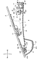
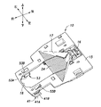
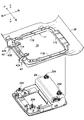
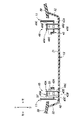
- FIG. 6 Perspective view of the device mounting structure according to the embodiment Cross-sectional view of device mounting structure (II-II cross-sectional view in FIG. 6) Perspective view of base member Perspective view of the first cover Exploded perspective view of bracket and roof console Plan view of the first cover Cross-sectional view of device mounting structure (VII-VII cross-sectional view in FIG. 6)
- the device mounting structure is provided at the boundary between the window panel and the roof of the vehicle.
- the window panels include a front window panel defining the front portion of the passenger compartment, a rear window panel defining the rear portion of the passenger compartment, and a pair of side window panels defining left and right sides of the passenger compartment.
- the vertical direction is the first direction
- the width direction of the window panel is the second direction
- the direction perpendicular to the first direction and the second direction is the third direction
- the side of the window panel on which the roof is arranged in the third direction is the third direction.
- the first side and the opposite side are the second side.
- the device mounting structure 1 is provided at the boundary between the front window panel 2 and the roof 3 in this embodiment.
- the front window panel 2 is slanted rearward upward.
- the second direction corresponds to the left-right direction
- the third direction corresponds to the front-rear direction
- the first side corresponds to the front side
- the second side corresponds to the rear side.
- the roof 3 defines the upper part of the passenger compartment 4 and is arranged substantially horizontally.
- the roof 3 has a roof panel (not shown) made of metal and a roof lining 3B attached to the lower surface of the roof panel.
- the window panel is preferably made of glass or resin.
- the device mounting structure 1 is attached to the upper end portion of the vehicle interior side surface (rear surface) of the front window panel 2, and includes a base member 10 that supports the device 7, a bracket 11 attached to the roof 3, and the base member 10 and the bracket 11. and a first cover 12 attached and covering the device 7 .
- Devices 7 may be sensors including cameras, radars, lidars, and the like.
- the base member 10, the bracket 11, and the first cover 12 are preferably made of resin.
- the base member 10 has a front surface and a rear surface, and has a plate-shaped base body portion 15 .
- the front surface of the base body portion 15 is formed flat.
- the front surface of the base body portion 15 is coupled to the vehicle interior side surface of the front window panel 2 with double-sided tape or an adhesive.
- the base body portion 15 extends vertically along the inner side surface of the front window panel 2 .
- the upper edge of the base body portion 15 extends laterally and is arranged near the upper edge of the front window panel 2 .
- a through hole 16 penetrating through the base main body 15 from the front surface to the rear surface is formed in the center of the upper part of the base main body 15 in the left-right direction.
- a light guide groove 17 is formed in front of the through hole 16 on the front surface of the base body portion 15 .
- the light guide groove 17 extends forward from the through hole 16 and gradually increases in width in the left-right direction toward the front. The depth of the light guide groove 17 becomes shallower from the through hole 16 toward the front.
- a mirror mounting hole 18 penetrating through the base body 15 from the front to the rear is formed in the center of the lower part of the base body 15 in the left-right direction.
- the mirror mounting hole 18 is arranged in front of the light guide groove 17 .
- a mirror base 22 for supporting a rearview mirror 21 is arranged inside the mirror mounting hole 18 .
- the mirror base 22 is bonded to the interior side of the front window panel 2 with double-sided tape or adhesive.
- the mirror base 22 extends downward from the front window panel 2 and then bends to extend rearward.
- a rearview mirror 21 is provided at the rear end of the mirror base 22 .
- a portion of the base member 10 that forms the central portion of the light guide groove 17 in the left-right direction may be formed by a detachable additional component 24 .
- the additional component 24 may be detachably attached to the base member 10 by elastic claws or the like. With the base member 10 coupled to the front window panel 2 , the additional component 24 is detachable from the base member 10 . By removing the additional part 24 from the base member 10, it becomes possible to clean the inside of the light guide groove 17 and the inner surface of the front window panel 2.
- the additional part 24 may be coupled to the front end portion so as to be rotatable about an axis extending in the left-right direction, and may be detachably locked to the base member 10 at the rear end portion.
- a device locking portion 26 for detachably locking the device 7 is provided on the upper rear surface of the base member 10 .
- the device locking portion 26 is formed by a plurality of elastic claws and locking grooves 41B.
- the device locking portion 26 has a pair of left and right locking grooves 41B that lock the front end of the device 7 and elastic claws that lock the rear end of the device 7 .
- the device 7 is attached to the rear surface of the base member 10 by the device locking portion 26 .
- the lens of the camera is arranged at a position corresponding to the through hole 16 when the device 7 is attached to the rear surface of the base member 10 .
- the transmitter and receiver are preferably arranged at positions corresponding to the through holes 16 .
- the bracket 11 is preferably coupled to at least one of the roof panel and the roof lining 3B.
- the bracket 11 is provided on the roof lining 3B.
- the bracket 11 may be formed integrally with the roof lining 3B.
- the bracket 11 includes a front side portion 11A extending left and right, left and right side portions 11B extending rearward from both left and right ends of the front side portion 11A, and extending left and right and coupled to rear ends of the left and right side portions 11B. It has a rear side portion 11C and is formed in a rectangular frame shape.
- the bracket 11 is provided at the edge of a mounting hole 28 vertically penetrating the roof lining 3B.
- a roof console 29 is arranged inside the bracket 11 .
- the roof console 29 is preferably fastened to the roof panel with fastening members 29A such as fasteners.
- Roof console 29 may be an interior light, display, or the like.
- the first cover 12 includes a cover body portion 31 formed in a plate shape and a pair of left and right covers provided on the left and right side edges of the cover body portion 31, respectively. and a side wall portion 32 .
- the cover main body 31 extends forward and backward below the base member 10 .
- the left and right cover side wall portions 32 extend upward from the cover body portion 31 .
- the upper edge of each cover side wall portion 32 is inclined upward toward the rear and extends along the vehicle interior side surface of the front window panel 2 .
- the first cover 12 is locked to the base member 10 and the bracket 11 by the first to sixth engaging portions 41-46.
- the base member 10 has a first engaging portion 41.
- the bracket 11 has a second engaging portion 42 and a third engaging portion 43 .
- the first cover 12 is engaged with a fourth engaging portion 44 that engages with the first engaging portion 41 , a fifth engaging portion 45 that engages with the second engaging portion 42 , and a third engaging portion 43 . and a mating sixth engaging portion 46 .
- the fourth engaging portion 44 is restricted by the first engaging portion 41 from moving in the vertical direction (first direction) and from moving forward (first side) in the front-rear direction (third direction). , left-right direction (second direction) and front-rear direction (third direction) to the rear side (first side).
- the first engaging portion 41 is provided at the front end portion of the lower surface of the base member 10. As shown in FIGS.
- the first engaging portion 41 includes left and right first wall portions 41A projecting from the lower portion of the rear surface of the base member 10, and recessed forward from the rear edge of each first wall portion 41A and penetrating in the left-right direction. It has left and right locking grooves 41B.
- a pair of first wall portions 41A and locking grooves 41B are arranged on the lower surface of the base member 10 on the left and right sides of the mirror mounting hole 18 .
- a recess 51 recessed rearward is formed in the center of the front edge of the first cover 12 in the left-right direction.
- the recess 51 penetrates through the first cover 12 in the thickness direction (vertical direction).
- the concave portion 51 is arranged below the mirror mounting hole 18 .
- the fourth engaging portion 44 has left and right tongues 44A provided on the left and right outer sides of the recess 51 at the front edge of the first cover 12 .
- Each tongue 44A is formed in a plate shape and extends forward.
- a front end 44B of each tongue 44A is formed in a columnar shape extending left and right.
- the thickness of the front end 44B in the vertical direction is formed thicker than the thickness of other portions of the tongue 44A.
- Each tongue 44A of the fourth engaging portion 44 is received in the locking groove 41B of the corresponding first engaging portion 41.
- the left and right locking grooves 41B restrict the left and right tongues 44A from moving in the vertical direction and moving forward, while allowing them to move in the horizontal direction and backward.
- Each front biasing portion 53 has a second wall portion 53A projecting downward from the rear surface of the base member 10, and a first elastic piece 53B extending forward and left and right outward from the rear edge of the second wall portion 53A.
- Each first elastic piece 53B abuts on the left and right corresponding tongues 44A from the left and right inner sides, and urges the tongues 44A left and right outward.
- the third engaging portion 43 has a plate-shaped support portion 43A projecting forward from the right portion of the front side portion 11A of the bracket 11, and a support hole 43B penetrating the support portion 43A in the vertical direction (first direction). .
- the support hole 43B is formed in a rectangular shape extending in the left-right direction.
- the rear edge of the first cover 12 is arranged behind the upper edge of the base member 10 and behind the front side portion 11A of the bracket 11 . That is, the rear portion of the first cover 12 is arranged below the front side portion 11A of the bracket 11 .
- the sixth engaging portion 46 is provided on the rear right side of the upper surface of the first cover 12 facing the base member 10 side.
- the sixth engaging portion 46 has a protrusion 46A protruding upward from the upper surface of the cover main body 31, and an elastic claw 46B provided on the side of the protrusion 46A.
- the elastic claw 46B is attached to the projecting piece portion 46A.
- the projecting piece portion 46A has a pair of left and right side wall portions 46C and a connecting wall portion 46D that connects the pair of side wall portions 46C.
- Each side wall portion 46C has a surface facing the left-right direction and extending in the front-rear direction.
- the connection wall portion 46D has a surface facing the front-rear direction and extending in the left-right direction.
- the projecting piece portion 46A is formed in an H shape.
- the elastic claw 46B is put on the connecting wall portion 46D from above and locked to the connecting wall portion 46D.
- the elastic claw 46B preferably has a front side piece 46E extending frontward from the upper end of the connecting wall portion 46D and a rear side piece 46F extending rearward from the upper end of the connecting wall portion 46D.
- the front side piece 46E and the rear side piece 46F of the elastic claw 46B are engaged with the connecting wall portion 46D, and movement in the vertical direction is restricted.
- the front side piece 46E and the rear side piece 46F of the elastic claw 46B are elastically deformed so as to be movable in the front-rear direction with respect to the connecting wall portion 46D.
- the intermediate portion of the front piece 46E projects forward from the front edges of the left and right side walls 46C, and the rear piece 46F projects rearward from the rear edges of the left and right side walls 46C.
- the sixth engaging portion 46 is inserted into the third engaging portion 43 .
- the front edge and the rear edge of the pair of side wall portions 46C of the sixth engaging portion 46 are in contact with the edge portion of the support hole 43B of the third engaging portion 43.
- the movement of the sixth engaging portion 46 in the front-rear direction is restricted by the third engaging portion 43 .
- the elastic claws 46B on the front and rear sides of the sixth engaging portion 46 are engaged with the upper edges of the support holes 43B of the third engaging portion 43, so that the sixth engaging portion 46 is held by the third engaging portion 43.
- vertical movement is restricted.
- the lateral width of the third engaging portion 43 is formed larger than the lateral width of the sixth engaging portion 46 . Thereby, the sixth engaging portion 46 can move in the left-right direction with respect to the third engaging portion 43 .
- the movement of the fifth engaging portion 45 in the vertical direction (first direction) and the front-rear direction (third direction) is restricted by the second engaging portion 42, and the movement thereof in the horizontal direction (second engaging portion 42) is restricted. and the second engaging portion 42 in the left-right direction (second direction).
- the second engaging portion 42 is provided on the left side of the front side portion 11A of the bracket 11 .
- the second engaging portion 42 has a plate-shaped support portion 42A projecting forward from the front side portion 11A, and a support hole 42B penetrating the support portion 42A in the vertical direction (first direction).
- the second engaging portion 42 is formed in a rectangular shape extending in the left-right direction.
- the second engaging portion 42 and the third engaging portion 43 are preferably arranged apart from each other in the left and right direction on the front side portion 11 ⁇ /b>A of the bracket 11 .
- the fifth engaging portion 45 is provided on the rear left side of the upper surface of the first cover 12 .
- the fifth engaging portion 45 has a projecting piece 45A projecting upward from the upper surface of the cover body portion 31, and an elastic claw 45B provided on the side of the projecting piece 45A.
- the elastic claw 45B is attached to the projecting piece portion 45A.
- the projecting piece portion 45A has a pair of left and right side wall portions 45C and a connecting wall portion 45D that connects the pair of side wall portions 45C.
- Each side wall portion 45C has a surface facing the left-right direction and extending in the front-rear direction.
- the connection wall portion 45D has a surface facing the front-rear direction and extending in the left-right direction.
- the elastic claw 45B covers the connecting wall portion 45D from above and is engaged with the connecting wall portion 45D.
- the elastic claw 45B preferably has a front side piece 45E extending from the upper end of the connecting wall portion 45D to the front side, and a rear side piece 45F extending from the upper end of the connecting wall portion 45D to the rear side.
- the front side piece 45E and the rear side piece 45F of the elastic claw 45B are engaged with the connecting wall portion 45D, and movement in the vertical direction is restricted.
- the front side piece 45E and the rear side piece 45F of the elastic claw 45B are elastically deformed so as to be movable in the front-rear direction with respect to the connecting wall portion 45D.
- An intermediate portion of the front piece 45E protrudes forward from the front edges of the pair of left and right side walls 45C.
- An intermediate portion of the rear piece 45F protrudes rearward beyond the rear edges of the pair of left and right side walls 45C.
- a biasing member 55 is coupled to one end of the fifth engaging portion 45 in the left-right direction (second direction).
- a rib 57 as a contact portion that contacts the second engaging portion 42 is provided at the other end of the fifth engaging portion 45 in the left-right direction (second direction).
- the biasing member 55 is coupled to the right side wall portion 45 ⁇ /b>C of the fifth engaging portion 45 .
- the biasing member 55 is preferably an elastic piece extending downward and rightward from the upper end of the right side wall portion 45C. The biasing member 55 can be elastically deformed in the left-right direction.
- the rib 57 protrudes leftward from the left side wall portion 45C of the fifth engaging portion 45 .
- the rib 57 extends vertically along the left side surface of the left side wall portion 45C.
- the fifth engaging portion 45 is inserted into the second engaging portion 42 .
- the front edge and the rear edge of the pair of side wall portions 45C of the fifth engaging portion 45 are in contact with the edge portion of the support hole 42B forming the second engaging portion 42.
- the movement of the fifth engaging portion 45 in the front-rear direction is restricted by the second engaging portion 42 .
- the front and rear elastic claws 45B of the fifth engaging portion 45 are engaged with the upper edges of the support holes 42B forming the fifth engaging portion 45, so that the fifth engaging portion 45 is connected to the second engaging portion. 42 restricts movement in the vertical direction.
- the lateral width of the second engaging portion 42 is formed to be larger than the lateral width of the fifth engaging portion 45 including the pair of side wall portions 45C, the connecting wall, and the contact portion.
- a second cover 61 is attached to the front portion of the first cover 12 .
- the second cover 61 has a left piece 61A and a right piece 61B that are joined together. Each of the left piece 61A and the right piece 61B is coupled to the front end of the bottom surface of the first cover 12 .
- the second cover 61 protrudes downward from the front end of the first cover 12 .
- the second cover 61 covers the recess 51 of the first cover 12 and the front end of the base member 10 .
- a rear portion of the second cover 61 is formed with a through hole 61C through which the mirror base 22 passes.
- a ventilation hole 61D is formed in the front portion of the second cover 61 for taking in the air in the vehicle interior into the second cover.
- first cover 12 is generally centered in the left-right direction with respect to the base member 10 .
- the first cover 12 With the tongues 44A inserted into the locking grooves 41B, the first cover 12 can rotate within a predetermined range around the front ends 44B of the tongues 44A. The rear end can move up and down. Next, the operator moves the rear end of the first cover 12 upward, inserts the protrusion 45A of the fifth engaging portion 45 into the support hole 42B of the second engaging portion 42, and moves the sixth engaging portion 45A. The protrusion 46A of the joining portion 46 is inserted into the support hole 43B of the third engaging portion 43. As shown in FIG. As a result, the elastic claw 45B of the fifth engaging portion 45 is engaged with the edge of the support hole 42B of the second engaging portion 42, and the elastic claw 46B of the sixth engaging portion 46 is engaged with the third engaging portion.
- the first cover 12 is attached to the base member 10 and the bracket 11 . After that, the left piece 61 A and the right piece 61 B of the second cover 61 are attached to the first cover 12 .
- the device mounting structure 1 that can be easily mounted on the base member 10 and the roof 3 .
- the displacement is allowed by moving the fourth engaging portion 44 in the horizontal direction with respect to the first engaging portion 41 .
- the displacement is allowed by moving the fourth engaging portion 44 in the front-rear direction with respect to the first engaging portion 41 .
- the second engaging portion 42 and the fifth engaging portion 45 and engaging the third engaging portion 43 and the sixth engaging portion 46 in the vertical direction and the front-rear direction.
- the position of the first cover 12 with respect to the bracket 11 is determined. Further, the position of the first cover 12 relative to the bracket 11 in the left-right direction is determined by the contact between the second engaging portion 42 and the fifth engaging portion 45 in the left-right direction.
- the urging member 55 of the fifth engaging portion 45 abuts against the hole wall at the right end of the support hole 42B of the second engaging portion 42, the projecting piece portion 45A of the fifth engaging portion 45 is moved against the support hole 42B. , and the rib 57 comes into contact with the hole wall at the left end of the support hole 42B. Thereby, the position of the first cover 12 in the left-right direction is determined with respect to the bracket 11 . Since the biasing member 55 extends in the vertical direction, which is the axial direction of the support hole 42B, it can reliably come into contact with the hole wall of the support hole 42B. Similarly, since the rib 57 extends in the vertical direction, which is the axial direction of the support hole 42B, it can reliably contact the hole wall of the support hole 42B.
- the protruding piece portion 46A of the sixth engaging portion 46 engages in the third engaging portion in the left-right direction. It is arranged with a gap from the support hole 42B of the portion 43 .
- the ribs 57 of the fifth engaging portion 45 can reliably contact the support holes 42B of the second engaging portion 42, and the position of the first cover 12 relative to the bracket 11 in the left-right direction is determined.
- the device mounting structure 1 may be provided at the boundary between other window panels including a rear window panel and side window panels and the roof 3 .
- the configurations of the second engaging portion 42 and the fifth engaging portion 45 may be replaced with each other, and the configurations of the third engaging portion 43 and the sixth engaging portion 46 may be replaced with each other.
Landscapes
- Engineering & Computer Science (AREA)
- Mechanical Engineering (AREA)
- Connection Of Plates (AREA)
- Fittings On The Vehicle Exterior For Carrying Loads, And Devices For Holding Or Mounting Articles (AREA)
- Vehicle Interior And Exterior Ornaments, Soundproofing, And Insulation (AREA)
Abstract
Description
2 :フロントウインドウパネル
3 :ルーフ
4 :車室
7 :デバイス
10 :ベース部材
11 :ブラケット
12 :第1カバー
15 :ベース本体部
41 :第1係合部
42 :第2係合部
42A :支持部
42B :支持孔
43 :第3係合部
43A :支持部
43B :支持孔
44 :第4係合部
45 :第5係合部
45A :突片部
45B :弾性爪
46 :第6係合部
46A :突片部
46B :弾性爪
53 :前側付勢部
55 :付勢部材
57 :リブ
61 :第2カバー
Claims (6)
- 車両のウインドウパネルとルーフとの境界部に設けられるデバイス取付構造であって、
上下方向を第1方向、前記ウインドウパネルの幅方向を第2方向、前記第1方向及び前記第2方向に直交する方向を第3方向、前記第3方向において前記ルーフに対して前記ウインドウパネルが配置された側を第1側、相反する側を第2側とし、
前記ウインドウパネルの車内側面に取り付けられ、デバイスを支持するベース部材と、
前記ルーフに取り付けられたブラケットと、
前記ベース部材及び前記ブラケットに取り付けられ、前記デバイスを覆う第1カバーとを有し、
前記ベース部材は、第1係合部を有し、
前記ブラケットは、第2係合部と、第3係合部とを有し、
前記第1カバーは、前記第1係合部に係合する第4係合部と、前記第2係合部に係合する第5係合部と、前記第3係合部に係合する第6係合部とを有し、
前記第4係合部は、前記第1係合部によって、前記第1方向及び前記第3方向における前記第1側への移動が規制される一方、前記第2方向及び前記第3方向における第2側への移動が許容され、
前記第6係合部は、前記第3係合部によって、前記第1方向及び前記第3方向への移動が規制される一方、前記第2方向への移動が許容され、
前記第5係合部は、前記第2係合部によって、前記第1方向及び前記第3方向への移動が規制されると共に、前記第2係合部との間に設けられた付勢部材によって前記第2方向において前記第2係合部と突き当てられているデバイス取付構造。 - 前記第2係合部は、前記第1方向に貫通した貫通孔を有し、
前記第5係合部は、前記第1方向に延び、前記孔に挿入される突片を有し、
前記第2係合部の前記第2方向における長さは、前記第5係合部の前記第2方向における長さよりも大きく、
前記第5係合部の前記第2方向における一端には前記付勢部材が結合され、
前記第5係合部の前記第2方向における他端には、前記第2係合部に当接する当接部が設けられている請求項1に記載のデバイス取付構造。 - 前記当接部は、前記第1方向に延びるリブである請求項2に記載のデバイス取付構造。
- 前記当接部は、前記第2係合部の前記孔の孔壁に当接している請求項3に記載のデバイス取付構造。
- 前記付勢部材は、前記第2係合部の前記孔の孔壁に当接している請求項2~4のいずれか1つの項に記載のデバイス取付構造。
- 前記第5係合部が前記第2係合部と前記第2方向において当接しているときに、前記第6係合部は前記第2方向において前記第3係合部と隙間を介して配置される請求項1~3のいずれか1つの項に記載のデバイス取付構造。
Priority Applications (3)
| Application Number | Priority Date | Filing Date | Title |
|---|---|---|---|
| US18/288,299 US12269395B2 (en) | 2021-05-31 | 2022-04-28 | Device attachment structure |
| MX2023012803A MX2023012803A (es) | 2021-05-31 | 2022-04-28 | Estructura de fijacion de dispositivo. |
| CN202280030346.9A CN117320923A (zh) | 2021-05-31 | 2022-04-28 | 设备安装构造 |
Applications Claiming Priority (2)
| Application Number | Priority Date | Filing Date | Title |
|---|---|---|---|
| JP2021091793A JP7473504B2 (ja) | 2021-05-31 | 2021-05-31 | デバイス取付構造 |
| JP2021-091793 | 2021-05-31 |
Publications (1)
| Publication Number | Publication Date |
|---|---|
| WO2022255019A1 true WO2022255019A1 (ja) | 2022-12-08 |
Family
ID=84324249
Family Applications (1)
| Application Number | Title | Priority Date | Filing Date |
|---|---|---|---|
| PCT/JP2022/019279 Ceased WO2022255019A1 (ja) | 2021-05-31 | 2022-04-28 | デバイス取付構造 |
Country Status (5)
| Country | Link |
|---|---|
| US (1) | US12269395B2 (ja) |
| JP (1) | JP7473504B2 (ja) |
| CN (1) | CN117320923A (ja) |
| MX (1) | MX2023012803A (ja) |
| WO (1) | WO2022255019A1 (ja) |
Families Citing this family (1)
| Publication number | Priority date | Publication date | Assignee | Title |
|---|---|---|---|---|
| JP7473504B2 (ja) * | 2021-05-31 | 2024-04-23 | 株式会社ニフコ | デバイス取付構造 |
Citations (5)
| Publication number | Priority date | Publication date | Assignee | Title |
|---|---|---|---|---|
| JP2018012406A (ja) * | 2016-07-20 | 2018-01-25 | 株式会社ニフコ | カメラユニット |
| JP2018016296A (ja) * | 2016-07-15 | 2018-02-01 | 株式会社石▲崎▼本店 | 車両用補機の取付構造 |
| JP2020097332A (ja) * | 2018-12-18 | 2020-06-25 | 本田技研工業株式会社 | 輸送機器およびセンサブラケット |
| JP2020121580A (ja) * | 2019-01-29 | 2020-08-13 | 株式会社ニフコ | 車載カメラ用ブラケット |
| JP2021049916A (ja) * | 2019-09-26 | 2021-04-01 | いすゞ自動車株式会社 | カメラカバー取付構造 |
Family Cites Families (17)
| Publication number | Priority date | Publication date | Assignee | Title |
|---|---|---|---|---|
| DE102011108392A1 (de) * | 2010-09-25 | 2012-03-29 | Volkswagen Ag | Fahrzeug mit einer Dachkonsole |
| JP6052246B2 (ja) * | 2014-07-10 | 2016-12-27 | トヨタ自動車株式会社 | 車載カメラの取り付け構造 |
| DE102014012001B4 (de) * | 2014-08-12 | 2021-07-22 | Daimler Ag | Trägervorrichtung zum Befestigen an einer Scheibe eines Kraftwagens und Kraftwagen |
| GB2554302B (en) | 2015-05-22 | 2021-01-13 | Nifco Inc | Cover for onboard electronic device |
| US11150448B2 (en) * | 2016-11-06 | 2021-10-19 | Denso Corporation | Vehicle windshield mounted camera module |
| JP7163608B2 (ja) * | 2018-04-13 | 2022-11-01 | 株式会社デンソー | 車両用部品の取付け構造、車両用部品の取付け方法および車両用のウインドシールド |
| CN110579743A (zh) * | 2018-06-08 | 2019-12-17 | 日本电产株式会社 | 支架以及传感器装置 |
| JP7099103B2 (ja) * | 2018-07-12 | 2022-07-12 | 株式会社デンソー | カメラモジュール |
| JP7042206B2 (ja) * | 2018-12-18 | 2022-03-25 | 本田技研工業株式会社 | 輸送機器およびセンサブラケット |
| JP7147613B2 (ja) * | 2019-02-14 | 2022-10-05 | トヨタ自動車株式会社 | カメラ搭載構造 |
| JP7192565B2 (ja) * | 2019-02-22 | 2022-12-20 | トヨタ自動車株式会社 | カメラ搭載構造 |
| US11338742B2 (en) * | 2019-07-25 | 2022-05-24 | Nifco Inc. | Bracket for in-vehicle device and holding device for in-vehicle device |
| US11097691B2 (en) * | 2019-09-26 | 2021-08-24 | Honda Motor Co., Ltd. | Window heating system for vehicular camera |
| US10981520B1 (en) * | 2019-11-14 | 2021-04-20 | Zf Friedrichshafen Ag | Driver assist system for a vehicle |
| JP7437268B2 (ja) * | 2020-08-27 | 2024-02-22 | 本田技研工業株式会社 | 移動体 |
| US11851008B2 (en) * | 2021-03-15 | 2023-12-26 | Illinois Tool Works Inc. | Camera bracket assembly |
| JP7473504B2 (ja) * | 2021-05-31 | 2024-04-23 | 株式会社ニフコ | デバイス取付構造 |
-
2021
- 2021-05-31 JP JP2021091793A patent/JP7473504B2/ja active Active
-
2022
- 2022-04-28 CN CN202280030346.9A patent/CN117320923A/zh active Pending
- 2022-04-28 MX MX2023012803A patent/MX2023012803A/es unknown
- 2022-04-28 US US18/288,299 patent/US12269395B2/en active Active
- 2022-04-28 WO PCT/JP2022/019279 patent/WO2022255019A1/ja not_active Ceased
Patent Citations (5)
| Publication number | Priority date | Publication date | Assignee | Title |
|---|---|---|---|---|
| JP2018016296A (ja) * | 2016-07-15 | 2018-02-01 | 株式会社石▲崎▼本店 | 車両用補機の取付構造 |
| JP2018012406A (ja) * | 2016-07-20 | 2018-01-25 | 株式会社ニフコ | カメラユニット |
| JP2020097332A (ja) * | 2018-12-18 | 2020-06-25 | 本田技研工業株式会社 | 輸送機器およびセンサブラケット |
| JP2020121580A (ja) * | 2019-01-29 | 2020-08-13 | 株式会社ニフコ | 車載カメラ用ブラケット |
| JP2021049916A (ja) * | 2019-09-26 | 2021-04-01 | いすゞ自動車株式会社 | カメラカバー取付構造 |
Also Published As
| Publication number | Publication date |
|---|---|
| MX2023012803A (es) | 2023-11-08 |
| US12269395B2 (en) | 2025-04-08 |
| CN117320923A (zh) | 2023-12-29 |
| US20240217449A1 (en) | 2024-07-04 |
| JP2022184126A (ja) | 2022-12-13 |
| JP7473504B2 (ja) | 2024-04-23 |
Similar Documents
| Publication | Publication Date | Title |
|---|---|---|
| CN109328153B (zh) | 摄像头单元 | |
| JP6592205B2 (ja) | 車載電子機器取付構造 | |
| JP5428784B2 (ja) | 車両内装品の組付構造 | |
| CN109878428B (zh) | 传感器搭载结构 | |
| JP2012091597A (ja) | 車載カメラの取付構造 | |
| JPWO2016190153A1 (ja) | 車載用電子機器のカバー | |
| JP6445431B2 (ja) | 車両用ドアライニング及びその取付構造 | |
| CN112172686A (zh) | 传感器装配构造 | |
| JP2019099047A (ja) | センサー搭載構造 | |
| WO2022255019A1 (ja) | デバイス取付構造 | |
| CN112277821A (zh) | 车载设备用支架以及车载设备的保持装置 | |
| JP2019099048A (ja) | センサー搭載構造 | |
| JP4766431B2 (ja) | 自動車のインストルメントパネル機器取付構造 | |
| JP2022105592A (ja) | 車載カメラ | |
| US11970119B2 (en) | Attachment device | |
| JP7199463B2 (ja) | 車両用外界検知センサの取付部構造 | |
| JP2018188048A (ja) | 車両用サイドミラー | |
| JP5123898B2 (ja) | 装飾部材の取付構造 | |
| JP7626010B2 (ja) | 車載装置 | |
| JP2021084567A (ja) | 部材の取付構造 | |
| JP2017114465A (ja) | 車載用電装品の取付け具 | |
| JP2025159858A (ja) | カバー部材の取付構造 | |
| CN114514146A (zh) | 车辆的装饰板 | |
| JP2009218180A (ja) | ベゼル取付構造 | |
| CN112208308A (zh) | 车辆用车窗板构造 |
Legal Events
| Date | Code | Title | Description |
|---|---|---|---|
| 121 | Ep: the epo has been informed by wipo that ep was designated in this application |
Ref document number: 22815774 Country of ref document: EP Kind code of ref document: A1 |
|
| WWE | Wipo information: entry into national phase |
Ref document number: 202280030346.9 Country of ref document: CN |
|
| WWE | Wipo information: entry into national phase |
Ref document number: 18288299 Country of ref document: US |
|
| WWE | Wipo information: entry into national phase |
Ref document number: MX/A/2023/012803 Country of ref document: MX |
|
| WWE | Wipo information: entry into national phase |
Ref document number: 2301007679 Country of ref document: TH |
|
| NENP | Non-entry into the national phase |
Ref country code: DE |
|
| 122 | Ep: pct application non-entry in european phase |
Ref document number: 22815774 Country of ref document: EP Kind code of ref document: A1 |
|
| WWG | Wipo information: grant in national office |
Ref document number: 18288299 Country of ref document: US |