WO2022249862A1 - カフカバー - Google Patents
カフカバー Download PDFInfo
- Publication number
- WO2022249862A1 WO2022249862A1 PCT/JP2022/019550 JP2022019550W WO2022249862A1 WO 2022249862 A1 WO2022249862 A1 WO 2022249862A1 JP 2022019550 W JP2022019550 W JP 2022019550W WO 2022249862 A1 WO2022249862 A1 WO 2022249862A1
- Authority
- WO
- WIPO (PCT)
- Prior art keywords
- cuff
- covering portion
- cover
- cuff structure
- covering
- Prior art date
- Legal status (The legal status is an assumption and is not a legal conclusion. Google has not performed a legal analysis and makes no representation as to the accuracy of the status listed.)
- Ceased
Links
Images


Classifications
-
- A—HUMAN NECESSITIES
- A61—MEDICAL OR VETERINARY SCIENCE; HYGIENE
- A61B—DIAGNOSIS; SURGERY; IDENTIFICATION
- A61B5/00—Measuring for diagnostic purposes; Identification of persons
- A61B5/02—Detecting, measuring or recording for evaluating the cardiovascular system, e.g. pulse, heart rate, blood pressure or blood flow
- A61B5/021—Measuring pressure in heart or blood vessels
- A61B5/022—Measuring pressure in heart or blood vessels by applying pressure to close blood vessels, e.g. against the skin; Ophthalmodynamometers
- A61B5/02233—Occluders specially adapted therefor
-
- A—HUMAN NECESSITIES
- A61—MEDICAL OR VETERINARY SCIENCE; HYGIENE
- A61B—DIAGNOSIS; SURGERY; IDENTIFICATION
- A61B5/00—Measuring for diagnostic purposes; Identification of persons
- A61B5/02—Detecting, measuring or recording for evaluating the cardiovascular system, e.g. pulse, heart rate, blood pressure or blood flow
- A61B5/021—Measuring pressure in heart or blood vessels
- A61B5/022—Measuring pressure in heart or blood vessels by applying pressure to close blood vessels, e.g. against the skin; Ophthalmodynamometers
- A61B5/02225—Measuring pressure in heart or blood vessels by applying pressure to close blood vessels, e.g. against the skin; Ophthalmodynamometers using the oscillometric method
-
- A—HUMAN NECESSITIES
- A61—MEDICAL OR VETERINARY SCIENCE; HYGIENE
- A61B—DIAGNOSIS; SURGERY; IDENTIFICATION
- A61B5/00—Measuring for diagnostic purposes; Identification of persons
- A61B5/02—Detecting, measuring or recording for evaluating the cardiovascular system, e.g. pulse, heart rate, blood pressure or blood flow
- A61B5/021—Measuring pressure in heart or blood vessels
- A61B5/022—Measuring pressure in heart or blood vessels by applying pressure to close blood vessels, e.g. against the skin; Ophthalmodynamometers
- A61B5/0225—Measuring pressure in heart or blood vessels by applying pressure to close blood vessels, e.g. against the skin; Ophthalmodynamometers the pressure being controlled by electric signals, e.g. derived from Korotkoff sounds
-
- A—HUMAN NECESSITIES
- A61—MEDICAL OR VETERINARY SCIENCE; HYGIENE
- A61B—DIAGNOSIS; SURGERY; IDENTIFICATION
- A61B5/00—Measuring for diagnostic purposes; Identification of persons
- A61B5/02—Detecting, measuring or recording for evaluating the cardiovascular system, e.g. pulse, heart rate, blood pressure or blood flow
- A61B5/024—Measuring pulse rate or heart rate
- A61B5/0245—Measuring pulse rate or heart rate by using sensing means generating electric signals, i.e. ECG signals
-
- A—HUMAN NECESSITIES
- A61—MEDICAL OR VETERINARY SCIENCE; HYGIENE
- A61B—DIAGNOSIS; SURGERY; IDENTIFICATION
- A61B5/00—Measuring for diagnostic purposes; Identification of persons
- A61B5/24—Detecting, measuring or recording bioelectric or biomagnetic signals of the body or parts thereof
- A61B5/25—Bioelectric electrodes therefor
- A61B5/251—Means for maintaining electrode contact with the body
- A61B5/256—Wearable electrodes, e.g. having straps or bands
-
- A—HUMAN NECESSITIES
- A61—MEDICAL OR VETERINARY SCIENCE; HYGIENE
- A61B—DIAGNOSIS; SURGERY; IDENTIFICATION
- A61B5/00—Measuring for diagnostic purposes; Identification of persons
- A61B5/24—Detecting, measuring or recording bioelectric or biomagnetic signals of the body or parts thereof
- A61B5/25—Bioelectric electrodes therefor
- A61B5/279—Bioelectric electrodes therefor specially adapted for particular uses
- A61B5/28—Bioelectric electrodes therefor specially adapted for particular uses for electrocardiography [ECG]
- A61B5/282—Holders for multiple electrodes
-
- A—HUMAN NECESSITIES
- A61—MEDICAL OR VETERINARY SCIENCE; HYGIENE
- A61B—DIAGNOSIS; SURGERY; IDENTIFICATION
- A61B5/00—Measuring for diagnostic purposes; Identification of persons
- A61B5/68—Arrangements of detecting, measuring or recording means, e.g. sensors, in relation to patient
- A61B5/6801—Arrangements of detecting, measuring or recording means, e.g. sensors, in relation to patient specially adapted to be attached to or worn on the body surface
- A61B5/6802—Sensor mounted on worn items
- A61B5/681—Wristwatch-type devices
-
- A—HUMAN NECESSITIES
- A61—MEDICAL OR VETERINARY SCIENCE; HYGIENE
- A61B—DIAGNOSIS; SURGERY; IDENTIFICATION
- A61B5/00—Measuring for diagnostic purposes; Identification of persons
- A61B5/68—Arrangements of detecting, measuring or recording means, e.g. sensors, in relation to patient
- A61B5/6801—Arrangements of detecting, measuring or recording means, e.g. sensors, in relation to patient specially adapted to be attached to or worn on the body surface
- A61B5/6813—Specially adapted to be attached to a specific body part
- A61B5/6824—Arm or wrist
-
- A—HUMAN NECESSITIES
- A61—MEDICAL OR VETERINARY SCIENCE; HYGIENE
- A61B—DIAGNOSIS; SURGERY; IDENTIFICATION
- A61B5/00—Measuring for diagnostic purposes; Identification of persons
- A61B5/68—Arrangements of detecting, measuring or recording means, e.g. sensors, in relation to patient
- A61B5/6801—Arrangements of detecting, measuring or recording means, e.g. sensors, in relation to patient specially adapted to be attached to or worn on the body surface
- A61B5/683—Means for maintaining contact with the body
- A61B5/6831—Straps, bands or harnesses
Definitions
- the present invention belongs to the healthcare-related technical field, and particularly relates to a cuff cover used for a biological information measurement device.
- biometric information information related to their physical health
- portable measuring devices including portable devices that can measure both blood pressure values and electrocardiographic waveforms (for example, Patent Document 1, etc.).
- the present invention aims to provide a cuff cover that is suitable for a biological information measurement device that includes a cuff for blood pressure measurement and an electrode for electrocardiogram measurement.
- the cuff cover includes: A biological information measuring device comprising a cuff structure having one or more cuffs and one or more electrodes and mounting means for measuring the blood pressure level and electrocardiographic waveform of the human body while being mounted on the human body by the mounting means , a cuff cover covering the cuff structure, a covering portion formed of a non-conductive material and covering the cuff structure; attachment means for attaching the covering to the cuff structure; an energization assisting means provided in the covering portion for assisting energization between the electrodes included in the cuff structure covered by the covering portion and the human body when the biological information measuring device is worn on the human body; characterized by having
- the cuff cover having such a configuration, it is possible to prevent the electrode from being insulated from the human body to be measured by the cover, preventing the electrocardiographic measurement from becoming impossible.
- the attachment means includes various means according to the form of the cuff cover, and for example, adhesive, double-sided tape, rubber band, hook-and-loop fastener, snap button, etc. can be employed.
- the energization auxiliary means may be an opening provided in the cover so that the electrode can be exposed.
- the covering portion may be formed in a bag-like shape capable of accommodating the cuff structure, and may include an accommodation opening that is an opening for accommodating the cuff structure in the covering portion.
- the cuff structure can be housed in the bag-like covering portion and the entirety can be covered, so that the function of protecting the cuff structure can be further improved.
- the covering portion is formed of a material having stretchability, and includes an inner covering portion, which is a side that contacts the human body in a state in which the cuff structure is accommodated, and is provided with the electric conduction auxiliary means, and the cuff structure. an outer covering portion facing the inner covering portion through the cuff structure in a state where the structure is housed;
- the accommodation opening is provided in the outer covering portion and is an opening having an area smaller than the area of the cuff structure when the cuff structure is viewed from above.
- the stretchability of the material allows the cuff structure to be expanded larger than the area, and
- the attachment means may be the accommodation opening in the covering portion.
- the expandable accommodation opening provided in the covering portion can be used as the mounting means for the cuff cover without separately providing a means for mounting the cuff cover, thereby reducing the number of parts of the product. can do.
- the covering portion includes a plurality of the accommodating openings, and a plurality of structures including the cuff structure can be accommodated in the covering portion from the different accommodating openings.
- a fixing portion for fixing the inner covering portion and the outer covering portion may be provided at a location positioned between the accommodation opening.
- a cuff cover that is suitable for a biological information measurement device that includes a cuff for blood pressure measurement and an electrode for electrocardiogram measurement.
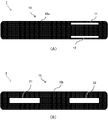
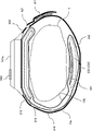
- FIG. 1A is a schematic plan view showing the appearance of a cuff cover according to Example 1.
- FIG. 1B is a schematic bottom view showing the appearance of the cuff cover according to the first embodiment;
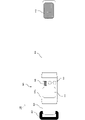
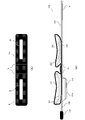
- FIG. 2 is a schematic plan view showing the appearance of the biological information measuring device using the cuff cover according to the first embodiment.
- 3A is a schematic bottom view showing the appearance of a biological information measuring device using the cuff cover according to the first embodiment;
- FIG. 3B is a schematic side view showing the appearance of the biological information measuring device using the cuff cover according to the first embodiment;
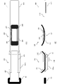
- FIG. FIG. 4A is a first diagram illustrating a state where the cuff cover according to the first embodiment is attached to the biological information measuring device;
- FIG. 7B is a second diagram illustrating a conductive auxiliary portion of the cuff cover according to Modification 1 of Embodiment 1;
- 8A is a first diagram illustrating a conductive auxiliary portion of a cuff cover according to Modification 2 of Embodiment 1.
- FIG. 8B is a second diagram illustrating a conductive assisting portion of the cuff cover according to Modification 2 of Embodiment 1;
- 9A is a schematic plan view showing the appearance of a cuff cover according to Modification 3 of Embodiment 1.
- FIG. 9B is an explanatory diagram illustrating a state in which the cuff cover according to Modification 3 of Embodiment 1 is attached to the biological information measuring device;
- FIG. 9B is an explanatory diagram illustrating a state in which the cuff cover according to Modification 3 of Embodiment 1 is attached to the biological information measuring device;
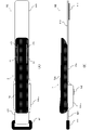
- FIG. 10A is a schematic plan view showing the appearance of a cuff cover according to Example 2.
- FIG. 10B is a schematic bottom view showing the appearance of the cuff cover according to Example 2.
- FIG. 11A is a schematic bottom view showing the appearance of a biological information measuring device using the cuff cover according to the second embodiment.
- 11B is a schematic side view showing the appearance of a biological information measuring device using the cuff cover according to the second embodiment;
- FIG. 1 is a diagram showing the appearance of a cuff cover 1 according to this embodiment
- FIGS. 2 and 3 are schematic diagrams showing the appearance configuration of a biological information measurement device 100 using the cuff cover 1.
- FIG. 4 and 5 are diagrams for explaining the state in which the cuff cover 1 is attached to the biological information measuring device 100
- FIG. 6 is the state in which the biological information measuring device 100 with the cuff cover 1 attached is worn on the wrist.
- FIG. 4 is an explanatory diagram showing the arrangement relationship of each component at the time.
- FIG. 1A is a schematic plan view showing the appearance of the cuff cover 1
- FIG. 1B is a schematic bottom view showing the appearance of the cuff cover 1.
- FIG. 1 the cuff cover 1 according to this embodiment has a substantially rectangular shape having a longitudinal direction, and as will be described later, the cuff structure of the biological information measuring device 100 (in this embodiment, the cuff structure will be described later).
- the covering portion 10 is formed in the shape of a bag capable of accommodating the pressing cuff portion 210 and the sensing cuff portion 220) therein.
- the covering portion 10 is formed of a stretchable cloth material, but the method is not particularly limited, and it may be formed by knitting, or by joining a plurality of cloth materials by sewing or heat welding. good too.
- the inner covering portion 10a is provided with electrode openings 11 and 12 for exposing the electrodes of the cuff structure accommodated in the covering portion as described later. That is, in this embodiment, the electrode openings 11 and 12 correspond to the energization auxiliary means. Further, the outer covering portion 10b is provided with receiving openings 21 and 22 for accommodating the cuff structure inside the covering portion 10b.
- FIG. 2 is a schematic plan view showing the appearance of the biological information measuring device 100 to which the cuff cover 1 is attached.
- 3A is a schematic diagram showing the bottom surface of the biological information measuring device 100
- FIG. 3B is a schematic diagram showing the side surface of the biological information measuring device 100. As shown in FIG.
- the biological information measurement device 100 generally includes a body portion 101, a pressure cuff portion 210 and a sensing cuff portion 220 (cuff structure), and a belt portion 400. Blood pressure values and electrocardiographic waveforms can be measured while the device is worn on the wrist.
- the belt portion 400 has a first belt portion 410 having a hook-and-loop fastener 411 and a second belt portion 420 having a belt loop 421 .
- the first belt portion 410 is wrapped around the wrist and then passed through the belt loop 421, and the hook-and-loop fastener 411 is attached to the second belt portion formed with a loop for engaging the hook. Fixing is performed by sticking to an arbitrary position of 420 .
- the body portion 101 includes a housing 101 a, a display portion 111 , an operation portion 112 and a first electrode 140 .
- the main unit 101 includes a power supply unit, a control unit, a circuit electrically connected to electrodes described later, a pump for pumping air to the cuff, a fluid flow path, an exhaust valve, and the like.
- the power source may be a battery that supplies power necessary for operating the device, and may be a secondary battery such as a lithium ion battery, or a primary battery.
- the display unit 111 includes a display device such as a liquid crystal display, and may include an LED indicator or the like.
- the operation unit 112 includes, for example, various operation buttons such as a power button.
- the display unit 111 such as a touch panel display and the operation unit 112 may be integrated.
- the pressure cuff part 210 which is one of the cuff structures, is fixed to the housing 101a of the main body by the fixing part K1, and is inflated by the air sent from the pump to press the wrist of the attachment part. It is configured including a pressure cuff 211 that presses and a pressure cuff plate 212 that supports the pressure cuff 211 .
- the operation unit 112 is operated to start measurement. Specifically, when air is injected into the pressure cuff 211, the wrist is pressed against the sensing cuff 221 side, and the wrist (artery thereof) is compressed, and the artery is occluded. After the blood flow is temporarily stopped in this way, air is gradually discharged from the pressure cuff 211 to return the arterial blood flow, and the pressure at that time is measured by the sensing cuff 221 . That is, blood pressure measurement is performed by a so-called oscillometric method.
- the second electrode 223 and the third electrode 224 are in contact with (pressed against) the surface of the wrist. Therefore, by touching the first electrode 140 provided on the housing 101a of the main body 101 with the finger of the other hand not wearing the biological information measuring device 100, the potential difference between the first electrode 140 and the second electrode 223 is reduced. Based on this, an electrocardiographic waveform can be measured by the so-called I-lead method.
- the attachment of the cuff cover 1 to the biological information measuring device 100 is performed by accommodating the pressing cuff part 210 from the accommodation opening 21 and the sensing cuff part 220 from the accommodation opening 22 into the covering part 10, respectively.
- the area of the accommodation opening 21 when the outer covering portion 10b is viewed in plan is smaller than the area of the pressing cuff portion 210 in plan view.
- the accommodation openings 21 and 22 are spread apart with fingers (or the fabric around the accommodation openings is spread). pulling) to expand each of the accommodation openings 21 and 22 and then accommodate the pressing cuff portion 210 and the sensing cuff portion 220 .
- FIG. 7 is a diagram showing a cuff cover 4 that is a first modification of the cuff cover 1 according to the first embodiment.
- FIG. 7A is a partial plan view of the inner covering portion 10a of the cuff cover 4 according to this modification
- FIG. 7B is an explanatory diagram illustrating conductive fiber portions 41 and 42 of the cuff cover 4 according to this modification.
- the cuff cover 4 according to this modified example has the same basic configuration as the cuff cover 1, such components are denoted by the same reference numerals as those of the cuff cover 1, and overlapping descriptions are omitted.
- the cuff cover 4 according to this modification includes conductive fiber portions 41 and 42 instead of the electrode openings 11 and 12 in the inner covering portion 10a.
- the conductive fiber portions 41 and 42 are woven with conductive fibers (for example, desired metal fibers), and as shown in FIG. In this case, it is provided at a position covering the second electrode 223 and the third electrode 224 . Therefore, when the biological information measuring device 100 with the cuff cover 4 attached is attached to the human body, the human body can be electrically connected to the second electrode 223 and the third electrode 224 via the conductive fiber portions 41 and 42 of the inner covering portion 10a. become. Moreover, since the conductive fiber portion 41 and the conductive fiber portion 42 are separated by the non-conductive cloth, the second electrode 223 and the third electrode 224 are not short-circuited.
- the sensing cuff portion 220 including the electrodes can be covered, so that the cuff structure can be more reliably protected, and the electrodes and the human body can be connected to the electrodes through the conductive fiber portion. and can be energized.
- the conductive cap portions 51 and 52 are formed by sealing openings corresponding to the electrode openings 11 and 12 with a lid-like member made of a conductive material (eg, desired metal). Specifically, for example, the lid-like member may be formed by heat-sealing the cloth on the periphery of the opening. Then, as shown in FIG. 8B, the conductive cap portions 51 and 52 are located in the inner covering portion 10a so as to cover the second electrode 223 and the third electrode 224 when the cuff cover 5 is attached to the biological information measuring device 100.
- a lid-like member made of a conductive material (eg, desired metal).
- the lid-like member may be formed by heat-sealing the cloth on the periphery of the opening.
- the biological information measuring device 100 with the cuff cover 5 attached is attached to the human body, the human body and the second electrode 223 and the third electrode 224 can be energized through the conductive cap portions 51 and 52 of the inner covering portion 10a. become. Moreover, since the conductive cap portions 51 and 52 are separated by the non-conductive cloth, the second electrode 223 and the third electrode 224 are not short-circuited.
- the sensing cuff portion 220 including the electrodes can be covered, the cuff structure can be more reliably protected, and the electrodes and the human body can be connected to the electrodes via the conductive cap portion. and can be energized.
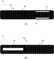
- FIG. 9A is a schematic plan view showing the appearance of the cuff cover 3 according to this modification
- FIG. 9B is an explanatory diagram illustrating a state where the cuff cover 3 according to this modification is attached to the biological information measuring device 100.
- FIG. 9A is a schematic plan view showing the appearance of the cuff cover 3 according to this modification
- FIG. 9B is an explanatory diagram illustrating a state where the cuff cover 3 according to this modification is attached to the biological information measuring device 100.
- the cuff cover 3 according to this modified example has the same basic configuration as the cuff cover 1, such components are denoted by the same reference numerals as the cuff cover 1, and overlapping descriptions are omitted.
- the cuff cover 3 according to this modified example is provided with a fixed portion 31 in which the inner covering portion 10a and the outer covering portion 10b are fixed by, for example, sewing or welding, near the center in the longitudinal direction. It is
- the cuff cover can have various forms according to the form of the biological information measuring device to which it is attached.
- Other embodiments of the cuff cover according to the present invention will be described below with reference to FIGS. 10 and 11.
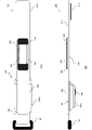
- FIG. 10A is a schematic plan view showing the appearance of the cuff cover 6 according to this embodiment
- FIG. 10B is a schematic bottom view showing the appearance of the cuff cover 6 according to this embodiment
- 11A is a schematic bottom view showing the appearance of the biological information measuring device 110 using the cuff cover 6 according to the present embodiment
- FIG. 11B is a schematic bottom view of the biological information measuring device 110 using the cuff cover 6 according to the present embodiment. It is a schematic side view showing an appearance.
- the cuff cover 6 has the same basic configuration as the cuff cover 1 according to the first embodiment, and has a bag-like covering portion 60 including an inner covering portion 60a and an outer covering portion 60b. is the main component.
- the cuff cover 1 also has electrode openings 61 and 62 in the inner covering portion 60a.
- the outer covering portion 60b is different from the cuff cover 1 in that only one housing opening 63 is provided.
- the configuration of the cuff structure of the biological information measuring device 110 to which the cuff cover 6 is attached is different from that of the biological information measuring device 100 of the first embodiment.
- the main body portion 101, the belt portion 400, and the like are configured in the same manner as in the biological information measuring device 100. Therefore, such components are denoted by the same reference numerals as in the first embodiment. , and further explanation will be omitted.
- the biological information measuring device 110 according to the present embodiment is configured to include only one cuff assembly 300 as a configuration related to the cuff structure.
- the cuff assembly 300 includes a curler 310, a compression cuff 320, a sensing cuff 330, a second electrode 341, a third electrode 342, and a back plate 350, and these components are laminated. In this way, it has an integral structure. Moreover, it has a longitudinal direction as a whole, and is fixed to the housing 101a of the main body at a fixing portion K3.
- the cuff cover 6 according to this embodiment is used to cover such a cuff assembly 300 .
- the curler 310 is a member having a longitudinal direction serving as a base for holding the compression cuff 320, and as shown in FIG.
- the compression cuff 320 is inflated by the air sent from the pump, and has a role of tightening the wrist of the wearing part and applying pressure to an artery (not shown) existing in the wrist.
- the pressure cuff 320 is not placed only on the back side of the wearer's wrist, but has a longitudinal direction on the palm side of the wrist (that is, the sensing cuff 330). outside).
- each function of the sensing cuff 330, the back plate 350, the second electrode 341, and the third electrode 342 is substantially the same as each corresponding configuration of the biological information measuring apparatus 100 of the first embodiment, and thus description thereof is omitted. .
- the longitudinal end portion of the cuff assembly portion 300 on the side where the sensing cuff 330 is located is pushed apart from the housing opening 63 of the cuff cover 6, and the inside of the covering portion 60 is moved. insert into Then, the cuff assembly 300 is inserted along the longitudinal direction of the cuff cover 60, and when the longitudinal end on the side where the sensing cuff 330 is located reaches the end inside the covering portion 60, the opposite end of the covering portion 60 is reached. is pulled toward the other end of the cuff assembly 300 and hooked.
- the housing opening 63 of the outer covering portion 10b is restored to an opening smaller than the area of the cuff assembly 300 when viewed from above due to the stretchability of the covering portion 60. It is stuck at the end.
- the cuff cover 6 according to the present embodiment can be attached to the cuff assembly 300 in this manner, and can be easily removed by performing the procedure in reverse order of attachment.
- the covering portion is formed in the shape of a bag has been described, but the covering portion does not necessarily have to be configured in this way, and the covering portion formed in the form of a sheet allows the cuff structure to be formed. It is also possible to adopt a mode in which only the inner surface is covered.
- the means for attaching the cuff cover is not limited to the housing opening of the covering portion formed in a bag shape, and various means can be used.
- adhesive, double-sided tape, rubber band, surface fastener, snap button, etc. can be adopted.
- the cuff structure has a plurality of electrodes, but the present invention can also be applied to a cuff cover of a biological information measuring device having a cuff structure with only one electrode.
- the present invention can also be applied to a cuff cover of a biological information measuring device worn on other parts of the human body such as the upper arm. .
Landscapes
- Health & Medical Sciences (AREA)
- Life Sciences & Earth Sciences (AREA)
- Engineering & Computer Science (AREA)
- Cardiology (AREA)
- Biomedical Technology (AREA)
- Public Health (AREA)
- Veterinary Medicine (AREA)
- Biophysics (AREA)
- Pathology (AREA)
- Physics & Mathematics (AREA)
- General Health & Medical Sciences (AREA)
- Heart & Thoracic Surgery (AREA)
- Medical Informatics (AREA)
- Molecular Biology (AREA)
- Surgery (AREA)
- Animal Behavior & Ethology (AREA)
- Vascular Medicine (AREA)
- Physiology (AREA)
- Ophthalmology & Optometry (AREA)
- Dentistry (AREA)
- Signal Processing (AREA)
- Measuring Pulse, Heart Rate, Blood Pressure Or Blood Flow (AREA)
- Measurement And Recording Of Electrical Phenomena And Electrical Characteristics Of The Living Body (AREA)
Priority Applications (3)
| Application Number | Priority Date | Filing Date | Title |
|---|---|---|---|
| DE112022002823.8T DE112022002823T5 (de) | 2021-05-28 | 2022-05-06 | Manschettenabdeckung |
| CN202280028706.1A CN117157008A (zh) | 2021-05-28 | 2022-05-06 | 袖带罩 |
| US18/487,747 US20240041338A1 (en) | 2021-05-28 | 2023-10-16 | Cuff cover |
Applications Claiming Priority (2)
| Application Number | Priority Date | Filing Date | Title |
|---|---|---|---|
| JP2021090313A JP7673498B2 (ja) | 2021-05-28 | 2021-05-28 | カフカバー |
| JP2021-090313 | 2021-05-28 |
Related Child Applications (1)
| Application Number | Title | Priority Date | Filing Date |
|---|---|---|---|
| US18/487,747 Continuation US20240041338A1 (en) | 2021-05-28 | 2023-10-16 | Cuff cover |
Publications (1)
| Publication Number | Publication Date |
|---|---|
| WO2022249862A1 true WO2022249862A1 (ja) | 2022-12-01 |
Family
ID=84228736
Family Applications (1)
| Application Number | Title | Priority Date | Filing Date |
|---|---|---|---|
| PCT/JP2022/019550 Ceased WO2022249862A1 (ja) | 2021-05-28 | 2022-05-06 | カフカバー |
Country Status (5)
| Country | Link |
|---|---|
| US (1) | US20240041338A1 (enExample) |
| JP (1) | JP7673498B2 (enExample) |
| CN (1) | CN117157008A (enExample) |
| DE (1) | DE112022002823T5 (enExample) |
| WO (1) | WO2022249862A1 (enExample) |
Citations (5)
| Publication number | Priority date | Publication date | Assignee | Title |
|---|---|---|---|---|
| JP2007195693A (ja) * | 2006-01-25 | 2007-08-09 | Matsushita Electric Works Ltd | 携帯型心電計測装置 |
| JP2014036843A (ja) * | 2012-07-26 | 2014-02-27 | Chang-An Chou | 心血管檢測裝置 |
| JP2018139761A (ja) * | 2017-02-27 | 2018-09-13 | 株式会社テクノ・コモンズ | 生体信号計測装置 |
| WO2020075481A1 (ja) * | 2018-10-12 | 2020-04-16 | 東レ株式会社 | 生体信号モニタリングウェア |
| JP2020103645A (ja) * | 2018-12-27 | 2020-07-09 | オムロンヘルスケア株式会社 | 血圧測定装置用カフカバー |
Family Cites Families (4)
| Publication number | Priority date | Publication date | Assignee | Title |
|---|---|---|---|---|
| WO2003082104A1 (en) | 2002-03-29 | 2003-10-09 | Koninklijke Philips Electronics N.V. | Monitoring system comprising electrodes with projections |
| JP5122252B2 (ja) | 2007-02-15 | 2013-01-16 | 株式会社タニタ | 生体測定装置用カバーシートとその自動配置装置 |
| JP2012251271A (ja) | 2011-06-06 | 2012-12-20 | Makesens:Kk | タッチパネル操作具 |
| JP6332624B2 (ja) * | 2014-06-23 | 2018-05-30 | 株式会社タニタ | 生体電気抵抗測定装置用シート、生体電気抵抗測定装置、方法、及びプログラム |
-
2021
- 2021-05-28 JP JP2021090313A patent/JP7673498B2/ja active Active
-
2022
- 2022-05-06 CN CN202280028706.1A patent/CN117157008A/zh active Pending
- 2022-05-06 DE DE112022002823.8T patent/DE112022002823T5/de active Pending
- 2022-05-06 WO PCT/JP2022/019550 patent/WO2022249862A1/ja not_active Ceased
-
2023
- 2023-10-16 US US18/487,747 patent/US20240041338A1/en active Pending
Patent Citations (5)
| Publication number | Priority date | Publication date | Assignee | Title |
|---|---|---|---|---|
| JP2007195693A (ja) * | 2006-01-25 | 2007-08-09 | Matsushita Electric Works Ltd | 携帯型心電計測装置 |
| JP2014036843A (ja) * | 2012-07-26 | 2014-02-27 | Chang-An Chou | 心血管檢測裝置 |
| JP2018139761A (ja) * | 2017-02-27 | 2018-09-13 | 株式会社テクノ・コモンズ | 生体信号計測装置 |
| WO2020075481A1 (ja) * | 2018-10-12 | 2020-04-16 | 東レ株式会社 | 生体信号モニタリングウェア |
| JP2020103645A (ja) * | 2018-12-27 | 2020-07-09 | オムロンヘルスケア株式会社 | 血圧測定装置用カフカバー |
Also Published As
| Publication number | Publication date |
|---|---|
| JP2022182637A (ja) | 2022-12-08 |
| JP7673498B2 (ja) | 2025-05-09 |
| CN117157008A (zh) | 2023-12-01 |
| US20240041338A1 (en) | 2024-02-08 |
| DE112022002823T5 (de) | 2024-03-07 |
Similar Documents
| Publication | Publication Date | Title |
|---|---|---|
| JP5441977B2 (ja) | 生体情報検出装置 | |
| JP2009240511A (ja) | 生体測定装置 | |
| KR101990383B1 (ko) | 심전도가 측정가능한 혈압 측정 장치 | |
| JPH09238910A (ja) | 手首血圧計のカフ | |
| WO2022249862A1 (ja) | カフカバー | |
| JP3174783U (ja) | 手首式血圧計 | |
| JP3174904U (ja) | 手首式血圧計 | |
| US20250120593A1 (en) | Biometric information measurement device | |
| JP3176530U (ja) | 血圧計 | |
| US20240197189A1 (en) | Biological information measurement device | |
| US20240041337A1 (en) | Blood pressure measurement device | |
| US20240057875A1 (en) | Biological information measurement device | |
| KR101009541B1 (ko) | 생체 신호 측정모듈용 센서 및 이의 제조방법, 그리고 생체신호 측정모듈용 센서를 부착한 의류 | |
| JP7102266B2 (ja) | ベルト及び心電測定装置 | |
| JP6078753B2 (ja) | 四肢装着型生体情報計測装置 | |
| CN207286063U (zh) | 心电检测贴片和穿戴式血压监测装置 | |
| JP2022182637A5 (enExample) | ||
| JPWO2022249459A5 (enExample) | ||
| CN107920756B (zh) | 脉搏波检测装置 | |
| US20240197252A1 (en) | Biological information measurement device | |
| US20250082214A1 (en) | Wrist blood pressure monitor | |
| JP2024090033A (ja) | 血圧測定装置 | |
| JP2020179024A (ja) | 関節不安定性評価用器具、関節不安定性評価用装置及び関節不安定性の評価方法 | |
| JP5658919B2 (ja) | 血圧計 | |
| JP6139871B2 (ja) | 血圧計用カフ |
Legal Events
| Date | Code | Title | Description |
|---|---|---|---|
| 121 | Ep: the epo has been informed by wipo that ep was designated in this application |
Ref document number: 22811136 Country of ref document: EP Kind code of ref document: A1 |
|
| DPE2 | Request for preliminary examination filed before expiration of 19th month from priority date (pct application filed from 20040101) | ||
| WWE | Wipo information: entry into national phase |
Ref document number: 202317067209 Country of ref document: IN |
|
| WWE | Wipo information: entry into national phase |
Ref document number: 112022002823 Country of ref document: DE |
|
| 122 | Ep: pct application non-entry in european phase |
Ref document number: 22811136 Country of ref document: EP Kind code of ref document: A1 |