WO2022249667A1 - 非水電解質蓄電素子及び蓄電装置 - Google Patents
非水電解質蓄電素子及び蓄電装置 Download PDFInfo
- Publication number
- WO2022249667A1 WO2022249667A1 PCT/JP2022/011770 JP2022011770W WO2022249667A1 WO 2022249667 A1 WO2022249667 A1 WO 2022249667A1 JP 2022011770 W JP2022011770 W JP 2022011770W WO 2022249667 A1 WO2022249667 A1 WO 2022249667A1
- Authority
- WO
- WIPO (PCT)
- Prior art keywords
- aqueous electrolyte
- electrode active
- lithium
- positive electrode
- negative electrode
- Prior art date
Links
- 239000011255 nonaqueous electrolyte Substances 0.000 title claims abstract description 97
- 238000003860 storage Methods 0.000 title claims abstract description 85
- OKTJSMMVPCPJKN-UHFFFAOYSA-N Carbon Chemical compound [C] OKTJSMMVPCPJKN-UHFFFAOYSA-N 0.000 claims abstract description 67
- 229910002804 graphite Inorganic materials 0.000 claims abstract description 50
- 239000010439 graphite Substances 0.000 claims abstract description 50
- 229910052723 transition metal Inorganic materials 0.000 claims abstract description 39
- 239000002905 metal composite material Substances 0.000 claims abstract description 36
- 239000011572 manganese Substances 0.000 claims abstract description 33
- 229910052748 manganese Inorganic materials 0.000 claims abstract description 30
- PWHULOQIROXLJO-UHFFFAOYSA-N Manganese Chemical compound [Mn] PWHULOQIROXLJO-UHFFFAOYSA-N 0.000 claims abstract description 26
- 229910052744 lithium Inorganic materials 0.000 claims abstract description 20
- 229910052751 metal Inorganic materials 0.000 claims abstract description 19
- WHXSMMKQMYFTQS-UHFFFAOYSA-N Lithium Chemical compound [Li] WHXSMMKQMYFTQS-UHFFFAOYSA-N 0.000 claims abstract description 13
- PXHVJJICTQNCMI-UHFFFAOYSA-N Nickel Chemical compound [Ni] PXHVJJICTQNCMI-UHFFFAOYSA-N 0.000 claims description 26
- -1 lithium transition metal Chemical class 0.000 claims description 17
- 229910052759 nickel Inorganic materials 0.000 claims description 16
- 229910017052 cobalt Inorganic materials 0.000 claims description 11
- 239000010941 cobalt Substances 0.000 claims description 11
- GUTLYIVDDKVIGB-UHFFFAOYSA-N cobalt atom Chemical compound [Co] GUTLYIVDDKVIGB-UHFFFAOYSA-N 0.000 claims description 11
- WPBNNNQJVZRUHP-UHFFFAOYSA-L manganese(2+);methyl n-[[2-(methoxycarbonylcarbamothioylamino)phenyl]carbamothioyl]carbamate;n-[2-(sulfidocarbothioylamino)ethyl]carbamodithioate Chemical compound [Mn+2].[S-]C(=S)NCCNC([S-])=S.COC(=O)NC(=S)NC1=CC=CC=C1NC(=S)NC(=O)OC WPBNNNQJVZRUHP-UHFFFAOYSA-L 0.000 abstract description 5
- 239000007773 negative electrode material Substances 0.000 description 50
- 239000007774 positive electrode material Substances 0.000 description 50
- 230000014759 maintenance of location Effects 0.000 description 24
- 239000000463 material Substances 0.000 description 24
- 238000007600 charging Methods 0.000 description 21
- 239000002245 particle Substances 0.000 description 19
- 239000000758 substrate Substances 0.000 description 17
- 239000006258 conductive agent Substances 0.000 description 14
- 238000000034 method Methods 0.000 description 14
- 239000011230 binding agent Substances 0.000 description 13
- 229910052782 aluminium Inorganic materials 0.000 description 11
- 230000005611 electricity Effects 0.000 description 10
- XAGFODPZIPBFFR-UHFFFAOYSA-N aluminium Chemical compound [Al] XAGFODPZIPBFFR-UHFFFAOYSA-N 0.000 description 9
- HBBGRARXTFLTSG-UHFFFAOYSA-N Lithium ion Chemical compound [Li+] HBBGRARXTFLTSG-UHFFFAOYSA-N 0.000 description 8
- 239000003125 aqueous solvent Substances 0.000 description 8
- 239000003575 carbonaceous material Substances 0.000 description 8
- 150000005678 chain carbonates Chemical class 0.000 description 8
- 150000005676 cyclic carbonates Chemical class 0.000 description 8
- 239000011888 foil Substances 0.000 description 8
- 229910001416 lithium ion Inorganic materials 0.000 description 8
- 229920000642 polymer Polymers 0.000 description 8
- 239000002562 thickening agent Substances 0.000 description 8
- RYGMFSIKBFXOCR-UHFFFAOYSA-N Copper Chemical compound [Cu] RYGMFSIKBFXOCR-UHFFFAOYSA-N 0.000 description 7
- 239000000945 filler Substances 0.000 description 7
- 238000004519 manufacturing process Methods 0.000 description 7
- 239000007784 solid electrolyte Substances 0.000 description 7
- 239000002033 PVDF binder Substances 0.000 description 6
- 239000003990 capacitor Substances 0.000 description 6
- 239000003792 electrolyte Substances 0.000 description 6
- 229920002981 polyvinylidene fluoride Polymers 0.000 description 6
- 150000003839 salts Chemical class 0.000 description 6
- VYPSYNLAJGMNEJ-UHFFFAOYSA-N Silicium dioxide Chemical compound O=[Si]=O VYPSYNLAJGMNEJ-UHFFFAOYSA-N 0.000 description 5
- 239000006230 acetylene black Substances 0.000 description 5
- 239000000654 additive Substances 0.000 description 5
- 229910052796 boron Inorganic materials 0.000 description 5
- 229910052799 carbon Inorganic materials 0.000 description 5
- 150000001875 compounds Chemical class 0.000 description 5
- 239000011889 copper foil Substances 0.000 description 5
- 239000013078 crystal Substances 0.000 description 5
- HNPSIPDUKPIQMN-UHFFFAOYSA-N dioxosilane;oxo(oxoalumanyloxy)alumane Chemical compound O=[Si]=O.O=[Al]O[Al]=O HNPSIPDUKPIQMN-UHFFFAOYSA-N 0.000 description 5
- 238000007599 discharging Methods 0.000 description 5
- 229910003002 lithium salt Inorganic materials 0.000 description 5
- 159000000002 lithium salts Chemical class 0.000 description 5
- 239000000203 mixture Substances 0.000 description 5
- 239000000843 powder Substances 0.000 description 5
- 229920005989 resin Polymers 0.000 description 5
- 239000011347 resin Substances 0.000 description 5
- VTYYLEPIZMXCLO-UHFFFAOYSA-L Calcium carbonate Chemical compound [Ca+2].[O-]C([O-])=O VTYYLEPIZMXCLO-UHFFFAOYSA-L 0.000 description 4
- KMTRUDSVKNLOMY-UHFFFAOYSA-N Ethylene carbonate Chemical compound O=C1OCCO1 KMTRUDSVKNLOMY-UHFFFAOYSA-N 0.000 description 4
- QVQLCTNNEUAWMS-UHFFFAOYSA-N barium oxide Chemical compound [Ba]=O QVQLCTNNEUAWMS-UHFFFAOYSA-N 0.000 description 4
- TZCXTZWJZNENPQ-UHFFFAOYSA-L barium sulfate Chemical compound [Ba+2].[O-]S([O-])(=O)=O TZCXTZWJZNENPQ-UHFFFAOYSA-L 0.000 description 4
- 239000006229 carbon black Substances 0.000 description 4
- 239000002131 composite material Substances 0.000 description 4
- 229910052802 copper Inorganic materials 0.000 description 4
- 239000010949 copper Substances 0.000 description 4
- JBTWLSYIZRCDFO-UHFFFAOYSA-N ethyl methyl carbonate Chemical compound CCOC(=O)OC JBTWLSYIZRCDFO-UHFFFAOYSA-N 0.000 description 4
- 150000002484 inorganic compounds Chemical class 0.000 description 4
- 229910010272 inorganic material Inorganic materials 0.000 description 4
- 239000002184 metal Substances 0.000 description 4
- 238000010298 pulverizing process Methods 0.000 description 4
- 238000006722 reduction reaction Methods 0.000 description 4
- IATRAKWUXMZMIY-UHFFFAOYSA-N strontium oxide Chemical compound [O-2].[Sr+2] IATRAKWUXMZMIY-UHFFFAOYSA-N 0.000 description 4
- 239000000126 substance Substances 0.000 description 4
- 238000012360 testing method Methods 0.000 description 4
- 229910052721 tungsten Inorganic materials 0.000 description 4
- VAYTZRYEBVHVLE-UHFFFAOYSA-N 1,3-dioxol-2-one Chemical compound O=C1OC=CO1 VAYTZRYEBVHVLE-UHFFFAOYSA-N 0.000 description 3
- 229910000838 Al alloy Inorganic materials 0.000 description 3
- ZOXJGFHDIHLPTG-UHFFFAOYSA-N Boron Chemical compound [B] ZOXJGFHDIHLPTG-UHFFFAOYSA-N 0.000 description 3
- 229920002134 Carboxymethyl cellulose Polymers 0.000 description 3
- 229920002943 EPDM rubber Polymers 0.000 description 3
- 239000004698 Polyethylene Substances 0.000 description 3
- 239000004743 Polypropylene Substances 0.000 description 3
- GWEVSGVZZGPLCZ-UHFFFAOYSA-N Titan oxide Chemical compound O=[Ti]=O GWEVSGVZZGPLCZ-UHFFFAOYSA-N 0.000 description 3
- 239000011149 active material Substances 0.000 description 3
- 229910000323 aluminium silicate Inorganic materials 0.000 description 3
- 229910021393 carbon nanotube Inorganic materials 0.000 description 3
- 239000002041 carbon nanotube Substances 0.000 description 3
- 238000004891 communication Methods 0.000 description 3
- 238000012790 confirmation Methods 0.000 description 3
- 238000010277 constant-current charging Methods 0.000 description 3
- 229910052731 fluorine Inorganic materials 0.000 description 3
- 229910021389 graphene Inorganic materials 0.000 description 3
- 150000002739 metals Chemical class 0.000 description 3
- VLKZOEOYAKHREP-UHFFFAOYSA-N n-Hexane Chemical compound CCCCCC VLKZOEOYAKHREP-UHFFFAOYSA-N 0.000 description 3
- 239000004745 nonwoven fabric Substances 0.000 description 3
- 229920000573 polyethylene Polymers 0.000 description 3
- 229920000098 polyolefin Polymers 0.000 description 3
- 229920001155 polypropylene Polymers 0.000 description 3
- 238000003825 pressing Methods 0.000 description 3
- 239000007787 solid Substances 0.000 description 3
- 229920003048 styrene butadiene rubber Polymers 0.000 description 3
- 229910052719 titanium Inorganic materials 0.000 description 3
- 239000010936 titanium Substances 0.000 description 3
- ZZXUZKXVROWEIF-UHFFFAOYSA-N 1,2-butylene carbonate Chemical compound CCC1COC(=O)O1 ZZXUZKXVROWEIF-UHFFFAOYSA-N 0.000 description 2
- ZPFAVCIQZKRBGF-UHFFFAOYSA-N 1,3,2-dioxathiolane 2,2-dioxide Chemical compound O=S1(=O)OCCO1 ZPFAVCIQZKRBGF-UHFFFAOYSA-N 0.000 description 2
- YJTKZCDBKVTVBY-UHFFFAOYSA-N 1,3-Diphenylbenzene Chemical group C1=CC=CC=C1C1=CC=CC(C=2C=CC=CC=2)=C1 YJTKZCDBKVTVBY-UHFFFAOYSA-N 0.000 description 2
- BJWMSGRKJIOCNR-UHFFFAOYSA-N 4-ethenyl-1,3-dioxolan-2-one Chemical compound C=CC1COC(=O)O1 BJWMSGRKJIOCNR-UHFFFAOYSA-N 0.000 description 2
- SBLRHMKNNHXPHG-UHFFFAOYSA-N 4-fluoro-1,3-dioxolan-2-one Chemical compound FC1COC(=O)O1 SBLRHMKNNHXPHG-UHFFFAOYSA-N 0.000 description 2
- 239000005995 Aluminium silicate Substances 0.000 description 2
- 229910000881 Cu alloy Inorganic materials 0.000 description 2
- OIFBSDVPJOWBCH-UHFFFAOYSA-N Diethyl carbonate Chemical compound CCOC(=O)OCC OIFBSDVPJOWBCH-UHFFFAOYSA-N 0.000 description 2
- IAZDPXIOMUYVGZ-UHFFFAOYSA-N Dimethylsulphoxide Chemical compound CS(C)=O IAZDPXIOMUYVGZ-UHFFFAOYSA-N 0.000 description 2
- GUUVPOWQJOLRAS-UHFFFAOYSA-N Diphenyl disulfide Chemical compound C=1C=CC=CC=1SSC1=CC=CC=C1 GUUVPOWQJOLRAS-UHFFFAOYSA-N 0.000 description 2
- UQSXHKLRYXJYBZ-UHFFFAOYSA-N Iron oxide Chemical compound [Fe]=O UQSXHKLRYXJYBZ-UHFFFAOYSA-N 0.000 description 2
- 229910012851 LiCoO 2 Inorganic materials 0.000 description 2
- 229910013870 LiPF 6 Inorganic materials 0.000 description 2
- SECXISVLQFMRJM-UHFFFAOYSA-N N-Methylpyrrolidone Chemical compound CN1CCCC1=O SECXISVLQFMRJM-UHFFFAOYSA-N 0.000 description 2
- 229910021314 NaFeO 2 Inorganic materials 0.000 description 2
- 239000004642 Polyimide Substances 0.000 description 2
- 241000156302 Porcine hemagglutinating encephalomyelitis virus Species 0.000 description 2
- 229910052581 Si3N4 Inorganic materials 0.000 description 2
- RTAQQCXQSZGOHL-UHFFFAOYSA-N Titanium Chemical compound [Ti] RTAQQCXQSZGOHL-UHFFFAOYSA-N 0.000 description 2
- 229910021536 Zeolite Inorganic materials 0.000 description 2
- 230000000996 additive effect Effects 0.000 description 2
- 229910045601 alloy Inorganic materials 0.000 description 2
- 239000000956 alloy Substances 0.000 description 2
- 235000012211 aluminium silicate Nutrition 0.000 description 2
- 229910052586 apatite Inorganic materials 0.000 description 2
- 239000012300 argon atmosphere Substances 0.000 description 2
- 150000001491 aromatic compounds Chemical class 0.000 description 2
- 229910021383 artificial graphite Inorganic materials 0.000 description 2
- QVGXLLKOCUKJST-UHFFFAOYSA-N atomic oxygen Chemical compound [O] QVGXLLKOCUKJST-UHFFFAOYSA-N 0.000 description 2
- 229910052788 barium Inorganic materials 0.000 description 2
- OYLGJCQECKOTOL-UHFFFAOYSA-L barium fluoride Chemical compound [F-].[F-].[Ba+2] OYLGJCQECKOTOL-UHFFFAOYSA-L 0.000 description 2
- 229910001632 barium fluoride Inorganic materials 0.000 description 2
- 239000000440 bentonite Substances 0.000 description 2
- 229910000278 bentonite Inorganic materials 0.000 description 2
- SVPXDRXYRYOSEX-UHFFFAOYSA-N bentoquatam Chemical compound O.O=[Si]=O.O=[Al]O[Al]=O SVPXDRXYRYOSEX-UHFFFAOYSA-N 0.000 description 2
- 229910052794 bromium Inorganic materials 0.000 description 2
- 229910052791 calcium Inorganic materials 0.000 description 2
- 239000011575 calcium Substances 0.000 description 2
- 229910000019 calcium carbonate Inorganic materials 0.000 description 2
- WUKWITHWXAAZEY-UHFFFAOYSA-L calcium difluoride Chemical compound [F-].[F-].[Ca+2] WUKWITHWXAAZEY-UHFFFAOYSA-L 0.000 description 2
- 229910001634 calcium fluoride Inorganic materials 0.000 description 2
- BRPQOXSCLDDYGP-UHFFFAOYSA-N calcium oxide Chemical compound [O-2].[Ca+2] BRPQOXSCLDDYGP-UHFFFAOYSA-N 0.000 description 2
- 239000000292 calcium oxide Substances 0.000 description 2
- ODINCKMPIJJUCX-UHFFFAOYSA-N calcium oxide Inorganic materials [Ca]=O ODINCKMPIJJUCX-UHFFFAOYSA-N 0.000 description 2
- 150000004649 carbonic acid derivatives Chemical class 0.000 description 2
- 229910052801 chlorine Inorganic materials 0.000 description 2
- 229910052804 chromium Inorganic materials 0.000 description 2
- 239000011651 chromium Substances 0.000 description 2
- 230000000052 comparative effect Effects 0.000 description 2
- PMHQVHHXPFUNSP-UHFFFAOYSA-M copper(1+);methylsulfanylmethane;bromide Chemical compound Br[Cu].CSC PMHQVHHXPFUNSP-UHFFFAOYSA-M 0.000 description 2
- 238000005336 cracking Methods 0.000 description 2
- 238000013461 design Methods 0.000 description 2
- TXCDCPKCNAJMEE-UHFFFAOYSA-N dibenzofuran Chemical compound C1=CC=C2C3=CC=CC=C3OC2=C1 TXCDCPKCNAJMEE-UHFFFAOYSA-N 0.000 description 2
- IEJIGPNLZYLLBP-UHFFFAOYSA-N dimethyl carbonate Chemical compound COC(=O)OC IEJIGPNLZYLLBP-UHFFFAOYSA-N 0.000 description 2
- KZHJGOXRZJKJNY-UHFFFAOYSA-N dioxosilane;oxo(oxoalumanyloxy)alumane Chemical compound O=[Si]=O.O=[Si]=O.O=[Al]O[Al]=O.O=[Al]O[Al]=O.O=[Al]O[Al]=O KZHJGOXRZJKJNY-UHFFFAOYSA-N 0.000 description 2
- ZUOUZKKEUPVFJK-UHFFFAOYSA-N diphenyl Chemical compound C1=CC=CC=C1C1=CC=CC=C1 ZUOUZKKEUPVFJK-UHFFFAOYSA-N 0.000 description 2
- USIUVYZYUHIAEV-UHFFFAOYSA-N diphenyl ether Chemical compound C=1C=CC=CC=1OC1=CC=CC=C1 USIUVYZYUHIAEV-UHFFFAOYSA-N 0.000 description 2
- 239000002612 dispersion medium Substances 0.000 description 2
- 238000009826 distribution Methods 0.000 description 2
- 125000000524 functional group Chemical group 0.000 description 2
- 229910052733 gallium Inorganic materials 0.000 description 2
- 229910052732 germanium Inorganic materials 0.000 description 2
- 150000004676 glycans Chemical class 0.000 description 2
- 229910052500 inorganic mineral Inorganic materials 0.000 description 2
- 229910052740 iodine Inorganic materials 0.000 description 2
- 229910052742 iron Inorganic materials 0.000 description 2
- XEEYBQQBJWHFJM-UHFFFAOYSA-N iron Substances [Fe] XEEYBQQBJWHFJM-UHFFFAOYSA-N 0.000 description 2
- NLYAJNPCOHFWQQ-UHFFFAOYSA-N kaolin Chemical compound O.O.O=[Al]O[Si](=O)O[Si](=O)O[Al]=O NLYAJNPCOHFWQQ-UHFFFAOYSA-N 0.000 description 2
- 229910052749 magnesium Inorganic materials 0.000 description 2
- 239000011777 magnesium Substances 0.000 description 2
- 239000000395 magnesium oxide Substances 0.000 description 2
- CPLXHLVBOLITMK-UHFFFAOYSA-N magnesium oxide Inorganic materials [Mg]=O CPLXHLVBOLITMK-UHFFFAOYSA-N 0.000 description 2
- AXZKOIWUVFPNLO-UHFFFAOYSA-N magnesium;oxygen(2-) Chemical compound [O-2].[Mg+2] AXZKOIWUVFPNLO-UHFFFAOYSA-N 0.000 description 2
- QSHDDOUJBYECFT-UHFFFAOYSA-N mercury Chemical compound [Hg] QSHDDOUJBYECFT-UHFFFAOYSA-N 0.000 description 2
- 229910052753 mercury Inorganic materials 0.000 description 2
- VNWKTOKETHGBQD-UHFFFAOYSA-N methane Chemical compound C VNWKTOKETHGBQD-UHFFFAOYSA-N 0.000 description 2
- 239000010445 mica Substances 0.000 description 2
- 229910052618 mica group Inorganic materials 0.000 description 2
- 239000011707 mineral Substances 0.000 description 2
- 229910052750 molybdenum Inorganic materials 0.000 description 2
- 229910052863 mullite Inorganic materials 0.000 description 2
- 229910052758 niobium Inorganic materials 0.000 description 2
- 150000004767 nitrides Chemical class 0.000 description 2
- 229910052757 nitrogen Inorganic materials 0.000 description 2
- 239000010450 olivine Substances 0.000 description 2
- 229910052609 olivine Inorganic materials 0.000 description 2
- TWNQGVIAIRXVLR-UHFFFAOYSA-N oxo(oxoalumanyloxy)alumane Chemical compound O=[Al]O[Al]=O TWNQGVIAIRXVLR-UHFFFAOYSA-N 0.000 description 2
- 229910052760 oxygen Inorganic materials 0.000 description 2
- 239000001301 oxygen Substances 0.000 description 2
- VSIIXMUUUJUKCM-UHFFFAOYSA-D pentacalcium;fluoride;triphosphate Chemical compound [F-].[Ca+2].[Ca+2].[Ca+2].[Ca+2].[Ca+2].[O-]P([O-])([O-])=O.[O-]P([O-])([O-])=O.[O-]P([O-])([O-])=O VSIIXMUUUJUKCM-UHFFFAOYSA-D 0.000 description 2
- 229910052698 phosphorus Inorganic materials 0.000 description 2
- 229920001721 polyimide Polymers 0.000 description 2
- 229920001282 polysaccharide Polymers 0.000 description 2
- 239000005017 polysaccharide Substances 0.000 description 2
- 229920001343 polytetrafluoroethylene Polymers 0.000 description 2
- 239000004810 polytetrafluoroethylene Substances 0.000 description 2
- 239000011148 porous material Substances 0.000 description 2
- 229910052700 potassium Inorganic materials 0.000 description 2
- 238000002360 preparation method Methods 0.000 description 2
- RUOJZAUFBMNUDX-UHFFFAOYSA-N propylene carbonate Chemical compound CC1COC(=O)O1 RUOJZAUFBMNUDX-UHFFFAOYSA-N 0.000 description 2
- 229910052706 scandium Inorganic materials 0.000 description 2
- HQVNEWCFYHHQES-UHFFFAOYSA-N silicon nitride Chemical compound N12[Si]34N5[Si]62N3[Si]51N64 HQVNEWCFYHHQES-UHFFFAOYSA-N 0.000 description 2
- 229910052814 silicon oxide Inorganic materials 0.000 description 2
- 229910052708 sodium Inorganic materials 0.000 description 2
- 239000002904 solvent Substances 0.000 description 2
- 239000011029 spinel Substances 0.000 description 2
- 229910052596 spinel Inorganic materials 0.000 description 2
- 239000010935 stainless steel Substances 0.000 description 2
- 229910001220 stainless steel Inorganic materials 0.000 description 2
- 229910052712 strontium Inorganic materials 0.000 description 2
- 239000002203 sulfidic glass Substances 0.000 description 2
- HHVIBTZHLRERCL-UHFFFAOYSA-N sulfonyldimethane Chemical compound CS(C)(=O)=O HHVIBTZHLRERCL-UHFFFAOYSA-N 0.000 description 2
- 229910052715 tantalum Inorganic materials 0.000 description 2
- YTZKOQUCBOVLHL-UHFFFAOYSA-N tert-butylbenzene Chemical compound CC(C)(C)C1=CC=CC=C1 YTZKOQUCBOVLHL-UHFFFAOYSA-N 0.000 description 2
- 229910052718 tin Inorganic materials 0.000 description 2
- WFKWXMTUELFFGS-UHFFFAOYSA-N tungsten Chemical compound [W] WFKWXMTUELFFGS-UHFFFAOYSA-N 0.000 description 2
- 239000010937 tungsten Substances 0.000 description 2
- 229910052720 vanadium Inorganic materials 0.000 description 2
- XLYOFNOQVPJJNP-UHFFFAOYSA-N water Substances O XLYOFNOQVPJJNP-UHFFFAOYSA-N 0.000 description 2
- 239000010457 zeolite Substances 0.000 description 2
- 229910052725 zinc Inorganic materials 0.000 description 2
- 229910052726 zirconium Inorganic materials 0.000 description 2
- VSKCGJBMHRNFCZ-UHFFFAOYSA-N (2,2-dioxo-1,3,2-dioxathiolan-4-yl)methyl methanesulfonate Chemical compound CS(=O)(=O)OCC1COS(=O)(=O)O1 VSKCGJBMHRNFCZ-UHFFFAOYSA-N 0.000 description 1
- WDXYVJKNSMILOQ-UHFFFAOYSA-N 1,3,2-dioxathiolane 2-oxide Chemical compound O=S1OCCO1 WDXYVJKNSMILOQ-UHFFFAOYSA-N 0.000 description 1
- FSSPGSAQUIYDCN-UHFFFAOYSA-N 1,3-Propane sultone Chemical compound O=S1(=O)CCCO1 FSSPGSAQUIYDCN-UHFFFAOYSA-N 0.000 description 1
- IOBWAHRFIPQEQL-UHFFFAOYSA-N 1,3-difluoro-2-methoxybenzene Chemical compound COC1=C(F)C=CC=C1F IOBWAHRFIPQEQL-UHFFFAOYSA-N 0.000 description 1
- OTGQPYSISUUHAF-UHFFFAOYSA-N 1,3-difluoro-5-methoxybenzene Chemical compound COC1=CC(F)=CC(F)=C1 OTGQPYSISUUHAF-UHFFFAOYSA-N 0.000 description 1
- HUDMAQLYMUKZOZ-UHFFFAOYSA-N 1,4-difluoro-2-methoxybenzene Chemical compound COC1=CC(F)=CC=C1F HUDMAQLYMUKZOZ-UHFFFAOYSA-N 0.000 description 1
- GUYHXQLLIISBQF-UHFFFAOYSA-N 1-cyclohexyl-2-fluorobenzene Chemical compound FC1=CC=CC=C1C1CCCCC1 GUYHXQLLIISBQF-UHFFFAOYSA-N 0.000 description 1
- YAOIFBJJGFYYFI-UHFFFAOYSA-N 1-cyclohexyl-4-fluorobenzene Chemical compound C1=CC(F)=CC=C1C1CCCCC1 YAOIFBJJGFYYFI-UHFFFAOYSA-N 0.000 description 1
- MBDUIEKYVPVZJH-UHFFFAOYSA-N 1-ethylsulfonylethane Chemical compound CCS(=O)(=O)CC MBDUIEKYVPVZJH-UHFFFAOYSA-N 0.000 description 1
- KLECYOQFQXJYBC-UHFFFAOYSA-N 1-fluoro-2-phenylbenzene Chemical group FC1=CC=CC=C1C1=CC=CC=C1 KLECYOQFQXJYBC-UHFFFAOYSA-N 0.000 description 1
- CRMJLJFDPNJIQA-UHFFFAOYSA-N 2,4-difluoro-1-methoxybenzene Chemical compound COC1=CC=C(F)C=C1F CRMJLJFDPNJIQA-UHFFFAOYSA-N 0.000 description 1
- FALRKNHUBBKYCC-UHFFFAOYSA-N 2-(chloromethyl)pyridine-3-carbonitrile Chemical compound ClCC1=NC=CC=C1C#N FALRKNHUBBKYCC-UHFFFAOYSA-N 0.000 description 1
- QHTJSSMHBLGUHV-UHFFFAOYSA-N 2-methylbutan-2-ylbenzene Chemical compound CCC(C)(C)C1=CC=CC=C1 QHTJSSMHBLGUHV-UHFFFAOYSA-N 0.000 description 1
- IFDLFCDWOFLKEB-UHFFFAOYSA-N 2-methylbutylbenzene Chemical compound CCC(C)CC1=CC=CC=C1 IFDLFCDWOFLKEB-UHFFFAOYSA-N 0.000 description 1
- HHCHLHOEAKKCAB-UHFFFAOYSA-N 2-oxaspiro[3.5]nonane-1,3-dione Chemical compound O=C1OC(=O)C11CCCCC1 HHCHLHOEAKKCAB-UHFFFAOYSA-N 0.000 description 1
- SYIUWAVTBADRJG-UHFFFAOYSA-N 2H-pyran-2,6(3H)-dione Chemical compound O=C1CC=CC(=O)O1 SYIUWAVTBADRJG-UHFFFAOYSA-N 0.000 description 1
- NIDAYXQNTRODPA-UHFFFAOYSA-N 3,3,3-trifluoropropyl hydrogen carbonate Chemical compound OC(=O)OCCC(F)(F)F NIDAYXQNTRODPA-UHFFFAOYSA-N 0.000 description 1
- AYKYXWQEBUNJCN-UHFFFAOYSA-N 3-methylfuran-2,5-dione Chemical compound CC1=CC(=O)OC1=O AYKYXWQEBUNJCN-UHFFFAOYSA-N 0.000 description 1
- OFNISBHGPNMTMS-UHFFFAOYSA-N 3-methylideneoxolane-2,5-dione Chemical compound C=C1CC(=O)OC1=O OFNISBHGPNMTMS-UHFFFAOYSA-N 0.000 description 1
- DSMUTQTWFHVVGQ-UHFFFAOYSA-N 4,5-difluoro-1,3-dioxolan-2-one Chemical compound FC1OC(=O)OC1F DSMUTQTWFHVVGQ-UHFFFAOYSA-N 0.000 description 1
- SROHGOJDCAODGI-UHFFFAOYSA-N 4,5-diphenyl-1,3-dioxol-2-one Chemical compound O1C(=O)OC(C=2C=CC=CC=2)=C1C1=CC=CC=C1 SROHGOJDCAODGI-UHFFFAOYSA-N 0.000 description 1
- OYOKPDLAMOMTEE-UHFFFAOYSA-N 4-chloro-1,3-dioxolan-2-one Chemical compound ClC1COC(=O)O1 OYOKPDLAMOMTEE-UHFFFAOYSA-N 0.000 description 1
- SJHAYVFVKRXMKG-UHFFFAOYSA-N 4-methyl-1,3,2-dioxathiolane 2-oxide Chemical compound CC1COS(=O)O1 SJHAYVFVKRXMKG-UHFFFAOYSA-N 0.000 description 1
- VMAJRFCXVOIAAS-UHFFFAOYSA-N 4-phenyl-1,3-dioxol-2-one Chemical compound O1C(=O)OC=C1C1=CC=CC=C1 VMAJRFCXVOIAAS-UHFFFAOYSA-N 0.000 description 1
- ZKOGUIGAVNCCKH-UHFFFAOYSA-N 4-phenyl-1,3-dioxolan-2-one Chemical compound O1C(=O)OCC1C1=CC=CC=C1 ZKOGUIGAVNCCKH-UHFFFAOYSA-N 0.000 description 1
- BTBUEUYNUDRHOZ-UHFFFAOYSA-N Borate Chemical compound [O-]B([O-])[O-] BTBUEUYNUDRHOZ-UHFFFAOYSA-N 0.000 description 1
- COVZYZSDYWQREU-UHFFFAOYSA-N Busulfan Chemical compound CS(=O)(=O)OCCCCOS(C)(=O)=O COVZYZSDYWQREU-UHFFFAOYSA-N 0.000 description 1
- XMWRBQBLMFGWIX-UHFFFAOYSA-N C60 fullerene Chemical compound C12=C3C(C4=C56)=C7C8=C5C5=C9C%10=C6C6=C4C1=C1C4=C6C6=C%10C%10=C9C9=C%11C5=C8C5=C8C7=C3C3=C7C2=C1C1=C2C4=C6C4=C%10C6=C9C9=C%11C5=C5C8=C3C3=C7C1=C1C2=C4C6=C2C9=C5C3=C12 XMWRBQBLMFGWIX-UHFFFAOYSA-N 0.000 description 1
- 229920000049 Carbon (fiber) Polymers 0.000 description 1
- BWGNESOTFCXPMA-UHFFFAOYSA-N Dihydrogen disulfide Chemical compound SS BWGNESOTFCXPMA-UHFFFAOYSA-N 0.000 description 1
- YCKRFDGAMUMZLT-UHFFFAOYSA-N Fluorine atom Chemical compound [F] YCKRFDGAMUMZLT-UHFFFAOYSA-N 0.000 description 1
- 229910005933 Ge—P Inorganic materials 0.000 description 1
- 229910013063 LiBF 4 Inorganic materials 0.000 description 1
- 229910013375 LiC Inorganic materials 0.000 description 1
- 229910013684 LiClO 4 Inorganic materials 0.000 description 1
- 229910013131 LiN Inorganic materials 0.000 description 1
- 229910013528 LiN(SO2 CF3)2 Inorganic materials 0.000 description 1
- 229910013385 LiN(SO2C2F5)2 Inorganic materials 0.000 description 1
- 229910013392 LiN(SO2CF3)(SO2C4F9) Inorganic materials 0.000 description 1
- 229910013716 LiNi Inorganic materials 0.000 description 1
- 229910001290 LiPF6 Inorganic materials 0.000 description 1
- 229910012258 LiPO Inorganic materials 0.000 description 1
- 229910001228 Li[Ni1/3Co1/3Mn1/3]O2 (NCM 111) Inorganic materials 0.000 description 1
- SXDASMFNTHIRRS-UHFFFAOYSA-M P(=O)([O-])(F)F.C(C(=O)O)(=O)O.C(C(=O)O)(=O)O.[Li+] Chemical compound P(=O)([O-])(F)F.C(C(=O)O)(=O)O.C(C(=O)O)(=O)O.[Li+] SXDASMFNTHIRRS-UHFFFAOYSA-M 0.000 description 1
- 229910019142 PO4 Inorganic materials 0.000 description 1
- 229920003171 Poly (ethylene oxide) Polymers 0.000 description 1
- 229910000831 Steel Inorganic materials 0.000 description 1
- 239000002174 Styrene-butadiene Substances 0.000 description 1
- 238000002441 X-ray diffraction Methods 0.000 description 1
- SYRDSFGUUQPYOB-UHFFFAOYSA-N [Li+].[Li+].[Li+].[O-]B([O-])[O-].FC(=O)C(F)=O Chemical compound [Li+].[Li+].[Li+].[O-]B([O-])[O-].FC(=O)C(F)=O SYRDSFGUUQPYOB-UHFFFAOYSA-N 0.000 description 1
- PNEYBMLMFCGWSK-UHFFFAOYSA-N aluminium oxide Inorganic materials [O-2].[O-2].[O-2].[Al+3].[Al+3] PNEYBMLMFCGWSK-UHFFFAOYSA-N 0.000 description 1
- 150000001408 amides Chemical class 0.000 description 1
- RDOXTESZEPMUJZ-UHFFFAOYSA-N anisole Chemical class COC1=CC=CC=C1 RDOXTESZEPMUJZ-UHFFFAOYSA-N 0.000 description 1
- 239000004760 aramid Substances 0.000 description 1
- 229920003235 aromatic polyamide Polymers 0.000 description 1
- 239000012298 atmosphere Substances 0.000 description 1
- JRPBQTZRNDNNOP-UHFFFAOYSA-N barium titanate Chemical compound [Ba+2].[Ba+2].[O-][Ti]([O-])([O-])[O-] JRPBQTZRNDNNOP-UHFFFAOYSA-N 0.000 description 1
- 229910002113 barium titanate Inorganic materials 0.000 description 1
- 235000010290 biphenyl Nutrition 0.000 description 1
- 239000004305 biphenyl Substances 0.000 description 1
- WLLOZRDOFANZMZ-UHFFFAOYSA-N bis(2,2,2-trifluoroethyl) carbonate Chemical compound FC(F)(F)COC(=O)OCC(F)(F)F WLLOZRDOFANZMZ-UHFFFAOYSA-N 0.000 description 1
- 229910001593 boehmite Inorganic materials 0.000 description 1
- 229960002092 busulfan Drugs 0.000 description 1
- ZTCLFSRIWSZUHZ-UHFFFAOYSA-N but-1-yne;carbonic acid Chemical compound CCC#C.OC(O)=O ZTCLFSRIWSZUHZ-UHFFFAOYSA-N 0.000 description 1
- AXCZMVOFGPJBDE-UHFFFAOYSA-L calcium dihydroxide Chemical compound [OH-].[OH-].[Ca+2] AXCZMVOFGPJBDE-UHFFFAOYSA-L 0.000 description 1
- 239000000920 calcium hydroxide Substances 0.000 description 1
- 229910001861 calcium hydroxide Inorganic materials 0.000 description 1
- 239000004917 carbon fiber Substances 0.000 description 1
- 239000002134 carbon nanofiber Substances 0.000 description 1
- SYLNJGIBLUVXCG-UHFFFAOYSA-N carbonic acid;prop-1-yne Chemical compound CC#C.OC(O)=O SYLNJGIBLUVXCG-UHFFFAOYSA-N 0.000 description 1
- 239000001768 carboxy methyl cellulose Substances 0.000 description 1
- 235000010948 carboxy methyl cellulose Nutrition 0.000 description 1
- 150000001733 carboxylic acid esters Chemical class 0.000 description 1
- 239000008112 carboxymethyl-cellulose Substances 0.000 description 1
- 239000000919 ceramic Substances 0.000 description 1
- 239000003795 chemical substances by application Substances 0.000 description 1
- 239000011248 coating agent Substances 0.000 description 1
- 238000000576 coating method Methods 0.000 description 1
- 239000004020 conductor Substances 0.000 description 1
- 238000010280 constant potential charging Methods 0.000 description 1
- 230000008602 contraction Effects 0.000 description 1
- HHNHBFLGXIUXCM-GFCCVEGCSA-N cyclohexylbenzene Chemical compound [CH]1CCCC[C@@H]1C1=CC=CC=C1 HHNHBFLGXIUXCM-GFCCVEGCSA-N 0.000 description 1
- 238000010586 diagram Methods 0.000 description 1
- GUJOJGAPFQRJSV-UHFFFAOYSA-N dialuminum;dioxosilane;oxygen(2-);hydrate Chemical compound O.[O-2].[O-2].[O-2].[Al+3].[Al+3].O=[Si]=O.O=[Si]=O.O=[Si]=O.O=[Si]=O GUJOJGAPFQRJSV-UHFFFAOYSA-N 0.000 description 1
- 229910003460 diamond Inorganic materials 0.000 description 1
- 239000010432 diamond Substances 0.000 description 1
- CCAFPWNGIUBUSD-UHFFFAOYSA-N diethyl sulfoxide Chemical compound CCS(=O)CC CCAFPWNGIUBUSD-UHFFFAOYSA-N 0.000 description 1
- YNQRWVCLAIUHHI-UHFFFAOYSA-L dilithium;oxalate Chemical class [Li+].[Li+].[O-]C(=O)C([O-])=O YNQRWVCLAIUHHI-UHFFFAOYSA-L 0.000 description 1
- VAYGXNSJCAHWJZ-UHFFFAOYSA-N dimethyl sulfate Chemical compound COS(=O)(=O)OC VAYGXNSJCAHWJZ-UHFFFAOYSA-N 0.000 description 1
- BDUPRNVPXOHWIL-UHFFFAOYSA-N dimethyl sulfite Chemical compound COS(=O)OC BDUPRNVPXOHWIL-UHFFFAOYSA-N 0.000 description 1
- ROORDVPLFPIABK-UHFFFAOYSA-N diphenyl carbonate Chemical compound C=1C=CC=CC=1OC(=O)OC1=CC=CC=C1 ROORDVPLFPIABK-UHFFFAOYSA-N 0.000 description 1
- LTYMSROWYAPPGB-UHFFFAOYSA-N diphenyl sulfide Chemical compound C=1C=CC=CC=1SC1=CC=CC=C1 LTYMSROWYAPPGB-UHFFFAOYSA-N 0.000 description 1
- 238000010494 dissociation reaction Methods 0.000 description 1
- 230000005593 dissociations Effects 0.000 description 1
- 230000000694 effects Effects 0.000 description 1
- 229920001971 elastomer Polymers 0.000 description 1
- 239000000806 elastomer Substances 0.000 description 1
- 238000003487 electrochemical reaction Methods 0.000 description 1
- 238000005516 engineering process Methods 0.000 description 1
- 150000002170 ethers Chemical class 0.000 description 1
- XVOCEVMHNRHJMX-UHFFFAOYSA-N ethyl-hydroxy-oxogermane Chemical compound CC[Ge](O)=O XVOCEVMHNRHJMX-UHFFFAOYSA-N 0.000 description 1
- 238000011156 evaluation Methods 0.000 description 1
- 239000011737 fluorine Substances 0.000 description 1
- 229920001973 fluoroelastomer Polymers 0.000 description 1
- 229910003472 fullerene Inorganic materials 0.000 description 1
- 239000006232 furnace black Substances 0.000 description 1
- VANNPISTIUFMLH-UHFFFAOYSA-N glutaric anhydride Chemical compound O=C1CCCC(=O)O1 VANNPISTIUFMLH-UHFFFAOYSA-N 0.000 description 1
- JEGUKCSWCFPDGT-UHFFFAOYSA-N h2o hydrate Chemical class O.O JEGUKCSWCFPDGT-UHFFFAOYSA-N 0.000 description 1
- 229910052735 hafnium Inorganic materials 0.000 description 1
- 150000004820 halides Chemical class 0.000 description 1
- 150000008282 halocarbons Chemical group 0.000 description 1
- 229910052736 halogen Inorganic materials 0.000 description 1
- 150000002367 halogens Chemical group 0.000 description 1
- 125000004435 hydrogen atom Chemical group [H]* 0.000 description 1
- FAHBNUUHRFUEAI-UHFFFAOYSA-M hydroxidooxidoaluminium Chemical compound O[Al]=O FAHBNUUHRFUEAI-UHFFFAOYSA-M 0.000 description 1
- 229910052809 inorganic oxide Inorganic materials 0.000 description 1
- 150000002500 ions Chemical class 0.000 description 1
- 239000003273 ketjen black Substances 0.000 description 1
- 238000010030 laminating Methods 0.000 description 1
- 238000007561 laser diffraction method Methods 0.000 description 1
- 239000007788 liquid Substances 0.000 description 1
- DEUISMFZZMAAOJ-UHFFFAOYSA-N lithium dihydrogen borate oxalic acid Chemical compound B([O-])(O)O.C(C(=O)O)(=O)O.C(C(=O)O)(=O)O.[Li+] DEUISMFZZMAAOJ-UHFFFAOYSA-N 0.000 description 1
- MCVFFRWZNYZUIJ-UHFFFAOYSA-M lithium;trifluoromethanesulfonate Chemical compound [Li+].[O-]S(=O)(=O)C(F)(F)F MCVFFRWZNYZUIJ-UHFFFAOYSA-M 0.000 description 1
- VTHJTEIRLNZDEV-UHFFFAOYSA-L magnesium dihydroxide Chemical compound [OH-].[OH-].[Mg+2] VTHJTEIRLNZDEV-UHFFFAOYSA-L 0.000 description 1
- 239000000347 magnesium hydroxide Substances 0.000 description 1
- 229910001862 magnesium hydroxide Inorganic materials 0.000 description 1
- FPYJFEHAWHCUMM-UHFFFAOYSA-N maleic anhydride Chemical compound O=C1OC(=O)C=C1 FPYJFEHAWHCUMM-UHFFFAOYSA-N 0.000 description 1
- 238000005259 measurement Methods 0.000 description 1
- VUQUOGPMUUJORT-UHFFFAOYSA-N methyl 4-methylbenzenesulfonate Chemical compound COS(=O)(=O)C1=CC=C(C)C=C1 VUQUOGPMUUJORT-UHFFFAOYSA-N 0.000 description 1
- 229920000609 methyl cellulose Polymers 0.000 description 1
- MBABOKRGFJTBAE-UHFFFAOYSA-N methyl methanesulfonate Chemical compound COS(C)(=O)=O MBABOKRGFJTBAE-UHFFFAOYSA-N 0.000 description 1
- 230000011987 methylation Effects 0.000 description 1
- 238000007069 methylation reaction Methods 0.000 description 1
- 239000001923 methylcellulose Substances 0.000 description 1
- 238000012986 modification Methods 0.000 description 1
- 230000004048 modification Effects 0.000 description 1
- 238000012806 monitoring device Methods 0.000 description 1
- 229910052901 montmorillonite Inorganic materials 0.000 description 1
- 239000004570 mortar (masonry) Substances 0.000 description 1
- 229910021382 natural graphite Inorganic materials 0.000 description 1
- 150000002825 nitriles Chemical class 0.000 description 1
- 239000003960 organic solvent Substances 0.000 description 1
- MHYFEEDKONKGEB-UHFFFAOYSA-N oxathiane 2,2-dioxide Chemical compound O=S1(=O)CCCCO1 MHYFEEDKONKGEB-UHFFFAOYSA-N 0.000 description 1
- 238000007254 oxidation reaction Methods 0.000 description 1
- 238000006864 oxidative decomposition reaction Methods 0.000 description 1
- RVTZCBVAJQQJTK-UHFFFAOYSA-N oxygen(2-);zirconium(4+) Chemical compound [O-2].[O-2].[Zr+4] RVTZCBVAJQQJTK-UHFFFAOYSA-N 0.000 description 1
- YVBBRRALBYAZBM-UHFFFAOYSA-N perfluorooctane Chemical compound FC(F)(F)C(F)(F)C(F)(F)C(F)(F)C(F)(F)C(F)(F)C(F)(F)C(F)(F)F YVBBRRALBYAZBM-UHFFFAOYSA-N 0.000 description 1
- 239000010452 phosphate Substances 0.000 description 1
- NBIIXXVUZAFLBC-UHFFFAOYSA-K phosphate Chemical compound [O-]P([O-])([O-])=O NBIIXXVUZAFLBC-UHFFFAOYSA-K 0.000 description 1
- 150000003014 phosphoric acid esters Chemical class 0.000 description 1
- 230000000704 physical effect Effects 0.000 description 1
- 229920003229 poly(methyl methacrylate) Polymers 0.000 description 1
- 229920002239 polyacrylonitrile Polymers 0.000 description 1
- 239000004926 polymethyl methacrylate Substances 0.000 description 1
- 229920001451 polypropylene glycol Polymers 0.000 description 1
- 229920002689 polyvinyl acetate Polymers 0.000 description 1
- 239000011118 polyvinyl acetate Substances 0.000 description 1
- 229920000036 polyvinylpyrrolidone Polymers 0.000 description 1
- 239000001267 polyvinylpyrrolidone Substances 0.000 description 1
- 235000013855 polyvinylpyrrolidone Nutrition 0.000 description 1
- 230000000717 retained effect Effects 0.000 description 1
- 239000004576 sand Substances 0.000 description 1
- 238000000790 scattering method Methods 0.000 description 1
- 229910052710 silicon Inorganic materials 0.000 description 1
- 239000010703 silicon Substances 0.000 description 1
- 239000000377 silicon dioxide Substances 0.000 description 1
- 235000012239 silicon dioxide Nutrition 0.000 description 1
- 239000010959 steel Substances 0.000 description 1
- 229940014800 succinic anhydride Drugs 0.000 description 1
- HXJUTPCZVOIRIF-UHFFFAOYSA-N sulfolane Chemical compound O=S1(=O)CCCC1 HXJUTPCZVOIRIF-UHFFFAOYSA-N 0.000 description 1
- 150000003457 sulfones Chemical class 0.000 description 1
- 150000003459 sulfonic acid esters Chemical class 0.000 description 1
- 150000003467 sulfuric acid derivatives Chemical class 0.000 description 1
- 239000000454 talc Substances 0.000 description 1
- 229910052623 talc Inorganic materials 0.000 description 1
- GUVRBAGPIYLISA-UHFFFAOYSA-N tantalum atom Chemical compound [Ta] GUVRBAGPIYLISA-UHFFFAOYSA-N 0.000 description 1
- ISXOBTBCNRIIQO-UHFFFAOYSA-N tetrahydrothiophene 1-oxide Chemical compound O=S1CCCC1 ISXOBTBCNRIIQO-UHFFFAOYSA-N 0.000 description 1
- 229920005992 thermoplastic resin Polymers 0.000 description 1
- HNKJADCVZUBCPG-UHFFFAOYSA-N thioanisole Chemical compound CSC1=CC=CC=C1 HNKJADCVZUBCPG-UHFFFAOYSA-N 0.000 description 1
- 239000004408 titanium dioxide Substances 0.000 description 1
- OGIDPMRJRNCKJF-UHFFFAOYSA-N titanium oxide Inorganic materials [Ti]=O OGIDPMRJRNCKJF-UHFFFAOYSA-N 0.000 description 1
- 238000012546 transfer Methods 0.000 description 1
- 238000004804 winding Methods 0.000 description 1
- 239000002759 woven fabric Substances 0.000 description 1
- 229910001928 zirconium oxide Inorganic materials 0.000 description 1
Images

Classifications
-
- H—ELECTRICITY
- H01—ELECTRIC ELEMENTS
- H01G—CAPACITORS; CAPACITORS, RECTIFIERS, DETECTORS, SWITCHING DEVICES OR LIGHT-SENSITIVE DEVICES, OF THE ELECTROLYTIC TYPE
- H01G11/00—Hybrid capacitors, i.e. capacitors having different positive and negative electrodes; Electric double-layer [EDL] capacitors; Processes for the manufacture thereof or of parts thereof
- H01G11/04—Hybrid capacitors
- H01G11/06—Hybrid capacitors with one of the electrodes allowing ions to be reversibly doped thereinto, e.g. lithium ion capacitors [LIC]
-
- H—ELECTRICITY
- H01—ELECTRIC ELEMENTS
- H01G—CAPACITORS; CAPACITORS, RECTIFIERS, DETECTORS, SWITCHING DEVICES OR LIGHT-SENSITIVE DEVICES, OF THE ELECTROLYTIC TYPE
- H01G11/00—Hybrid capacitors, i.e. capacitors having different positive and negative electrodes; Electric double-layer [EDL] capacitors; Processes for the manufacture thereof or of parts thereof
- H01G11/22—Electrodes
- H01G11/30—Electrodes characterised by their material
- H01G11/32—Carbon-based
- H01G11/42—Powders or particles, e.g. composition thereof
-
- H—ELECTRICITY
- H01—ELECTRIC ELEMENTS
- H01M—PROCESSES OR MEANS, e.g. BATTERIES, FOR THE DIRECT CONVERSION OF CHEMICAL ENERGY INTO ELECTRICAL ENERGY
- H01M10/00—Secondary cells; Manufacture thereof
- H01M10/05—Accumulators with non-aqueous electrolyte
- H01M10/052—Li-accumulators
-
- H—ELECTRICITY
- H01—ELECTRIC ELEMENTS
- H01M—PROCESSES OR MEANS, e.g. BATTERIES, FOR THE DIRECT CONVERSION OF CHEMICAL ENERGY INTO ELECTRICAL ENERGY
- H01M10/00—Secondary cells; Manufacture thereof
- H01M10/05—Accumulators with non-aqueous electrolyte
- H01M10/052—Li-accumulators
- H01M10/0525—Rocking-chair batteries, i.e. batteries with lithium insertion or intercalation in both electrodes; Lithium-ion batteries
-
- H—ELECTRICITY
- H01—ELECTRIC ELEMENTS
- H01M—PROCESSES OR MEANS, e.g. BATTERIES, FOR THE DIRECT CONVERSION OF CHEMICAL ENERGY INTO ELECTRICAL ENERGY
- H01M4/00—Electrodes
- H01M4/02—Electrodes composed of, or comprising, active material
- H01M4/13—Electrodes for accumulators with non-aqueous electrolyte, e.g. for lithium-accumulators; Processes of manufacture thereof
- H01M4/133—Electrodes based on carbonaceous material, e.g. graphite-intercalation compounds or CFx
-
- H—ELECTRICITY
- H01—ELECTRIC ELEMENTS
- H01M—PROCESSES OR MEANS, e.g. BATTERIES, FOR THE DIRECT CONVERSION OF CHEMICAL ENERGY INTO ELECTRICAL ENERGY
- H01M4/00—Electrodes
- H01M4/02—Electrodes composed of, or comprising, active material
- H01M4/36—Selection of substances as active materials, active masses, active liquids
- H01M4/48—Selection of substances as active materials, active masses, active liquids of inorganic oxides or hydroxides
- H01M4/50—Selection of substances as active materials, active masses, active liquids of inorganic oxides or hydroxides of manganese
- H01M4/505—Selection of substances as active materials, active masses, active liquids of inorganic oxides or hydroxides of manganese of mixed oxides or hydroxides containing manganese for inserting or intercalating light metals, e.g. LiMn2O4 or LiMn2OxFy
-
- H—ELECTRICITY
- H01—ELECTRIC ELEMENTS
- H01M—PROCESSES OR MEANS, e.g. BATTERIES, FOR THE DIRECT CONVERSION OF CHEMICAL ENERGY INTO ELECTRICAL ENERGY
- H01M4/00—Electrodes
- H01M4/02—Electrodes composed of, or comprising, active material
- H01M4/36—Selection of substances as active materials, active masses, active liquids
- H01M4/48—Selection of substances as active materials, active masses, active liquids of inorganic oxides or hydroxides
- H01M4/52—Selection of substances as active materials, active masses, active liquids of inorganic oxides or hydroxides of nickel, cobalt or iron
- H01M4/525—Selection of substances as active materials, active masses, active liquids of inorganic oxides or hydroxides of nickel, cobalt or iron of mixed oxides or hydroxides containing iron, cobalt or nickel for inserting or intercalating light metals, e.g. LiNiO2, LiCoO2 or LiCoOxFy
-
- H—ELECTRICITY
- H01—ELECTRIC ELEMENTS
- H01M—PROCESSES OR MEANS, e.g. BATTERIES, FOR THE DIRECT CONVERSION OF CHEMICAL ENERGY INTO ELECTRICAL ENERGY
- H01M4/00—Electrodes
- H01M4/02—Electrodes composed of, or comprising, active material
- H01M4/36—Selection of substances as active materials, active masses, active liquids
- H01M4/58—Selection of substances as active materials, active masses, active liquids of inorganic compounds other than oxides or hydroxides, e.g. sulfides, selenides, tellurides, halogenides or LiCoFy; of polyanionic structures, e.g. phosphates, silicates or borates
- H01M4/583—Carbonaceous material, e.g. graphite-intercalation compounds or CFx
- H01M4/587—Carbonaceous material, e.g. graphite-intercalation compounds or CFx for inserting or intercalating light metals
-
- H—ELECTRICITY
- H01—ELECTRIC ELEMENTS
- H01M—PROCESSES OR MEANS, e.g. BATTERIES, FOR THE DIRECT CONVERSION OF CHEMICAL ENERGY INTO ELECTRICAL ENERGY
- H01M10/00—Secondary cells; Manufacture thereof
- H01M10/42—Methods or arrangements for servicing or maintenance of secondary cells or secondary half-cells
- H01M2010/4292—Aspects relating to capacity ratio of electrodes/electrolyte or anode/cathode
-
- Y—GENERAL TAGGING OF NEW TECHNOLOGICAL DEVELOPMENTS; GENERAL TAGGING OF CROSS-SECTIONAL TECHNOLOGIES SPANNING OVER SEVERAL SECTIONS OF THE IPC; TECHNICAL SUBJECTS COVERED BY FORMER USPC CROSS-REFERENCE ART COLLECTIONS [XRACs] AND DIGESTS
- Y02—TECHNOLOGIES OR APPLICATIONS FOR MITIGATION OR ADAPTATION AGAINST CLIMATE CHANGE
- Y02E—REDUCTION OF GREENHOUSE GAS [GHG] EMISSIONS, RELATED TO ENERGY GENERATION, TRANSMISSION OR DISTRIBUTION
- Y02E60/00—Enabling technologies; Technologies with a potential or indirect contribution to GHG emissions mitigation
- Y02E60/10—Energy storage using batteries
Definitions
- the present invention relates to non-aqueous electrolyte power storage elements and power storage devices.
- Non-aqueous electrolyte secondary batteries typified by lithium-ion secondary batteries
- Non-aqueous electrolyte secondary batteries are widely used in electronic devices such as personal computers, communication terminals, and automobiles due to their high energy density.
- Non-aqueous electrolyte secondary batteries generally have a pair of electrodes electrically isolated by a separator and a non-aqueous electrolyte interposed between the electrodes, and transfer ions between the electrodes. is configured to charge and discharge with Capacitors such as lithium ion capacitors and electric double layer capacitors are also widely used as non-aqueous electrolyte storage elements other than non-aqueous electrolyte secondary batteries.
- Non-aqueous electrolyte storage elements are required to have a high capacity retention rate after repeated charge-discharge cycles, in other words, the discharge capacity does not easily decrease even after repeated charge-discharge cycles.
- An improvement in the capacity retention rate after charge-discharge cycles is also expected in a non-aqueous electrolyte power storage element including a positive electrode having a lithium-transition metal composite oxide containing manganese that can be stably supplied at low cost.
- An object of the present invention is to provide a non-aqueous electrolyte storage element and a storage device having a high capacity retention rate after charge/discharge cycles.
- a non-aqueous electrolyte storage element includes a positive electrode having a lithium-transition metal composite oxide containing manganese and a negative electrode having graphite.
- the manganese content is 20 mol % or less, and the charging depth of the graphite in a charged state is less than 0.54.
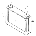
- FIG. 1 is a see-through perspective view showing one embodiment of a non-aqueous electrolyte storage element.
- FIG. 2 is a schematic diagram showing an embodiment of a power storage device configured by assembling a plurality of non-aqueous electrolyte power storage elements.
- a non-aqueous electrolyte storage element includes a positive electrode having a lithium-transition metal composite oxide containing manganese and a negative electrode having graphite.
- the manganese content is 20 mol % or less, and the charging depth of the graphite in a charged state is less than 0.54.
- the non-aqueous electrolyte storage element has a high capacity retention rate after charge-discharge cycles. Although the reason for this is not clear, the following reasons are presumed. In general, the decrease in the capacity retention rate of a non-aqueous electrolyte storage element with charge-discharge cycles is affected by the decrease in electronic conductivity due to cracks in the positive electrode active material. On the other hand, in the lithium transition metal composite oxide containing manganese, which is the positive electrode active material, the higher the manganese content, the lower the electron conductivity. Therefore, by using a manganese-containing lithium-transition metal composite oxide with a low manganese content, sufficient electron conduction is achieved even when the lithium-transition metal composite oxide cracks due to charge-discharge cycles.
- Graphite refers to a carbon material having an average lattice spacing (d 002 ) of the (002) plane determined by X-ray diffraction before charging/discharging or in a discharged state of 0.33 nm or more and less than 0.34 nm.
- the “discharged state” of the carbon material means a state in which the carbon material, which is the negative electrode active material, is discharged such that lithium ions that can be intercalated and deintercalated are sufficiently released during charging and discharging.
- the open circuit voltage is 0.7 V or higher.
- the “charge depth of graphite in a charged state” refers to the ratio of the amount of charged electricity per mass of graphite in a charged state to the theoretical capacity per mass of graphite.
- the “theoretical capacity” refers to the maximum amount of electricity that a unit mass of active material can store in an assumed electrochemical reaction, and in this specification, the theoretical capacity of graphite is 372 mAh/g.
- the “charged state” refers to a state in which the non-aqueous electrolyte storage element is charged up to the rated upper limit voltage for securing the rated capacity determined in advance by design.
- the non-aqueous electrolyte storage element when charging is performed using the charging control device adopted by the non-aqueous electrolyte storage element, charging is performed until it reaches the charging cut-off voltage when the charging operation is controlled to stop. It refers to the state of being For example, the non-aqueous electrolyte storage element is charged at a constant current of 1/3 C until the rated upper limit voltage or the charging end voltage is reached, and then the current is constant until the current reaches 0.01 C at the rated upper limit voltage or the charging end voltage.
- a state in which voltage charging is performed is a typical example of the “charged state” referred to here. Specifically, the "charged electricity amount per mass of graphite in a charged state" shall be measured by the following procedure.
- the above lithium-transition metal composite oxide preferably further contains nickel and cobalt. In such a case, the capacity retention rate after charge-discharge cycles is further increased.
- a non-aqueous electrolyte storage device, a storage device, a method for manufacturing a non-aqueous electrolyte storage device, and other embodiments according to one embodiment of the present invention will be described in detail. Note that the name of each component (each component) used in each embodiment may be different from the name of each component (each component) used in the background art.
- a non-aqueous electrolyte storage element includes an electrode body having a positive electrode, a negative electrode and a separator, a non-aqueous electrolyte, the electrode body and the non-aqueous electrolyte and a container that houses the
- the electrode body is usually a laminated type in which a plurality of positive electrodes and a plurality of negative electrodes are laminated with separators interposed therebetween, or a wound type in which positive electrodes and negative electrodes are laminated with separators interposed and wound.
- the non-aqueous electrolyte exists in a state contained in the positive electrode, the negative electrode and the separator.
- a non-aqueous electrolyte secondary battery hereinafter also simply referred to as "secondary battery" will be described.
- the positive electrode has a positive electrode base material and a positive electrode active material layer disposed directly on the positive electrode base material or via an intermediate layer.
- a positive electrode base material has electroconductivity. Whether or not a material has "conductivity" is determined using a volume resistivity of 10 ⁇ 2 ⁇ cm as a threshold measured according to JIS-H-0505 (1975).
- the material for the positive electrode substrate metals such as aluminum, titanium, tantalum and stainless steel, or alloys thereof are used. Among these, aluminum or an aluminum alloy is preferable from the viewpoint of potential resistance, high conductivity, and cost.
- the positive electrode substrate include foil, deposited film, mesh, porous material, and the like, and foil is preferable from the viewpoint of cost. Therefore, aluminum foil or aluminum alloy foil is preferable as the positive electrode substrate. Examples of aluminum or aluminum alloys include A1085, A3003, A1N30, etc. defined in JIS-H-4000 (2014) or JIS-H4160 (2006).
- the average thickness of the positive electrode substrate is preferably 3 ⁇ m or more and 50 ⁇ m or less, more preferably 5 ⁇ m or more and 40 ⁇ m or less, even more preferably 8 ⁇ m or more and 30 ⁇ m or less, and particularly preferably 10 ⁇ m or more and 25 ⁇ m or less.
- the intermediate layer is a layer arranged between the positive electrode substrate and the positive electrode active material layer.
- the intermediate layer contains a conductive agent such as carbon particles to reduce the contact resistance between the positive electrode substrate and the positive electrode active material layer.
- the composition of the intermediate layer is not particularly limited, and includes, for example, a binder and a conductive agent.
- the positive electrode active material layer contains a positive electrode active material.
- the positive electrode active material layer contains arbitrary components such as a conductive agent, a binder (binding agent), a thickener, a filler, etc., as required.
- the positive electrode active material contains a lithium transition metal composite oxide containing manganese.
- the lithium-transition metal composite oxide preferably further contains at least one of nickel and cobalt, more preferably both nickel and cobalt.
- the upper limit of the ratio of manganese to the metal elements other than lithium in the lithium-transition metal composite oxide is 20 mol%, may be 19 mol%, is preferably 18 mol%, and more preferably 17 mol%. Mole % is more preferred, and 15 mole % is even more preferred in some cases.
- the ratio of manganese is equal to or less than the above upper limit, the electronic conductivity of the lithium-transition metal composite oxide can be enhanced, and the capacity retention rate of the non-aqueous electrolyte storage device after charge-discharge cycles can be enhanced.
- the lower limit of the ratio of manganese is preferably 1 mol%, may be 2 mol%, 3 mol%, 4 mol%, more preferably 5 mol%, 6 mol%, 7 mol%, 8 mol%, 9 mol%. In some cases, mol % is more preferred, 10 mol % is more preferred, and 11 mol %, 12 mol %, 13 mol %, 14 mol %, 15 mol % are even more preferred in some cases.
- cost reduction can be achieved.
- the ratio of manganese can be within a range of combinations of any of the above upper limits and any of the above lower limits.
- the ratio of nickel to the metal elements other than lithium in the lithium-transition metal composite oxide is preferably 20 mol% or more and 80 mol% or less, may be 25 mol% or more and 75 mol% or less, or 30 mol% or more and 70 mol% or less. is more preferable, 35 mol% or more and 68 mol% or less is more preferable in some cases, 40 mol% or more and 65 mol% or less is more preferable, 45 mol% or more and 60 mol% or less is still more preferable, and 47 mol% or more and 55 mol% % or less is more preferable in some cases.
- the ratio of cobalt to the metal elements other than lithium in the lithium-transition metal composite oxide may be 1 mol% or more and 60 mol% or less, preferably 5 mol% or more and 60 mol% or less, and 10 mol% or more and 50 mol% or less. is more preferable, sometimes 15 mol% or more and 48 mol% or less is more preferable, 20 mol% or more and 45 mol% or less is even more preferable, and 25 mol% or more and 43 mol% or less is even more preferable. More than 40 mol % or less is even more preferable.
- the ratio of cobalt within the above range, the capacity retention rate after charge-discharge cycles can be further increased. Further, by setting the ratio of cobalt to the above upper limit or less, cost reduction can be achieved.
- the lithium-transition metal composite oxide may further contain metal elements other than lithium, manganese, nickel and cobalt, such as aluminum.
- the ratio of the total amount of manganese, nickel and cobalt to the metal elements other than lithium in the lithium-transition metal composite oxide is preferably 90 mol% or more, more preferably 99 mol% or more, and substantially 100 mol%. It is more preferable to have
- lithium-transition metal composite oxide a lithium-transition metal composite oxide having a layered ⁇ -NaFeO 2 type crystal structure is preferred. Moreover, as the lithium-transition metal composite oxide, a compound represented by the following formula 1 is preferable.
- Me is two or more metal elements containing Mn at a ratio of 20 mol % or less. 0 ⁇ 1.
- ⁇ in Formula 1 may be 0 or more and 0.5 or less, 0 or more and 0.3 or less, or 0 or more and 0.1 or less.
- Me preferably further contains at least one of Ni and Co, more preferably both Ni and Co.
- the preferred ratios of the respective and total amounts of Mn, Ni and Co in Me are the preferred ratios of the respective and total amounts of manganese, nickel and cobalt in the metal elements other than lithium in the lithium-transition metal composite oxide. A ratio can be employed.
- Me may further contain metal elements other than Mn, Ni and Co.
- the surface of the lithium-transition metal composite oxide may be coated with another material.
- Other materials for coating the surface include compounds containing aluminum, tungsten, boron, etc. Compounds containing boron are preferred. Compounds containing aluminum, tungsten, boron and the like include oxides thereof.
- the content of the lithium-transition metal composite oxide containing manganese and having a ratio of manganese to the metal elements excluding lithium of 20 mol% or less is preferably 50% by mass or more and 99% by mass or less, and 70% by mass or less. It is more preferably from 80% by mass to 95% by mass, and even more preferably from 80% by mass to 95% by mass.
- the positive electrode active material may further contain a positive electrode active material other than the lithium-transition metal composite oxide.
- a positive electrode active material conventionally known various positive electrode active materials can be used.
- the content of the lithium-transition metal composite oxide in all positive electrode active materials contained in the positive electrode active material layer is preferably 90% by mass or more, more preferably 99% by mass or more.
- the electron conductivity is sufficiently increased.
- the capacity retention rate after charge-discharge cycles can be further increased.
- the content of all positive electrode active materials in the positive electrode active material layer is preferably 50% by mass or more and 99% by mass or less, more preferably 70% by mass or more and 98% by mass or less, and even more preferably 80% by mass or more and 95% by mass or less.
- the positive electrode active material is usually particles (powder).
- the average particle size of the positive electrode active material is preferably, for example, 0.1 ⁇ m or more and 20 ⁇ m or less. By making the average particle size of the positive electrode active material equal to or more than the above lower limit, manufacturing or handling of the positive electrode active material becomes easy. By setting the average particle size of the positive electrode active material to the above upper limit or less, the electron conductivity of the positive electrode active material layer is improved. Note that when a composite of a positive electrode active material and another material is used, the average particle size of the composite is taken as the average particle size of the positive electrode active material.
- Average particle size is based on JIS-Z-8825 (2013), based on the particle size distribution measured by a laser diffraction / scattering method for a diluted solution in which particles are diluted with a solvent, JIS-Z-8819 -2 (2001) means a value at which the volume-based integrated distribution calculated according to 50%.
- Pulverizers, classifiers, etc. are used to obtain powder with a predetermined particle size.
- Pulverization methods include, for example, methods using a mortar, ball mill, sand mill, vibrating ball mill, planetary ball mill, jet mill, counter jet mill, whirling jet mill, or sieve.
- wet pulverization in which water or an organic solvent such as hexane is allowed to coexist can also be used.
- a sieve, an air classifier, or the like is used as necessary, both dry and wet.
- the conductive agent is not particularly limited as long as it is a conductive material.
- Examples of such conductive agents include carbonaceous materials, metals, and conductive ceramics.
- Carbonaceous materials include graphite, non-graphitic carbon, graphene-based carbon, and the like.
- Examples of non-graphitic carbon include carbon nanofiber, pitch-based carbon fiber, and carbon black.
- Examples of carbon black include furnace black, acetylene black, and ketjen black.
- Graphene-based carbon includes graphene, carbon nanotube (CNT), fullerene, and the like.
- the shape of the conductive agent may be powdery, fibrous, or the like.
- As the conductive agent one type of these materials may be used alone, or two or more types may be mixed and used. Also, these materials may be combined for use.
- a composite material of carbon black and CNT may be used.
- carbon black is preferable from the viewpoint of electron conductivity and coatability
- acetylene black is particularly preferable
- the content of the conductive agent in the positive electrode active material layer is preferably 1% by mass or more and 10% by mass or less, more preferably 3% by mass or more and 9% by mass or less.
- Binders include, for example, fluorine resins (polytetrafluoroethylene (PTFE), polyvinylidene fluoride (PVDF), etc.), thermoplastic resins such as polyethylene, polypropylene, polyacryl, and polyimide; ethylene-propylene-diene rubber (EPDM), sulfone Elastomers such as modified EPDM, styrene-butadiene rubber (SBR) and fluororubber; polysaccharide polymers and the like.
- fluorine resins polytetrafluoroethylene (PTFE), polyvinylidene fluoride (PVDF), etc.
- thermoplastic resins such as polyethylene, polypropylene, polyacryl, and polyimide
- EPDM ethylene-propylene-diene rubber
- SBR styrene-butadiene rubber
- fluororubber polysaccharide polymers and the like.
- the content of the binder in the positive electrode active material layer is preferably 1% by mass or more and 10% by mass or less, more preferably 2% by mass or more and 9% by mass or less.
- thickeners examples include polysaccharide polymers such as carboxymethylcellulose (CMC) and methylcellulose.
- CMC carboxymethylcellulose
- methylcellulose examples include polysaccharide polymers such as carboxymethylcellulose (CMC) and methylcellulose.
- the functional group may be previously deactivated by methylation or the like.
- the filler is not particularly limited.
- Fillers include polyolefins such as polypropylene and polyethylene, inorganic oxides such as silicon dioxide, alumina, titanium dioxide, calcium oxide, strontium oxide, barium oxide, magnesium oxide and aluminosilicate, magnesium hydroxide, calcium hydroxide, hydroxide Hydroxides such as aluminum, carbonates such as calcium carbonate, sparingly soluble ionic crystals such as calcium fluoride, barium fluoride, and barium sulfate, nitrides such as aluminum nitride and silicon nitride, talc, montmorillonite, boehmite, zeolite, Mineral resource-derived substances such as apatite, kaolin, mullite, spinel, olivine, sericite, bentonite, and mica, or artificial products thereof may be used.
- the positive electrode active material layer contains typical nonmetallic elements such as B, N, P, F, Cl, Br, and I, Li, Na, Mg, Al, K, Ca, Zn, Ga, Ge, Sn, Sr, Ba, and the like.
- typical metal elements, transition metal elements such as Sc, Ti, V, Cr, Mn, Fe, Co, Ni, Cu, Mo, Zr, Nb, W are used as positive electrode active materials, conductive agents, binders, thickeners, fillers It may be contained as a component other than
- the negative electrode has a negative electrode base material and a negative electrode active material layer disposed directly on the negative electrode base material or via an intermediate layer.
- the structure of the intermediate layer is not particularly limited, and can be selected from, for example, the structures exemplified for the positive electrode.
- the negative electrode base material has conductivity.
- materials for the negative electrode substrate metals such as copper, nickel, stainless steel, nickel-plated steel, alloys thereof, carbonaceous materials, and the like are used. Among these, copper or a copper alloy is preferred.
- the negative electrode substrate include foil, deposited film, mesh, porous material, and the like, and foil is preferable from the viewpoint of cost. Therefore, copper foil or copper alloy foil is preferable as the negative electrode substrate.
- Examples of copper foil include rolled copper foil and electrolytic copper foil.
- the average thickness of the negative electrode substrate is preferably 2 ⁇ m or more and 35 ⁇ m or less, more preferably 3 ⁇ m or more and 30 ⁇ m or less, even more preferably 4 ⁇ m or more and 25 ⁇ m or less, and particularly preferably 5 ⁇ m or more and 20 ⁇ m or less.
- the negative electrode active material layer contains a negative electrode active material.
- the negative electrode active material layer contains arbitrary components such as a conductive agent, a binder, a thickener, a filler, etc., as required.
- Optional components such as conductive agents, binders, thickeners, and fillers can be selected from the materials exemplified for the positive electrode.
- the negative electrode active material layer contains typical nonmetallic elements such as B, N, P, F, Cl, Br, and I, Li, Na, Mg, Al, K, Ca, Zn, Ga, Ge, Sn, Sr, Ba, and the like. and transition metal elements such as Sc, Ti, V, Cr, Mn, Fe, Co, Ni, Cu, Mo, Zr, Ta, Hf, Nb, and W are used as negative electrode active materials, conductive agents, binders, and thickeners. You may contain as a component other than a sticky agent and a filler.
- the negative electrode active material contains graphite. By including graphite in the negative electrode active material, the capacity retention rate after charge-discharge cycles can be increased. In addition, since the negative electrode active material contains graphite, it is possible to design the charging depth with high accuracy.
- Graphite includes natural graphite and artificial graphite. Artificial graphite is preferable from the viewpoint that a material with stable physical properties can be obtained.
- the charge depth of graphite, which is the negative electrode active material, in a charged state is less than 0.54, preferably 0.53 or less, and more preferably 0.52 or less.
- the charge depth of the graphite is preferably 0.40 or more, may be 0.41 or more, more preferably 0.42 or more, and may be 0.43 or more, 0.44 or more, and 0.45.
- 0.46 or more and 0.47 or more are more preferable, 0.48 or more and 0.49 or more are still more preferable, and 0.50 or more is especially preferable.
- the charge depth of the graphite When the charge depth of the graphite is equal to or higher than the lower limit, the energy density of the non-aqueous electrolyte storage element can be increased.
- the charge depth of the graphite can be within a range of combinations of any of the above upper limits and any of the above lower limits.
- the charge depth of graphite which is the negative electrode active material in the charged state, can be obtained, for example, by changing the ratio of the mass of graphite per unit area in the negative electrode active material layer to the mass of the positive electrode active material per unit area in the positive electrode active material layer. can be adjusted.
- the content of graphite in the negative electrode active material layer is preferably 60% by mass or more and 99% by mass or less, more preferably 90% by mass or more and 98% by mass or less, and even more preferably 95% by mass or more in some cases.
- the negative electrode active material may contain other negative electrode active materials other than graphite.
- As other negative electrode active materials conventionally known various negative electrode active materials can be used.
- the content of graphite in all negative electrode active materials contained in the negative electrode active material layer is preferably 90% by mass or more, more preferably 99% by mass or more, and may be substantially 100% by mass.
- the capacity retention rate after charge-discharge cycles can be further increased.
- the charging depth of graphite in the charged state can be designed with high accuracy.
- the content of all negative electrode active materials in the negative electrode active material layer is preferably 60% by mass or more and 99% by mass or less, more preferably 90% by mass or more and 98% by mass or less.
- Graphite and other negative electrode active materials are usually particles (powder).
- the average particle size of the negative electrode active material can be, for example, 1 nm or more and 100 ⁇ m or less.
- the average particle size may be 1 ⁇ m or more and 100 ⁇ m or less.
- a pulverizer, a classifier, or the like is used to obtain powder having a predetermined particle size.
- the pulverization method and the powder class method can be selected from, for example, the methods exemplified for the positive electrode.
- the porosity of the negative electrode active material layer is preferably 30% or more and 60% or less, more preferably 40% or more and 50% or less. When the porosity of the negative electrode active material layer is within the above range, the charge/discharge performance can be enhanced.
- the porosity of the negative electrode active material layer can be adjusted by the strength of pressing when forming the negative electrode active material layer, the material constituting the negative electrode active material layer, and the like.
- the “porosity” of the negative electrode active material layer is a volume-based value and is a value measured with a mercury porosimeter.
- the negative electrode that has been completely discharged by the procedure for measuring the "charged electricity amount per mass of graphite in a charged state" is taken out, and the step of immersing it in dimethyl carbonate for 5 minutes is repeated twice.
- the non-aqueous electrolyte adhering to the electrode is thoroughly washed, and the washed negative electrode is dried under reduced pressure at room temperature for a whole day and night before measurement.
- the separator can be appropriately selected from known separators.
- a separator consisting of only a substrate layer, a separator having a heat-resistant layer containing heat-resistant particles and a binder formed on one or both surfaces of a substrate layer, or the like can be used.
- Examples of the shape of the base layer of the separator include woven fabric, nonwoven fabric, and porous resin film. Among these shapes, a porous resin film is preferred from the viewpoint of strength, and a non-woven fabric is preferred from the viewpoint of non-aqueous electrolyte retention.
- polyolefins such as polyethylene and polypropylene are preferable from the viewpoint of shutdown function, and polyimide, aramid, and the like are preferable from the viewpoint of oxidative decomposition resistance.
- a material obtained by combining these resins may be used as the base material layer of the separator.
- the heat-resistant particles contained in the heat-resistant layer preferably have a mass loss of 5% or less when the temperature is raised from room temperature to 500 ° C. in an air atmosphere of 1 atm, and the mass loss when the temperature is raised from room temperature to 800 ° C. is more preferably 5% or less.
- An inorganic compound can be mentioned as a material whose mass reduction is less than or equal to a predetermined value. Examples of inorganic compounds include oxides such as iron oxide, silicon oxide, aluminum oxide, titanium oxide, zirconium oxide, calcium oxide, strontium oxide, barium oxide, magnesium oxide, and aluminosilicate; nitrides such as aluminum nitride and silicon nitride.
- carbonates such as calcium carbonate
- sulfates such as barium sulfate
- sparingly soluble ionic crystals such as calcium fluoride, barium fluoride, and barium titanate
- covalent crystals such as silicon and diamond
- Mineral resource-derived substances such as zeolite, apatite, kaolin, mullite, spinel, olivine, sericite, bentonite, and mica, or artificial products thereof.
- the inorganic compound a single substance or a composite of these substances may be used alone, or two or more of them may be mixed and used.
- silicon oxide, aluminum oxide, or aluminosilicate is preferable from the viewpoint of the safety of the electric storage device.
- the porosity of the separator is preferably 80% by volume or less from the viewpoint of strength, and preferably 20% by volume or more from the viewpoint of discharge performance.
- the "porosity” is a volume-based value and means a value measured with a mercury porosimeter.
- a polymer gel composed of a polymer and a non-aqueous electrolyte may be used as the separator.
- examples of polymers include polyacrylonitrile, polyethylene oxide, polypropylene oxide, polymethyl methacrylate, polyvinyl acetate, polyvinylpyrrolidone, polyvinylidene fluoride, and the like.
- the use of polymer gel has the effect of suppressing liquid leakage.
- a polymer gel may be used in combination with the porous resin film or non-woven fabric as described above.
- Non-aqueous electrolyte The non-aqueous electrolyte can be appropriately selected from known non-aqueous electrolytes. A non-aqueous electrolyte may be used as the non-aqueous electrolyte.
- the non-aqueous electrolyte contains a non-aqueous solvent and an electrolyte salt dissolved in this non-aqueous solvent.
- the non-aqueous solvent can be appropriately selected from known non-aqueous solvents.
- Non-aqueous solvents include cyclic carbonates, chain carbonates, carboxylic acid esters, phosphoric acid esters, sulfonic acid esters, ethers, amides, nitriles and the like.
- the non-aqueous solvent those in which some of the hydrogen atoms contained in these compounds are substituted with halogens may be used.
- Cyclic carbonates include ethylene carbonate (EC), propylene carbonate (PC), butylene carbonate (BC), vinylene carbonate (VC), vinylethylene carbonate (VEC), chloroethylene carbonate, fluoroethylene carbonate (FEC), and difluoroethylene carbonate. (DFEC), styrene carbonate, 1-phenylvinylene carbonate, 1,2-diphenylvinylene carbonate and the like. Among these, EC is preferred.
- chain carbonates examples include diethyl carbonate (DEC), dimethyl carbonate (DMC), ethylmethyl carbonate (EMC), diphenyl carbonate, trifluoroethylmethyl carbonate, bis(trifluoroethyl) carbonate, and the like. Among these, EMC is preferred.
- the non-aqueous solvent it is preferable to use a cyclic carbonate or a chain carbonate, and it is more preferable to use a combination of a cyclic carbonate and a chain carbonate.
- a cyclic carbonate it is possible to promote the dissociation of the electrolyte salt and improve the ionic conductivity of the non-aqueous electrolyte.
- a chain carbonate By using a chain carbonate, the viscosity of the non-aqueous electrolyte can be kept low.
- the volume ratio of the cyclic carbonate to the chain carbonate is preferably in the range of, for example, 5:95 to 50:50.
- Lithium salts include inorganic lithium salts such as LiPF 6 , LiPO 2 F 2 , LiBF 4 , LiClO 4 and LiN(SO 2 F) 2 , lithium bis(oxalate) borate (LiBOB), lithium difluorooxalate borate (LiFOB).
- lithium oxalate salts such as lithium bis ( oxalate) difluorophosphate (LiFOP), LiSO3CF3 , LiN( SO2CF3 ) 2 , LiN ( SO2C2F5 ) 2 , LiN( SO2CF3 ) (SO 2 C 4 F 9 ), LiC(SO 2 CF 3 ) 3 , LiC(SO 2 C 2 F 5 ) 3 and other lithium salts having a halogenated hydrocarbon group.
- inorganic lithium salts are preferred, and LiPF6 is more preferred.
- the content of the electrolyte salt in the non-aqueous electrolyte is preferably 0.1 mol/dm3 or more and 2.5 mol/dm3 or less, and 0.3 mol/ dm3 or more and 2.0 mol/dm3 or less at 20°C and 1 atm. It is more preferably 3 or less, more preferably 0.5 mol/dm 3 or more and 1.7 mol/dm 3 or less, and particularly preferably 0.7 mol/dm 3 or more and 1.5 mol/dm 3 or less.
- the non-aqueous electrolyte may contain additives in addition to the non-aqueous solvent and electrolyte salt.
- additives include aromatic compounds such as biphenyl, alkylbiphenyl, terphenyl, partially hydrogenated terphenyl, cyclohexylbenzene, t-butylbenzene, t-amylbenzene, diphenyl ether, and dibenzofuran; 2-fluorobiphenyl, Partial halides of the above aromatic compounds such as o-cyclohexylfluorobenzene and p-cyclohexylfluorobenzene; 2,4-difluoroanisole, 2,5-difluoroanisole, 2,6-difluoroanisole, 3,5-difluoroanisole, etc.
- the content of the additive contained in the non-aqueous electrolyte is preferably 0.01% by mass or more and 10% by mass or less, and 0.1% by mass or more and 7% by mass or less with respect to the total mass of the non-aqueous electrolyte. More preferably, it is 0.2% by mass or more and 5% by mass or less, and particularly preferably 0.3% by mass or more and 3% by mass or less.
- a solid electrolyte may be used as the non-aqueous electrolyte, or a non-aqueous electrolyte and a solid electrolyte may be used together.
- the solid electrolyte can be selected from any material that has lithium ion conductivity and is solid at room temperature (for example, 15° C. to 25° C.).
- Examples of solid electrolytes include sulfide solid electrolytes, oxide solid electrolytes, oxynitride solid electrolytes, polymer solid electrolytes, and the like.
- Examples of sulfide solid electrolytes include Li 2 SP 2 S 5 , LiI—Li 2 SP 2 S 5 , Li 10 Ge—P 2 S 12 and the like.
- the shape of the non-aqueous electrolyte storage element of the present embodiment is not particularly limited, and examples thereof include cylindrical batteries, square batteries, flat batteries, coin batteries, button batteries, and the like.
- Fig. 1 shows a non-aqueous electrolyte storage element 1 as an example of a square battery.
- An electrode body 2 having a positive electrode and a negative electrode wound with a separator sandwiched therebetween is housed in a rectangular container 3 .
- the positive electrode is electrically connected to the positive electrode terminal 4 via a positive electrode lead 41 .
- the negative electrode is electrically connected to the negative terminal 5 via a negative lead 51 .
- the non-aqueous electrolyte storage element of the present embodiment is a power source for automobiles such as electric vehicles (EV), hybrid vehicles (HEV), and plug-in hybrid vehicles (PHEV), power sources for electronic devices such as personal computers and communication terminals, or electric power It can be installed in a power source for storage or the like as a power storage unit (battery module) configured by collecting a plurality of non-aqueous electrolyte power storage elements 1 .
- the technology of the present invention may be applied to at least one non-aqueous electrolyte storage element included in the storage unit.
- a power storage device includes one or more nonaqueous electrolyte power storage elements according to one embodiment of the present invention.
- FIG. 2 shows an example of a power storage device 30 in which a power storage unit 20 in which two or more electrically connected non-aqueous electrolyte power storage elements 1 are assembled is further assembled.
- the power storage device 30 includes a bus bar (not shown) electrically connecting two or more non-aqueous electrolyte power storage elements 1, a bus bar (not shown) electrically connecting two or more power storage units 20, and the like. good too.
- the power storage unit 20 or the power storage device 30 may include a state monitoring device (not shown) that monitors the state of one or more non-aqueous electrolyte power storage elements.
- a method for manufacturing the non-aqueous electrolyte storage element of the present embodiment can be appropriately selected from known methods.
- the manufacturing method includes, for example, preparing an electrode body, preparing a non-aqueous electrolyte, and housing the electrode body and the non-aqueous electrolyte in a container.
- Preparing the electrode body includes preparing a positive electrode and a negative electrode, and forming the electrode body by laminating or winding the positive electrode and the negative electrode with a separator interposed therebetween.
- Containing the non-aqueous electrolyte in the container can be appropriately selected from known methods.
- the non-aqueous electrolyte may be injected through an inlet formed in the container, and then the inlet may be sealed.
- non-aqueous electrolyte storage device of the present invention is not limited to the above embodiments, and various modifications may be made without departing from the gist of the present invention.
- the configuration of another embodiment can be added to the configuration of one embodiment, and part of the configuration of one embodiment can be replaced with the configuration of another embodiment or a known technique.
- some of the configurations of certain embodiments can be deleted.
- well-known techniques can be added to the configuration of a certain embodiment.
- the nonaqueous electrolyte storage element is used as a chargeable/dischargeable nonaqueous electrolyte secondary battery (lithium ion secondary battery). etc. are optional.
- the present invention can also be applied to capacitors such as various secondary batteries, electric double layer capacitors, and lithium ion capacitors.
- the electrode body in which the positive electrode and the negative electrode are laminated with a separator interposed therebetween has been described, but the electrode body does not have to have a separator.
- the positive electrode and the negative electrode may be in direct contact with each other in a state in which a layer having no conductivity is formed on the active material layer of the positive electrode or the negative electrode.
- Example 1 (Preparation of positive electrode) LiNi 0.45 Co 0.35 Mn 0.20 O 2 as a positive electrode active material, acetylene black (AB) as a conductive agent, polyvinylidene fluoride (PVDF) as a binder, and N-methylpyrrolidone (NMP) as a dispersion medium. ) was used to prepare a positive electrode mixture paste.
- the mass ratio of the positive electrode active material, AB and PVDF was 93:3.5:3.5 (in terms of solid content).
- a positive electrode material mixture paste was applied to both surfaces of an aluminum foil serving as a positive electrode substrate and dried. After that, roll pressing was performed to obtain a positive electrode.
- a negative electrode mixture paste was prepared using graphite as a negative electrode active material, styrene-butadiene rubber (SBR) as a binder, carboxymethyl cellulose (CMC) as a thickener, and water as a dispersion medium.
- SBR styrene-butadiene rubber
- CMC carboxymethyl cellulose
- a negative electrode mixture paste was applied to both sides of a copper foil as a negative electrode base material and dried. After that, roll pressing was performed to obtain a negative electrode.
- the ratio of the mass of graphite per unit area in the negative electrode active material layer to the mass of the positive electrode active material per unit area in the positive electrode active material layer was adjusted so that the charge depth of graphite in the charged state was 0.52. .
- Non-aqueous electrolyte LiPF 6 was dissolved at a concentration of 1.2 mol/dm 3 in a solvent in which ethylene carbonate and ethyl methyl carbonate were mixed at a volume ratio of 30:70 to obtain a non-aqueous electrolyte.
- a wound electrode body was obtained using the positive electrode, the negative electrode, and the separator.
- the electrode body was placed in a container, a non-aqueous electrolyte was injected, and the container was sealed to obtain a non-aqueous electrolyte storage element (secondary battery) of Example 1.
- Examples 2 to 3 and Comparative Examples 1 to 6 The positive electrode active material shown in Table 1 is used, and the negative electrode active material with respect to the mass of the positive electrode active material per unit area in the positive electrode active material layer so that the charge depth of graphite in the charged state becomes the value shown in Table 1
- Non-aqueous electrolyte storage elements of Examples 2 to 3 and Comparative Examples 1 to 6 were obtained in the same manner as in Example 1, except that the ratio of graphite mass per unit area in the layer was adjusted.
- constant current charging was performed with a charging current of 4.0 C to an amount of electricity equivalent to 85% of the initial discharge capacity, thereby adjusting the SOC of the non-aqueous electrolyte storage element to 85%.
- constant current discharge was carried out at a discharge current of 4.0 C to an amount of electricity equivalent to 70% of the initial discharge capacity, thereby adjusting the SOC of the non-aqueous electrolyte storage element to 15%.
- constant current charging was performed at 4.0 C to an amount of electricity equivalent to 70% of the initial discharge capacity, and the non-aqueous electrolyte storage element was adjusted to SOC 85%.
- the positive electrode active material is a lithium-transition metal composite oxide in which the ratio of manganese to the metal elements excluding lithium is 20 mol% or less, and the negative electrode active material is graphite.
- the capacity retention rate after 2000 hours of charge/discharge cycles exceeded 80%.
- the non-aqueous electrolyte storage element includes a positive electrode having a lithium-transition metal composite oxide containing manganese and a negative electrode having graphite. It was shown that the capacity retention rate after charge-discharge cycles is high when the proportion of manganese is 20 mol % or less and the charge depth of the graphite in the charged state is less than 0.54.
- the present invention can be applied to electronic devices such as personal computers, communication terminals, non-aqueous electrolyte storage elements and storage devices used as power sources for automobiles and the like.
- Non-aqueous electrolyte storage element 1 Non-aqueous electrolyte storage element 2 Electrode body 3 Container 4 Positive electrode terminal 41 Positive electrode lead 5 Negative electrode terminal 51 Negative electrode lead 20 Storage unit 30 Storage device
Landscapes
- Chemical & Material Sciences (AREA)
- Engineering & Computer Science (AREA)
- Chemical Kinetics & Catalysis (AREA)
- Electrochemistry (AREA)
- General Chemical & Material Sciences (AREA)
- Power Engineering (AREA)
- Materials Engineering (AREA)
- Microelectronics & Electronic Packaging (AREA)
- Inorganic Chemistry (AREA)
- Manufacturing & Machinery (AREA)
- Secondary Cells (AREA)
Abstract
Description
具体的に「充電状態における黒鉛の質量あたりの充電電気量」は、以下の手順で測定するものとする。
(1)対象となる非水電解質蓄電素子を定格容量が得られたときの下限電圧(SOC0%)まで放電した後に、酸素濃度5ppm以下のアルゴン雰囲気に制御したグローブボックス内で解体する。
(2)上記グローブボックス内で、正極及び負極を取り出して小型パウチセル(I)を組み立てる。
(3)小型パウチセル(I)を充電して上記充電状態とした後、非水電解質蓄電素子で定格容量が得られたときの下限電圧まで0.01Cの電流にて定電流放電を行う。
(4)酸素濃度5ppm以下のアルゴン雰囲気に制御したグローブボックス内で、小型パウチセル(I)を解体し、負極を取り出して対極としてリチウム金属を配置した小型パウチセル(II)を組み立てる。
(5)小型パウチセル(II)を電圧が2.0Vとなるまで、0.01Cの電流で追加放電を行い、負極を完全放電状態に調整する。
(6)上記(3)及び(5)における放電電気量の合計を小型パウチセル(I)における正負極対向部の負極活物質層における黒鉛の質量で割り算して、充電状態における黒鉛の質量あたりの充電電気量とする。
なお、ここでは負極活物質にリチウムイオン等が吸蔵される還元反応を「充電」、負極活物質からリチウムイオン等が放出される酸化反応を「放電」という。
本発明の一実施形態に係る非水電解質蓄電素子(以下、単に「蓄電素子」ともいう。)は、正極、負極及びセパレータを有する電極体と、非水電解質と、上記電極体及び非水電解質を収容する容器と、を備える。電極体は、通常、複数の正極及び複数の負極がセパレータを介して積層された積層型、又は、正極及び負極がセパレータを介して積層された状態で巻回された巻回型である。非水電解質は、正極、負極及びセパレータに含まれた状態で存在する。非水電解質蓄電素子の一例として、非水電解質二次電池(以下、単に「二次電池」ともいう。)について説明する。
正極は、正極基材と、当該正極基材に直接又は中間層を介して配される正極活物質層とを有する。
式1中、MeはMnを20モル%以下の比率で含む2種以上の金属元素である。0≦α<1である。
負極は、負極基材と、当該負極基材に直接又は中間層を介して配される負極活物質層とを有する。中間層の構成は特に限定されず、例えば上記正極で例示した構成から選択することができる。
セパレータは、公知のセパレータの中から適宜選択できる。セパレータとして、例えば、基材層のみからなるセパレータ、基材層の一方の面又は双方の面に耐熱粒子とバインダとを含む耐熱層が形成されたセパレータ等を使用することができる。セパレータの基材層の形状としては、例えば、織布、不織布、多孔質樹脂フィルム等が挙げられる。これらの形状の中でも、強度の観点から多孔質樹脂フィルムが好ましく、非水電解質の保液性の観点から不織布が好ましい。セパレータの基材層の材料としては、シャットダウン機能の観点から例えばポリエチレン、ポリプロピレン等のポリオレフィンが好ましく、耐酸化分解性の観点から例えばポリイミドやアラミド等が好ましい。セパレータの基材層として、これらの樹脂を複合した材料を用いてもよい。
非水電解質としては、公知の非水電解質の中から適宜選択できる。非水電解質には、非水電解液を用いてもよい。非水電解液は、非水溶媒と、この非水溶媒に溶解されている電解質塩とを含む。
本実施形態の非水電解質蓄電素子は、電気自動車(EV)、ハイブリッド自動車(HEV)、プラグインハイブリッド自動車(PHEV)等の自動車用電源、パーソナルコンピュータ、通信端末等の電子機器用電源、又は電力貯蔵用電源等に、複数の非水電解質蓄電素子1を集合して構成した蓄電ユニット(バッテリーモジュール)として搭載することができる。この場合、蓄電ユニットに含まれる少なくとも一つの非水電解質蓄電素子に対して、本発明の技術が適用されていればよい。
本実施形態の非水電解質蓄電素子の製造方法は、公知の方法から適宜選択できる。当該製造方法は、例えば、電極体を準備することと、非水電解質を準備することと、電極体及び非水電解質を容器に収容することと、を備える。電極体を準備することは、正極及び負極を準備することと、セパレータを介して正極及び負極を積層又は巻回することにより電極体を形成することとを備える。
尚、本発明の非水電解質蓄電素子は、上記実施形態に限定されるものではなく、本発明の要旨を逸脱しない範囲内において種々変更を加えてもよい。例えば、ある実施形態の構成に他の実施形態の構成を追加することができ、また、ある実施形態の構成の一部を他の実施形態の構成又は周知技術に置き換えることができる。さらに、ある実施形態の構成の一部を削除することができる。また、ある実施形態の構成に対して周知技術を付加することができる。
(正極の作製)
正極活物質であるLiNi0.45Co0.35Mn0.20O2、導電剤であるアセチレンブラック(AB)、バインダであるポリフッ化ビニリデン(PVDF)及び分散媒であるN-メチルピロリドン(NMP)を用いて正極合剤ペーストを調製した。なお、正極活物質、AB及びPVDFの質量比率は93:3.5:3.5(固形分換算)とした。正極基材としてのアルミニウム箔の両面に正極合剤ペーストを塗布し、乾燥した。その後、ロールプレスを行い、正極を得た。
負極活物質である黒鉛、バインダであるスチレン-ブタジエンゴム(SBR)、増粘剤であるカルボキシメチルセルロース(CMC)、及び分散媒である水を用いて負極合剤ペーストを調製した。なお、黒鉛、SBR及びCMCの質量比率は97.5:1.5:1(固形分換算)とした。負極基材としての銅箔の両面に負極合剤ペーストを塗布し、乾燥した。その後、ロールプレスを行い、負極を得た。
なお、充電状態における黒鉛の充電深度が0.52となるように、正極活物質層における単位面積あたりの正極活物質の質量に対する負極活物質層における単位面積あたりの黒鉛の質量の比を調整した。
エチレンカーボネート及びエチルメチルカーボネートを30:70の体積比率で混合した溶媒に、1.2mol/dm3の濃度でLiPF6を溶解させ、非水電解液を得た。
セパレータには、ポリオレフィン製微多孔膜を用いた。
上記正極と負極とセパレータとを用いて巻回型の電極体を得た。電極体を容器に収納し、非水電解液を注入して封口し、実施例1の非水電解質蓄電素子(二次電池)を得た。
表1に記載の正極活物質を用いたこと、及び充電状態における黒鉛の充電深度が表1に記載の値となるように正極活物質層における単位面積あたりの正極活物質の質量に対する負極活物質層における単位面積あたりの黒鉛の質量の比を調整したこと以外は実施例1と同様にして、実施例2から3及び比較例1から6の各非水電解質蓄電素子を得た。
(1)初期放電容量確認試験
得られた各非水電解質蓄電素子について、以下の条件にて初期放電容量確認試験を行った。25℃の恒温槽内において、充電電流1.0C、充電終止電圧4.10Vとして定電流充電を行った後、4.10Vにて定電圧充電した。充電の終了条件は、総充電時間が3時間となるまでとした。その後、10分間の休止期間を設けた。放電電流1.0C、放電終止電圧2.50Vとして定電流放電した。これにより、初期放電容量を測定した。
(2)充放電サイクル2000時間後の容量維持率
次いで、以下の充放電サイクル試験を行った。60℃の恒温槽内において、充電電流4.0Cで、初期放電容量の85%の電気量を定電流充電し、非水電解質蓄電素子をSOC85%に調整した。その後、休止期間を設けずに、放電電流4.0Cで、初期放電容量の70%の電気量を定電流放電し、非水電解質蓄電素子をSOC15%に調整した。続いて、4.0Cで、初期放電容量の70%の電気量を定電流充電し、非水電解質蓄電素子をSOC85%に調整した。その後、休止期間を設けずに、放電電流4.0Cで、初期放電容量の70%の電気量を定電流放電し、非水電解質蓄電素子をSOC15%に調整した。この充放電を2000時間実施した。その後上記(1)と同様の方法で放電容量確認試験を行った。これにより、充放電サイクル2000時間後の放電容量を測定した。初期放電容量に対する充放電サイクル2000時間後の放電容量の百分率を算出し、充放電サイクル2000時間後の容量維持率(%)とした。結果を表1に示す。
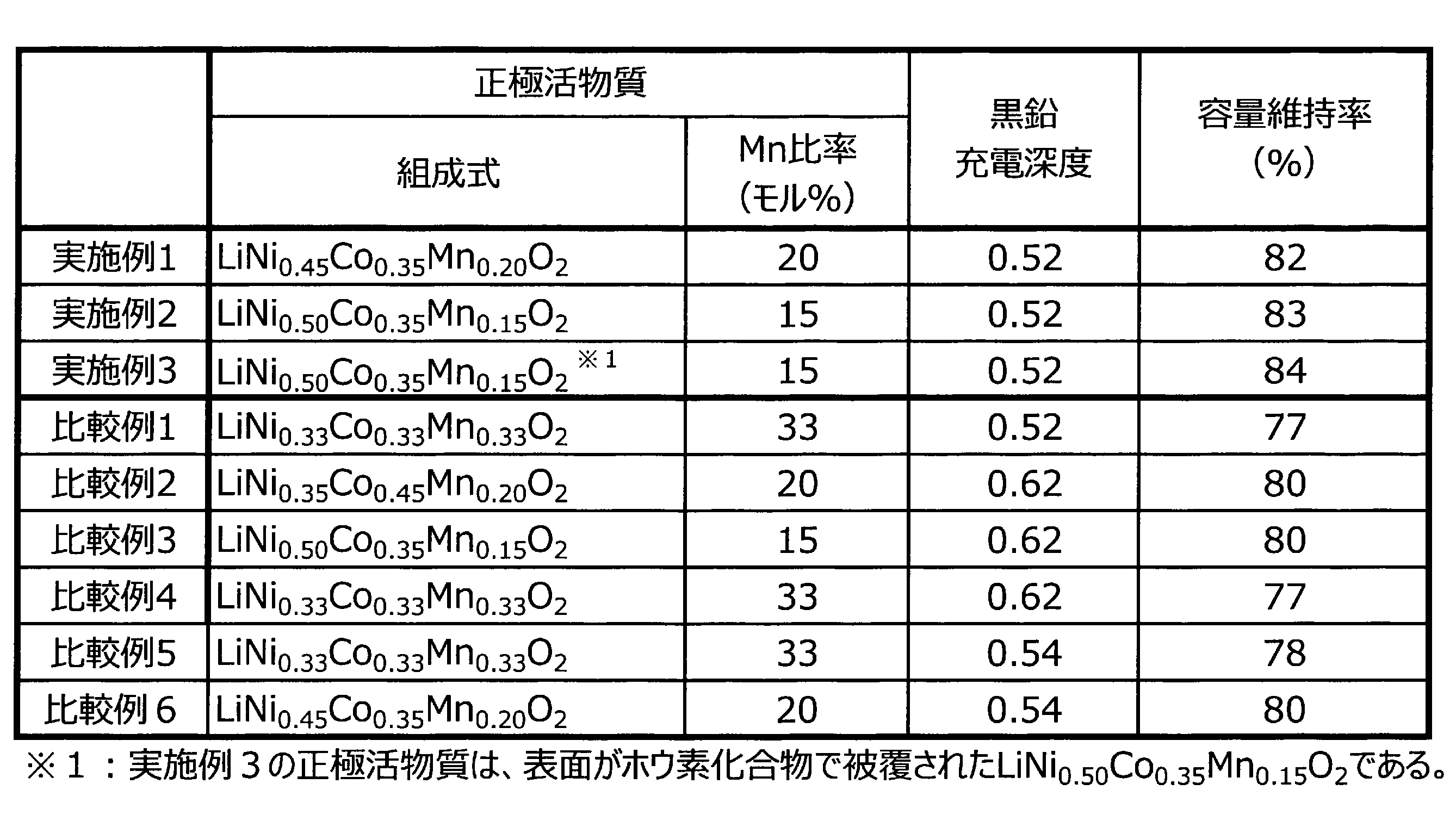
2 電極体
3 容器
4 正極端子
41 正極リード
5 負極端子
51 負極リード
20 蓄電ユニット
30 蓄電装置
Claims (5)
- マンガンを含むリチウム遷移金属複合酸化物を有する正極と、
黒鉛を有する負極と
を備え、
上記リチウム遷移金属複合酸化物におけるリチウムを除く金属元素に占めるマンガンの比率が20モル%以下であり、
充電状態における上記黒鉛の充電深度が0.54未満である非水電解質蓄電素子。 - 上記リチウム遷移金属複合酸化物がニッケル及びコバルトをさらに含む請求項1に記載の非水電解質蓄電素子。
- 上記リチウム遷移金属複合酸化物におけるリチウムを除く金属元素に占めるマンガンの比率が1モル%以上である請求項1又は請求項2に記載の非水電解質蓄電素子。
- 充電状態における上記黒鉛の充電深度が0.40以上である請求項1、請求項2、又は請求項3に記載の非水電解質蓄電素子。
- 請求項1から請求項4のいずれか1項に記載の非水電解質蓄電素子を一以上備える蓄電装置。
Priority Applications (3)
| Application Number | Priority Date | Filing Date | Title |
|---|---|---|---|
| CN202280034296.1A CN117321819A (zh) | 2021-05-28 | 2022-03-16 | 非水电解质蓄电元件和蓄电装置 |
| JP2023524032A JPWO2022249667A1 (ja) | 2021-05-28 | 2022-03-16 | |
| EP22810945.0A EP4322258A1 (en) | 2021-05-28 | 2022-03-16 | Nonaqueous electrolyte power storage element and power storage device |
Applications Claiming Priority (2)
| Application Number | Priority Date | Filing Date | Title |
|---|---|---|---|
| JP2021089962 | 2021-05-28 | ||
| JP2021-089962 | 2021-05-28 |
Publications (1)
| Publication Number | Publication Date |
|---|---|
| WO2022249667A1 true WO2022249667A1 (ja) | 2022-12-01 |
Family
ID=84228614
Family Applications (1)
| Application Number | Title | Priority Date | Filing Date |
|---|---|---|---|
| PCT/JP2022/011770 WO2022249667A1 (ja) | 2021-05-28 | 2022-03-16 | 非水電解質蓄電素子及び蓄電装置 |
Country Status (4)
| Country | Link |
|---|---|
| EP (1) | EP4322258A1 (ja) |
| JP (1) | JPWO2022249667A1 (ja) |
| CN (1) | CN117321819A (ja) |
| WO (1) | WO2022249667A1 (ja) |
Citations (5)
| Publication number | Priority date | Publication date | Assignee | Title |
|---|---|---|---|---|
| JP2005222933A (ja) | 2004-01-05 | 2005-08-18 | Showa Denko Kk | リチウム電池用負極材及びリチウム電池 |
| JP2009199929A (ja) * | 2008-02-22 | 2009-09-03 | Hitachi Ltd | リチウム二次電池 |
| JP2011054371A (ja) * | 2009-09-01 | 2011-03-17 | Hitachi Vehicle Energy Ltd | リチウムイオン二次電池 |
| JP2015018678A (ja) | 2013-07-10 | 2015-01-29 | 株式会社田中化学研究所 | リチウム二次電池用正極活物質、正極および二次電池 |
| JP2017212040A (ja) * | 2016-05-23 | 2017-11-30 | オートモーティブエナジーサプライ株式会社 | リチウムイオン二次電池 |
-
2022
- 2022-03-16 EP EP22810945.0A patent/EP4322258A1/en active Pending
- 2022-03-16 JP JP2023524032A patent/JPWO2022249667A1/ja active Pending
- 2022-03-16 CN CN202280034296.1A patent/CN117321819A/zh active Pending
- 2022-03-16 WO PCT/JP2022/011770 patent/WO2022249667A1/ja active Application Filing
Patent Citations (5)
| Publication number | Priority date | Publication date | Assignee | Title |
|---|---|---|---|---|
| JP2005222933A (ja) | 2004-01-05 | 2005-08-18 | Showa Denko Kk | リチウム電池用負極材及びリチウム電池 |
| JP2009199929A (ja) * | 2008-02-22 | 2009-09-03 | Hitachi Ltd | リチウム二次電池 |
| JP2011054371A (ja) * | 2009-09-01 | 2011-03-17 | Hitachi Vehicle Energy Ltd | リチウムイオン二次電池 |
| JP2015018678A (ja) | 2013-07-10 | 2015-01-29 | 株式会社田中化学研究所 | リチウム二次電池用正極活物質、正極および二次電池 |
| JP2017212040A (ja) * | 2016-05-23 | 2017-11-30 | オートモーティブエナジーサプライ株式会社 | リチウムイオン二次電池 |
Also Published As
| Publication number | Publication date |
|---|---|
| JPWO2022249667A1 (ja) | 2022-12-01 |
| CN117321819A (zh) | 2023-12-29 |
| EP4322258A1 (en) | 2024-02-14 |
Similar Documents
| Publication | Publication Date | Title |
|---|---|---|
| JP2022134613A (ja) | 非水電解質蓄電素子用正極合剤、非水電解質蓄電素子用正極及び非水電解質蓄電素子 | |
| WO2022249667A1 (ja) | 非水電解質蓄電素子及び蓄電装置 | |
| WO2022181516A1 (ja) | 非水電解質蓄電素子 | |
| WO2023100801A1 (ja) | 非水電解質蓄電素子、機器及び非水電解質蓄電素子の使用方法 | |
| WO2022230835A1 (ja) | 非水電解質蓄電素子 | |
| WO2023281960A1 (ja) | 正極、蓄電素子及び蓄電装置 | |
| WO2022202576A1 (ja) | 非水電解質蓄電素子 | |
| WO2022209815A1 (ja) | 非水電解質蓄電素子用正極活物質、非水電解質蓄電素子用正極、非水電解質蓄電素子、蓄電ユニット及び蓄電装置 | |
| WO2023286718A1 (ja) | 蓄電素子 | |
| WO2023190422A1 (ja) | 非水電解質蓄電素子用の正極及びこれを備える非水電解質蓄電素子 | |
| WO2023248769A1 (ja) | 活物質粒子、電極、蓄電素子及び蓄電装置 | |
| WO2023276863A1 (ja) | 非水電解質蓄電素子 | |
| WO2023224070A1 (ja) | 非水電解質蓄電素子 | |
| WO2023224071A1 (ja) | 非水電解質蓄電素子 | |
| WO2024062862A1 (ja) | 電極、蓄電素子及び蓄電装置 | |
| WO2024010016A1 (ja) | 非水電解質蓄電素子、機器、非水電解質蓄電素子の使用方法及び非水電解質蓄電素子の製造方法 | |
| WO2024029333A1 (ja) | 非水電解質蓄電素子 | |
| WO2023074559A1 (ja) | 蓄電素子 | |
| WO2022168845A1 (ja) | 非水電解質蓄電素子、及び蓄電装置 | |
| WO2023167235A1 (ja) | 蓄電素子及び蓄電装置 | |
| WO2023032751A1 (ja) | 非水電解質蓄電素子用の正極、非水電解質蓄電素子及び蓄電装置 | |
| WO2023090333A1 (ja) | 非水電解質蓄電素子 | |
| WO2023145677A1 (ja) | 非水電解質蓄電素子 | |
| WO2022239520A1 (ja) | 蓄電素子、その製造方法及び蓄電装置 | |
| WO2022239861A1 (ja) | 蓄電素子 |
Legal Events
| Date | Code | Title | Description |
|---|---|---|---|
| 121 | Ep: the epo has been informed by wipo that ep was designated in this application |
Ref document number: 22810945 Country of ref document: EP Kind code of ref document: A1 |
|
| ENP | Entry into the national phase |
Ref document number: 2023524032 Country of ref document: JP Kind code of ref document: A |
|
| WWE | Wipo information: entry into national phase |
Ref document number: 2022810945 Country of ref document: EP |
|
| WWE | Wipo information: entry into national phase |
Ref document number: 18563034 Country of ref document: US |
|
| ENP | Entry into the national phase |
Ref document number: 2022810945 Country of ref document: EP Effective date: 20231108 |
|
| NENP | Non-entry into the national phase |
Ref country code: DE |