WO2022244306A1 - 映像判別装置、映像判別システム、及び記憶媒体 - Google Patents
映像判別装置、映像判別システム、及び記憶媒体 Download PDFInfo
- Publication number
- WO2022244306A1 WO2022244306A1 PCT/JP2022/002289 JP2022002289W WO2022244306A1 WO 2022244306 A1 WO2022244306 A1 WO 2022244306A1 JP 2022002289 W JP2022002289 W JP 2022002289W WO 2022244306 A1 WO2022244306 A1 WO 2022244306A1
- Authority
- WO
- WIPO (PCT)
- Prior art keywords
- machine
- data
- state
- image
- unit
- Prior art date
- Legal status (The legal status is an assumption and is not a legal conclusion. Google has not performed a legal analysis and makes no representation as to the accuracy of the status listed.)
- Ceased
Links
Images







Classifications
-
- H—ELECTRICITY
- H04—ELECTRIC COMMUNICATION TECHNIQUE
- H04N—PICTORIAL COMMUNICATION, e.g. TELEVISION
- H04N7/00—Television systems
- H04N7/18—Closed-circuit television [CCTV] systems, i.e. systems in which the video signal is not broadcast
-
- G—PHYSICS
- G06—COMPUTING OR CALCULATING; COUNTING
- G06V—IMAGE OR VIDEO RECOGNITION OR UNDERSTANDING
- G06V20/00—Scenes; Scene-specific elements
- G06V20/40—Scenes; Scene-specific elements in video content
- G06V20/46—Extracting features or characteristics from the video content, e.g. video fingerprints, representative shots or key frames
- G06V20/47—Detecting features for summarising video content
-
- G—PHYSICS
- G05—CONTROLLING; REGULATING
- G05B—CONTROL OR REGULATING SYSTEMS IN GENERAL; FUNCTIONAL ELEMENTS OF SUCH SYSTEMS; MONITORING OR TESTING ARRANGEMENTS FOR SUCH SYSTEMS OR ELEMENTS
- G05B19/00—Program-control systems
- G05B19/02—Program-control systems electric
- G05B19/18—Numerical control [NC], i.e. automatically operating machines, in particular machine tools, e.g. in a manufacturing environment, so as to execute positioning, movement or co-ordinated operations by means of program data in numerical form
- G05B19/406—Numerical control [NC], i.e. automatically operating machines, in particular machine tools, e.g. in a manufacturing environment, so as to execute positioning, movement or co-ordinated operations by means of program data in numerical form characterised by monitoring or safety
-
- G—PHYSICS
- G05—CONTROLLING; REGULATING
- G05B—CONTROL OR REGULATING SYSTEMS IN GENERAL; FUNCTIONAL ELEMENTS OF SUCH SYSTEMS; MONITORING OR TESTING ARRANGEMENTS FOR SUCH SYSTEMS OR ELEMENTS
- G05B19/00—Program-control systems
- G05B19/02—Program-control systems electric
- G05B19/18—Numerical control [NC], i.e. automatically operating machines, in particular machine tools, e.g. in a manufacturing environment, so as to execute positioning, movement or co-ordinated operations by means of program data in numerical form
- G05B19/406—Numerical control [NC], i.e. automatically operating machines, in particular machine tools, e.g. in a manufacturing environment, so as to execute positioning, movement or co-ordinated operations by means of program data in numerical form characterised by monitoring or safety
- G05B19/4063—Monitoring general control system
-
- Y—GENERAL TAGGING OF NEW TECHNOLOGICAL DEVELOPMENTS; GENERAL TAGGING OF CROSS-SECTIONAL TECHNOLOGIES SPANNING OVER SEVERAL SECTIONS OF THE IPC; TECHNICAL SUBJECTS COVERED BY FORMER USPC CROSS-REFERENCE ART COLLECTIONS [XRACs] AND DIGESTS
- Y02—TECHNOLOGIES OR APPLICATIONS FOR MITIGATION OR ADAPTATION AGAINST CLIMATE CHANGE
- Y02P—CLIMATE CHANGE MITIGATION TECHNOLOGIES IN THE PRODUCTION OR PROCESSING OF GOODS
- Y02P90/00—Enabling technologies with a potential contribution to greenhouse gas [GHG] emissions mitigation
- Y02P90/02—Total factory control, e.g. smart factories, flexible manufacturing systems [FMS] or integrated manufacturing systems [IMS]
Definitions
- the present invention relates to a video discrimination device, a video discrimination system, and a computer-readable storage medium.
- Multimedia NC control device that supports manufacturing activities (repeat orders) by reproducing machine operation and setup for each product, or product handling and inspection methods with images (Patent Document 1 )” exists.
- NC machining data is downloaded to the NC device, and an index table 26 is created with the program name as an ID.
- the bar code reading switch 13 is provided with a plurality of code switches for each operation, such as a "setup code” operated during mold setup and a "bending code” pressed during bending. For example, when a "setup code” is operated, the system enters that time code in the "setup process” column of the index table 26.
- FIG. The system manages the NC processing data (program) and the index table 26 as a pair, and can be searched by the reproducing section 24 .
- Patent Document 1 it is necessary to prepare a switch for starting video recording and a switch for selecting the content to be recorded (arrangement, bending, etc.). must be entered.
- a numerical control device which is one aspect of the present disclosure, includes identification information of data relating to the state of a machine, which is both the numerical control device and the machine tool, or at least one of them, and a machine state dictionary unit that links the contents of the data.
- an image acquisition unit that acquires an image of the machine
- a machine condition acquisition unit that acquires data used for detecting a change in the condition of the machine
- a machine state conversion unit that refers to the state dictionary unit and converts the change in the data into the operation content of the machine, a data string that links the image when the state of the machine changes, and the content of the data. and a mounting portion.
- a video discrimination system which is one aspect of the present disclosure, includes identification information of data relating to the state of a machine, which is both a numerical control device and a machine tool, or at least one of them, and a machine state dictionary unit that links the content of the data.
- an image acquisition unit that acquires an image of the machine
- a machine condition acquisition unit that acquires data used for detecting a change in the condition of the machine
- a data linking unit that refers to the state dictionary unit, converts the change in the data into the operation content of the machine, and links the image when the state of the machine changes with the content of the data
- the storage medium which is one aspect of the present disclosure, is executed by one or more processors to provide identification information of data relating to the state of a machine, which is both a numerical control device and a machine tool, or at least one of the data; store a machine state dictionary that associates the contents of the machine with the content of the machine, acquire the image of the machine, acquire data used to detect the change in the state of the machine, and determine whether the state of the machine has changed based on the data.
- a computer-readable command is stored that determines whether or not there is a change in the state of the machine, and associates an image when the state of the machine changes with the content of the data. storage medium.
- images can be automatically discriminated.
- FIG. 1 is a block diagram of a numerical control device as a video discriminating device of the first disclosure;
- FIG. It is a figure which shows each variable set on the memory of a numerical controller. It is a conceptual diagram which shows the relationship between a numerical control device and an external device. It is a figure which shows an example of an input part.
- FIG. 11 is a block diagram of a numerical controller of the second disclosure; It is a figure which shows an example of an operation signal dictionary part.
- FIG. 10 is a diagram for explaining selection of a keyframe; It is a figure which shows an example of an operation signal dictionary part.
- FIG. 10 is a diagram showing an example of a video created by an operation video creation unit;
- FIG. 10 is a diagram showing an example of a video created by an operation video creation unit;
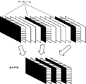
- FIG. 10 is a diagram for explaining creation of a summary video; It is a figure which shows an example of the image
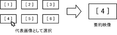
- FIG. 10 is a diagram for explaining selection of a representative video;
- FIG. 4 is a flowchart for explaining the operation of the numerical control device;
- It is a block diagram of a numerical controller of the third disclosure. It is a figure which shows the hardware constitutions of a numerical controller.
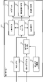
- FIG. 1 is a block diagram of a numerical control device 100 as a video discriminating device of the first disclosure.
- the numerical control device 100 includes an image acquisition section 1 , a machine state acquisition section 2 , a machine state dictionary section 3 , a machine state conversion section 4 and a data linking section 5 .
- the image acquisition unit 1 acquires an image from a camera 6 that captures an image of the machine tool 7 or a captured image of the display screen of the numerical control device 100 or the machine tool 7 .
- the machine state acquisition unit 2 acquires data used to detect changes in the state of the machine tool 7 and the numerical controller 100 that controls the machine tool 7 (hereinafter, data used to detect changes in the state of the machine).
- Data used to detect changes in the state of the machine include operation signals from the machine operation panel or touch panel, variable changes from machining programs, variable changes from built-in programs, variable changes from PC applications, and connections to machine tools. input signals from external equipment connected to machine tools, output signals to external equipment connected to machine tools, machining program commands, sequence program commands, and the like.
- the machine state dictionary unit 3 stores “identification information of data used to detect changes in the state of the machine (e.g., identification information of signals/identification information of variables/identification information of commands)” and “identification information of data used to detect changes in the state of the machine.” data content (for example, signal content/variable content/command content)”.
- the machine state conversion unit 4 monitors the "data used for detecting a change in the state of the machine" acquired by the machine state acquisition unit 2, determines whether or not the machine state has changed, and if a change in the machine state occurs, By referring to the machine state dictionary, the "data identification information" is converted into “data content”.
- the data linking unit 5 links changes in the state of the machine with images of the machine. Specifically, both or at least one of the “data value indicating the state change of the machine” and the “content of the data causing the state change of the machine” is associated with the image acquired by the image acquisition unit 1 .
- the images acquired by the image acquisition unit 1 include images captured by the camera 6 that captures the machine tool 7 and captured images of the display screen of the machine tool 7 .
- An operation signal from an operation panel, a touch panel, or the like can be "data used to detect changes in the state of the machine.”
- the machine state conversion unit 4 monitors the operation signal, and when the operation signal changes, refers to the machine state dictionary unit 3 and reads out the "data content” of the changed operation signal.
- the data linking unit links both or at least one of the "data value” and the "data content” with the video. For example, when the operator manually operates the speed dial on the operation panel and the speed signal changes from “10 to 20", the data linking unit 5 generates an image of "the movement speed of the machine tool axis changes" and the contents of the data. "Speed” is associated with the data value "10->20". For example, when a "processing start button" on the touch panel is pressed to change the processing start signal from OFF to ON, the data linking unit 5 displays an image “processing of workpiece starts” and data content "processing starts”. , to tie.
- the machine state conversion unit 4 detects the block (row) where the machining program has changed. For example, when the 100th line of the machining program changes, the data linking unit 5 associates the image "operator operates the touch panel", the data content "change in machining program", and the data value "100th line”. , to tie.
- the data associating unit 5 associates an image of “an operator operating a touch panel or an operation panel”, a data content “feed speed parameter”, and a data value “100->200”.
- the data associating unit 5 associates the image "operator operates the touch panel or operation panel", the data content "tool offset”, and the data value "100mm->110mm".
- the data linking unit 5 includes an image of "a machining program for measuring the tool length is executed, and the measurement result is reflected in the offset", the data content "tool offset”, and the data value, for example, "100mm->110mm ” and tie it.
- the image “the measurement result is reflected in the offset” may be a captured image of the display unit 70 of the numerical control device 100 .
- macro variables automatically change. For example, when a machining program that automatically changes macro variables is executed, macro variables for the shape of the work are automatically changed.
- the data linking unit 5 includes a “work measurement execution” image, a “measurement result reflected in macro variables” image, data content “work shape”, and a data value such as “X120.0- >X124.0”.
- the image “measurement results are reflected in the macro variables” may be, for example, a captured image on the display unit 70 of the numerical control device 100 .
- the data linking unit 5 connects the image ⁇ the number of the machining program is changed'' and the content of the data ⁇ the machining program to be executed number” and the data value “machining program number” are linked.
- the image “the machining program number is changed” may be a captured image on the display unit 70 of the numerical controller 100 .
- An application of an external information device may change variables of the numerical controller 100 .
- the external information device is a PC (personal computer), a server, or the like.
- the data linking unit will link the image “the number of the machining program is changed” and the content of the data "the number of the machining program to be executed”. , and the data value “machining program number”.
- the “name of the application that changed the variable” the "name of the external information device that changed the variable” and the like can be used.
- the image “the machining program number is changed” may be a captured image on the display unit 70 of the numerical controller 100 .
- An input signal from an external device connected to the machine tool 7 can be "data used to detect changes in the state of the machine".
- the 'contact signal of the touch probe' is 'data used for detecting a change in the state of the machine'.
- the "probe contact signal” changes to "ON”.
- the data linking unit 5 links the image “the LED (Light Emitting Diode) of the touch probe shines and stops” with the content of the data "touch probe contact”.
- Input signals from the sensors can be "data used to detect changes in the state of the machine.”
- the "spindle temperature” detected by the temperature sensor is “data used to detect changes in the state of the machine”.
- the data linking unit 5 links the data content "spindle temperature", the data value "spindle temperature value”, and the image of the "spindle”. As the temperature rises, the "main shaft” may also smoke.
- An output signal to an external device connected to the machine tool 7 can be "data used to detect changes in the state of the machine".
- a 'machine tool door open/close signal' can be 'data used to detect changes in the state of the machine'.
- the PLC the PLC built into the numerical controller 100 or the PLC external to the numerical controller 100
- the data linking unit 5 links the image of the external device and the change in the data.
- the data linking unit 5 when the "door open/close signal” turns ON, the data linking unit 5 generates the image “door opens”, the data content "door open/close signal", the data value "OFF->ON", tie the The “coolant signal” can be "data used to detect changes in the state of the machine.”
- the PLC the PLC built into the numerical controller 100 or the PLC external to the numerical controller 100
- the data linking unit 5 links the image of the external device and the change in the data. For example, when the "coolant signal” turns ON, the data linking unit 5 connects the image “coolant spouting starts", the data content "coolant signal", and the data value "OFF->ON”.
- the commands of the machining program can be "data used to detect changes in the state of the machine".
- the numerical controller 100 analyzes the machining program and outputs commands to modules such as servo amplifiers. When outputting the command, the "signal indicating the state of the specific function of the numerical controller 100" changes.
- the machine state conversion unit 4 changes the state of the machine based on a change in the value (for example, switching between ON and OFF) of a "signal indicating the state of a specific function (for example, fast feed) of the numerical controller 100.” determine that it has changed.
- the data associating unit 5 associates an image "using a specific function of the numerical controller 100" with data content "for example, a fast-forward command".
- the command of the sequence program can be "data used to detect changes in the state of the machine".
- the PLC inside the numerical controller 100 analyzes the sequence program and commands specific sequence functions to external devices connected to the numerical controller 100 .
- the "signal indicating the status of the sequence function” changes.
- the machine state conversion unit 4 determines that the state of the machine has changed based on a change in the value of the "signal indicating the state of the sequence function" (for example, switching between ON and OFF).
- the data associating unit 5 associates an image of "a command of a sequence program is executed" with a data content "for example, a tool change command".
- variables such as local variables, macro variables, common variables, and system variables are set in the memory of the numerical controller 100, as shown in FIG.
- a parameter number is also determined.
- Variable numbers and parameter numbers can be used as data identification information.
- a local variable is a variable used when executing a machining program such as a main program or a macro program, and is independent between the main program and the macro program.
- a common variable is a variable commonly used by the main program and the macro program.
- the system variables store changes in tool diameter compensation, reading of coordinate values, valid commands (G codes), valid M codes (sequence commands), and the like.
- System variables include interface input signals, interface output signals, setting data, modal information, and the like. Changes in the machine state can be detected from the values of these variables.
- the numerical controller 100 of the first disclosure detects changes in the machine state by monitoring memory, external signals, operation signals, etc., refers to the machine state dictionary unit 3, and identifies machine state identification information as " “Contents of data” and link the "contents of data” with the video. This makes it possible to determine the content of the video.
- the second disclosure shows an application example using a video associated with "data content”.
- FIG. 3 is a conceptual diagram showing a numerical control device 100 as a video discriminating device of the present disclosure and a device that transmits signals to the numerical control device 100.
- the numerical controller 100 is included in a machining center.
- a machining center is an apparatus in which the numerical control device 100 and a machine tool are integrated. Machining centers also include devices such as servomotors, fans, fog collectors, coolant, chip removers, automatic tool changers (ATC), and stack indicator lights (Patlite®).
- the numerical controller 100 has an internal PLC (Programmable Logic Controller) 42 to control these devices.
- PLC Programmable Logic Controller
- the PLCs 42 and 50 include an internal PLC 42 built into the numerical controller 100 and an external PLC 50 .
- the external PLC 50 receives signals from equipment, devices, sensors, and actuators existing at the manufacturing site, and outputs information detected by the sensors and control state data to the numerical controller 100. output to In this disclosure, devices controlled by the PLCs 42 and 50 are called external devices of the numerical controller 100 .
- the numerical controller 100 has an input unit 71 .
- the input section 71 includes a physical input section 71 and an electronic input section 71 .
- FIG. 4 shows an example of the input unit 71 of the numerical controller 100.
- a physical input unit 71 is a dial, button, or the like of a machine operation panel.
- the electronic input unit 71 is, for example, buttons displayed on a touch panel.
- This operation signal is not a special signal, but an existing operation signal obtained as a result of the operator's input to the existing input unit 71 of the numerical controller 100 .
- existing operation signals are used for video discrimination. There is no need for the operator to input the operation content, and no special switch or the like for the operator to input the operation content is required.
- FIG. 5 is a block diagram of the numerical controller 100.
- the numerical control device 100 includes a video acquisition unit 11, an operation signal acquisition unit 12, an operation signal dictionary unit 13, an operation signal conversion unit 14, a data linking unit 15, a subtitle creation unit 16, a video creation unit 17, and a summary video creation unit 18. , a procedure manual creation unit 19 and an image selection unit 20 .
- the image acquisition unit 11 provides the image acquisition unit 1 described in the first disclosure
- the operation signal acquisition unit 12 provides the machine state acquisition unit 2 described in the first disclosure with the operation according to the present disclosure.
- the signal dictionary unit 13 links data according to the present disclosure to the machine state dictionary unit 3 described in the first disclosure
- the operation signal conversion unit 14 according to the present disclosure links the data to the machine state conversion unit 4 described in the first disclosure.
- the units 15 respectively correspond to the data linking units 5 described in the first disclosure.
- the image acquisition unit 11 acquires images from a camera (not shown) that captures images of the machine tool.
- the operation signal acquisition unit 12 acquires an operation signal input to the input unit 71 of the machine operation panel or touch panel.
- the operation signal dictionary unit 13 associates "signals”, “signal values”, and "operation details”.
- the operation signal conversion unit 14 can convert the change in the signal input to the numerical control device 100 into the details of the operator's operation.
- FIG. 6 shows an example of the operation signal dictionary unit 13. As shown in FIG. In FIG. 6, "signal 1" and “signal 2" are registered as “signal”.
- the “signal” includes an input address of an external device, a voltage value of a predetermined resistance, and the like.
- the value “1" of "signal 1" is associated with the operation content "move in +Y direction with JOG”.
- the value "10" of "signal 2" is associated with the operation content "fast forward override is 25%”.
- the operation signal conversion unit 14 monitors the operation signal input to the input unit 71 and detects changes in the operation signal. Changes in the operation signal include changes in the value of the operation signal, input of a new operation signal, stoppage of input of the operation signal, and the like. In the example of the first row in FIG. 6, when the value of "signal 1" changes from “0" to "1", a change in the operation signal is detected.
- the operation signal conversion unit 14 refers to the operation signal dictionary unit 13 and converts the change in the operation signal into the operation content “move in JOG+Y direction”.
- the data linking unit 15 links the operation content and the video.
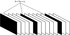
- the data linking unit 15 selects the image at the time when the operation signal changes as a key frame.
- a key frame is a frame that serves as a delimiter in data that constitutes a moving image.
- a keyframe is an uncompressed frame that completely retains the video information. As shown in FIG. 7, the data linking unit 15 selects a key frame at the time when the operation data changes from among the plurality of frames, and links it with the operation content.
- the caption creation unit 16 creates captions indicating the details of the operation at the time when there was a change in the signal.
- One way to create subtitles is to create a subtitle file.
- a subtitle file is a text file in which subtitle display time and subtitle text are associated with each other.
- the subtitle creation unit 16 adds a subtitle file to the video.
- video, audio, and subtitles may be multiplexed at the time of video compression like an MPEG transport stream. There are no particular restrictions on how to create subtitles.
- the image creation unit 17 converts the operation content into an image.
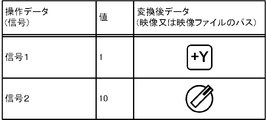
- FIG. 8 shows an example of the operation signal dictionary unit 13 when converting operation contents into video.
- the value “1" of "signal 1” is associated with the operation content "+Y” button.
- a “signal 2" value of "10” is associated with the image of the dial being operated counterclockwise.
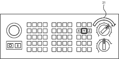
- FIG. 9 is an example of a video created by the video creation unit 17. As shown in FIG. FIG. 9 shows the pressing of the button “Y” and the dialing operation as the operation contents. Specifically, the button “Y” is highlighted, an arrow indicating that the dial on the upper right of the machine control panel has been rotated is displayed, and the operation amount (value) of the dial is indicated.
- the image creation unit 17 converts the operation content of the operator into an image.
- the summary video creation unit 18 extracts and connects the key frame selected by the data linking unit 15 and the video for several seconds after that, so that only the portion where the operation data has changed is extracted. Create an aggregate summary video. Subtitles may be added to the summary video.
- FIG. 9 shows an example in which subtitles are added to a summary video. In the example of FIG. 11, the subtitle is "JOG + move in Y direction". By adding subtitles, it is possible to visualize the relationship between the operator's operation and the movement of the machine tool.
- the procedure manual creation unit 19 creates an operation procedure manual in which the video and the operation contents correspond one-to-one by pasting the key frames and the text representing the operation contents at that time to the document file in order.
- key frame [1] is the image when the operation of "JOG + Y direction” is performed
- key frame [2] is the image when the operation of "change to automatic driving mode” is performed
- key frame [3] is "
- the key frame [4] is an image when an operation of "pressing the start button" is performed.
- a procedure manual can be automatically created by arranging operator operations in chronological order.
- the operating procedure manual may include time information. Subtitles may be added to the video.
- the image selection unit 20 receives selection of a representative image used to create a summary image or a procedure manual.
- the video selection unit 20 displays a list of key frames at the time when the signal changes, and accepts a user's selection.
- a summary video creation unit 18 creates a summary video from the keyframes selected by the user.
- the procedure manual creation unit 19 creates a procedure manual from the keyframes selected by the user.
- the image selection unit 20 can also select a representative image.
- the representative video is used as a summary video or a cover video of a procedure manual. In the example of FIG. 13, when the keyframe [4] is selected as the representative video from the list of keyframes [1] to [6], a summary video is created with the keyframe [4] as the cover. showing the situation.
- the operation of the numerical controller 100 will be described with reference to the flowchart of FIG. In the present disclosure, the numerical control device 100 performs video recording and video discrimination at the same time.
- the numerical controller 100 acquires an image of the machine tool from the connected camera (step S1), and simultaneously acquires an operation signal (step S2).
- the numerical controller 100 monitors the operation signal (step S3), and when detecting a change in the operation signal (step S4; YES), refers to the operation signal dictionary unit 13 and selects the operation content corresponding to the operation signal. If no change in the operation signal is detected in step S4 (step S4; NO), the process proceeds to step S3 to monitor the operation signal.
- the numerical control device 100 selects the video frame at the time when the operation signal changes as a key frame, and associates it with the operation content (step S5).
- the keyframes and operation contents are stored (step S6). At this time, a time stamp may be added.
- the numerical controller 100 of the present disclosure includes an operation signal dictionary unit 13 that associates an operation signal with an operation content, and stores an operation content and a key frame generated when an operator operates the numerical controller 100 in association with each other. .
- the numerical control device 100 converts the operation content into a human-readable format such as text or video.
- Numerical control device 100 displays text indicating operation details as subtitles, or displays operation details as video.
- Numerical controller 100 uses the operation content and key frames to create a summary video or a procedure manual. The user can also select a keyframe that will be the cover of the summary video or procedure manual. Note that the operation content may be converted into voice.
- the image discrimination device 200 of the third disclosure includes, as shown in FIG. 15, an image storage unit 21 that stores recorded images and a data storage unit 22 that stores operation signals being processed.
- the image acquisition unit 11 reads images stored in the image storage unit 21
- the operation signal acquisition unit 12 reads operation signals stored in the data storage unit 22 .
- the operation signal dictionary unit 13, the operation signal conversion unit 14, the data linking unit 15, the subtitle creation unit 16, the video creation unit 17, the summary video creation unit 18, the procedure manual creation unit 19, and the video selection unit 20 are the same as those described in the second disclosure. Since the same processing is performed as in , the explanation is omitted.
- the image discrimination device 200 of the third disclosure can be applied to information processing devices such as numerical control devices, PCs, servers, and mobile terminals. Further, the present disclosure also includes a video discrimination system in which the components of the video discrimination device 200 of the third disclosure are distributed and arranged such as a PC, a server, a numerical control device, etc. on a network.
- each function creates subtitles, summaries, procedure manuals, and representative images, and stores data based on data indicating various states of the machine as well as the details of operation.
- the numerical control device 100 is used as an application example of the image discrimination device, but the image acquisition unit 1 (image acquisition unit 11), the machine state acquisition unit 2 (operation signal acquisition unit 12), the machine condition acquisition unit 2 (operation signal acquisition unit 12), If the state dictionary unit 3 (operation signal dictionary unit 13), the mechanical state conversion unit 4 (operation signal conversion unit 14), and the data linking unit 5 (data linking unit 15) exist, information processing other than the numerical control device 100 It may be applied to the device.
- the present disclosure also includes an image discrimination system in which the components of the numerical control device 100 are distributed in PCs (personal computers), servers, numerical control devices, etc. on a network.
- a CPU 111 included in the numerical controller 100 is a processor that controls the numerical controller 100 as a whole.
- the CPU 111 reads the system program processed in the ROM 112 via the bus and controls the entire numerical controller 100 according to the system program.
- the RAM 113 temporarily stores calculation data, display data, various data input by the user via the input unit 71, and the like.
- the display unit 70 is a monitor attached to the numerical controller 100 or the like.
- the display unit 70 displays an operation screen, a setting screen, and the like of the numerical controller 100 .
- the input unit 71 is integrated with the display unit 70 or is a keyboard, touch panel, or the like that is separate from the display unit 70 .
- the user operates the input unit 71 to perform input to the screen displayed on the display unit 70 .
- the display unit 70 and the input unit 71 may be mobile terminals.
- the non-volatile memory 114 is, for example, a memory that is backed up by a battery (not shown) so that the memory state is retained even when the power of the numerical controller 100 is turned off.
- the nonvolatile memory 114 stores programs read from an external device via an interface (not shown), programs input via the input unit 71, and various data (for example, , setting parameters obtained from the machine tool, etc.) are stored. Programs and various data stored in the non-volatile memory 114 may be developed in the RAM 113 at the time of execution/use. Various system programs are pre-written in the ROM 112 .
- the controller 40 that controls the tool of the machine tool converts the axis movement command from the CPU 111 into a pulse signal and outputs it to the driver 41 .
- a driver 41 converts the pulse signal into a current to drive a servomotor of the machine tool.
- a servo motor moves a tool and a table according to control of the numerical controller 100.
- REFERENCE SIGNS LIST 100 numerical control device 200 image discrimination device 1 image acquisition unit 2 machine state acquisition unit 3 machine state dictionary unit 4 machine state conversion unit 5 data linking unit 11 image acquisition unit 12 operation signal acquisition unit 13 operation signal dictionary unit 14 operation signal conversion Unit 15 Data linking unit 16 Subtitle creation unit 17 Video creation unit 18 Summary video creation unit 19 Procedure manual creation unit 20 Video selection unit 111 CPU 112 ROMs 113 RAM 114 non-volatile memory
Landscapes
- Engineering & Computer Science (AREA)
- Physics & Mathematics (AREA)
- General Physics & Mathematics (AREA)
- Human Computer Interaction (AREA)
- Manufacturing & Machinery (AREA)
- Automation & Control Theory (AREA)
- Multimedia (AREA)
- Theoretical Computer Science (AREA)
- Signal Processing (AREA)
- Numerical Control (AREA)
Abstract
Description
本開示の一態様である映像判別システムは、数値制御装置又は工作機械の両方、又は少なくとも一方である機械の状態に係るデータの識別情報と、該データの内容とを紐づける機械状態辞書部と、前記機械の映像を取得する映像取得部と、前記機械の状態変化の検出に用いるデータを取得する機械状態取得部と、前記データを基に、前記機械の状態の変化を検出し、前記機械状態辞書部を参照して、前記データの変化を前記機械の操作内容に変換し、前記機械の状態が変化したときの映像と、前記データの内容と、を紐づけるデータ紐づけ部と、を備える。
本開示の一態様である記憶媒体は、1つ又は複数のプロセッサが実行することにより、数値制御装置又は工作機械の両方、又は少なくとも一方である機械の状態に係るデータの識別情報と、該データの内容とを紐づける機械状態辞書部を記憶し、前記機械の映像を取得し、前記機械の状態変化の検出に用いるデータを取得し、前記データを基に、前記機械の状態が変化したか否かを判断し、前記機械の状態が変化したときの映像と、前記データの内容と、を紐づける、コンピュータが読み取り可能な命令を記憶する。
記憶媒体。
図1は、第1の開示の映像判別装置としての数値制御装置100のブロック図である。
数値制御装置100は、映像取得部1、機械状態取得部2、機械状態辞書部3、機械状態変換部4、データ紐づけ部5を備える。
操作盤やタッチパネルなどの操作信号は、「機械の状態変化の検出に用いるデータ」となりうる。機械状態変換部4は、操作信号を監視し、操作信号が変化した場合には、機械状態辞書部3を参照し、変化した操作信号の「データの内容」を読み出す。データ紐づけ部は、「データの値」及び「データの内容」の両方、又は少なくとも一方と、映像と紐づける。
例えば、オペレータが操作盤の速度ダイヤルを手動操作し、速度信号が「10から20」に変化すると、データ紐づけ部5は、「工作機械軸の移動速度が変化する」映像と、データの内容「速度」と、データの値「10->20」と、を紐づける。
例えば、タッチパネルの「加工開始ボタン」の押下により、加工開始信号がOFFからONに変化すると、データ紐づけ部5は、「ワークの加工が開始する」映像と、データの内容「加工開始」と、を紐づける。
例えば、変数として、「実行する加工プログラムの番号」が変更された場合、データ紐づけ部は、「加工プログラムの番号が変更される」映像と、データの内容「実行する加工プログラムの番号」と、データの値「加工プログラムの番号」と、を紐づける。
ここで、映像に紐づけるデータの内容は、「変数の変更を実行したアプリケーションの名称」「変数の変更を実行した外部の情報機器の名称」なども用いることができる。「加工プログラムの番号が変更される」映像は、数値制御装置100の表示部70のキャプチャ映像でもよい。
センサからの入力信号は、「機械の状態変化の検出に用いるデータ」となりうる。例えば、温度センサが検出する「主軸温度」は、「機械の状態変化の検出に用いるデータ」である。「主軸温度」が所定の値を超えると、データ紐づけ部5は、データの内容「主軸温度」と、データの値「主軸温度の値」と、「主軸」の映像と、を紐づける。温度が上昇すると、「主軸」は、発煙することもある。
例えば、「工作機械のドア開閉信号」は、「機械の状態変化の検出に用いるデータ」となりうる。「ドアの開閉信号」が変化すると、PLC(数値制御装置100に内蔵のPLC、又は、数値制御装置100の外部のPLC)は、信号の値に従いドアの開閉を行う。データ紐づけ部5は、外部機器の映像と、データの変化とを紐づける。例えば、「ドアの開閉信号」がONになると、データ紐づけ部5は、「ドアが開く」映像と、データの内容「ドアの開閉信号」と、データの値「OFF->ON」と、を紐づける。
「クーラント信号」は、「機械の状態変化の検出に用いるデータ」となりうる。「クーラント信号」が変化すると、PLC(数値制御装置100に内蔵のPLC、又は、数値制御装置100の外部のPLC)は、信号の値に従いクーラントの噴出を行う。データ紐づけ部5は、外部機器の映像と、データの変化を紐づける。例えば、「クーラント信号」がONになると、データ紐づけ部5は、「クーラントの噴出が開始する」映像と、データの内容「クーラント信号」と、データの値「OFF->ON」と、を紐づける。
数値制御装置100では、図2に示すように、ローカル変数、マクロ変数、コモン変数、システム変数などの変数が数値制御装置100のメモリ上に設定されている。また、パラメータ番号も決まっている。変数の番号やパラメータの番号をデータの識別情報として用いることができる。
ローカル変数は、メインプログラムやマクロプログラムなどの加工プログラムの実行時に用いる変数であり、メインプログラムとマクロプログラムでそれぞれ独立している。コモン変数は、メインプログラムとマクロプログラムで共通に使用する変数である。
システム変数は、工具径補正の変更や、座標値の読込み、有効な指令(Gコード)、有効なMコード(シーケンス指令)などを記憶する。システム変数には、インタフェース入力信号、インタフェース出力信号、セッティングデータ、モーダル情報などがある。
これらの変数の値から機械状態の変化を検出することができる。
本開示では、機械状態の内で、特にオペレータによる数値制御装置の操作に着目して映像との紐づけを行う実施形態について説明する。
図3は、本開示の映像判別装置としての数値制御装置100と、数値制御装置100に信号を送信する装置とを示す概念図である。図3において数値制御装置100は、マシニングセンタに含まれる。マシニングセンタは、数値制御装置100と工作機械が一体になった装置である。マシニングセンタは、サーボモータ、ファン、集霧機、クーラント、切粉除去装置、自動工具交換装置(ATC)、積層表示灯(パトライト(登録商標))などの装置も含む。数値制御装置100は、内部PLC(Programmable Logic Controller)42を備え、これらの機器を制御する。
オペレータの操作を時系列に並べることで手順書が自動的に作成できる。操作手順書には、時間情報を含めてもよい。映像に字幕を付けてもよい。
映像選択部20では、代表映像を選択することもできる。代表映像は、要約映像や手順書の表紙映像として用いられる。図13の例では、[1]乃至[6]のキーフレームの一覧から、[4]のキーフレームが代表映像として選択されると、キーフレーム[4]を表紙とする要約映像が作成される様子を示している。
第2の開示では、映像の録画とデータの紐づけとを同時に行ったが、第3の開示では、加工中に録画した映像と加工中の操作信号を用いてデータの紐づけを行う。第3の開示の映像判別装置200は、図15に示すように、録画した映像を記憶する映像記憶部21と、加工中の操作信号を記憶するデータ記憶部22とを備える。映像取得部11は映像記憶部21に記憶する映像を読み出し、操作信号取得部12はデータ記憶部22に記憶する操作信号を読み出す。
例えば、第2の開示で示した字幕作成部16、要約映像作成部18、手順書作成部19、映像選択部20、第3の開示で示した映像記憶部21、データ記憶部22などの機能は、第1の開示に係る映像判別装置と適宜組み合わせて利用することができる。この場合、それぞれの機能は操作内容だけでなく機械の様々な状態を示すデータに基づいて字幕、要約、手順書、代表映像の作成、データの記憶をする。
図16を参照して、第1の開示の数値制御装置100のハードウェア構成を説明する。なお、第2,第3の開示の映像判別装置200も略同じハードウェア構成を有する。数値制御装置100が備えるCPU111は、数値制御装置100を全体的に制御するプロセッサである。CPU111は、バスを介してROM112に加工されたシステム・プログラムを読み出し、該システム・プログラムに従って数値制御装置100の全体を制御する。RAM113には、一時的な計算データや表示データ、入力部71を介してユーザが入力した各種データ等が一時的に格納される。
200 映像判別装置
1 映像取得部
2 機械状態取得部
3 機械状態辞書部
4 機械状態変換部
5 データ紐づけ部
11 映像取得部
12 操作信号取得部
13 操作信号辞書部
14 操作信号変換部
15 データ紐づけ部
16 字幕作成部
17 映像作成部
18 要約映像作成部
19 手順書作成部
20 映像選択部
111 CPU
112 ROM
113 RAM
114 不揮発性メモリ
Claims (14)
- 数値制御装置又は工作機械の両方、又は少なくとも一方である機械の状態に係るデータの識別情報と、該データの内容とを紐づける機械状態辞書部と、
前記機械の映像を取得する映像取得部と、
前記機械の状態変化の検出に用いるデータを取得する機械状態取得部と、
前記データを基に、前記機械の状態の変化を検出し、前記機械状態辞書部を参照して、前記データの内容に変換する機械状態変換部と、
前記機械の状態が変化したときの映像と、前記データの内容と、を紐づけるデータ紐づけ部と、
を備える映像判別装置。 - 前記データ紐づけ部は、前記機械が状態変化したときの映像と、前記データの値と、を紐づける、
請求項1記載の映像判別装置。 - 前記機械が状態変化したときの映像は、カメラで撮像した前記機械の映像又は前記数値制御装置の操作画面のキャプチャ映像の両方、又は少なくとも一方である、請求項1記載の映像判別装置。
- 前記機械の状態変化の検出に用いるデータは、オペレータの操作信号、加工プログラムによる変数の変更、組み込みプログラムからの変数の変更、情報処理装置からの変数の変更、工作機械に接続された外部機器からの入力信号、工作機械に接続された外部機器への出力信号、加工プログラム指令、シーケンスプログラム指令の少なくとも1つを含む、
請求項1記載の映像判別装置。 - 前記データの内容は、テキスト形式、映像形式、音声形式の少なくとも何れか1つである、
請求項1記載の映像判別装置。 - 前記テキスト形式のデータの内容から前記機械の状態が変化した時点の字幕を作成する、
請求項1記載の映像判別装置。 - 映像形式のデータの内容は、前記機械の状態が変化した時点における、前記数値制御装置の入力部への操作を示す映像である、
請求項1記載の映像判別装置。 - 前記機械の状態が変化した時点の映像は、キーフレームである、
請求項1記載の映像判別装置。 - 前記機械の状態が変化した時点の映像を抽出し、前記抽出した映像を繋ぎ合わせて要約映像を作成する要約映像作成部を備える、
請求項1記載の映像判別装置。 - 前記機械の状態が変化した時点における映像と前記映像の内容とを用いて加工の手順書を作成する手順書作成部を備える、
請求項1記載の映像判別装置。 - 前記データが変化した時点における映像のうち、少なくとも1つの映像の選択を受け付け、前記選択された映像を代表映像とする映像選択部を備える、
請求項1記載の映像判別装置。 - 前記機械状態辞書部は、前記機械の状態変化の検出に用いるデータとしての前記数値制御装置に入力される操作信号と、前記データの内容としての前記数値制御装置の操作内容とを関連付けしており、
前記映像取得部は、前記数値制御装置の操作時の映像を取得し、
前記機械状態取得部は、前記操作時において前記数値制御装置に入力される操作信号を取得し、
前記機械状態変換部は、前記操作信号の変化を検出し、前記機械状態辞書部を参照して、前記操作信号の変化を前記数値制御装置の操作内容に変換し、
前記データ紐づけ部は、前記操作信号が変化した時点の映像を選択し、前記映像と前記操作内容とを紐づける、
請求項1記載の映像判別装置。 - 数値制御装置又は工作機械の両方、又は少なくとも一方である機械の状態に係るデータの識別情報と、該データの内容とを紐づける機械状態辞書部と、
前記機械の映像を取得する映像取得部と、
前記機械の状態変化の検出に用いるデータを取得する機械状態取得部と、
前記データを基に、前記機械の状態の変化を検出し、前記機械状態辞書部を参照して、前記データの変化を前記機械の操作内容に変換し、
前記機械の状態が変化したときの映像と、前記データの内容と、を紐づけるデータ紐づけ部と、
を備える映像判別システム。 - 1つ又は複数のプロセッサが実行することにより、
数値制御装置又は工作機械の両方、又は少なくとも一方である機械の状態に係るデータの識別情報と、該データの内容とを紐づける機械状態辞書部を記憶し、
前記機械の映像を取得し、
前記機械の状態変化の検出に用いるデータを取得し、
前記データを基に、前記機械の状態が変化したか否かを判断し、
前記機械の状態が変化したときの映像と、前記データの内容と、を紐づける、
コンピュータが読み取り可能な命令を記憶する記憶媒体。
Priority Applications (4)
| Application Number | Priority Date | Filing Date | Title |
|---|---|---|---|
| US18/556,675 US12608941B2 (en) | 2021-05-17 | 2022-01-21 | Video discrimination device, video discrimination system, and storage medium |
| JP2023522207A JP7602030B2 (ja) | 2021-05-17 | 2022-01-21 | 映像判別装置、映像判別システム、及び記憶媒体 |
| DE112022001432.6T DE112022001432T5 (de) | 2021-05-17 | 2022-01-21 | Videodiskriminierungsvorrichtung, videodiskriminierungssystem und speichermedium |
| CN202280034464.7A CN117321516A (zh) | 2021-05-17 | 2022-01-21 | 影像判别装置、影像判别系统以及存储介质 |
Applications Claiming Priority (2)
| Application Number | Priority Date | Filing Date | Title |
|---|---|---|---|
| PCT/JP2021/018653 WO2022244076A1 (ja) | 2021-05-17 | 2021-05-17 | 映像判別装置、映像判別システム、及び記憶媒体 |
| JPPCT/JP2021/018653 | 2021-05-17 |
Publications (2)
| Publication Number | Publication Date |
|---|---|
| WO2022244306A1 true WO2022244306A1 (ja) | 2022-11-24 |
| WO2022244306A9 WO2022244306A9 (ja) | 2023-09-14 |
Family
ID=84140415
Family Applications (2)
| Application Number | Title | Priority Date | Filing Date |
|---|---|---|---|
| PCT/JP2021/018653 Ceased WO2022244076A1 (ja) | 2021-05-17 | 2021-05-17 | 映像判別装置、映像判別システム、及び記憶媒体 |
| PCT/JP2022/002289 Ceased WO2022244306A1 (ja) | 2021-05-17 | 2022-01-21 | 映像判別装置、映像判別システム、及び記憶媒体 |
Family Applications Before (1)
| Application Number | Title | Priority Date | Filing Date |
|---|---|---|---|
| PCT/JP2021/018653 Ceased WO2022244076A1 (ja) | 2021-05-17 | 2021-05-17 | 映像判別装置、映像判別システム、及び記憶媒体 |
Country Status (5)
| Country | Link |
|---|---|
| US (1) | US12608941B2 (ja) |
| JP (1) | JP7602030B2 (ja) |
| CN (1) | CN117321516A (ja) |
| DE (1) | DE112022001432T5 (ja) |
| WO (2) | WO2022244076A1 (ja) |
Cited By (2)
| Publication number | Priority date | Publication date | Assignee | Title |
|---|---|---|---|---|
| EP4530719A1 (en) | 2024-03-26 | 2025-04-02 | Carl Zeiss SMT GmbH | Method for optimizing the emission of electromagnetic radiation of a plasma of an illumination system, source module, illumination system, projection exposure apparatus |
| JP7829096B1 (ja) * | 2025-11-06 | 2026-03-12 | 株式会社日立社会情報サービス | 手順書作成装置及び手順書作成方法 |
Families Citing this family (1)
| Publication number | Priority date | Publication date | Assignee | Title |
|---|---|---|---|---|
| WO2025191659A1 (ja) * | 2024-03-11 | 2025-09-18 | ファナック株式会社 | 音声コマンド作成装置、及びコンピュータが読み取り可能な記憶媒体 |
Citations (8)
| Publication number | Priority date | Publication date | Assignee | Title |
|---|---|---|---|---|
| JPS6365511A (ja) * | 1986-09-05 | 1988-03-24 | Mitsubishi Electric Corp | 監視制御コンピユ−タシステム |
| JPH0293898A (ja) * | 1988-09-30 | 1990-04-04 | Toshiba Corp | 監視装置 |
| JP2005033303A (ja) * | 2003-07-08 | 2005-02-03 | Mitsubishi Electric Corp | 映像監視システム |
| JP2005209024A (ja) * | 2004-01-23 | 2005-08-04 | Toshiba Corp | 操作支援装置および操作支援方法 |
| JP2007011532A (ja) * | 2005-06-29 | 2007-01-18 | Fujitsu Ltd | 操作手順書の自動生成装置 |
| JP2016039473A (ja) * | 2014-08-07 | 2016-03-22 | 株式会社ユピテル | 装置、システムおよびプログラム |
| WO2020157927A1 (ja) * | 2019-01-31 | 2020-08-06 | 株式会社日立製作所 | 診断システムおよび診断方法 |
| WO2021019821A1 (ja) * | 2019-07-30 | 2021-02-04 | オムロン株式会社 | 情報管理システム、情報管理方法 |
Family Cites Families (17)
| Publication number | Priority date | Publication date | Assignee | Title |
|---|---|---|---|---|
| JP2828151B2 (ja) * | 1992-01-10 | 1998-11-25 | 龍治 江守 | 板金加工機 |
| JPH08129411A (ja) | 1994-03-29 | 1996-05-21 | Meteoola Syst Kk | マルチメディアnc制御装置 |
| JP2007316613A (ja) * | 2006-04-26 | 2007-12-06 | Matsushita Electric Ind Co Ltd | 字幕表示制御装置 |
| US20170070361A1 (en) * | 2008-08-11 | 2017-03-09 | Ken Sundermeyer | Data model for home automation |
| US9461876B2 (en) * | 2012-08-29 | 2016-10-04 | Loci | System and method for fuzzy concept mapping, voting ontology crowd sourcing, and technology prediction |
| US8909530B2 (en) * | 2013-03-15 | 2014-12-09 | Orcam Technologies Ltd. | Apparatus, method, and computer readable medium for expedited text reading using staged OCR technique |
| CN106664339B (zh) * | 2014-06-13 | 2021-02-12 | 株式会社齐卡库 | 图像管理系统、管理装置及方法、计算机可读记录介质、图像输出装置 |
| JP2016081324A (ja) * | 2014-10-17 | 2016-05-16 | ファナック株式会社 | Cnc情報を常時録画する数値制御装置 |
| WO2018008273A1 (en) * | 2016-07-05 | 2018-01-11 | Sharp Kabushiki Kaisha | Systems and methods for communicating user settings in conjunction with execution of an application |
| CN207133990U (zh) * | 2017-04-11 | 2018-03-23 | 厦门路桥信息股份有限公司 | 一种机械车库寻车系统 |
| JP6806737B2 (ja) * | 2018-06-15 | 2021-01-06 | ファナック株式会社 | 同期装置、同期方法及び同期プログラム |
| JP7517788B2 (ja) * | 2018-09-25 | 2024-07-17 | ファナック株式会社 | 物品取り出しシステム |
| JP7247593B2 (ja) * | 2019-01-17 | 2023-03-29 | 日本電気株式会社 | 生成装置、ソフトウェアロボットシステム、生成方法及び生成プログラム |
| JP2020202449A (ja) * | 2019-06-07 | 2020-12-17 | キヤノン株式会社 | 制御装置 |
| JP7358808B2 (ja) * | 2019-07-08 | 2023-10-11 | 株式会社リコー | ロボットおよび機械学習方法 |
| JP6966655B2 (ja) * | 2019-09-30 | 2021-11-17 | 株式会社日立情報通信エンジニアリング | 状態予測システム |
| US11012737B1 (en) * | 2020-04-27 | 2021-05-18 | Dish Network L.L.C. | Systems and methods for audio adaptation of content items to endpoint media devices |
-
2021
- 2021-05-17 WO PCT/JP2021/018653 patent/WO2022244076A1/ja not_active Ceased
-
2022
- 2022-01-21 US US18/556,675 patent/US12608941B2/en active Active
- 2022-01-21 DE DE112022001432.6T patent/DE112022001432T5/de active Pending
- 2022-01-21 JP JP2023522207A patent/JP7602030B2/ja active Active
- 2022-01-21 CN CN202280034464.7A patent/CN117321516A/zh active Pending
- 2022-01-21 WO PCT/JP2022/002289 patent/WO2022244306A1/ja not_active Ceased
Patent Citations (8)
| Publication number | Priority date | Publication date | Assignee | Title |
|---|---|---|---|---|
| JPS6365511A (ja) * | 1986-09-05 | 1988-03-24 | Mitsubishi Electric Corp | 監視制御コンピユ−タシステム |
| JPH0293898A (ja) * | 1988-09-30 | 1990-04-04 | Toshiba Corp | 監視装置 |
| JP2005033303A (ja) * | 2003-07-08 | 2005-02-03 | Mitsubishi Electric Corp | 映像監視システム |
| JP2005209024A (ja) * | 2004-01-23 | 2005-08-04 | Toshiba Corp | 操作支援装置および操作支援方法 |
| JP2007011532A (ja) * | 2005-06-29 | 2007-01-18 | Fujitsu Ltd | 操作手順書の自動生成装置 |
| JP2016039473A (ja) * | 2014-08-07 | 2016-03-22 | 株式会社ユピテル | 装置、システムおよびプログラム |
| WO2020157927A1 (ja) * | 2019-01-31 | 2020-08-06 | 株式会社日立製作所 | 診断システムおよび診断方法 |
| WO2021019821A1 (ja) * | 2019-07-30 | 2021-02-04 | オムロン株式会社 | 情報管理システム、情報管理方法 |
Cited By (2)
| Publication number | Priority date | Publication date | Assignee | Title |
|---|---|---|---|---|
| EP4530719A1 (en) | 2024-03-26 | 2025-04-02 | Carl Zeiss SMT GmbH | Method for optimizing the emission of electromagnetic radiation of a plasma of an illumination system, source module, illumination system, projection exposure apparatus |
| JP7829096B1 (ja) * | 2025-11-06 | 2026-03-12 | 株式会社日立社会情報サービス | 手順書作成装置及び手順書作成方法 |
Also Published As
| Publication number | Publication date |
|---|---|
| JP7602030B2 (ja) | 2024-12-17 |
| US12608941B2 (en) | 2026-04-21 |
| WO2022244076A1 (ja) | 2022-11-24 |
| US20250095367A1 (en) | 2025-03-20 |
| JPWO2022244306A1 (ja) | 2022-11-24 |
| DE112022001432T5 (de) | 2024-01-18 |
| WO2022244306A9 (ja) | 2023-09-14 |
| CN117321516A (zh) | 2023-12-29 |
Similar Documents
| Publication | Publication Date | Title |
|---|---|---|
| WO2022244306A1 (ja) | 映像判別装置、映像判別システム、及び記憶媒体 | |
| US6609038B1 (en) | Multi-media enhanced program controlled machine | |
| JP6638370B2 (ja) | 制御装置、監視システム、制御プログラムおよび記録媒体 | |
| WO1989003073A1 (fr) | Systeme expert pour une machine-outil a commande numerique | |
| US20120016495A1 (en) | Safety controller and method for controlling an automated installation | |
| WO2007105652A1 (ja) | 画像抽出分析装置、画像抽出分析システム及び画像抽出分析方法 | |
| US20170083017A1 (en) | Ladder diagram monitoring device capable of additionally displaying operation situation of cnc in comment | |
| JP2003022108A (ja) | 工作機械の異常管理装置 | |
| EP1560089B1 (en) | Numerical control apparatus with integrated programmable controller with adaptation of displayed text to multiple languages and views | |
| US20160110611A1 (en) | Numerical control device | |
| EP0428950A2 (en) | Motor driving control apparatus | |
| JP2000259239A (ja) | ロギング装置、ロギングシステム及びロギングレポート | |
| JP7688121B2 (ja) | 稼働状況表示装置、およびコンピュータ読み取り可能な記憶媒体 | |
| JP2022158228A (ja) | 監視装置およびプログラマブルロジックコントローラシステム | |
| US12405590B2 (en) | Analysis apparatus, control method thereof, and analysis system | |
| JP2003223207A (ja) | Nc工作機操作方法及びそのシステム | |
| CN118151586A (zh) | 具有ple安全等级的激光设备电控系统、方法及其应用 | |
| CN118525254A (zh) | 信息生成装置和计算机可读取的存储介质 | |
| US11422537B2 (en) | Recognition device, system and recognition method | |
| US20040176871A1 (en) | Processing program creation apparatus | |
| WO2023139772A9 (ja) | 情報生成装置、およびコンピュータ読み取り可能な記憶媒体 | |
| JPH0755601Y2 (ja) | シーケンスcad機能を備えたcnc装置 | |
| JP2020187554A (ja) | 機械作業情報の記録方法及び確認方法 | |
| WO2024095340A1 (ja) | 動画マニュアル作成装置、及び動画マニュアル作成方法 | |
| WO2023218640A1 (ja) | 映像生成装置、及びコンピュータが読み取り可能な記憶媒体 |
Legal Events
| Date | Code | Title | Description |
|---|---|---|---|
| 121 | Ep: the epo has been informed by wipo that ep was designated in this application |
Ref document number: 22804229 Country of ref document: EP Kind code of ref document: A1 |
|
| WWE | Wipo information: entry into national phase |
Ref document number: 2023522207 Country of ref document: JP |
|
| WWE | Wipo information: entry into national phase |
Ref document number: 18556675 Country of ref document: US |
|
| WWE | Wipo information: entry into national phase |
Ref document number: 112022001432 Country of ref document: DE |
|
| WWE | Wipo information: entry into national phase |
Ref document number: 202280034464.7 Country of ref document: CN |
|
| 122 | Ep: pct application non-entry in european phase |
Ref document number: 22804229 Country of ref document: EP Kind code of ref document: A1 |
|
| WWP | Wipo information: published in national office |
Ref document number: 18556675 Country of ref document: US |