EP0428950A2 - Motor driving control apparatus - Google Patents
Motor driving control apparatus Download PDFInfo
- Publication number
- EP0428950A2 EP0428950A2 EP90121509A EP90121509A EP0428950A2 EP 0428950 A2 EP0428950 A2 EP 0428950A2 EP 90121509 A EP90121509 A EP 90121509A EP 90121509 A EP90121509 A EP 90121509A EP 0428950 A2 EP0428950 A2 EP 0428950A2
- Authority
- EP
- European Patent Office
- Prior art keywords
- control command
- control
- motor
- generation means
- given
- Prior art date
- Legal status (The legal status is an assumption and is not a legal conclusion. Google has not performed a legal analysis and makes no representation as to the accuracy of the status listed.)
- Granted
Links
Images


Classifications
-
- H—ELECTRICITY
- H02—GENERATION; CONVERSION OR DISTRIBUTION OF ELECTRIC POWER
- H02P—CONTROL OR REGULATION OF ELECTRIC MOTORS, ELECTRIC GENERATORS OR DYNAMO-ELECTRIC CONVERTERS; CONTROLLING TRANSFORMERS, REACTORS OR CHOKE COILS
- H02P1/00—Arrangements for starting electric motors or dynamo-electric converters
-
- G—PHYSICS
- G05—CONTROLLING; REGULATING
- G05B—CONTROL OR REGULATING SYSTEMS IN GENERAL; FUNCTIONAL ELEMENTS OF SUCH SYSTEMS; MONITORING OR TESTING ARRANGEMENTS FOR SUCH SYSTEMS OR ELEMENTS
- G05B19/00—Programme-control systems
- G05B19/02—Programme-control systems electric
- G05B19/18—Numerical control [NC], i.e. automatically operating machines, in particular machine tools, e.g. in a manufacturing environment, so as to execute positioning, movement or co-ordinated operations by means of programme data in numerical form
- G05B19/406—Numerical control [NC], i.e. automatically operating machines, in particular machine tools, e.g. in a manufacturing environment, so as to execute positioning, movement or co-ordinated operations by means of programme data in numerical form characterised by monitoring or safety
- G05B19/4062—Monitoring servoloop, e.g. overload of servomotor, loss of feedback or reference
-
- G—PHYSICS
- G05—CONTROLLING; REGULATING
- G05B—CONTROL OR REGULATING SYSTEMS IN GENERAL; FUNCTIONAL ELEMENTS OF SUCH SYSTEMS; MONITORING OR TESTING ARRANGEMENTS FOR SUCH SYSTEMS OR ELEMENTS
- G05B2219/00—Program-control systems
- G05B2219/30—Nc systems
- G05B2219/33—Director till display
- G05B2219/33287—Program panel to program, enter data for diagnostic
-
- G—PHYSICS
- G05—CONTROLLING; REGULATING
- G05B—CONTROL OR REGULATING SYSTEMS IN GENERAL; FUNCTIONAL ELEMENTS OF SUCH SYSTEMS; MONITORING OR TESTING ARRANGEMENTS FOR SUCH SYSTEMS OR ELEMENTS
- G05B2219/00—Program-control systems
- G05B2219/30—Nc systems
- G05B2219/33—Director till display
- G05B2219/33288—Switch, select between normal and diagnostic control program
-
- G—PHYSICS
- G05—CONTROLLING; REGULATING
- G05B—CONTROL OR REGULATING SYSTEMS IN GENERAL; FUNCTIONAL ELEMENTS OF SUCH SYSTEMS; MONITORING OR TESTING ARRANGEMENTS FOR SUCH SYSTEMS OR ELEMENTS
- G05B2219/00—Program-control systems
- G05B2219/30—Nc systems
- G05B2219/33—Director till display
- G05B2219/33304—Display of diagnostic
-
- G—PHYSICS
- G05—CONTROLLING; REGULATING
- G05B—CONTROL OR REGULATING SYSTEMS IN GENERAL; FUNCTIONAL ELEMENTS OF SUCH SYSTEMS; MONITORING OR TESTING ARRANGEMENTS FOR SUCH SYSTEMS OR ELEMENTS
- G05B2219/00—Program-control systems
- G05B2219/30—Nc systems
- G05B2219/33—Director till display
- G05B2219/33323—Self diagnostic of boards, own test program
-
- G—PHYSICS
- G05—CONTROLLING; REGULATING
- G05B—CONTROL OR REGULATING SYSTEMS IN GENERAL; FUNCTIONAL ELEMENTS OF SUCH SYSTEMS; MONITORING OR TESTING ARRANGEMENTS FOR SUCH SYSTEMS OR ELEMENTS
- G05B2219/00—Program-control systems
- G05B2219/30—Nc systems
- G05B2219/33—Director till display
- G05B2219/33327—Self diagnostic of control system, servo system
-
- G—PHYSICS
- G05—CONTROLLING; REGULATING
- G05B—CONTROL OR REGULATING SYSTEMS IN GENERAL; FUNCTIONAL ELEMENTS OF SUCH SYSTEMS; MONITORING OR TESTING ARRANGEMENTS FOR SUCH SYSTEMS OR ELEMENTS
- G05B2219/00—Program-control systems
- G05B2219/30—Nc systems
- G05B2219/34—Director, elements to supervisory
- G05B2219/34427—Diagnostic, monitoring incorporated in controller
Definitions
- the present invention relates to an apparatus for driving an electric motor according to a control command supplied from an external apparatus such as an external computer or the like so as to control at least one of the rotational position and rotational speed of the motor, and particularly relates to a motor driving control apparatus suitable for the driving control of a servomotor used in robots and various kind of numerically controlled machine tools.
- control apparatus does not operate if no control command is supplied from the outside. In short, the motor cannot be driven with no control command.
- An object of the present invention is to provide a motor driving control apparatus in which the motor driving control apparatus as well as a motor can be checked whether they are in a perfect state before they are installed in a system such as a robot, a machine tool, or the like.
- the motor driving apparatus comprises: an internal control command generation means for generating a control command of a predetermined pattern to operate the motor; and a control command selection means for desiredly selecting one of an externally supplied control command and the control command supplied from the internal control command generation means to thereby control motor.
- control command selection means is operated so as to select a control command from the internal control command generation means so that the motor driving control apparatus can obtain a control command necessary for individually controlling the driving of the motor. Accordingly, the same operation as that in the case where a control command is supplied from the outside can be obtained, so that function check can be made easily.
- Fig. 1 shows an embodiment in which the present invention is applied to a servomotor driving control apparatus which is used in a robot, a numerically controlled machine tool, or the like.
- the reference numeral 1 designates a driving commander apparatus which is in a rank higher than the motor driving control apparatus.
- the driving commander apparatus 1 is constituted by a control computer, a programmable controller, a data setter for setting various kinds of data, a pulse-train generator, and so on.
- the reference numeral 2 designates a servo-controller, 3 a micro-computer (one-chip micro-computer) constituting the servo controller 2, 4 a current detector, 5 a servomotor, 6 an encoder and 7 a changeover switch.
- micro-computer 3 incorporated are functions, in the form of software, necessary for the servo controller, such as an automatic position control amplifier portion 3b, an automatic speed control amplifier portion 3c, an automatic current control amplifier portion 3d, etc.
- functions, in the form of software such as an automatic position control amplifier portion 3b, an automatic speed control amplifier portion 3c, an automatic current control amplifier portion 3d, etc.
- a command signal generation portion 3a and a state monitor portion 3g.
- storage means such as a ROM, a RAM and the like are provided in the micro-computer 3.
- the current detector 4 serves to detect a value of current supplied to the servomotor 5 from the automatic current control amplifier portion 3d to thereby output the current value as a current feedback signal IF.
- the encoder 6 serves to detect the rotational position, the rotational speed and the like, of the servomotor 5 to thereby outputs them as a position feedback signal PF and a rotational speed feedback signal NF.
- the reference numeral 3f designates a switch constituted by a software function, such as for exmaple an input port switching function, of the micro-computer 3.
- the switch 3f serves to select desired one, as a position command P* of the micro-computer 3, of the signal supplied from the external driving commander apparatus 1 and the signal supplied from the internal command signal generation portion 3a.
- the switch 3f is controlled by input operation by a human operator through a remote operation device 8 (which will be described later in detail).
- a changeover switch 7 constituted by a snap switch or the like directly operated by a human operator may be provided to have a hardware function for switching the pattern of position command P*.
- the reference numeral 10 designates a power amplifier section.
- the operation of the motor driving control apparatus installed in a robot, a numerically controlled machine tool or the like after the switching position of the changeover switch 7 has been set to the external driving commander apparatus 1 is the same as that of the conventional apparatus. That is, the apparatus is operated according to a position command P* given from the driving commander apparatus 1, so that a speed command N* is generated in the automatic position control amplifier portion 3b. The speed command N* is fed to the automatic speed control amplifier portion 3c to form a current command I* to be fed to the automatic current control amplifier portion 3d. At this time, the current supplied to the servomotor 5 and the rotational position and rotational speed given by the servomotor 5 are fed back as feedback signals IF, PF and NF, respectively. Accordingly, exact control of the servomotor 5 in accordance with the position command P* supplied from the driving commander apparatus 1 is secured.
- the switching portion 3f is operated to the position for inputting the signal from the internal command signal generation portion 3a.
- the position command P* generated from the command signal generation portion 3a is fed to the automatic position control amplifier portion 3b, so that the servomotor 5 can be operated individually by the motor driving control apparatus and in the operation form suitable to function check or performance check. Accordingly, function check or performance check can be made suitably and easily before the apparatus is installed in a robot, an NC machine tool or the like. Accordingly, failure, lowering of reliability, and the like, can be prevented from occurring.
- the command signal generation portion 3a is designed so as to generate a test-operation position command P* (or a speed command N*) of a predetermined pattern useful for function check or performance check of the whole of the motor driving control apparatus including the servomotor 5 by software processing of the micro-computer 3. Therefore, a program necessary for generating this pattern is stored in the micro-computer 3 in advance, so that the position command P* of this pattern is issued automatically. Further, a function for inputting programs through the remote operation device and a memory function necessary for storing the programs may be provided to generate and store this pattern suitably by a user or the like.
- Step 1 When processing starts, a judgment is made in Step 1 as to whether or not test operation is designated. The judgment can be made by examining the switching position of the changeover switch 7.
- the current supplied to the servomotor 5 may be cut off soon or the state of current supply may be fixed after the movement of the servomotor 5 to the designated stop position so that operation check can be made in a so-called servo-lock state.
- the apparatus may be designed to be suitable for the individual test operation of only the servo controller 2 without connecting the servomotor 5 to the servo controller 2.
- the judgment gas to whether the test operation of the servomotor is normal or not may be performed based on the detection of an abnormality of an output signal of the encoder 6.
- the judgment may be performed based on the failure of switching elements such as transistors in the motor driving circuit without performing the detection of the abnormality of the output signal of the encoder 6.
- a test operation pattern suitable for giving accelerative and decelerative motion to the motor may be used.
- the current takes a maximum value (a limit value in a current control system) at each of the time of acceleration and the time of deceleration so that safety check can be made.
- the operation pattern may be provided so as to be suitable for performance check of the apparatus. The judgment as to whether the operation state is normal is made in the state monitor portion 3g in Fig. 1.
- the present invention may be applied to an inverter for driving an induction motor.
- the inverter corresponds to the servo controller 2 in Fig. 1.
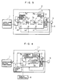
- FIG. 4 A specific example of the inverter is shown in Fig. 4.
- the reference numeral 3e designates an inverter control portion for controlling output voltage and frequency, 9 an AC motor and 11 an inverter apparatus.
- Like numerals in each of the drawings refer to like parts.
- the inverter is operated on the basis of a control signal from the outside to perform the operation of the induction motor in a predetermined pattern.
- a command signal generation portion 3a is provided in the inside of the apparatus. Accordingly, the inverter can be operated individually without any position command P* and any speed command N* issued from the external driving commander apparatus 1. Accordingly, function check and performance check can be made easily to attain an improvement in reliability.
- Fig. 5 shows an embodiment in which the parts 3c and 3d in Fig. 1 are replaced by a vector control portion 3h.
- the vector control is known so commonly that detailed description thereof can be omitted.
- Fig. 6 shows internal block construction in this embodiment
- Fig. 7 shows external appearance in this embodiment
- the reference numeral 8 designates a remote operation device having a on-line multi-bit display unit 8a.
- the remote operation device 8 serves to directly take in data, such as a position command P*, a speed command N*, and the like, given to the micro-computer 3 from the external driving commander apparatus 1, give a meaning to the "row", and "column", of the data and display the data.
- the micro-computer has a predetermined communication function corresponding to the remote operation device 8, so that the data given from the outside and taken in the micro-computer 3 can be transmitted back to the remote operation device 8.
- the servo controller 2 may be replaced by an inverter so that data given to the inverter from the driving commander apparatus 1 can be displayed in the display unit 8a of the remote operation device 8. Also in this case, function check, inclusive of the check of an interface to the external apparatus, can be made to attain a sufficient improvement in reliability.
- the display unit 8a of the remote operation device 8 is, in general, used at the time of generation of programs by means of the remote operation device 8. Accordingly, the display unit 8a is not always optimum for displaying data. In this case, therefore, an exclusive-use display unit may be further provided for the purpose of displaying data.
- the test operation of the motor driving control apparatus can be carried out individually and desiredly even before the apparatus is installed in a system. Accordingly, both function check and performance check can be made easily to attain a sufficient improvement in reliability and handling property.
Abstract
Description
- The present invention relates to an apparatus for driving an electric motor according to a control command supplied from an external apparatus such as an external computer or the like so as to control at least one of the rotational position and rotational speed of the motor, and particularly relates to a motor driving control apparatus suitable for the driving control of a servomotor used in robots and various kind of numerically controlled machine tools.
- In general, in order to drive a servomotor used in robots and various kinds of machine tools, driving power is supplied to the motor through a servo amplifier and the result is fed back by means of an encoder so that motor control exactly corresponding to a control command given from the outside can be attained. An example of this type motor driving control apparatus can be found in Japanese Patent Inexamined Publication JP-A-62-193585.
- In such a motor driving control apparatus, the control apparatus does not operate if no control command is supplied from the outside. In short, the motor cannot be driven with no control command.
- Accordingly, it is difficult for the apparatus per se to judge whether or not the function thereof is kept normal.
- In the above prior art, a test operation based on a feedback control pulse signal can be made. However, the prior art has no special consideration in making checking possible as to whether or not the function is kept normal with respect to the control command given from the outside. There arises therefore a problem in complete function maintenance check of the apparatus which has been not yet installed in a robot, a machine tool or the like.
- An object of the present invention is to provide a motor driving control apparatus in which the motor driving control apparatus as well as a motor can be checked whether they are in a perfect state before they are installed in a system such as a robot, a machine tool, or the like.
- To attain the foregoing object, the motor driving apparatus according to the present invention comprises: an internal control command generation means for generating a control command of a predetermined pattern to operate the motor; and a control command selection means for desiredly selecting one of an externally supplied control command and the control command supplied from the internal control command generation means to thereby control motor.
- According to the present invention, the control command selection means is operated so as to select a control command from the internal control command generation means so that the motor driving control apparatus can obtain a control command necessary for individually controlling the driving of the motor. Accordingly, the same operation as that in the case where a control command is supplied from the outside can be obtained, so that function check can be made easily.
- Other features and advantages of the present invention will be apparent from the following description taken in connection with the accompanying drawings, wherein:
- Fig. 1 is a block diagram showing a first embodiment of the motor driving control apparatus according to the present invention;
- Fig. 2 is a flow chart showing the details of a controlling processing;
- Fig. 3 is a block diagram showing a second embodiment of the present invention;
- Fig. 4 is a block diagram showing a third embodiment of the present invention;
- Fig. 5 is a block diagram showing a fourth embodiment of the present invention;
- Fig. 6 is a block diagram showing a fifth embodiment of the present invention; and
- Fig. 7 is a view of external appearance showing the relation of connection in the fifth embodiment of the present invention.
- The motor driving control apparatus according to the present invention will be described hereunder more in detail with respect to the embodiments illustrated in the drawings.
- Fig. 1 shows an embodiment in which the present invention is applied to a servomotor driving control apparatus which is used in a robot, a numerically controlled machine tool, or the like. In Fig. 1, the reference numeral 1 designates a driving commander apparatus which is in a rank higher than the motor driving control apparatus. The driving commander apparatus 1 is constituted by a control computer, a programmable controller, a data setter for setting various kinds of data, a pulse-train generator, and so on.
- The
reference numeral 2 designates a servo-controller, 3 a micro-computer (one-chip micro-computer) constituting theservo controller 2, 4 a current detector, 5 a servomotor, 6 an encoder and 7 a changeover switch. - In the micro-computer 3, incorporated are functions, in the form of software, necessary for the servo controller, such as an automatic position
control amplifier portion 3b, an automatic speedcontrol amplifier portion 3c, an automatic currentcontrol amplifier portion 3d, etc. In the micro-computer 3, further incorporated, also in the form of software, are a commandsignal generation portion 3a and astate monitor portion 3g. Of course, though not shown, storage means such as a ROM, a RAM and the like are provided in the micro-computer 3. - The
current detector 4 serves to detect a value of current supplied to the servomotor 5 from the automatic currentcontrol amplifier portion 3d to thereby output the current value as a current feedback signal IF. - The encoder 6 serves to detect the rotational position, the rotational speed and the like, of the servomotor 5 to thereby outputs them as a position feedback signal PF and a rotational speed feedback signal NF.
- The
reference numeral 3f designates a switch constituted by a software function, such as for exmaple an input port switching function, of the micro-computer 3. Theswitch 3f serves to select desired one, as a position command P* of the micro-computer 3, of the signal supplied from the external driving commander apparatus 1 and the signal supplied from the internal commandsignal generation portion 3a. Theswitch 3f is controlled by input operation by a human operator through a remote operation device 8 (which will be described later in detail). - As shown in the embodiment of Fig. 5, a
changeover switch 7 constituted by a snap switch or the like directly operated by a human operator may be provided to have a hardware function for switching the pattern of position command P*. Thereference numeral 10 designates a power amplifier section. - In the following, the operation of the apparatus in this embodiment is described.
- The operation of the motor driving control apparatus installed in a robot, a numerically controlled machine tool or the like after the switching position of the
changeover switch 7 has been set to the external driving commander apparatus 1 is the same as that of the conventional apparatus. That is, the apparatus is operated according to a position command P* given from the driving commander apparatus 1, so that a speed command N* is generated in the automatic positioncontrol amplifier portion 3b. The speed command N* is fed to the automatic speedcontrol amplifier portion 3c to form a current command I* to be fed to the automatic currentcontrol amplifier portion 3d. At this time, the current supplied to the servomotor 5 and the rotational position and rotational speed given by the servomotor 5 are fed back as feedback signals IF, PF and NF, respectively. Accordingly, exact control of the servomotor 5 in accordance with the position command P* supplied from the driving commander apparatus 1 is secured. - In the case where function check is required as to whether all functions of the motor driving control apparatus are maintained or in the case where performance check is required before the apparatus is installed in a robot, a machine tool or the like, the
switching portion 3f is operated to the position for inputting the signal from the internal commandsignal generation portion 3a. - At this time, the position command P* generated from the command
signal generation portion 3a is fed to the automatic positioncontrol amplifier portion 3b, so that the servomotor 5 can be operated individually by the motor driving control apparatus and in the operation form suitable to function check or performance check. Accordingly, function check or performance check can be made suitably and easily before the apparatus is installed in a robot, an NC machine tool or the like. Accordingly, failure, lowering of reliability, and the like, can be prevented from occurring. - As described above, the command
signal generation portion 3a is designed so as to generate a test-operation position command P* (or a speed command N*) of a predetermined pattern useful for function check or performance check of the whole of the motor driving control apparatus including the servomotor 5 by software processing of the micro-computer 3. Therefore, a program necessary for generating this pattern is stored in the micro-computer 3 in advance, so that the position command P* of this pattern is issued automatically. Further, a function for inputting programs through the remote operation device and a memory function necessary for storing the programs may be provided to generate and store this pattern suitably by a user or the like. - An embodiment of processing, executed by the micro-computer 3, suitable for the aforementioned operation, will be described below with reference to Fig. 2.
- When processing starts, a judgment is made in Step 1 as to whether or not test operation is designated. The judgment can be made by examining the switching position of the
changeover switch 7. - When, for example, the
changeover switch 7 is in the position to select the external driving commander apparatus, the situation of the processing is shifted to the execution of ordinary operation. - Thereafter, the operation of a predetermined pattern is carried out according to the position command P* generated from the command
signal generation portion 3a. When it is confirmed that the operation of this pattern is attained perfectly, the test operation is terminated. Occurrence of a trip (abnormal cutoff) is always monitored during the test operation so that a trip processing can be carried out preferentially. - After the test operation is terminated, the current supplied to the servomotor 5 may be cut off soon or the state of current supply may be fixed after the movement of the servomotor 5 to the designated stop position so that operation check can be made in a so-called servo-lock state.
- Further, the apparatus may be designed to be suitable for the individual test operation of only the
servo controller 2 without connecting the servomotor 5 to theservo controller 2. At this time, the judgment gas to whether the test operation of the servomotor is normal or not may be performed based on the detection of an abnormality of an output signal of the encoder 6. Alternatively, the judgment may be performed based on the failure of switching elements such as transistors in the motor driving circuit without performing the detection of the abnormality of the output signal of the encoder 6. - A test operation pattern suitable for giving accelerative and decelerative motion to the motor may be used. In this case, the current takes a maximum value (a limit value in a current control system) at each of the time of acceleration and the time of deceleration so that safety check can be made. It is a matter of course that the operation pattern may be provided so as to be suitable for performance check of the apparatus. The judgment as to whether the operation state is normal is made in the
state monitor portion 3g in Fig. 1. - Although the aforementioned embodiment has shown the case where the present invention is applied to a servomotor driving control apparatus, it is to be understood that the present invention may be applied to an inverter for driving an induction motor. In this case, the inverter corresponds to the
servo controller 2 in Fig. 1. - A specific example of the inverter is shown in Fig. 4. In Fig. 4, the
reference numeral 3e designates an inverter control portion for controlling output voltage and frequency, 9 an AC motor and 11 an inverter apparatus. Like numerals in each of the drawings refer to like parts. - In general, the inverter is operated on the basis of a control signal from the outside to perform the operation of the induction motor in a predetermined pattern. In this embodiment, a command
signal generation portion 3a is provided in the inside of the apparatus. Accordingly, the inverter can be operated individually without any position command P* and any speed command N* issued from the external driving commander apparatus 1. Accordingly, function check and performance check can be made easily to attain an improvement in reliability. - Fig. 5 shows an embodiment in which the
parts - A further embodiment will be described below with reference to Figs. 6 and 7.
- Fig. 6 shows internal block construction in this embodiment, and Fig. 7 shows external appearance in this embodiment. In Figs. 6 and 7, the
reference numeral 8 designates a remote operation device having a on-linemulti-bit display unit 8a. Theremote operation device 8 serves to directly take in data, such as a position command P*, a speed command N*, and the like, given to themicro-computer 3 from the external driving commander apparatus 1, give a meaning to the "row", and "column", of the data and display the data. - On the other hand, in this embodiment, the micro-computer has a predetermined communication function corresponding to the
remote operation device 8, so that the data given from the outside and taken in themicro-computer 3 can be transmitted back to theremote operation device 8. - In this embodiment, accordingly, data given from the outside can be confirmed bit by bit with eyes, so that the external data and the interface for inputting the external data can be checked to attain a greater improvement in reliability.
- In this embodiment, at that time, data are displayed and monitored by using the
display unit 8a provided in theremote operation device 8 which is included in the motor driving control apparatus. Accordingly, there is little fear of increase in cost. - Although the aforementioned embodiment also has shown the case where the present invention is applied to a servomotor driving control apparatus, it is to be understood that the present invention may be applied to an inverter for driving an induction motor.
- In short, the
servo controller 2 may be replaced by an inverter so that data given to the inverter from the driving commander apparatus 1 can be displayed in thedisplay unit 8a of theremote operation device 8. Also in this case, function check, inclusive of the check of an interface to the external apparatus, can be made to attain a sufficient improvement in reliability. - In the embodiment as shown in Figs. 6 and 7, the
display unit 8a of theremote operation device 8 is, in general, used at the time of generation of programs by means of theremote operation device 8. Accordingly, thedisplay unit 8a is not always optimum for displaying data. In this case, therefore, an exclusive-use display unit may be further provided for the purpose of displaying data. - According to the present invention, the test operation of the motor driving control apparatus can be carried out individually and desiredly even before the apparatus is installed in a system. Accordingly, both function check and performance check can be made easily to attain a sufficient improvement in reliability and handling property.
Claims (15)
an internal control command generation means (3a) for generating a control command of a predetermined pattern to operate said motor; and
a control command selection means (3f) for selecting desired one of the control command given from said external apparatus and the control command given from said internal control command generation means so that the selected control command is made to be a control command for said motor.
making a judgment as to whether the operation mode to be executed is an external control command operation mode or a test operation mode;
performing a test operation according to a command given from an internal command signal generation portion (3a), when said judgment proves that the operation mode is the test operation mode; and
ascertaining whether the executed test operation accords with said command.
an internal control command generation means (3a) for generating a control command of a predetermined pattern to operate said motor;
a control command selection means (3f) for desiredly selecting one of the control command given from said external apparatus and the control command given from said internal control command generation means, based on a command signal from said change-over commander section to control said motor;
an automatic position control portion (3b);
an automatic speed control portion (3c);
an automatic current control portion (3d);
and
an operation analysis means (3g) for analyzing the contents of a controlling operation at the time of the individual controlling operation in accordance with the control command given from said internal control command generation means.
an internal control command generation means (3a) for generating a control command of a predetermined pattern to operate said motor;
an automatic position control portion (3b);
an automatic speed control portion (3c);
an automatic current control portion (3d); and
an operation analysis means (3g) for analyzing the contents of a controlling operation at the time of the individual controlling operation in accordance with the control command given from said internal control command generation means.
an internal control command generation means (3a) for generating a control command of a predetermined pattern to operate said motor;
a control command selection means (3f) for selecting desired one of the control command given from said external apparatus and the control command given from said internal control command generation means, based on a command signal from said switching commander section to control said motor;
an automatic position control portion (3b); a vector control arithmetic operation portion (3h); and
an operation analysis means (3g) for analyzing the contents of a controlling operation at the time of the individual controlling operation in accordance with the control command given from said internal control command generation means.
Applications Claiming Priority (3)
| Application Number | Priority Date | Filing Date | Title |
|---|---|---|---|
| JP303171/89 | 1989-11-24 | ||
| JP30317189 | 1989-11-24 | ||
| JP1303171A JP2954615B2 (en) | 1989-11-24 | 1989-11-24 | Motor drive control device |
Publications (3)
| Publication Number | Publication Date |
|---|---|
| EP0428950A2 true EP0428950A2 (en) | 1991-05-29 |
| EP0428950A3 EP0428950A3 (en) | 1993-09-22 |
| EP0428950B1 EP0428950B1 (en) | 1999-06-16 |
Family
ID=17917744
Family Applications (1)
| Application Number | Title | Priority Date | Filing Date |
|---|---|---|---|
| EP90121509A Expired - Lifetime EP0428950B1 (en) | 1989-11-24 | 1990-11-09 | Motor driving control apparatus |
Country Status (5)
| Country | Link |
|---|---|
| US (1) | US5200678A (en) |
| EP (1) | EP0428950B1 (en) |
| JP (1) | JP2954615B2 (en) |
| KR (1) | KR930010165B1 (en) |
| DE (1) | DE69033164T2 (en) |
Cited By (1)
| Publication number | Priority date | Publication date | Assignee | Title |
|---|---|---|---|---|
| KR20150134323A (en) * | 2013-03-29 | 2015-12-01 | 파나소닉 아이피 매니지먼트 가부시키가이샤 | Servo adjustment method for motor drive device |
Families Citing this family (10)
| Publication number | Priority date | Publication date | Assignee | Title |
|---|---|---|---|---|
| JP3309828B2 (en) * | 1999-04-22 | 2002-07-29 | 日本精工株式会社 | Motor drive control device |
| JP2000006070A (en) * | 1998-06-19 | 2000-01-11 | Fanuc Ltd | Robot control system |
| KR100357433B1 (en) * | 2000-08-18 | 2002-10-19 | 이모션텍 주식회사 | drive control method for addition and substruction of motor |
| TWM307115U (en) * | 2006-09-29 | 2007-03-01 | Princeton Technology Corp | Apparatus for testing integrated circuit |
| JP5273582B2 (en) * | 2008-02-20 | 2013-08-28 | 日本精工株式会社 | Servo motor control method |
| EP2103461B1 (en) * | 2008-03-18 | 2012-10-10 | Mazda Motor Corporation | Induction heating system for a motor-driven vehicle |
| DE102014016852B4 (en) | 2013-11-22 | 2017-06-08 | HKR Seuffer Automotive GmbH & Co. KG | Control system for an electric motor based on a pulsed control signal |
| CN105159205B (en) * | 2015-10-16 | 2018-04-20 | 东莞市海川数控技术有限公司 | High speed position applied to motion controller catches implementation method and device |
| DE102017112817A1 (en) * | 2017-06-12 | 2018-12-13 | Dr. Ing. H.C. F. Porsche Aktiengesellschaft | Commissioning control unit of a composite of control units of a motor vehicle and method for commissioning of control units |
| LU101274B1 (en) * | 2019-06-17 | 2020-12-18 | Phoenix Contact Gmbh & Co | Automatic monitoring of process controls |
Citations (7)
| Publication number | Priority date | Publication date | Assignee | Title |
|---|---|---|---|---|
| JPS55150012A (en) * | 1979-05-11 | 1980-11-21 | Hitachi Ltd | Test unit |
| JPS56149614A (en) * | 1980-04-21 | 1981-11-19 | Komatsu Ltd | Self-diagnosis method of nc device |
| EP0115543A1 (en) * | 1982-08-05 | 1984-08-15 | Fanuc Ltd. | Function diagnosis system |
| JPS6122281A (en) * | 1985-07-03 | 1986-01-30 | Tokyo Optical Co Ltd | Optical distance measuring device having self-checking function |
| FR2580091A1 (en) * | 1985-04-04 | 1986-10-10 | Canon Kk | |
| WO1987004276A1 (en) * | 1985-12-30 | 1987-07-16 | Arends Gregory E | Motor system |
| WO1990002981A1 (en) * | 1988-09-02 | 1990-03-22 | Fanuc Ltd | System for diagnosing cnc |
Family Cites Families (10)
| Publication number | Priority date | Publication date | Assignee | Title |
|---|---|---|---|---|
| US4109185A (en) * | 1976-12-27 | 1978-08-22 | Mcdonnell Douglas Corporation | Servo system employing digital components |
| JPS5653588A (en) * | 1979-10-09 | 1981-05-13 | Fanuc Ltd | Main shaft rotation control system |
| US4445184A (en) * | 1980-07-19 | 1984-04-24 | Shin Meiwa Industry Co., Ltd. | Articulated robot |
| CH639584A5 (en) * | 1980-10-10 | 1983-11-30 | Microbo Sa | AUTOMATED SUSCEPTIBLE TEACHER. |
| US4422040A (en) * | 1981-11-05 | 1983-12-20 | International Business Machines Corporation | Method of testing stepping motors |
| JPS6018237A (en) * | 1983-07-08 | 1985-01-30 | Komatsu Ltd | Control circuit of transfer device |
| JPS6318403A (en) * | 1986-07-10 | 1988-01-26 | Fanuc Ltd | Off-line control executing method |
| US4843292A (en) * | 1987-03-02 | 1989-06-27 | Yokogawa Electric Corporation | Direct drive motor system |
| FR2612645B1 (en) * | 1987-03-20 | 1989-05-19 | Bendix France | METHOD AND DEVICE FOR VERIFYING THE OPERATING STATE OF A MAGNETIC SENSOR WITH VARIABLE RELUCTANCE AND THEIR APPLICATION IN AUTOMOTIVE ELECTRONICS |
| AU602996B2 (en) * | 1987-10-23 | 1990-11-01 | Mitsubishi Jukogyo Kabushiki Kaisha | Control systems of an industrial robot |
-
1989
- 1989-11-24 JP JP1303171A patent/JP2954615B2/en not_active Expired - Lifetime
-
1990
- 1990-10-22 KR KR1019900016844A patent/KR930010165B1/en not_active IP Right Cessation
- 1990-11-06 US US07/609,660 patent/US5200678A/en not_active Expired - Lifetime
- 1990-11-09 EP EP90121509A patent/EP0428950B1/en not_active Expired - Lifetime
- 1990-11-09 DE DE69033164T patent/DE69033164T2/en not_active Expired - Lifetime
Patent Citations (7)
| Publication number | Priority date | Publication date | Assignee | Title |
|---|---|---|---|---|
| JPS55150012A (en) * | 1979-05-11 | 1980-11-21 | Hitachi Ltd | Test unit |
| JPS56149614A (en) * | 1980-04-21 | 1981-11-19 | Komatsu Ltd | Self-diagnosis method of nc device |
| EP0115543A1 (en) * | 1982-08-05 | 1984-08-15 | Fanuc Ltd. | Function diagnosis system |
| FR2580091A1 (en) * | 1985-04-04 | 1986-10-10 | Canon Kk | |
| JPS6122281A (en) * | 1985-07-03 | 1986-01-30 | Tokyo Optical Co Ltd | Optical distance measuring device having self-checking function |
| WO1987004276A1 (en) * | 1985-12-30 | 1987-07-16 | Arends Gregory E | Motor system |
| WO1990002981A1 (en) * | 1988-09-02 | 1990-03-22 | Fanuc Ltd | System for diagnosing cnc |
Non-Patent Citations (2)
| Title |
|---|
| PATENT ABSTRACTS OF JAPAN vol. 10, no. 173 (P-469)18 June 1986 & JP-A-61 022 281 ( TOUKIYOU KOUGAKU ) 30 January 1986 * |
| PATENT ABSTRACTS OF JAPAN vol. 6, no. 30 (P-103)(908) 23 February 1982 & JP-A-56 149 614 ( KOMATSU ) 19 November 1981 * |
Cited By (2)
| Publication number | Priority date | Publication date | Assignee | Title |
|---|---|---|---|---|
| KR20150134323A (en) * | 2013-03-29 | 2015-12-01 | 파나소닉 아이피 매니지먼트 가부시키가이샤 | Servo adjustment method for motor drive device |
| EP2980986A4 (en) * | 2013-03-29 | 2016-08-17 | Panasonic Ip Man Co Ltd | Servo adjustment method for motor drive device |
Also Published As
| Publication number | Publication date |
|---|---|
| US5200678A (en) | 1993-04-06 |
| JP2954615B2 (en) | 1999-09-27 |
| KR930010165B1 (en) | 1993-10-15 |
| EP0428950B1 (en) | 1999-06-16 |
| JPH03169284A (en) | 1991-07-22 |
| DE69033164T2 (en) | 2000-02-24 |
| KR910010816A (en) | 1991-06-29 |
| DE69033164D1 (en) | 1999-07-22 |
| EP0428950A3 (en) | 1993-09-22 |
Similar Documents
| Publication | Publication Date | Title |
|---|---|---|
| CN108693791B (en) | Component mounting position guide device, component mounting position guide system and method | |
| US7203568B2 (en) | Numerical controller | |
| CN105320064B (en) | Numerical controller having function of assisting analysis of equipment abnormality history | |
| EP0962281B1 (en) | Industrial machine having abnormal vibration detecting function | |
| US5200678A (en) | Motor driving control apparatus | |
| WO1995004633A1 (en) | Tool life estimation method | |
| EP0397887B1 (en) | Method of correcting machining program | |
| US6897626B2 (en) | Synchronous controller | |
| EP1826644A2 (en) | Numerical controller | |
| EP0511395A1 (en) | Conversational type numerical control equipment | |
| US4862379A (en) | Numerical control machine | |
| US5337249A (en) | Numerical control machining animation with workpiece and tool movement | |
| JP2762788B2 (en) | Moving body operation display device and display method thereof | |
| JPH08263113A (en) | Abnormality processing control unit | |
| US5191538A (en) | Apparatus for displaying operation sequence of numerically controlled machine tool | |
| JPH04235610A (en) | Abnormality detector for industrial robot | |
| US6397123B1 (en) | Numerical control apparatus | |
| EP0919894B1 (en) | Controller for industrial machine | |
| US20050144205A1 (en) | Waveform display apparatus | |
| JPH0976144A (en) | Machining state monitoring method in machine tool | |
| CN110351517B (en) | Visual guidance device, visual guidance system, and visual guidance method | |
| JP2753320B2 (en) | Numerical control unit | |
| JP2559273B2 (en) | Numerical control device and screen display method of numerical control device | |
| JPH09141539A (en) | Display device for industrial machine | |
| WO2023203724A1 (en) | Display device, and computer-readable storage medium |
Legal Events
| Date | Code | Title | Description |
|---|---|---|---|
| PUAI | Public reference made under article 153(3) epc to a published international application that has entered the european phase |
Free format text: ORIGINAL CODE: 0009012 |
|
| 17P | Request for examination filed |
Effective date: 19901127 |
|
| AK | Designated contracting states |
Kind code of ref document: A2 Designated state(s): DE FR GB |
|
| PUAL | Search report despatched |
Free format text: ORIGINAL CODE: 0009013 |
|
| AK | Designated contracting states |
Kind code of ref document: A3 Designated state(s): DE FR GB |
|
| 17Q | First examination report despatched |
Effective date: 19951201 |
|
| GRAG | Despatch of communication of intention to grant |
Free format text: ORIGINAL CODE: EPIDOS AGRA |
|
| GRAG | Despatch of communication of intention to grant |
Free format text: ORIGINAL CODE: EPIDOS AGRA |
|
| GRAG | Despatch of communication of intention to grant |
Free format text: ORIGINAL CODE: EPIDOS AGRA |
|
| GRAH | Despatch of communication of intention to grant a patent |
Free format text: ORIGINAL CODE: EPIDOS IGRA |
|
| GRAH | Despatch of communication of intention to grant a patent |
Free format text: ORIGINAL CODE: EPIDOS IGRA |
|
| GRAA | (expected) grant |
Free format text: ORIGINAL CODE: 0009210 |
|
| AK | Designated contracting states |
Kind code of ref document: B1 Designated state(s): DE FR GB |
|
| REF | Corresponds to: |
Ref document number: 69033164 Country of ref document: DE Date of ref document: 19990722 |
|
| ET | Fr: translation filed | ||
| PLBE | No opposition filed within time limit |
Free format text: ORIGINAL CODE: 0009261 |
|
| STAA | Information on the status of an ep patent application or granted ep patent |
Free format text: STATUS: NO OPPOSITION FILED WITHIN TIME LIMIT |
|
| 26N | No opposition filed | ||
| REG | Reference to a national code |
Ref country code: GB Ref legal event code: IF02 |
|
| PGFP | Annual fee paid to national office [announced via postgrant information from national office to epo] |
Ref country code: DE Payment date: 20091123 Year of fee payment: 20 |
|
| PGFP | Annual fee paid to national office [announced via postgrant information from national office to epo] |
Ref country code: GB Payment date: 20091023 Year of fee payment: 20 Ref country code: FR Payment date: 20091103 Year of fee payment: 20 |
|
| REG | Reference to a national code |
Ref country code: GB Ref legal event code: PE20 Expiry date: 20101108 |
|
| PG25 | Lapsed in a contracting state [announced via postgrant information from national office to epo] |
Ref country code: GB Free format text: LAPSE BECAUSE OF EXPIRATION OF PROTECTION Effective date: 20101108 |
|
| PG25 | Lapsed in a contracting state [announced via postgrant information from national office to epo] |
Ref country code: DE Free format text: LAPSE BECAUSE OF EXPIRATION OF PROTECTION Effective date: 20101109 |