WO2022239274A1 - 光学系、画像投写装置および撮像装置 - Google Patents
光学系、画像投写装置および撮像装置 Download PDFInfo
- Publication number
- WO2022239274A1 WO2022239274A1 PCT/JP2021/043684 JP2021043684W WO2022239274A1 WO 2022239274 A1 WO2022239274 A1 WO 2022239274A1 JP 2021043684 W JP2021043684 W JP 2021043684W WO 2022239274 A1 WO2022239274 A1 WO 2022239274A1
- Authority
- WO
- WIPO (PCT)
- Prior art keywords
- lens group
- optical system
- lens
- lens element
- positive
- Prior art date
- Legal status (The legal status is an assumption and is not a legal conclusion. Google has not performed a legal analysis and makes no representation as to the accuracy of the status listed.)
- Ceased
Links
Images






Classifications
-
- G—PHYSICS
- G02—OPTICS
- G02B—OPTICAL ELEMENTS, SYSTEMS OR APPARATUS
- G02B15/00—Optical objectives with means for varying the magnification
- G02B15/14—Optical objectives with means for varying the magnification by axial movement of one or more lenses or groups of lenses relative to the image plane for continuously varying the equivalent focal length of the objective
- G02B15/143—Optical objectives with means for varying the magnification by axial movement of one or more lenses or groups of lenses relative to the image plane for continuously varying the equivalent focal length of the objective having three groups only
- G02B15/1431—Optical objectives with means for varying the magnification by axial movement of one or more lenses or groups of lenses relative to the image plane for continuously varying the equivalent focal length of the objective having three groups only the first group being positive
- G02B15/143103—Optical objectives with means for varying the magnification by axial movement of one or more lenses or groups of lenses relative to the image plane for continuously varying the equivalent focal length of the objective having three groups only the first group being positive arranged ++-
-
- G—PHYSICS
- G02—OPTICS
- G02B—OPTICAL ELEMENTS, SYSTEMS OR APPARATUS
- G02B13/00—Optical objectives specially designed for the purposes specified below
- G02B13/04—Reversed telephoto objectives
-
- G—PHYSICS
- G02—OPTICS
- G02B—OPTICAL ELEMENTS, SYSTEMS OR APPARATUS
- G02B13/00—Optical objectives specially designed for the purposes specified below
- G02B13/0095—Relay lenses or rod lenses
-
- G—PHYSICS
- G02—OPTICS
- G02B—OPTICAL ELEMENTS, SYSTEMS OR APPARATUS
- G02B13/00—Optical objectives specially designed for the purposes specified below
- G02B13/16—Optical objectives specially designed for the purposes specified below for use in conjunction with image converters or intensifiers, or for use with projectors, e.g. objectives for projection TV
-
- G—PHYSICS
- G02—OPTICS
- G02B—OPTICAL ELEMENTS, SYSTEMS OR APPARATUS
- G02B15/00—Optical objectives with means for varying the magnification
- G02B15/14—Optical objectives with means for varying the magnification by axial movement of one or more lenses or groups of lenses relative to the image plane for continuously varying the equivalent focal length of the objective
- G02B15/144—Optical objectives with means for varying the magnification by axial movement of one or more lenses or groups of lenses relative to the image plane for continuously varying the equivalent focal length of the objective having four groups only
- G02B15/1441—Optical objectives with means for varying the magnification by axial movement of one or more lenses or groups of lenses relative to the image plane for continuously varying the equivalent focal length of the objective having four groups only the first group being positive
- G02B15/144111—Optical objectives with means for varying the magnification by axial movement of one or more lenses or groups of lenses relative to the image plane for continuously varying the equivalent focal length of the objective having four groups only the first group being positive arranged ++-+
-
- G—PHYSICS
- G02—OPTICS
- G02B—OPTICAL ELEMENTS, SYSTEMS OR APPARATUS
- G02B15/00—Optical objectives with means for varying the magnification
- G02B15/14—Optical objectives with means for varying the magnification by axial movement of one or more lenses or groups of lenses relative to the image plane for continuously varying the equivalent focal length of the objective
- G02B15/16—Optical objectives with means for varying the magnification by axial movement of one or more lenses or groups of lenses relative to the image plane for continuously varying the equivalent focal length of the objective with interdependent non-linearly related movements between one lens or lens group, and another lens or lens group
- G02B15/20—Optical objectives with means for varying the magnification by axial movement of one or more lenses or groups of lenses relative to the image plane for continuously varying the equivalent focal length of the objective with interdependent non-linearly related movements between one lens or lens group, and another lens or lens group having an additional movable lens or lens group for varying the objective focal length
-
- G—PHYSICS
- G02—OPTICS
- G02B—OPTICAL ELEMENTS, SYSTEMS OR APPARATUS
- G02B13/00—Optical objectives specially designed for the purposes specified below
- G02B13/18—Optical objectives specially designed for the purposes specified below with lenses having one or more non-spherical faces, e.g. for reducing geometrical aberration
Definitions
- the present disclosure relates to an optical system that forms an intermediate image.
- the present disclosure also relates to an image projection device and an imaging device using such an optical system.
- the intermediate imaging optical system has the advantage of being able to achieve wide-angle projection on a large screen with a short focus.
- the wider the angle the greater the variation in aberrations such as curvature of field and astigmatism when performing focus adjustment in accordance with the object distance, possibly degrading optical performance.
- Patent document 1 discloses a wide-angle imaging optical system, and focus adjustment is performed by two focus groups on the enlargement side of intermediate imaging. Therefore, in this imaging optical system, the center of gravity is on the enlargement side of the optical system due to the driving member including the actuator that constitutes the focus group. Further, in this imaging optical system, the off-axis curvature of field fluctuates by about 0.05 mm during focusing.
- Patent Document 2 discloses a wide-angle imaging optical system, and performs focus adjustment with two or three focus groups.
- the meridional field curvature change of 0.1 mm or more occurs between the closest side and the far side off the axis, and the optical performance is insufficient.
- the meridional field curvature change between the closest side and the far side off the axis is small, and the optical characteristics are good. weight increases.
- the present disclosure provides an optical system in which focus adjustment is easy and in which the size and weight of the focus mechanism can be reduced.
- the present disclosure also provides an image projection device and an imaging device using such an optical system.
- An optical system is an optical system that internally includes an intermediate imaging position that is conjugate with an expansion conjugate point on the expansion side and a reduction conjugate point on the reduction side, a first positive lens group having a plurality of lens elements and positioned on the enlargement side of the intermediate imaging position; a second positive lens group having a plurality of lens elements and positioned between the first positive lens group and the intermediate imaging position; a negative lens group having a plurality of lens elements and positioned on the reduction side of the intermediate imaging position; During focusing, the first positive lens group and the negative lens group move along the optical axis, and the second positive lens group remains stationary.
- An image projection apparatus includes the optical system and an image forming element that generates an image to be projected onto a screen via the optical system.
- An imaging device includes the optical system described above and an imaging device that receives an optical image formed by the optical system and converts the optical image into an electrical image signal.
- focus adjustment is easy, and the size and weight of the focus mechanism can be reduced.
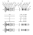
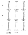
- Layout of the wide-angle end of the zoom lens system of Example 1 at an object distance of 1080 mm Longitudinal aberration diagram of the zoom lens system of Example 1 at an object distance of 1080 mm
- the optical system is a projector (image projection system) that projects onto a screen image light of an original image S obtained by spatially modulating incident light by an image forming element such as a liquid crystal or a DMD (digital micromirror device) based on an image signal.
- an image forming element such as a liquid crystal or a DMD (digital micromirror device)
- An example of a device will be described. That is, the optical system according to the present disclosure can be used to arrange a screen (not shown) on the extension of the enlargement side, and to enlarge and project the original image S on the image forming element arranged on the reduction side onto the screen.
- the optical system according to the present disclosure collects light emitted from an object positioned on an extension line on the enlargement side, and forms an optical image of the object on the imaging surface of the imaging device arranged on the reduction side. is also available.
- Embodiment 1 of the present disclosure will be described below with reference to FIGS. 1 to 25.
- FIG. Here, a zoom lens system will be described as an example of an optical system.
- 1, 6, 11, 16, and 21 are layout diagrams showing optical paths at the wide-angle end at an object distance of 1080 mm in the zoom lens systems according to Examples 1-5.
- 2, 7, 12, 17, and 22 are layout diagrams of the wide-angle end at the object distance of 1080 mm of the zoom lens systems according to Examples 1-5.
- FIGS. 2(a), 7(a), 12(a), 17(a), and 22(a) show lens layout diagrams at the wide-angle end of the zoom lens system.
- FIGS. 2(b), 7(b), 12(b), 17(b), and 22(b) show lens layout diagrams at intermediate positions of the zoom lens system.
- FIGS. 2(c), 7(c), 12(c), 17(c), and 22(c) show lens layout diagrams at the telephoto end of the zoom lens system.
- the wide-angle end is the shortest focal length state in which the entire system has the shortest focal length fw.
- An intermediate position is an intermediate focal length state between the wide-angle end and the telephoto end.
- the zoom lens systems according to Examples 1 to 5 internally have an intermediate imaging position MI that is conjugate with the enlargement conjugate point on the enlargement side and the reduction conjugate point on the reduction side.
- An enlarging optical system Op is arranged on the enlarging side of the intermediate imaging position MI, and a relay optical system Ol is arranged on the reducing side of the intermediate imaging position MI.
- An optical element P is arranged on the reduction side of the relay optical system Ol.
- the zoom lens systems according to Examples 1 to 5 include the first lens group G1 to the fourth lens group G4 that can move independently of each other.
- the first lens group G1 has a positive power, is composed of the first lens element L1 to the fifteenth lens element L15, and includes surfaces 1 to 30 (surface numbers refer to numerical examples described later). reference).
- the second lens group G2 has positive power, is composed of sixteenth lens element L16 to eighteenth lens element L18, and includes surfaces 31 to .
- the third lens group G3 has negative power, is composed of the 19th lens element L19 to the 22nd lens element L22, and includes surfaces 37 to 45.
- the fourth lens group G4 has positive power, is composed of the twenty-third lens element L23 to the twenty-fifth lens element L25, and includes surfaces 46 to 51.
- FIG. Optical element P includes surfaces 52-53.
- the polygonal arrows shown between each figure (a) and each figure (b) indicate, from top to bottom, the first lens group G1 to the fourth lens in each state of the wide-angle end, intermediate position, and telephoto end.
- a straight line obtained by connecting the positions of the group G4.
- the wide-angle end and the intermediate position, and the intermediate position and the telephoto end are simply connected by a straight line, which differs from the actual movements of the lens groups G1 to G4.
- the symbols (+) and (-) attached to the symbols of the lens groups G1 to G4 indicate positive and negative powers of the lens groups G1 to G4.
- the zoom lens systems according to Examples 1 to 5 have a focus lens group that performs focus adjustment when the object distance changes, and an image plane after the focus adjustment performed by the focus lens group.
- a field curvature correction lens group that corrects curvature aberration may also be included.
- the zoom lens systems according to Examples 1 to 5 include a first positive lens group GP1 having positive power, a second positive lens group GP2 having positive power, and a negative lens group GN having negative power. including.
- the first positive lens group GP1 and the negative lens group GN move independently of each other along the optical axis, while the second positive lens group GP2 remains stationary.
- the first positive lens group GP1 can function as the field curvature correction lens group described above
- the negative lens group GN can function as the focus lens group described above.
- the imaging position on the enlargement side (that is, the enlargement conjugate point) is located on the left side
- the imaging position on the reduction side (that is, the reduction conjugate point) is located on the right side.
- the straight line drawn on the side of the most reduction represents the position of the original image S
- the optical element P is positioned on the side of the enlargement of the original image S.
- the optical element P represents an optical element such as a prism for color separation and color synthesis, an optical filter, parallel plate glass, a crystal low-pass filter, and an infrared cut filter.
- 3, 8, 13, 18, and 23 are longitudinal aberration diagrams at an object distance of 1080 mm of the zoom lens systems according to Examples 1-5.
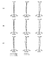
- 4, 9, 14, 19, and 24 are longitudinal aberration diagrams at an object distance 780 of the zoom lens systems according to Examples 1-5.
- 5, 10, 15, 20, and 25 are longitudinal aberration diagrams of the zoom lens systems according to Examples 1 to 5 at an object distance of 2900 mm.
- (a), (b), and (c) in each figure show longitudinal aberration diagrams at the wide-angle end, intermediate position, and telephoto end of the zoom lens system.
- Each longitudinal aberration diagram shows spherical aberration (SA (mm)), astigmatism (AST (mm)), and distortion (DIS (%)) in order from the left.
- the vertical axis represents the height of the pupil
- the solid line is the d-line
- the short dashed line is the F-line
- the long dashed line is the C-line.
- the vertical axis represents the image height
- the solid line is the sagittal plane (indicated by s in the figure)
- the broken line is the meridional plane (indicated by m in the figure).
- the vertical axis represents the image height.
- the distortion aberration represents the distortion aberration for equidistant projection.
- the zoom lens system according to Example 1 includes an enlarging optical system Op and a relay optical system Ol.
- the enlarging optical system Op is composed of the first lens element L1 to the twelfth lens element L12 in order from the enlarging side to the reducing side.
- the first lens element L1 has a negative meniscus shape with a convex surface facing the magnification side.
- the second lens element L2 has a positive meniscus shape with a convex surface facing the magnification side.
- the third lens element L3 has a negative meniscus shape with a convex surface facing the magnification side.
- the fourth lens element L4 has a negative meniscus shape with a convex surface facing the magnification side.
- the fifth lens element L5 has a biconvex shape.
- the sixth lens element L6 has a positive meniscus shape with a convex surface facing the reduction side.
- the seventh lens element L7 has a biconvex shape.
- the eighth lens element L8 has a biconcave shape.
- the ninth lens element L9 has a positive meniscus shape with a convex surface facing the reduction side.
- the tenth lens element L10 has a biconvex shape.
- the eleventh lens element L11 has a biconvex shape.
- the twelfth lens element L12 has a positive meniscus shape with a convex surface facing the magnification side.
- the relay optical system Ol is composed of the 13th lens element L13 to the 25th lens element L25 in order from the enlargement side to the reduction side.
- the thirteenth lens element L13 has a biconcave shape.
- the fourteenth lens element L14 has a biconcave shape.
- the fifteenth lens element L15 has a positive meniscus shape with a convex surface facing the reduction side.
- the sixteenth lens element L16 has a biconvex shape.
- the seventeenth lens element L17 has a biconcave shape.
- the eighteenth lens element L18 has a biconvex shape.
- the nineteenth lens element L19 has a positive meniscus shape with a convex surface facing the enlargement side.
- the twentieth lens element L20 has a negative meniscus shape with a convex surface facing the magnification side.
- the twenty-first lens element L21 has a negative meniscus shape with a convex surface facing the reduction side.
- the twenty-second lens element L22 has a biconvex shape.
- the twenty-third lens element L23 has a biconvex shape.
- the twenty-fourth lens element L24 has a negative meniscus shape with a convex surface facing the magnification side.
- the twenty-fifth lens element L25 has a biconvex shape.
- An intermediate imaging position MI between the twelfth lens element L12 and the thirteenth lens element L13.
- a diaphragm A is arranged between the nineteenth lens element L19 and the twentieth lens element L20.
- An optical element P whose optical power is zero is arranged on the reduction side of the relay optical system Ol.
- the first positive lens group GP1 is composed of the first lens element L1 to the ninth lens element L9.
- the second positive lens group GP2 is composed of a tenth lens element L10 to a twelfth lens element L12.
- the negative lens group GN is composed of the thirteenth lens element L13 to the fourteenth lens element L14.
- the zoom lens system according to Example 2 includes an enlarging optical system Op and a relay optical system Ol.
- the enlarging optical system Op is composed of the first lens element L1 to the twelfth lens element L12 in order from the enlarging side to the reducing side.
- the shapes of the first lens element L1 to the ninth lens element L9 and the twelfth lens element L12 are the same as those in Example 1, and redundant description will be omitted.
- the tenth lens element L10 has a positive meniscus shape with a convex surface facing the reduction side.
- the eleventh lens element L11 has a positive meniscus shape with a convex surface facing the enlargement side.
- the relay optical system Ol is composed of the 13th lens element L16 to the 25th lens element L25 in order from the enlargement side to the reduction side. These lens shapes are the same as those in Example 1, and redundant description is omitted. Arrangements of the intermediate imaging position MI, the diaphragm A and the optical element P are also the same as in the first embodiment.
- the first positive lens group GP1 is composed of the first lens element L1 to the ninth lens element L9.
- the second positive lens group GP2 is composed of a tenth lens element L10 to a twelfth lens element L12.
- the negative lens group GN is composed of the thirteenth lens element L13 to the fourteenth lens element L14.
- the zoom lens system according to Example 3 includes an enlarging optical system Op and a relay optical system Ol.
- the enlarging optical system Op is composed of the first lens element L1 to the twelfth lens element L12 in order from the enlarging side to the reducing side.
- the relay optical system Ol is composed of the 13th lens element L16 to the 25th lens element L25 in order from the enlargement side to the reduction side.
- the first positive lens group GP1 is composed of the first lens element L1 to the ninth lens element L9.
- the second positive lens group GP2 is composed of a tenth lens element L10 to a twelfth lens element L12.
- the negative lens group GN is composed of the thirteenth lens element L13 to the fourteenth lens element L14.
- the zoom lens system according to Example 4 includes an enlarging optical system Op and a relay optical system Ol.
- the enlarging optical system Op is composed of the first lens element L1 to the twelfth lens element L12 in order from the enlarging side to the reducing side.
- the relay optical system Ol is composed of the 13th lens element L16 to the 25th lens element L25 in order from the enlargement side to the reduction side.
- the first positive lens group GP1 is composed of the second lens element L2 to the ninth lens element L9.
- the second positive lens group GP2 is composed of a tenth lens element L10 to a twelfth lens element L12.
- the negative lens group GN is composed of the thirteenth lens element L13 to the fourteenth lens element L14.
- the first lens element L1 is stationary during focusing.
- the zoom lens system according to Example 5 includes an enlarging optical system Op and a relay optical system Ol.
- the enlarging optical system Op is composed of the first lens element L1 to the twelfth lens element L12 in order from the enlarging side to the reducing side.
- These lens shapes are the same as those in Example 1, and redundant description is omitted.
- the relay optical system Ol is composed of the 13th lens element L16 to the 25th lens element L25 in order from the enlargement side to the reduction side.
- the thirteenth lens element L13 has a negative meniscus shape with a convex surface facing the magnification side.
- the shapes of the fourteenth lens element L14 to the twenty-fifth lens element L25 are the same as those of the first embodiment, and redundant description is omitted. Arrangements of the intermediate imaging position MI, the diaphragm A and the optical element P are also the same as in the first embodiment.
- the first positive lens group GP1 is composed of the first lens element L1 to the ninth lens element L9.
- the second positive lens group GP2 is composed of a tenth lens element L10 to a twelfth lens element L12.
- the negative lens group GN is composed of a fourteenth lens element L14.
- the thirteenth lens element L13 is stationary during focusing.
- the zoom lens systems according to Examples 1 to 5 are optical systems that internally have an intermediate imaging position MI that is conjugate with an enlargement-side enlargement conjugate point and a reduction-side reduction conjugate point, respectively, a first positive lens group GP1 having a plurality of lens elements and positioned on the enlargement side of the intermediate imaging position; a second positive lens group GP2 having a plurality of lens elements and positioned between the first positive lens group GP1 and the intermediate imaging position M1; a negative lens group GN having a plurality of lens elements and positioned on the reduction side of the intermediate imaging position MI; During focusing, the first positive lens group GP1 and the negative lens group GN move along the optical axis, while the second positive lens group GP2 remains stationary.
- the first positive lens group has a small change in back focus and a large change in curvature of field with respect to movement. Since the negative lens group has a small change in curvature of field and a large change in back focus with respect to movement, focus adjustment is facilitated. In addition, since the negative lens group can have a small lens diameter, it is possible to reduce the size and weight of the focusing structure.
- zoom lens systems according to Examples 1 to 5 may satisfy the following condition (1). 0.10 ⁇ p2 ⁇ 0.35 (1) here, ⁇ p2: lateral magnification of the second positive lens group GP2.
- condition (1) it is possible to reduce the fluctuation of the back focus when the first positive lens group moves, and it is easy to correct the curvature of field generated in the first positive lens group, and to easily adjust the focus. Become. When the upper limit is exceeded, the back focus fluctuation of the first positive lens group becomes large. Conversely, if the lower limit is not reached, astigmatism will increase during focus adjustment.
- zoom lens systems according to Examples 1 to 5 may satisfy the following condition (2). 0.2 ⁇ n ⁇ 1.0 (2) here, ⁇ n: lateral magnification of the negative lens group GN.
- the back focus variation increases when the negative lens group moves, and focus adjustment becomes easier. If the upper limit is exceeded, the occurrence of aberration due to eccentricity during manufacturing increases. Conversely, when the lower limit is not reached, the back focus sensitivity during focus adjustment is reduced, and field curvature is relatively likely to occur.
- zoom lens systems according to Examples 1 to 5 may satisfy the following condition (3). ⁇ 0.2 ⁇ p1 ⁇ 0.0 (3) here, ⁇ p1: lateral magnification of the first positive lens group GP1.
- the condition (3) it is possible to reduce the fluctuation of the back focus when the first positive lens group moves, and it is easy to correct the curvature of field generated in the first positive lens group, and to easily adjust the focus. Become. When the upper limit is exceeded, the back focus fluctuation of the first positive lens group becomes large. Conversely, if the lower limit is not reached, the back focus fluctuation of the first positive lens group will increase.
- zoom lens systems according to Examples 1 to 5 may satisfy the following condition (4). 2.0 ⁇ fp1/fo ⁇ 10.0 (4) here, fp1: the focal length of the first positive lens group GP1 fo: the focal length of the entire enlarging optical system Op located on the enlarging side of the intermediate imaging position MI.
- Condition (4) is a conditional expression for defining the relationship between the focal length of the first positive lens group and the focal length of the entire enlarging optical system located on the enlarging side of the intermediate imaging position.
- zoom lens systems according to Examples 1 to 5 may satisfy the following condition (5). ⁇ 5.0 ⁇ fn/fo ⁇ 1.0 (5) here, fn: the focal length of the negative lens group GN fo: the focal length of the entire enlarging optical system Op located on the enlarging side of the intermediate imaging position MI.
- Condition (5) is a conditional expression for defining the relationship between the focal length of the negative lens group and the focal length of the entire enlarging optical system located on the enlarging side of the intermediate imaging position.
- the lens element on the most magnification side located on the most magnification side of the second positive lens group GP2 has positive power and satisfies the following condition (6).
- condition (6) may -1.40 ⁇ (R2+R1)/(R2-R1) ⁇ -0.70 (6)
- R2 radius of curvature of the reduction side surface of the lens element on the maximum magnification side.
- Condition (6) is a conditional expression for defining the relationship between the radius of curvature of the enlargement side surface and the radius of curvature of the reduction side surface of the maximum magnification side lens element.
- the zoom lens systems according to Examples 1 to 5 may further include an adjacent lens element having positive power adjacent to the reduction side of the negative lens group GN, and satisfy the following condition (7).
- the adjacent lens element may be a fifteenth lens element L15 having a positive meniscus shape with a convex surface facing the reduction side.
- the zoom lens systems according to Examples 1 to 5 may further include an adjacent lens element having positive power adjacent to the reduction side of the negative lens group GN, and satisfy the following condition (8). 25 ⁇ vpd ⁇ 30 (8) here, vpd: Abbe number of the adjacent lens element.
- the negative lens group GN may include a lens element positioned most on the enlargement side among a plurality of lens elements positioned on the reduction side of the intermediate imaging position MI. .
- the negative lens group GN may include the thirteenth lens element L13 positioned most on the enlargement side among the plurality of lens elements L13 to L25 positioned on the reduction side of the intermediate imaging position MI. good.
- the negative lens group GN may be composed of two lens elements having a biconcave shape.
- the negative lens group GN may be composed of a biconcave 13th lens element L13 and a biconcave 14th lens element L14.
- the first positive lens group GP1 is the lens element positioned most on the enlargement side among the plurality of lens elements positioned on the enlargement side of the intermediate imaging position MI.
- the configuration of the focus mechanism member can be simplified.
- the first positive lens group GP1 is the first lens element positioned most on the enlargement side among the plurality of lens elements L1 to L12 positioned on the enlargement side of the intermediate imaging position MI. L1 may be included.
- Z the distance from a point on the aspherical surface whose height from the optical axis is h to the plane tangent to the apex of the aspherical surface; h: height from the optical axis, r: vertex curvature radius, ⁇ : conic constant, An: An n-th order aspheric coefficient.
- Table 7 shows surface data
- Table 8 shows various data
- Table 9 shows focus data
- Table 10 shows single lens data
- Zoom lens group data is shown in Table 11
- zoom lens group magnification is shown in Table 12 (unit: mm).
- Table 13 shows surface data
- Table 14 shows various data
- Table 15 shows focus data
- Table 16 shows single lens data
- Zoom lens group data is shown in Table 17
- zoom lens group magnification is shown in Table 18 (unit: mm).
- Table 31 shows the corresponding values of each conditional expression (1) to (8) in each numerical example.
- Table 32 shows the values of the variables of each conditional expression (1) to (8) in each numerical example.
- [Table 32] fo: focal length of the entire enlarging optical system located on the enlarging side of the intermediate image forming position fp1: focal length of the first positive lens group fn: focal length of the negative lens group R1: focal length of the enlarging-side surface of the lens element on the highest magnification side Curvature radius R2: Curvature radius of the reduction side surface of the lens element on the maximum magnification side
- FIG. 26 is a block diagram showing an example of an image projection device according to the present disclosure.
- the image projection apparatus 100 includes the optical system 1 disclosed in the first embodiment, an image forming element 101, a light source 102, a control section 110, and the like.
- the image forming element 101 is composed of liquid crystal, DMD, etc., and generates an image to be projected onto the screen SR via the optical system 1 .
- a light source 102 is composed of an LED (light emitting diode), a laser, or the like, and supplies light to the image forming element 101 .
- the control unit 110 is composed of a CPU, an MPU, or the like, and controls the entire apparatus and each component.
- the optical system 1 may be configured as an interchangeable lens that can be detachably attached to the image projection apparatus 100 . In this case, an apparatus obtained by removing the optical system 1 from the image projection apparatus 100 is an example of the main apparatus.
- the image projection apparatus 100 described above can realize a wide-angle zoom function by the optical system 1 according to the first embodiment, and the size and weight of the apparatus can be reduced.
- FIG. 27 is a block diagram illustrating an example of an imaging device according to the present disclosure.
- the imaging device 200 includes the optical system 1 disclosed in the first embodiment, an imaging device 201, a control unit 210, and the like.
- the imaging device 201 is composed of a CCD (charge-coupled device) image sensor, a CMOS image sensor, or the like, receives an optical image of an object OBJ formed by the optical system 1, and converts it into an electrical image signal.
- the control unit 110 is composed of a CPU, an MPU, or the like, and controls the entire apparatus and each component.
- the optical system 1 may be configured as an interchangeable lens that can be detachably attached to the imaging device 200 . In this case, a device obtained by removing the optical system 1 from the imaging device 200 is an example of the main device.
- the imaging device 200 described above can realize a wide-angle zoom function by the optical system 1 according to the first embodiment, and the size and weight of the device can be reduced.
- the present disclosure is applicable to image projection devices such as projectors and head-up displays, and imaging devices such as digital still cameras, digital video cameras, surveillance cameras in surveillance systems, web cameras, and vehicle-mounted cameras.
- imaging devices such as digital still cameras, digital video cameras, surveillance cameras in surveillance systems, web cameras, and vehicle-mounted cameras.
- the present disclosure is applicable to optical systems that require high image quality, such as projectors, digital still camera systems, and digital video camera systems.
Landscapes
- Physics & Mathematics (AREA)
- General Physics & Mathematics (AREA)
- Optics & Photonics (AREA)
- Nonlinear Science (AREA)
- Lenses (AREA)
Priority Applications (4)
| Application Number | Priority Date | Filing Date | Title |
|---|---|---|---|
| CN202180097595.5A CN117355783A (zh) | 2021-05-10 | 2021-11-29 | 光学系统、图像投影装置以及摄像装置 |
| JP2023520748A JP7801689B2 (ja) | 2021-05-10 | 2021-11-29 | 光学系、画像投写装置および撮像装置 |
| EP21942002.3A EP4339678B1 (en) | 2021-05-10 | 2021-11-29 | Optical system, image projection apparatus, and imaging apparatus |
| US18/381,792 US12560786B2 (en) | 2021-05-10 | 2023-10-19 | Optical system, image projection apparatus, and imaging apparatus |
Applications Claiming Priority (2)
| Application Number | Priority Date | Filing Date | Title |
|---|---|---|---|
| JP2021079961 | 2021-05-10 | ||
| JP2021-079961 | 2021-05-10 |
Related Child Applications (1)
| Application Number | Title | Priority Date | Filing Date |
|---|---|---|---|
| US18/381,792 Continuation US12560786B2 (en) | 2021-05-10 | 2023-10-19 | Optical system, image projection apparatus, and imaging apparatus |
Publications (1)
| Publication Number | Publication Date |
|---|---|
| WO2022239274A1 true WO2022239274A1 (ja) | 2022-11-17 |
Family
ID=84028137
Family Applications (1)
| Application Number | Title | Priority Date | Filing Date |
|---|---|---|---|
| PCT/JP2021/043684 Ceased WO2022239274A1 (ja) | 2021-05-10 | 2021-11-29 | 光学系、画像投写装置および撮像装置 |
Country Status (5)
| Country | Link |
|---|---|
| US (1) | US12560786B2 (https=) |
| EP (1) | EP4339678B1 (https=) |
| JP (1) | JP7801689B2 (https=) |
| CN (1) | CN117355783A (https=) |
| WO (1) | WO2022239274A1 (https=) |
Families Citing this family (1)
| Publication number | Priority date | Publication date | Assignee | Title |
|---|---|---|---|---|
| JP2024103370A (ja) * | 2023-01-20 | 2024-08-01 | 富士フイルム株式会社 | ズームレンズ、投写型表示装置、および撮像装置 |
Citations (6)
| Publication number | Priority date | Publication date | Assignee | Title |
|---|---|---|---|---|
| US20050259330A1 (en) * | 2005-07-29 | 2005-11-24 | Panavision International, L.P. | Zoom lens system |
| JP2018036386A (ja) * | 2016-08-30 | 2018-03-08 | 富士フイルム株式会社 | ズームレンズ、撮像装置、および投写型表示装置 |
| JP2018097046A (ja) | 2016-12-09 | 2018-06-21 | セイコーエプソン株式会社 | 投写光学系および投写型画像表示装置 |
| JP2019132904A (ja) | 2018-01-29 | 2019-08-08 | キヤノン株式会社 | 結像光学系および画像投射装置 |
| JP2019139258A (ja) * | 2014-03-19 | 2019-08-22 | 株式会社nittoh | レンズシステムおよび撮像装置 |
| JP2020106660A (ja) * | 2018-12-27 | 2020-07-09 | 株式会社nittoh | リレー光学系および投射光学系 |
Family Cites Families (16)
| Publication number | Priority date | Publication date | Assignee | Title |
|---|---|---|---|---|
| JP5179216B2 (ja) * | 2008-02-14 | 2013-04-10 | 富士フイルム株式会社 | ズームレンズ |
| JP5871743B2 (ja) * | 2012-07-31 | 2016-03-01 | キヤノン株式会社 | 結像光学系、及びそれを用いた投射型画像表示装置、撮像装置 |
| JP6253437B2 (ja) * | 2014-02-14 | 2017-12-27 | キヤノン株式会社 | 結像光学系及びそれを有する画像投射装置 |
| JP6556106B2 (ja) * | 2016-08-30 | 2019-08-07 | 富士フイルム株式会社 | ズームレンズ、投写型表示装置、および、撮像装置 |
| JP6589243B2 (ja) * | 2016-12-21 | 2019-10-16 | 株式会社nittoh | 投射光学系およびプロジェクタ |
| JP6858153B2 (ja) * | 2018-03-28 | 2021-04-14 | 富士フイルム株式会社 | 結像光学系、投写型表示装置、および撮像装置 |
| JP2021167848A (ja) * | 2018-07-03 | 2021-10-21 | 株式会社nittoh | 投射光学系およびプロジェクタ |
| JPWO2020045559A1 (ja) * | 2018-08-30 | 2021-08-26 | 株式会社nittoh | 中間像が内部に形成される光学系 |
| WO2020137884A1 (ja) * | 2018-12-27 | 2020-07-02 | 株式会社nittoh | 投射光学系およびプロジェクタ |
| CN113348395B (zh) * | 2019-01-25 | 2023-03-14 | 松下知识产权经营株式会社 | 光学系统、图像投影装置以及摄像装置 |
| WO2020152942A1 (ja) * | 2019-01-25 | 2020-07-30 | パナソニックIpマネジメント株式会社 | 光学系、画像投写装置および撮像装置 |
| CN113424089B (zh) | 2019-02-27 | 2024-04-02 | 松下知识产权经营株式会社 | 可更换镜头、图像投影装置以及摄像装置 |
| JP7252617B2 (ja) * | 2019-06-25 | 2023-04-05 | 株式会社nittoh | 投射光学系およびプロジェクタ装置 |
| JP2021026087A (ja) * | 2019-08-02 | 2021-02-22 | キヤノン株式会社 | ズームレンズ、画像投写装置、および、撮像装置 |
| CN116868103A (zh) * | 2021-02-16 | 2023-10-10 | 松下知识产权经营株式会社 | 光学系统、图像投影装置以及摄像装置 |
| JP7607486B2 (ja) * | 2021-03-24 | 2024-12-27 | 富士フイルム株式会社 | ズームレンズ、投写型表示装置、および撮像装置 |
-
2021
- 2021-11-29 WO PCT/JP2021/043684 patent/WO2022239274A1/ja not_active Ceased
- 2021-11-29 JP JP2023520748A patent/JP7801689B2/ja active Active
- 2021-11-29 EP EP21942002.3A patent/EP4339678B1/en active Active
- 2021-11-29 CN CN202180097595.5A patent/CN117355783A/zh active Pending
-
2023
- 2023-10-19 US US18/381,792 patent/US12560786B2/en active Active
Patent Citations (6)
| Publication number | Priority date | Publication date | Assignee | Title |
|---|---|---|---|---|
| US20050259330A1 (en) * | 2005-07-29 | 2005-11-24 | Panavision International, L.P. | Zoom lens system |
| JP2019139258A (ja) * | 2014-03-19 | 2019-08-22 | 株式会社nittoh | レンズシステムおよび撮像装置 |
| JP2018036386A (ja) * | 2016-08-30 | 2018-03-08 | 富士フイルム株式会社 | ズームレンズ、撮像装置、および投写型表示装置 |
| JP2018097046A (ja) | 2016-12-09 | 2018-06-21 | セイコーエプソン株式会社 | 投写光学系および投写型画像表示装置 |
| JP2019132904A (ja) | 2018-01-29 | 2019-08-08 | キヤノン株式会社 | 結像光学系および画像投射装置 |
| JP2020106660A (ja) * | 2018-12-27 | 2020-07-09 | 株式会社nittoh | リレー光学系および投射光学系 |
Non-Patent Citations (1)
| Title |
|---|
| See also references of EP4339678A4 |
Also Published As
| Publication number | Publication date |
|---|---|
| CN117355783A (zh) | 2024-01-05 |
| EP4339678A4 (en) | 2024-11-20 |
| US12560786B2 (en) | 2026-02-24 |
| EP4339678B1 (en) | 2025-11-26 |
| EP4339678A1 (en) | 2024-03-20 |
| US20240045185A1 (en) | 2024-02-08 |
| JPWO2022239274A1 (https=) | 2022-11-17 |
| JP7801689B2 (ja) | 2026-01-19 |
Similar Documents
| Publication | Publication Date | Title |
|---|---|---|
| JP2010139766A (ja) | ズームレンズ | |
| JP7316616B2 (ja) | 光学系、画像投写装置および撮像装置 | |
| CN114902105B (zh) | 光学系统、图像投影装置以及摄像装置 | |
| JP7801689B2 (ja) | 光学系、画像投写装置および撮像装置 | |
| JP7407384B2 (ja) | 交換レンズ、画像投写装置および撮像装置 | |
| JP7417834B2 (ja) | 光学系、画像投写装置および撮像装置 | |
| JP7829144B2 (ja) | 光学系、画像投写装置および撮像装置 | |
| JP7702617B2 (ja) | 光学系、画像投写装置および撮像装置 | |
| JP2024047393A (ja) | 光学系、画像投写装置および撮像装置 | |
| JP7398671B2 (ja) | 光学系、画像投写装置および撮像装置 | |
| US20250102780A1 (en) | Optical system, image projection apparatus, and imaging apparatus | |
| JP2001330776A (ja) | ズームレンズ及びそれを用いた投影装置 | |
| JP7664544B2 (ja) | 光学系、画像投写装置および撮像装置 | |
| JP2023155932A (ja) | レンズ系、画像投写装置および撮像装置 | |
| JP2025020927A (ja) | 光学系、画像投写装置および撮像装置 | |
| JP7304561B2 (ja) | 投写レンズ系及び画像投写装置 | |
| WO2026028931A1 (ja) | 光学系、画像投写装置および撮像装置 |
Legal Events
| Date | Code | Title | Description |
|---|---|---|---|
| 121 | Ep: the epo has been informed by wipo that ep was designated in this application |
Ref document number: 21942002 Country of ref document: EP Kind code of ref document: A1 |
|
| WWE | Wipo information: entry into national phase |
Ref document number: 2023520748 Country of ref document: JP |
|
| WWE | Wipo information: entry into national phase |
Ref document number: 202180097595.5 Country of ref document: CN |
|
| WWE | Wipo information: entry into national phase |
Ref document number: 2021942002 Country of ref document: EP |
|
| NENP | Non-entry into the national phase |
Ref country code: DE |
|
| ENP | Entry into the national phase |
Ref document number: 2021942002 Country of ref document: EP Effective date: 20231211 |
|
| WWG | Wipo information: grant in national office |
Ref document number: 2021942002 Country of ref document: EP |