WO2022239274A1 - Optical system, image projection device, and imaging device - Google Patents
Optical system, image projection device, and imaging device Download PDFInfo
- Publication number
- WO2022239274A1 WO2022239274A1 PCT/JP2021/043684 JP2021043684W WO2022239274A1 WO 2022239274 A1 WO2022239274 A1 WO 2022239274A1 JP 2021043684 W JP2021043684 W JP 2021043684W WO 2022239274 A1 WO2022239274 A1 WO 2022239274A1
- Authority
- WO
- WIPO (PCT)
- Prior art keywords
- lens group
- optical system
- lens
- lens element
- positive
- Prior art date
Links
- 230000003287 optical effect Effects 0.000 title claims abstract description 119
- 238000003384 imaging method Methods 0.000 title claims abstract description 62
- 230000009467 reduction Effects 0.000 claims abstract description 41
- 238000010586 diagram Methods 0.000 description 37
- 230000004075 alteration Effects 0.000 description 31
- 230000005499 meniscus Effects 0.000 description 17
- 102220010919 rs397507454 Human genes 0.000 description 15
- 210000001747 pupil Anatomy 0.000 description 11
- 102220049405 rs147669920 Human genes 0.000 description 10
- 230000008859 change Effects 0.000 description 6
- 201000009310 astigmatism Diseases 0.000 description 5
- 230000000875 corresponding effect Effects 0.000 description 5
- 230000000694 effects Effects 0.000 description 5
- 230000007246 mechanism Effects 0.000 description 3
- 238000007792 addition Methods 0.000 description 2
- 239000004973 liquid crystal related substance Substances 0.000 description 2
- 238000004519 manufacturing process Methods 0.000 description 2
- 230000035945 sensitivity Effects 0.000 description 2
- 240000006829 Ficus sundaica Species 0.000 description 1
- 206010024796 Logorrhoea Diseases 0.000 description 1
- 230000008901 benefit Effects 0.000 description 1
- 230000015572 biosynthetic process Effects 0.000 description 1
- 239000013078 crystal Substances 0.000 description 1
- 230000000593 degrading effect Effects 0.000 description 1
- 239000005357 flat glass Substances 0.000 description 1
- 230000005484 gravity Effects 0.000 description 1
- 230000004048 modification Effects 0.000 description 1
- 238000012986 modification Methods 0.000 description 1
- 238000000926 separation method Methods 0.000 description 1
- 238000006467 substitution reaction Methods 0.000 description 1
- 238000003786 synthesis reaction Methods 0.000 description 1
Images


Classifications
-
- G—PHYSICS
- G02—OPTICS
- G02B—OPTICAL ELEMENTS, SYSTEMS OR APPARATUS
- G02B15/00—Optical objectives with means for varying the magnification
- G02B15/14—Optical objectives with means for varying the magnification by axial movement of one or more lenses or groups of lenses relative to the image plane for continuously varying the equivalent focal length of the objective
- G02B15/143—Optical objectives with means for varying the magnification by axial movement of one or more lenses or groups of lenses relative to the image plane for continuously varying the equivalent focal length of the objective having three groups only
- G02B15/1431—Optical objectives with means for varying the magnification by axial movement of one or more lenses or groups of lenses relative to the image plane for continuously varying the equivalent focal length of the objective having three groups only the first group being positive
- G02B15/143103—Optical objectives with means for varying the magnification by axial movement of one or more lenses or groups of lenses relative to the image plane for continuously varying the equivalent focal length of the objective having three groups only the first group being positive arranged ++-
-
- G—PHYSICS
- G02—OPTICS
- G02B—OPTICAL ELEMENTS, SYSTEMS OR APPARATUS
- G02B13/00—Optical objectives specially designed for the purposes specified below
- G02B13/0095—Relay lenses or rod lenses
-
- G—PHYSICS
- G02—OPTICS
- G02B—OPTICAL ELEMENTS, SYSTEMS OR APPARATUS
- G02B13/00—Optical objectives specially designed for the purposes specified below
- G02B13/04—Reversed telephoto objectives
-
- G—PHYSICS
- G02—OPTICS
- G02B—OPTICAL ELEMENTS, SYSTEMS OR APPARATUS
- G02B13/00—Optical objectives specially designed for the purposes specified below
- G02B13/16—Optical objectives specially designed for the purposes specified below for use in conjunction with image converters or intensifiers, or for use with projectors, e.g. objectives for projection TV
-
- G—PHYSICS
- G02—OPTICS
- G02B—OPTICAL ELEMENTS, SYSTEMS OR APPARATUS
- G02B13/00—Optical objectives specially designed for the purposes specified below
- G02B13/18—Optical objectives specially designed for the purposes specified below with lenses having one or more non-spherical faces, e.g. for reducing geometrical aberration
-
- G—PHYSICS
- G02—OPTICS
- G02B—OPTICAL ELEMENTS, SYSTEMS OR APPARATUS
- G02B15/00—Optical objectives with means for varying the magnification
- G02B15/14—Optical objectives with means for varying the magnification by axial movement of one or more lenses or groups of lenses relative to the image plane for continuously varying the equivalent focal length of the objective
- G02B15/144—Optical objectives with means for varying the magnification by axial movement of one or more lenses or groups of lenses relative to the image plane for continuously varying the equivalent focal length of the objective having four groups only
- G02B15/1441—Optical objectives with means for varying the magnification by axial movement of one or more lenses or groups of lenses relative to the image plane for continuously varying the equivalent focal length of the objective having four groups only the first group being positive
- G02B15/144111—Optical objectives with means for varying the magnification by axial movement of one or more lenses or groups of lenses relative to the image plane for continuously varying the equivalent focal length of the objective having four groups only the first group being positive arranged ++-+
-
- G—PHYSICS
- G02—OPTICS
- G02B—OPTICAL ELEMENTS, SYSTEMS OR APPARATUS
- G02B15/00—Optical objectives with means for varying the magnification
- G02B15/14—Optical objectives with means for varying the magnification by axial movement of one or more lenses or groups of lenses relative to the image plane for continuously varying the equivalent focal length of the objective
- G02B15/16—Optical objectives with means for varying the magnification by axial movement of one or more lenses or groups of lenses relative to the image plane for continuously varying the equivalent focal length of the objective with interdependent non-linearly related movements between one lens or lens group, and another lens or lens group
- G02B15/20—Optical objectives with means for varying the magnification by axial movement of one or more lenses or groups of lenses relative to the image plane for continuously varying the equivalent focal length of the objective with interdependent non-linearly related movements between one lens or lens group, and another lens or lens group having an additional movable lens or lens group for varying the objective focal length
Definitions
- the present disclosure relates to an optical system that forms an intermediate image.
- the present disclosure also relates to an image projection device and an imaging device using such an optical system.
- the intermediate imaging optical system has the advantage of being able to achieve wide-angle projection on a large screen with a short focus.
- the wider the angle the greater the variation in aberrations such as curvature of field and astigmatism when performing focus adjustment in accordance with the object distance, possibly degrading optical performance.
- Patent document 1 discloses a wide-angle imaging optical system, and focus adjustment is performed by two focus groups on the enlargement side of intermediate imaging. Therefore, in this imaging optical system, the center of gravity is on the enlargement side of the optical system due to the driving member including the actuator that constitutes the focus group. Further, in this imaging optical system, the off-axis curvature of field fluctuates by about 0.05 mm during focusing.
- Patent Document 2 discloses a wide-angle imaging optical system, and performs focus adjustment with two or three focus groups.
- the meridional field curvature change of 0.1 mm or more occurs between the closest side and the far side off the axis, and the optical performance is insufficient.
- the meridional field curvature change between the closest side and the far side off the axis is small, and the optical characteristics are good. weight increases.
- the present disclosure provides an optical system in which focus adjustment is easy and in which the size and weight of the focus mechanism can be reduced.
- the present disclosure also provides an image projection device and an imaging device using such an optical system.
- An optical system is an optical system that internally includes an intermediate imaging position that is conjugate with an expansion conjugate point on the expansion side and a reduction conjugate point on the reduction side, a first positive lens group having a plurality of lens elements and positioned on the enlargement side of the intermediate imaging position; a second positive lens group having a plurality of lens elements and positioned between the first positive lens group and the intermediate imaging position; a negative lens group having a plurality of lens elements and positioned on the reduction side of the intermediate imaging position; During focusing, the first positive lens group and the negative lens group move along the optical axis, and the second positive lens group remains stationary.
- An image projection apparatus includes the optical system and an image forming element that generates an image to be projected onto a screen via the optical system.
- An imaging device includes the optical system described above and an imaging device that receives an optical image formed by the optical system and converts the optical image into an electrical image signal.
- focus adjustment is easy, and the size and weight of the focus mechanism can be reduced.
- Layout of the wide-angle end of the zoom lens system of Example 1 at an object distance of 1080 mm Longitudinal aberration diagram of the zoom lens system of Example 1 at an object distance of 1080 mm
- the optical system is a projector (image projection system) that projects onto a screen image light of an original image S obtained by spatially modulating incident light by an image forming element such as a liquid crystal or a DMD (digital micromirror device) based on an image signal.
- an image forming element such as a liquid crystal or a DMD (digital micromirror device)
- An example of a device will be described. That is, the optical system according to the present disclosure can be used to arrange a screen (not shown) on the extension of the enlargement side, and to enlarge and project the original image S on the image forming element arranged on the reduction side onto the screen.
- the optical system according to the present disclosure collects light emitted from an object positioned on an extension line on the enlargement side, and forms an optical image of the object on the imaging surface of the imaging device arranged on the reduction side. is also available.
- Embodiment 1 of the present disclosure will be described below with reference to FIGS. 1 to 25.
- FIG. Here, a zoom lens system will be described as an example of an optical system.
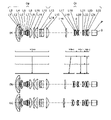
- 1, 6, 11, 16, and 21 are layout diagrams showing optical paths at the wide-angle end at an object distance of 1080 mm in the zoom lens systems according to Examples 1-5.
- 2, 7, 12, 17, and 22 are layout diagrams of the wide-angle end at the object distance of 1080 mm of the zoom lens systems according to Examples 1-5.
- FIGS. 2(a), 7(a), 12(a), 17(a), and 22(a) show lens layout diagrams at the wide-angle end of the zoom lens system.
- FIGS. 2(b), 7(b), 12(b), 17(b), and 22(b) show lens layout diagrams at intermediate positions of the zoom lens system.
- FIGS. 2(c), 7(c), 12(c), 17(c), and 22(c) show lens layout diagrams at the telephoto end of the zoom lens system.
- the wide-angle end is the shortest focal length state in which the entire system has the shortest focal length fw.
- An intermediate position is an intermediate focal length state between the wide-angle end and the telephoto end.
- the zoom lens systems according to Examples 1 to 5 internally have an intermediate imaging position MI that is conjugate with the enlargement conjugate point on the enlargement side and the reduction conjugate point on the reduction side.
- An enlarging optical system Op is arranged on the enlarging side of the intermediate imaging position MI, and a relay optical system Ol is arranged on the reducing side of the intermediate imaging position MI.
- An optical element P is arranged on the reduction side of the relay optical system Ol.
- the zoom lens systems according to Examples 1 to 5 include the first lens group G1 to the fourth lens group G4 that can move independently of each other.
- the first lens group G1 has a positive power, is composed of the first lens element L1 to the fifteenth lens element L15, and includes surfaces 1 to 30 (surface numbers refer to numerical examples described later). reference).
- the second lens group G2 has positive power, is composed of sixteenth lens element L16 to eighteenth lens element L18, and includes surfaces 31 to .
- the third lens group G3 has negative power, is composed of the 19th lens element L19 to the 22nd lens element L22, and includes surfaces 37 to 45.
- the fourth lens group G4 has positive power, is composed of the twenty-third lens element L23 to the twenty-fifth lens element L25, and includes surfaces 46 to 51.
- FIG. Optical element P includes surfaces 52-53.
- the polygonal arrows shown between each figure (a) and each figure (b) indicate, from top to bottom, the first lens group G1 to the fourth lens in each state of the wide-angle end, intermediate position, and telephoto end.
- a straight line obtained by connecting the positions of the group G4.
- the wide-angle end and the intermediate position, and the intermediate position and the telephoto end are simply connected by a straight line, which differs from the actual movements of the lens groups G1 to G4.
- the symbols (+) and (-) attached to the symbols of the lens groups G1 to G4 indicate positive and negative powers of the lens groups G1 to G4.
- the zoom lens systems according to Examples 1 to 5 have a focus lens group that performs focus adjustment when the object distance changes, and an image plane after the focus adjustment performed by the focus lens group.
- a field curvature correction lens group that corrects curvature aberration may also be included.
- the zoom lens systems according to Examples 1 to 5 include a first positive lens group GP1 having positive power, a second positive lens group GP2 having positive power, and a negative lens group GN having negative power. including.
- the first positive lens group GP1 and the negative lens group GN move independently of each other along the optical axis, while the second positive lens group GP2 remains stationary.
- the first positive lens group GP1 can function as the field curvature correction lens group described above
- the negative lens group GN can function as the focus lens group described above.
- the imaging position on the enlargement side (that is, the enlargement conjugate point) is located on the left side
- the imaging position on the reduction side (that is, the reduction conjugate point) is located on the right side.
- the straight line drawn on the side of the most reduction represents the position of the original image S
- the optical element P is positioned on the side of the enlargement of the original image S.
- the optical element P represents an optical element such as a prism for color separation and color synthesis, an optical filter, parallel plate glass, a crystal low-pass filter, and an infrared cut filter.
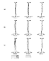
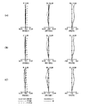
- 3, 8, 13, 18, and 23 are longitudinal aberration diagrams at an object distance of 1080 mm of the zoom lens systems according to Examples 1-5.
- 4, 9, 14, 19, and 24 are longitudinal aberration diagrams at an object distance 780 of the zoom lens systems according to Examples 1-5.
- 5, 10, 15, 20, and 25 are longitudinal aberration diagrams of the zoom lens systems according to Examples 1 to 5 at an object distance of 2900 mm.
- (a), (b), and (c) in each figure show longitudinal aberration diagrams at the wide-angle end, intermediate position, and telephoto end of the zoom lens system.
- Each longitudinal aberration diagram shows spherical aberration (SA (mm)), astigmatism (AST (mm)), and distortion (DIS (%)) in order from the left.
- the vertical axis represents the height of the pupil
- the solid line is the d-line
- the short dashed line is the F-line
- the long dashed line is the C-line.
- the vertical axis represents the image height
- the solid line is the sagittal plane (indicated by s in the figure)
- the broken line is the meridional plane (indicated by m in the figure).
- the vertical axis represents the image height.
- the distortion aberration represents the distortion aberration for equidistant projection.
- the zoom lens system according to Example 1 includes an enlarging optical system Op and a relay optical system Ol.
- the enlarging optical system Op is composed of the first lens element L1 to the twelfth lens element L12 in order from the enlarging side to the reducing side.
- the first lens element L1 has a negative meniscus shape with a convex surface facing the magnification side.
- the second lens element L2 has a positive meniscus shape with a convex surface facing the magnification side.
- the third lens element L3 has a negative meniscus shape with a convex surface facing the magnification side.
- the fourth lens element L4 has a negative meniscus shape with a convex surface facing the magnification side.
- the fifth lens element L5 has a biconvex shape.
- the sixth lens element L6 has a positive meniscus shape with a convex surface facing the reduction side.
- the seventh lens element L7 has a biconvex shape.
- the eighth lens element L8 has a biconcave shape.
- the ninth lens element L9 has a positive meniscus shape with a convex surface facing the reduction side.
- the tenth lens element L10 has a biconvex shape.
- the eleventh lens element L11 has a biconvex shape.
- the twelfth lens element L12 has a positive meniscus shape with a convex surface facing the magnification side.
- the relay optical system Ol is composed of the 13th lens element L13 to the 25th lens element L25 in order from the enlargement side to the reduction side.
- the thirteenth lens element L13 has a biconcave shape.
- the fourteenth lens element L14 has a biconcave shape.
- the fifteenth lens element L15 has a positive meniscus shape with a convex surface facing the reduction side.
- the sixteenth lens element L16 has a biconvex shape.
- the seventeenth lens element L17 has a biconcave shape.
- the eighteenth lens element L18 has a biconvex shape.
- the nineteenth lens element L19 has a positive meniscus shape with a convex surface facing the enlargement side.
- the twentieth lens element L20 has a negative meniscus shape with a convex surface facing the magnification side.
- the twenty-first lens element L21 has a negative meniscus shape with a convex surface facing the reduction side.
- the twenty-second lens element L22 has a biconvex shape.
- the twenty-third lens element L23 has a biconvex shape.
- the twenty-fourth lens element L24 has a negative meniscus shape with a convex surface facing the magnification side.
- the twenty-fifth lens element L25 has a biconvex shape.
- An intermediate imaging position MI between the twelfth lens element L12 and the thirteenth lens element L13.
- a diaphragm A is arranged between the nineteenth lens element L19 and the twentieth lens element L20.
- An optical element P whose optical power is zero is arranged on the reduction side of the relay optical system Ol.
- the first positive lens group GP1 is composed of the first lens element L1 to the ninth lens element L9.
- the second positive lens group GP2 is composed of a tenth lens element L10 to a twelfth lens element L12.
- the negative lens group GN is composed of the thirteenth lens element L13 to the fourteenth lens element L14.
- the zoom lens system according to Example 2 includes an enlarging optical system Op and a relay optical system Ol.
- the enlarging optical system Op is composed of the first lens element L1 to the twelfth lens element L12 in order from the enlarging side to the reducing side.
- the shapes of the first lens element L1 to the ninth lens element L9 and the twelfth lens element L12 are the same as those in Example 1, and redundant description will be omitted.
- the tenth lens element L10 has a positive meniscus shape with a convex surface facing the reduction side.
- the eleventh lens element L11 has a positive meniscus shape with a convex surface facing the enlargement side.
- the relay optical system Ol is composed of the 13th lens element L16 to the 25th lens element L25 in order from the enlargement side to the reduction side. These lens shapes are the same as those in Example 1, and redundant description is omitted. Arrangements of the intermediate imaging position MI, the diaphragm A and the optical element P are also the same as in the first embodiment.
- the first positive lens group GP1 is composed of the first lens element L1 to the ninth lens element L9.
- the second positive lens group GP2 is composed of a tenth lens element L10 to a twelfth lens element L12.
- the negative lens group GN is composed of the thirteenth lens element L13 to the fourteenth lens element L14.
- the zoom lens system according to Example 3 includes an enlarging optical system Op and a relay optical system Ol.
- the enlarging optical system Op is composed of the first lens element L1 to the twelfth lens element L12 in order from the enlarging side to the reducing side.
- the relay optical system Ol is composed of the 13th lens element L16 to the 25th lens element L25 in order from the enlargement side to the reduction side.
- the first positive lens group GP1 is composed of the first lens element L1 to the ninth lens element L9.
- the second positive lens group GP2 is composed of a tenth lens element L10 to a twelfth lens element L12.
- the negative lens group GN is composed of the thirteenth lens element L13 to the fourteenth lens element L14.
- the zoom lens system according to Example 4 includes an enlarging optical system Op and a relay optical system Ol.
- the enlarging optical system Op is composed of the first lens element L1 to the twelfth lens element L12 in order from the enlarging side to the reducing side.
- the relay optical system Ol is composed of the 13th lens element L16 to the 25th lens element L25 in order from the enlargement side to the reduction side.
- the first positive lens group GP1 is composed of the second lens element L2 to the ninth lens element L9.
- the second positive lens group GP2 is composed of a tenth lens element L10 to a twelfth lens element L12.
- the negative lens group GN is composed of the thirteenth lens element L13 to the fourteenth lens element L14.
- the first lens element L1 is stationary during focusing.
- the zoom lens system according to Example 5 includes an enlarging optical system Op and a relay optical system Ol.
- the enlarging optical system Op is composed of the first lens element L1 to the twelfth lens element L12 in order from the enlarging side to the reducing side.
- These lens shapes are the same as those in Example 1, and redundant description is omitted.
- the relay optical system Ol is composed of the 13th lens element L16 to the 25th lens element L25 in order from the enlargement side to the reduction side.
- the thirteenth lens element L13 has a negative meniscus shape with a convex surface facing the magnification side.
- the shapes of the fourteenth lens element L14 to the twenty-fifth lens element L25 are the same as those of the first embodiment, and redundant description is omitted. Arrangements of the intermediate imaging position MI, the diaphragm A and the optical element P are also the same as in the first embodiment.
- the first positive lens group GP1 is composed of the first lens element L1 to the ninth lens element L9.
- the second positive lens group GP2 is composed of a tenth lens element L10 to a twelfth lens element L12.
- the negative lens group GN is composed of a fourteenth lens element L14.
- the thirteenth lens element L13 is stationary during focusing.
- the zoom lens systems according to Examples 1 to 5 are optical systems that internally have an intermediate imaging position MI that is conjugate with an enlargement-side enlargement conjugate point and a reduction-side reduction conjugate point, respectively, a first positive lens group GP1 having a plurality of lens elements and positioned on the enlargement side of the intermediate imaging position; a second positive lens group GP2 having a plurality of lens elements and positioned between the first positive lens group GP1 and the intermediate imaging position M1; a negative lens group GN having a plurality of lens elements and positioned on the reduction side of the intermediate imaging position MI; During focusing, the first positive lens group GP1 and the negative lens group GN move along the optical axis, while the second positive lens group GP2 remains stationary.
- the first positive lens group has a small change in back focus and a large change in curvature of field with respect to movement. Since the negative lens group has a small change in curvature of field and a large change in back focus with respect to movement, focus adjustment is facilitated. In addition, since the negative lens group can have a small lens diameter, it is possible to reduce the size and weight of the focusing structure.
- zoom lens systems according to Examples 1 to 5 may satisfy the following condition (1). 0.10 ⁇ p2 ⁇ 0.35 (1) here, ⁇ p2: lateral magnification of the second positive lens group GP2.
- condition (1) it is possible to reduce the fluctuation of the back focus when the first positive lens group moves, and it is easy to correct the curvature of field generated in the first positive lens group, and to easily adjust the focus. Become. When the upper limit is exceeded, the back focus fluctuation of the first positive lens group becomes large. Conversely, if the lower limit is not reached, astigmatism will increase during focus adjustment.
- zoom lens systems according to Examples 1 to 5 may satisfy the following condition (2). 0.2 ⁇ n ⁇ 1.0 (2) here, ⁇ n: lateral magnification of the negative lens group GN.
- the back focus variation increases when the negative lens group moves, and focus adjustment becomes easier. If the upper limit is exceeded, the occurrence of aberration due to eccentricity during manufacturing increases. Conversely, when the lower limit is not reached, the back focus sensitivity during focus adjustment is reduced, and field curvature is relatively likely to occur.
- zoom lens systems according to Examples 1 to 5 may satisfy the following condition (3). ⁇ 0.2 ⁇ p1 ⁇ 0.0 (3) here, ⁇ p1: lateral magnification of the first positive lens group GP1.
- the condition (3) it is possible to reduce the fluctuation of the back focus when the first positive lens group moves, and it is easy to correct the curvature of field generated in the first positive lens group, and to easily adjust the focus. Become. When the upper limit is exceeded, the back focus fluctuation of the first positive lens group becomes large. Conversely, if the lower limit is not reached, the back focus fluctuation of the first positive lens group will increase.
- zoom lens systems according to Examples 1 to 5 may satisfy the following condition (4). 2.0 ⁇ fp1/fo ⁇ 10.0 (4) here, fp1: the focal length of the first positive lens group GP1 fo: the focal length of the entire enlarging optical system Op located on the enlarging side of the intermediate imaging position MI.
- Condition (4) is a conditional expression for defining the relationship between the focal length of the first positive lens group and the focal length of the entire enlarging optical system located on the enlarging side of the intermediate imaging position.
- zoom lens systems according to Examples 1 to 5 may satisfy the following condition (5). ⁇ 5.0 ⁇ fn/fo ⁇ 1.0 (5) here, fn: the focal length of the negative lens group GN fo: the focal length of the entire enlarging optical system Op located on the enlarging side of the intermediate imaging position MI.
- Condition (5) is a conditional expression for defining the relationship between the focal length of the negative lens group and the focal length of the entire enlarging optical system located on the enlarging side of the intermediate imaging position.
- the lens element on the most magnification side located on the most magnification side of the second positive lens group GP2 has positive power and satisfies the following condition (6).
- condition (6) may -1.40 ⁇ (R2+R1)/(R2-R1) ⁇ -0.70 (6)
- R2 radius of curvature of the reduction side surface of the lens element on the maximum magnification side.
- Condition (6) is a conditional expression for defining the relationship between the radius of curvature of the enlargement side surface and the radius of curvature of the reduction side surface of the maximum magnification side lens element.
- the zoom lens systems according to Examples 1 to 5 may further include an adjacent lens element having positive power adjacent to the reduction side of the negative lens group GN, and satisfy the following condition (7).
- the adjacent lens element may be a fifteenth lens element L15 having a positive meniscus shape with a convex surface facing the reduction side.
- the zoom lens systems according to Examples 1 to 5 may further include an adjacent lens element having positive power adjacent to the reduction side of the negative lens group GN, and satisfy the following condition (8). 25 ⁇ vpd ⁇ 30 (8) here, vpd: Abbe number of the adjacent lens element.
- the negative lens group GN may include a lens element positioned most on the enlargement side among a plurality of lens elements positioned on the reduction side of the intermediate imaging position MI. .
- the negative lens group GN may include the thirteenth lens element L13 positioned most on the enlargement side among the plurality of lens elements L13 to L25 positioned on the reduction side of the intermediate imaging position MI. good.
- the negative lens group GN may be composed of two lens elements having a biconcave shape.
- the negative lens group GN may be composed of a biconcave 13th lens element L13 and a biconcave 14th lens element L14.
- the first positive lens group GP1 is the lens element positioned most on the enlargement side among the plurality of lens elements positioned on the enlargement side of the intermediate imaging position MI.
- the configuration of the focus mechanism member can be simplified.
- the first positive lens group GP1 is the first lens element positioned most on the enlargement side among the plurality of lens elements L1 to L12 positioned on the enlargement side of the intermediate imaging position MI. L1 may be included.
- Z the distance from a point on the aspherical surface whose height from the optical axis is h to the plane tangent to the apex of the aspherical surface; h: height from the optical axis, r: vertex curvature radius, ⁇ : conic constant, An: An n-th order aspheric coefficient.
- Table 7 shows surface data
- Table 8 shows various data
- Table 9 shows focus data
- Table 10 shows single lens data
- Zoom lens group data is shown in Table 11
- zoom lens group magnification is shown in Table 12 (unit: mm).
- Table 13 shows surface data
- Table 14 shows various data
- Table 15 shows focus data
- Table 16 shows single lens data
- Zoom lens group data is shown in Table 17
- zoom lens group magnification is shown in Table 18 (unit: mm).
- Table 31 shows the corresponding values of each conditional expression (1) to (8) in each numerical example.
- Table 32 shows the values of the variables of each conditional expression (1) to (8) in each numerical example.
- [Table 32] fo: focal length of the entire enlarging optical system located on the enlarging side of the intermediate image forming position fp1: focal length of the first positive lens group fn: focal length of the negative lens group R1: focal length of the enlarging-side surface of the lens element on the highest magnification side Curvature radius R2: Curvature radius of the reduction side surface of the lens element on the maximum magnification side
- FIG. 26 is a block diagram showing an example of an image projection device according to the present disclosure.
- the image projection apparatus 100 includes the optical system 1 disclosed in the first embodiment, an image forming element 101, a light source 102, a control section 110, and the like.
- the image forming element 101 is composed of liquid crystal, DMD, etc., and generates an image to be projected onto the screen SR via the optical system 1 .
- a light source 102 is composed of an LED (light emitting diode), a laser, or the like, and supplies light to the image forming element 101 .
- the control unit 110 is composed of a CPU, an MPU, or the like, and controls the entire apparatus and each component.
- the optical system 1 may be configured as an interchangeable lens that can be detachably attached to the image projection apparatus 100 . In this case, an apparatus obtained by removing the optical system 1 from the image projection apparatus 100 is an example of the main apparatus.
- the image projection apparatus 100 described above can realize a wide-angle zoom function by the optical system 1 according to the first embodiment, and the size and weight of the apparatus can be reduced.
- FIG. 27 is a block diagram illustrating an example of an imaging device according to the present disclosure.
- the imaging device 200 includes the optical system 1 disclosed in the first embodiment, an imaging device 201, a control unit 210, and the like.
- the imaging device 201 is composed of a CCD (charge-coupled device) image sensor, a CMOS image sensor, or the like, receives an optical image of an object OBJ formed by the optical system 1, and converts it into an electrical image signal.
- the control unit 110 is composed of a CPU, an MPU, or the like, and controls the entire apparatus and each component.
- the optical system 1 may be configured as an interchangeable lens that can be detachably attached to the imaging device 200 . In this case, a device obtained by removing the optical system 1 from the imaging device 200 is an example of the main device.
- the imaging device 200 described above can realize a wide-angle zoom function by the optical system 1 according to the first embodiment, and the size and weight of the device can be reduced.
- the present disclosure is applicable to image projection devices such as projectors and head-up displays, and imaging devices such as digital still cameras, digital video cameras, surveillance cameras in surveillance systems, web cameras, and vehicle-mounted cameras.
- imaging devices such as digital still cameras, digital video cameras, surveillance cameras in surveillance systems, web cameras, and vehicle-mounted cameras.
- the present disclosure is applicable to optical systems that require high image quality, such as projectors, digital still camera systems, and digital video camera systems.
Abstract
Description
複数のレンズ素子を有し、前記中間結像位置より拡大側に位置する第1正レンズ群と、
複数のレンズ素子を有し、前記第1正レンズ群と前記中間結像位置との間に位置する第2正レンズ群と、
複数のレンズ素子を有し、前記中間結像位置より縮小側に位置する負レンズ群とを備え、
フォーカシングの際に、前記第1正レンズ群および前記負レンズ群は光軸方向に移動し、前記第2正レンズ群は静止している。 An optical system according to the present disclosure is an optical system that internally includes an intermediate imaging position that is conjugate with an expansion conjugate point on the expansion side and a reduction conjugate point on the reduction side,
a first positive lens group having a plurality of lens elements and positioned on the enlargement side of the intermediate imaging position;
a second positive lens group having a plurality of lens elements and positioned between the first positive lens group and the intermediate imaging position;
a negative lens group having a plurality of lens elements and positioned on the reduction side of the intermediate imaging position;
During focusing, the first positive lens group and the negative lens group move along the optical axis, and the second positive lens group remains stationary.
以下、図1~図25を用いて本開示の実施形態1を説明する。ここでは、光学系の一例としてズームレンズ系について説明する。 (Embodiment 1)
図1、2に示すように、実施例1に係るズームレンズ系は、拡大光学系Opとリレー光学系Olとを備える。拡大光学系Opは、拡大側から縮小側へと順に、第1レンズ素子L1から第12レンズ素子L12で構成される。第1レンズ素子L1は、拡大側に凸面を向けた負メニスカス形状を有する。第2レンズ素子L2は、拡大側に凸面を向けた正メニスカス形状を有する。第3レンズ素子L3は、拡大側に凸面を向けた負メニスカス形状を有する。第4レンズ素子L4は、拡大側に凸面を向けた負メニスカス形状を有する。第5レンズ素子L5は、両凸形状を有する。第6レンズ素子L6は、縮小側に凸面を向けた正メニスカス形状を有する。第7レンズ素子L7は、両凸形状を有する。第8レンズ素子L8は、両凹形状を有する。第9レンズ素子L9は、縮小側に凸面を向けた正メニスカス形状を有する。第10レンズ素子L10は、両凸形状を有する。第11レンズ素子L11は、両凸形状を有する。第12レンズ素子L12は、拡大側に凸面を向けた正メニスカス形状を有する。 (Example 1)
As shown in FIGS. 1 and 2, the zoom lens system according to Example 1 includes an enlarging optical system Op and a relay optical system Ol. The enlarging optical system Op is composed of the first lens element L1 to the twelfth lens element L12 in order from the enlarging side to the reducing side. The first lens element L1 has a negative meniscus shape with a convex surface facing the magnification side. The second lens element L2 has a positive meniscus shape with a convex surface facing the magnification side. The third lens element L3 has a negative meniscus shape with a convex surface facing the magnification side. The fourth lens element L4 has a negative meniscus shape with a convex surface facing the magnification side. The fifth lens element L5 has a biconvex shape. The sixth lens element L6 has a positive meniscus shape with a convex surface facing the reduction side. The seventh lens element L7 has a biconvex shape. The eighth lens element L8 has a biconcave shape. The ninth lens element L9 has a positive meniscus shape with a convex surface facing the reduction side. The tenth lens element L10 has a biconvex shape. The eleventh lens element L11 has a biconvex shape. The twelfth lens element L12 has a positive meniscus shape with a convex surface facing the magnification side.
図6、7に示すように、実施例2に係るズームレンズ系は、拡大光学系Opとリレー光学系Olとを備える。拡大光学系Opは、拡大側から縮小側へと順に、第1レンズ素子L1から第12レンズ素子L12で構成される。第1レンズ素子L1~第9レンズ素子L9および第12レンズ素子L12の形状は、実施例1と同様であり、重複説明を省く。第10レンズ素子L10は、縮小側に凸面を向けた正メニスカス形状を有する。第11レンズ素子L11は、拡大側に凸面を向けた正メニスカス形状を有する。 (Example 2)
As shown in FIGS. 6 and 7, the zoom lens system according to Example 2 includes an enlarging optical system Op and a relay optical system Ol. The enlarging optical system Op is composed of the first lens element L1 to the twelfth lens element L12 in order from the enlarging side to the reducing side. The shapes of the first lens element L1 to the ninth lens element L9 and the twelfth lens element L12 are the same as those in Example 1, and redundant description will be omitted. The tenth lens element L10 has a positive meniscus shape with a convex surface facing the reduction side. The eleventh lens element L11 has a positive meniscus shape with a convex surface facing the enlargement side.
図11、12に示すように、実施例3に係るズームレンズ系は、拡大光学系Opとリレー光学系Olとを備える。拡大光学系Opは、拡大側から縮小側へと順に、第1レンズ素子L1から第12レンズ素子L12で構成される。リレー光学系Olは、拡大側から縮小側へと順に、第13レンズ素子L16から第25レンズ素子L25で構成される。これらのレンズ形状は、実施例1と同様であり、重複説明を省く。中間結像位置MI、絞りAおよび光学素子Pの配置についても実施例1と同様である。 (Example 3)
As shown in FIGS. 11 and 12, the zoom lens system according to Example 3 includes an enlarging optical system Op and a relay optical system Ol. The enlarging optical system Op is composed of the first lens element L1 to the twelfth lens element L12 in order from the enlarging side to the reducing side. The relay optical system Ol is composed of the 13th lens element L16 to the 25th lens element L25 in order from the enlargement side to the reduction side. These lens shapes are the same as those in Example 1, and redundant description is omitted. Arrangements of the intermediate imaging position MI, the diaphragm A and the optical element P are also the same as in the first embodiment.
図16、17に示すように、実施例4に係るズームレンズ系は、拡大光学系Opとリレー光学系Olとを備える。拡大光学系Opは、拡大側から縮小側へと順に、第1レンズ素子L1から第12レンズ素子L12で構成される。リレー光学系Olは、拡大側から縮小側へと順に、第13レンズ素子L16から第25レンズ素子L25で構成される。これらのレンズ形状は、実施例1と同様であり、重複説明を省く。中間結像位置MI、絞りAおよび光学素子Pの配置についても実施例1と同様である。 (Example 4)
As shown in FIGS. 16 and 17, the zoom lens system according to Example 4 includes an enlarging optical system Op and a relay optical system Ol. The enlarging optical system Op is composed of the first lens element L1 to the twelfth lens element L12 in order from the enlarging side to the reducing side. The relay optical system Ol is composed of the 13th lens element L16 to the 25th lens element L25 in order from the enlargement side to the reduction side. These lens shapes are the same as those in Example 1, and redundant description is omitted. Arrangements of the intermediate imaging position MI, the diaphragm A and the optical element P are also the same as in the first embodiment.
図21、22に示すように、実施例5に係るズームレンズ系は、拡大光学系Opとリレー光学系Olとを備える。拡大光学系Opは、拡大側から縮小側へと順に、第1レンズ素子L1から第12レンズ素子L12で構成される。これらのレンズ形状は、実施例1と同様であり、重複説明を省く。 (Example 5)
As shown in FIGS. 21 and 22, the zoom lens system according to Example 5 includes an enlarging optical system Op and a relay optical system Ol. The enlarging optical system Op is composed of the first lens element L1 to the twelfth lens element L12 in order from the enlarging side to the reducing side. These lens shapes are the same as those in Example 1, and redundant description is omitted.
複数のレンズ素子を有し、前記中間結像位置より拡大側に位置する第1正レンズ群GP1と、
複数のレンズ素子を有し、前記第1正レンズ群GP1と前記中間結像位置M1との間に位置する第2正レンズ群GP2と、
複数のレンズ素子を有し、前記中間結像位置MIより縮小側に位置する負レンズ群GNとを備え、
フォーカシングの際に、前記第1正レンズ群GP1および前記負レンズ群GNは光軸方向に移動し、前記第2正レンズ群GP2は静止している。 The zoom lens systems according to Examples 1 to 5 are optical systems that internally have an intermediate imaging position MI that is conjugate with an enlargement-side enlargement conjugate point and a reduction-side reduction conjugate point, respectively,
a first positive lens group GP1 having a plurality of lens elements and positioned on the enlargement side of the intermediate imaging position;
a second positive lens group GP2 having a plurality of lens elements and positioned between the first positive lens group GP1 and the intermediate imaging position M1;
a negative lens group GN having a plurality of lens elements and positioned on the reduction side of the intermediate imaging position MI;
During focusing, the first positive lens group GP1 and the negative lens group GN move along the optical axis, while the second positive lens group GP2 remains stationary.
0.10<βp2<0.35 …(1)
ここで、
βp2:前記第2正レンズ群GP2の横倍率
である。 Further, the zoom lens systems according to Examples 1 to 5 may satisfy the following condition (1).
0.10<βp2<0.35 (1)
here,
βp2: lateral magnification of the second positive lens group GP2.
0.21<βp2<0.25 …(1A) By satisfying the following condition (1A) in addition to the condition (1), a more advantageous effect can be obtained.
0.21<βp2<0.25 (1A)
0.2<βn<1.0 …(2)
ここで、
βn:前記負レンズ群GNの横倍率
である。 Further, the zoom lens systems according to Examples 1 to 5 may satisfy the following condition (2).
0.2<βn<1.0 (2)
here,
βn: lateral magnification of the negative lens group GN.
0.4<βn<0.7 …(2A) By satisfying the following condition (2A) in addition to the condition (2), a more advantageous effect can be obtained.
0.4<βn<0.7 (2A)
-0.2<βp1<0.0 …(3)
ここで、
βp1:前記第1正レンズ群GP1の横倍率
である。 Further, the zoom lens systems according to Examples 1 to 5 may satisfy the following condition (3).
−0.2<βp1<0.0 (3)
here,
βp1: lateral magnification of the first positive lens group GP1.
2.0<fp1/fo<10.0 …(4)
ここで、
fp1:前記第1正レンズ群GP1の焦点距離
fo:前記中間結像位置MIより拡大側に位置する拡大光学系Op全体の焦点距離
である。 Further, the zoom lens systems according to Examples 1 to 5 may satisfy the following condition (4).
2.0<fp1/fo<10.0 (4)
here,
fp1: the focal length of the first positive lens group GP1 fo: the focal length of the entire enlarging optical system Op located on the enlarging side of the intermediate imaging position MI.
3.5<fp1/fo<5.0 …(4A) By satisfying the following condition (4A) in addition to the condition (4), a more advantageous effect can be obtained.
3.5<fp1/fo<5.0 (4A)
-5.0<fn/fo<-1.0 …(5)
ここで、
fn:前記負レンズ群GNの焦点距離
fo:前記中間結像位置MIより拡大側に位置する拡大光学系Op全体の焦点距離
である。 Further, the zoom lens systems according to Examples 1 to 5 may satisfy the following condition (5).
−5.0<fn/fo<−1.0 (5)
here,
fn: the focal length of the negative lens group GN fo: the focal length of the entire enlarging optical system Op located on the enlarging side of the intermediate imaging position MI.
-2.0<fn/fo<-1.4 …(5A) By satisfying the following condition (5A) in addition to the condition (5), a more advantageous effect can be obtained.
−2.0<fn/fo<−1.4 (5A)
-1.40<(R2+R1)/(R2-R1)<-0.70 …(6)
R1:前記最拡大側レンズ素子の拡大側の面の曲率半径
R2:前記最拡大側レンズ素子の縮小側の面の曲率半径
である。 Further, in the zoom lens systems according to Examples 1 to 5, the lens element on the most magnification side located on the most magnification side of the second positive lens group GP2 has positive power and satisfies the following condition (6). may
-1.40<(R2+R1)/(R2-R1)<-0.70 (6)
R1: radius of curvature of the enlargement side surface of the lens element on the maximum magnification side R2: radius of curvature of the reduction side surface of the lens element on the maximum magnification side.
一例として、実施例1~5において、第2正レンズ群GP2の最も拡大側に位置する最拡大側レンズ素子は、両凸形状または縮小側に凸面を向けた正メニスカス形状を有する第10レンズ素子L10でもよい。 Condition (6) is a conditional expression for defining the relationship between the radius of curvature of the enlargement side surface and the radius of curvature of the reduction side surface of the maximum magnification side lens element. By satisfying the condition (6), it is possible to reduce back focus variation when the first positive lens group moves. If the upper limit is exceeded, the back focus fluctuation when the first positive lens group is moved becomes large.
As an example, in Examples 1 to 5, the lens element on the most magnification side located on the most magnification side of the second positive lens group GP2 is a tenth lens element having a biconvex shape or a positive meniscus shape with a convex surface facing the reduction side. It may be L10.
-1.10<(R2+R1)/(R2-R1)<-0.84 …(6A) By satisfying the following condition (6A) in addition to the condition (6), a more advantageous effect can be obtained.
-1.10<(R2+R1)/(R2-R1)<-0.84 (6A)
npd>1.85 …(7)
ここで、
npd:前記隣接レンズ素子の屈折率
である。 Further, the zoom lens systems according to Examples 1 to 5 may further include an adjacent lens element having positive power adjacent to the reduction side of the negative lens group GN, and satisfy the following condition (7).
npd>1.85 (7)
here,
npd: refractive index of the adjacent lens element.
一例として、実施例1~5において、前記隣接レンズ素子は、縮小側に凸面を向けた正メニスカス形状を有する第15レンズ素子L15でもよい。 By satisfying the condition (7), it is possible to reduce fluctuations in curvature of field when the negative lens group moves.
As an example, in Examples 1 to 5, the adjacent lens element may be a fifteenth lens element L15 having a positive meniscus shape with a convex surface facing the reduction side.
25<vpd<30 …(8)
ここで、
vpd:前記隣接レンズ素子のアッベ数
である。 Further, the zoom lens systems according to Examples 1 to 5 may further include an adjacent lens element having positive power adjacent to the reduction side of the negative lens group GN, and satisfy the following condition (8).
25<vpd<30 (8)
here,
vpd: Abbe number of the adjacent lens element.
一例として、実施例1~4において、負レンズ群GNは、中間結像位置MIより縮小側に位置する複数のレンズ素子L13~L25のうち最も拡大側に位置する第13レンズ素子L13を含んでもよい。 With such a configuration, fluctuations in field curvature can be reduced when the negative lens group moves.
As an example, in Examples 1 to 4, the negative lens group GN may include the thirteenth lens element L13 positioned most on the enlargement side among the plurality of lens elements L13 to L25 positioned on the reduction side of the intermediate imaging position MI. good.
一例として、実施例1~4において、負レンズ群GNは、両凹形状を有する第13レンズ素子L13と、両凹形状を有する第14レンズ素子L14とで構成してもよい。 According to such a configuration, it is possible to increase the back focus fluctuation when the negative lens group moves and to reduce the occurrence of curvature of field. As a result, the role of focus adjustment can be shared, so focus adjustment can be easily performed.
As an example, in Examples 1 to 4, the negative lens group GN may be composed of a biconcave 13th lens element L13 and a biconcave 14th lens element L14.
一例として、実施例1~3,5において、第1正レンズ群GP1は、中間結像位置MIより拡大側に位置する複数のレンズ素子L1~L12のうち最も拡大側に位置する第1レンズ素子L1を含んでもよい。 With such a configuration, the configuration of the focus mechanism member can be simplified.
As an example, in Examples 1 to 3 and 5, the first positive lens group GP1 is the first lens element positioned most on the enlargement side among the plurality of lens elements L1 to L12 positioned on the enlargement side of the intermediate imaging position MI. L1 may be included.

Z:光軸からの高さがhの非球面上の点から、非球面頂点の接平面までの距離、
h:光軸からの高さ、
r:頂点曲率半径、
κ:円錐定数、
An:n次の非球面係数
である。 here,
Z: the distance from a point on the aspherical surface whose height from the optical axis is h to the plane tangent to the apex of the aspherical surface;
h: height from the optical axis,
r: vertex curvature radius,
κ: conic constant,
An: An n-th order aspheric coefficient.
数値実施例1(実施例1に対応)のズームレンズ系について、面データを表1に示し、各種データを表2に示し、フォーカスデータを表3に示し、単レンズデータを表4に示し、ズームレンズ群データを表5に示し、ズームレンズ群倍率を表6に示す(単位はmm)。 (Numerical example 1)
Regarding the zoom lens system of Numerical Example 1 (corresponding to Example 1), surface data are shown in Table 1, various data are shown in Table 2, focus data are shown in Table 3, single lens data are shown in Table 4, Zoom lens group data is shown in Table 5, and zoom lens group magnification is shown in Table 6 (unit: mm).
面データ
面番号 r d nd vd
物面 ∞
1 82.55780 4.50000 1.84666 23.8
2 44.55160 11.06650
3 69.33030 8.52300 1.85883 30.0
4 133.67220 0.20010
5 50.85360 2.50000 1.87071 40.7
6 24.24730 6.50560
7* 24.00860 2.60000 1.58560 58.9
8* 12.32090 12.86710
9 80.89650 3.52100 1.51680 64.2
10 -222.82880 6.22010
11 -290.61360 2.96520 1.61997 63.9
12 -44.67100 0.87470
13 137.60190 7.95190 1.43700 95.1
14 -22.20850 1.94110
15 -26.19400 1.50000 1.86966 20.0
16 413.84650 3.99060
17* -44.70600 7.03060 1.80755 40.9
18* -21.48260 2.27070
19 601.51980 13.55710 1.49700 81.6
20 -42.87920 8.69250
21 100.40190 8.17950 1.92286 20.9
22 -2603.87270 0.20000
23 38.37610 14.18340 1.92286 20.9
24 84.65110 14.82680
25 -242.34250 5.00000 1.80809 22.8
26 38.72750 9.94890
27 -42.25540 10.00000 1.77047 29.7
28 144.66080 20.27510
29 -132.28900 12.06400 1.85451 25.2
30 -44.68970 可変
31 189.92110 6.10080 1.77250 49.6
32 -189.92110 45.81600
33 -58.71800 1.50000 1.59270 35.4
34 58.71800 2.86370
35 67.66000 8.00090 1.49700 81.6
36 -48.05880 可変
37 30.13800 6.14480 1.67300 38.3
38 75.30020 1.92430
39(絞り) ∞ 0.20000
40 39.00960 1.50000 1.51680 64.2
41 19.53140 28.21900
42 -25.33820 1.50000 1.73800 32.3
43 -275.52850 1.10580
44 277.84170 8.01780 1.43700 95.1
45 -29.61870 可変
46 68.93650 7.82660 1.49700 81.6
47 -68.93650 1.30510
48 63.66180 1.80000 1.73800 32.3
49 31.89260 3.18230
50 37.30830 10.18660 1.43700 95.1
51 -78.81430 可変
52(P) ∞ 31.90000 1.51680 64.2
53 ∞ BF
像面 ∞
非球面データ
第7面
K= 0.00000E+00, A4=7.56283E-07, A6=-7.89853E-08, A8= 1.03168E-10,
A10=-2.03953E-13, A12=1.61052E-16
第8面
K=-8.25316E-01, A4=-7.92622E-06, A6=-1.12300E-07, A8=-1.78382E-10,
A10=5.29776E-13, A12=7.12021E-16
第17面
K= 0.00000E+00, A4=4.30120E-07, A6=1.36064E-08, A8=-2.16679E-10,
A10=8.30030E-13, A12=-8.45350E-16
第18面
K= 0.00000E+00, A4=1.04919E-05, A6=1.31013E-08, A8=7.83133E-11,
A10=-3.79608E-13, A12= 1.00893E-15 [Table 1]
Surface data Surface number r d nd vd
object ∞
1 82.55780 4.50000 1.84666 23.8
2 44.55160 11.06650
3 69.33030 8.52300 1.85883 30.0
4 133.67220 0.20010
5 50.85360 2.50000 1.87071 40.7
6 24.24730 6.50560
7* 24.00860 2.60000 1.58560 58.9
8* 12.32090 12.86710
9 80.89650 3.52100 1.51680 64.2
10 -222.82880 6.22010
11 -290.61360 2.96520 1.61997 63.9
12 -44.67100 0.87470
13 137.60190 7.95190 1.43700 95.1
14 -22.20850 1.94110
15 -26.19400 1.50000 1.86966 20.0
16 413.84650 3.99060
17* -44.70600 7.03060 1.80755 40.9
18* -21.48260 2.27070
19 601.51980 13.55710 1.49700 81.6
20 -42.87920 8.69250
21 100.40190 8.17950 1.92286 20.9
22 -2603.87270 0.20000
23 38.37610 14.18340 1.92286 20.9
24 84.65110 14.82680
25 -242.34250 5.00000 1.80809 22.8
26 38.72750 9.94890
27 -42.25540 10.00000 1.77047 29.7
28 144.66080 20.27510
29 -132.28900 12.06400 1.85451 25.2
30 -44.68970 variable
31 189.92110 6.10080 1.77250 49.6
32 -189.92110 45.81600
33 -58.71800 1.50000 1.59270 35.4
34 58.71800 2.86370
35 67.66000 8.00090 1.49700 81.6
36 -48.05880 variable
37 30.13800 6.14480 1.67300 38.3
38 75.30020 1.92430
39 (Aperture) ∞ 0.20000
40 39.00960 1.50000 1.51680 64.2
41 19.53140 28.21900
42 -25.33820 1.50000 1.73800 32.3
43 -275.52850 1.10580
44 277.84170 8.01780 1.43700 95.1
45 -29.61870 variable
46 68.93650 7.82660 1.49700 81.6
47 -68.93650 1.30510
48 63.66180 1.80000 1.73800 32.3
49 31.89260 3.18230
50 37.30830 10.18660 1.43700 95.1
51 -78.81430 variable
52(P) ∞ 31.90000 1.51680 64.2
53∞BF
Image plane ∞
Aspheric surface data 7th surface
K= 0.00000E+00, A4=7.56283E-07, A6=-7.89853E-08, A8= 1.03168E-10,
A10=-2.03953E-13, A12=1.61052E-16
8th side
K=-8.25316E-01, A4=-7.92622E-06, A6=-1.12300E-07, A8=-1.78382E-10,
A10=5.29776E-13, A12=7.12021E-16
17th side
K= 0.00000E+00, A4=4.30120E-07, A6=1.36064E-08, A8=-2.16679E-10,
A10=8.30030E-13, A12=-8.45350E-16
18th side
K= 0.00000E+00, A4=1.04919E-05, A6=1.31013E-08, A8=7.83133E-11,
A10=-3.79608E-13, A12= 1.00893E-15
各種データ
ズーム比 1.07260
広角 中間 望遠
焦点距離 -5.4391 -5.6167 -5.8340
Fナンバー -1.99438 -1.99438 -1.99519
画角 -67.2435 -66.6302 -65.8817
像高 13.2500 13.2500 13.2500
レンズ全長 495.0099 495.0181 495.0277
BF 1.71841 1.72656 1.73617
d30 98.8440 93.2447 86.3781
d36 2.0005 7.5998 14.4664
d45 3.0311 2.6032 2.0000
d51 16.3667 16.7946 17.3978
入射瞳位置 33.6261 33.6530 33.6907
射出瞳位置 -1230.1264-1034.2082 -844.6386
前側主点位置 28.1630 28.0059 27.8166
後側主点位置 500.4225 500.6064 500.8311 [Table 2]
Various data Zoom ratio 1.07260
Wide Medium Telephoto Focal length -5.4391 -5.6167 -5.8340
F number -1.99438 -1.99438 -1.99519
Angle of view -67.2435 -66.6302 -65.8817
Image height 13.2500 13.2500 13.2500
Total lens length 495.0099 495.0181 495.0277
BF 1.71841 1.72656 1.73617
d30 98.8440 93.2447 86.3781
d36 2.0005 7.5998 14.4664
d45 3.0311 2.6032 2.0000
d51 16.3667 16.7946 17.3978
Entrance pupil position 33.6261 33.6530 33.6907
Exit pupil position -1230.1264-1034.2082 -844.6386
Front principal point position 28.1630 28.0059 27.8166
Rear principal point position 500.4225 500.6064 500.8311
フォーカスデータ
広角 中間 望遠
物体距離 1080
d18 2.271 2.271 2.271
d24 14.827 14.827 14.827
d28 20.275 20.275 20.275
物体距離 780
d18 2.458 2.447 2.437
d24 14.793 14.798 14.810
d28 20.309 20.303 20.292
物体距離 2900
d18 2.024 2.018 2.013
d24 14.834 14.837 14.841
d28 20.268 20.264 20.261 [Table 3]
Focus Data Wide Angle Medium Telephoto Object Distance 1080
d18 2.271 2.271 2.271
d24 14.827 14.827 14.827
d28 20.275 20.275 20.275
object distance 780
d18 2.458 2.447 2.437
d24 14.793 14.798 14.810
d28 20.309 20.303 20.292
object distance 2900
d18 2.024 2.018 2.013
d24 14.834 14.837 14.841
d28 20.268 20.264 20.261
単レンズデータ
レンズ 始面 焦点距離
1 1 -120.8636
2 3 158.0385
3 5 -55.6610
4 7 -47.0881
5 9 115.2969
6 11 84.7502
7 13 44.4302
8 15 -28.2820
9 17 45.1092
10 19 81.1016
11 21 104.9074
12 23 66.3145
13 25 -40.9955
14 27 -41.4796
15 29 74.2670
16 31 123.7928
17 33 -49.2997
18 35 57.8669
19 37 70.7909
20 40 -77.7289
21 42 -37.9073
22 44 61.7376
23 46 70.6848
24 48 -88.7325
25 50 59.5325 [Table 4]
Single Lens Data Lens Starting
2 3 158.0385
3 5 -55.6610
4 7 -47.0881
5 9 115.2969
6 11 84.7502
7 13 44.4302
8 15 -28.2820
9 17 45.1092
10 19 81.1016
11 21 104.9074
12 23 66.3145
13 25 -40.9955
14 27 -41.4796
15 29 74.2670
16 31 123.7928
17 33 -49.2997
18 35 57.8669
19 37 70.7909
20 40 -77.7289
21 42 -37.9073
22 44 61.7376
23 46 70.6848
24 48 -88.7325
25 50 59.5325
ズームレンズ群データ
群 始面 焦点距離 レンズ構成長 前側主点位置 後側主点位置
1 1 16.25114 203.95550 50.63261 62.90935
2 31 148.60132 64.28140 13.41062 8.57894
3 37 -354.97558 48.61170 99.51621 83.49706
4 46 52.88173 24.30060 8.67722 13.88961 [Table 5]
Zoom lens group data Group Starting surface Focal length Lens length Position of front principal point Position of rear
2 31 148.60132 64.28140 13.41062 8.57894
3 37 -354.97558 48.61170 99.51621 83.49706
4 46 52.88173 24.30060 8.67722 13.88961
ズームレンズ群倍率
群 始面 広角 中間 望遠
1 1 -0.01458 -0.01458 -0.01458
2 31 -1.68461 -1.79879 -1.96185
3 37 3.13420 3.48388 4.19963
4 46 0.06343 0.05519 0.04360 [Table 6]
Zoom Lens Group Magnification Group First Wide
2 31 -1.68461 -1.79879 -1.96185
3 37 3.13420 3.48388 4.19963
4 46 0.06343 0.05519 0.04360
数値実施例2(実施例2に対応)のズームレンズ系について、面データを表7に示し、各種データを表8に示し、フォーカスデータを表9に示し、単レンズデータを表10に示し、ズームレンズ群データを表11に示し、ズームレンズ群倍率を表12に示す(単位はmm)。 (Numerical example 2)
Table 7 shows surface data, Table 8 shows various data, Table 9 shows focus data, Table 10 shows single lens data, and Zoom lens group data is shown in Table 11, and zoom lens group magnification is shown in Table 12 (unit: mm).
面データ
面番号 r d nd vd
物面 ∞
1 78.65380 4.50000 1.84666 23.8
2 44.66850 10.81770
3 67.01600 8.57080 1.85883 30.0
4 120.35830 0.20000
5 52.79860 2.50000 1.87071 40.7
6 24.31400 7.37020
7* 24.00100 2.60000 1.58560 58.9
8* 12.32940 12.02600
9 76.12200 3.91680 1.51680 64.2
10 -227.26320 6.11480
11 -134.82570 2.72200 1.61997 63.9
12 -42.18980 1.32270
13 109.14310 8.17640 1.43700 95.1
14 -21.67850 1.83900
15 -25.22670 1.50000 1.86966 20.0
16 853.46760 3.91660
17* -43.38540 6.96170 1.80755 40.9
18* -21.45340 2.21800
19 -5983.66470 13.71330 1.49700 81.6
20 -39.94890 7.63600
21 86.82100 8.68950 1.92286 20.9
22 1596.62870 0.78700
23 38.22640 13.74180 1.92286 20.9
24 80.91150 14.83300
25 -256.54640 5.00000 1.80809 22.8
26 38.45700 9.98490
27 -41.58820 10.00000 1.77047 29.7
28 150.79090 20.37000
29 -134.90790 12.08240 1.85451 25.2
30 -44.84640 可変
31 190.03610 6.08060 1.77250 49.6
32 -190.03610 45.44500
33 -58.64730 1.50000 1.59270 35.4
34 58.64730 2.90070
35 67.70410 7.98640 1.49700 81.6
36 -48.06860 可変
37 30.14240 6.12920 1.67300 38.3
38 75.76270 1.90640
39(絞り) ∞ 0.20000
40 38.91790 1.50000 1.51680 64.2
41 19.53610 28.19300
42 -25.09060 1.50000 1.73800 32.3
43 -278.39410 1.09150
44 302.00510 7.98570 1.43700 95.1
45 -29.14940 可変
46 68.50740 7.87850 1.49700 81.6
47 -68.50740 1.31350
48 63.76830 1.80000 1.73800 32.3
49 31.87940 3.16190
50 37.19870 10.08800 1.43700 95.1
51 -79.33860 可変
52(P) ∞ 31.90000 1.51680 64.2
53 ∞ BF
像面 ∞
非球面データ
第7面
K=0.00000E+00, A4=1.11435E-06, A6=-7.88133E-08, A8=1.01302E-10,
A10=-2.08070E-13, A12=1.70553E-16
第8面
K=-8.23517E-01, A4=-6.99068E-06, A6=-1.16346E-07, A8=-1.77485E-10,
A10=5.45776E-13, A12=6.78228E-16
第17面
K=0.00000E+00, A4=4.33622E-07, A6=1.34730E-08, A8=-2.16335E-10,
A10=8.32418E-13, A12=-8.36858E-16
第18面
K=0.00000E+00, A4=1.01805E-05, A6=1.36460E-08, A8=7.78007E-11,
A10=-3.76506E-13, A12=1.01333E-15 [Table 7]
Surface data Surface number r d nd vd
object ∞
1 78.65380 4.50000 1.84666 23.8
2 44.66850 10.81770
3 67.01600 8.57080 1.85883 30.0
4 120.35830 0.20000
5 52.79860 2.50000 1.87071 40.7
6 24.31400 7.37020
7* 24.00100 2.60000 1.58560 58.9
8* 12.32940 12.02600
9 76.12200 3.91680 1.51680 64.2
10 -227.26320 6.11480
11 -134.82570 2.72200 1.61997 63.9
12 -42.18980 1.32270
13 109.14310 8.17640 1.43700 95.1
14 -21.67850 1.83900
15 -25.22670 1.50000 1.86966 20.0
16 853.46760 3.91660
17* -43.38540 6.96170 1.80755 40.9
18* -21.45340 2.21800
19 -5983.66470 13.71330 1.49700 81.6
20 -39.94890 7.63600
21 86.82100 8.68950 1.92286 20.9
22 1596.62870 0.78700
23 38.22640 13.74180 1.92286 20.9
24 80.91150 14.83300
25 -256.54640 5.00000 1.80809 22.8
26 38.45700 9.98490
27 -41.58820 10.00000 1.77047 29.7
28 150.79090 20.37000
29 -134.90790 12.08240 1.85451 25.2
30 -44.84640 variable
31 190.03610 6.08060 1.77250 49.6
32 -190.03610 45.44500
33 -58.64730 1.50000 1.59270 35.4
34 58.64730 2.90070
35 67.70410 7.98640 1.49700 81.6
36 -48.06860 variable
37 30.14240 6.12920 1.67300 38.3
38 75.76270 1.90640
39 (Aperture) ∞ 0.20000
40 38.91790 1.50000 1.51680 64.2
41 19.53610 28.19300
42 -25.09060 1.50000 1.73800 32.3
43 -278.39410 1.09150
44 302.00510 7.98570 1.43700 95.1
45 -29.14940 variable
46 68.50740 7.87850 1.49700 81.6
47 -68.50740 1.31350
48 63.76830 1.80000 1.73800 32.3
49 31.87940 3.16190
50 37.19870 10.08800 1.43700 95.1
51 -79.33860 variable
52(P) ∞ 31.90000 1.51680 64.2
53∞BF
Image plane ∞
Aspheric surface data 7th surface
K=0.00000E+00, A4=1.11435E-06, A6=-7.88133E-08, A8=1.01302E-10,
A10=-2.08070E-13, A12=1.70553E-16
8th side
K=-8.23517E-01, A4=-6.99068E-06, A6=-1.16346E-07, A8=-1.77485E-10,
A10=5.45776E-13, A12=6.78228E-16
17th side
K=0.00000E+00, A4=4.33622E-07, A6=1.34730E-08, A8=-2.16335E-10,
A10=8.32418E-13, A12=-8.36858E-16
18th side
K=0.00000E+00, A4=1.01805E-05, A6=1.36460E-08, A8=7.78007E-11,
A10=-3.76506E-13, A12=1.01333E-15
各種データ
ズーム比 1.07253
広角 中間 望遠
焦点距離 -5.4564 -5.6344 -5.8522
Fナンバー -1.99434 -1.99442 -1.99530
画角 -67.2323 -66.6181 -65.8688
像高 13.2500 13.2500 13.2500
レンズ全長 495.0171 495.0251 495.0361
BF 1.71726 1.72599 1.73650
d30 99.2310 93.6310 86.7700
d36 2.0000 7.5993 14.4608
d45 3.0203 2.5971 2.0015
d51 16.3775 16.8007 17.3963
入射瞳位置 34.3194 34.3464 34.3841
射出瞳位置 -1220.8608-1028.5274 -841.9309
前側主点位置 28.8386 28.6811 28.4913
後側主点位置 500.4468 500.6310 500.8576 [Table 8]
Various data Zoom ratio 1.07253
Wide Medium Telephoto Focal length -5.4564 -5.6344 -5.8522
F number -1.99434 -1.99442 -1.99530
Angle of view -67.2323 -66.6181 -65.8688
Image height 13.2500 13.2500 13.2500
Total lens length 495.0171 495.0251 495.0361
BF 1.71726 1.72599 1.73650
d30 99.2310 93.6310 86.7700
d36 2.0000 7.5993 14.4608
d45 3.0203 2.5971 2.0015
d51 16.3775 16.8007 17.3963
Entrance pupil position 34.3194 34.3464 34.3841
Exit pupil position -1220.8608-1028.5274 -841.9309
Front principal point position 28.8386 28.6811 28.4913
Rear principal point position 500.4468 500.6310 500.8576
フォーカスデータ
広角 中間 望遠
物体距離 1080
d18 2.218 2.218 2.218
d24 14.833 14.833 14.833
d28 20.370 20.370 20.370
物体距離 780
d18 2.402 2.383 2.355
d24 14.804 14.806 14.809
d28 20.399 20.397 20.393
物体距離 2900
d18 2.000 1.975 1.957
d24 14.850 14.850 14.851
d28 20.353 20.353 20.351 [Table 9]
Focus Data Wide Angle Medium Telephoto Object Distance 1080
d18 2.218 2.218 2.218
d24 14.833 14.833 14.833
d28 20.370 20.370 20.370
object distance 780
d18 2.402 2.383 2.355
d24 14.804 14.806 14.809
d28 20.399 20.397 20.393
object distance 2900
d18 2.000 1.975 1.957
d24 14.850 14.850 14.851
d28 20.353 20.353 20.351
単レンズデータ
レンズ 始面 焦点距離
1 1 -129.9925
2 3 163.8980
3 5 -53.9649
4 7 -47.1765
5 9 110.8252
6 11 97.9437
7 13 42.1888
8 15 -28.1523
9 17 46.0253
10 19 80.8584
11 21 99.2141
12 23 68.0086
13 25 -41.0750
14 27 -41.3730
15 29 74.0392
16 31 123.8643
17 33 -49.2401
18 35 57.8863
19 37 70.5668
20 40 -77.9610
21 42 -37.4599
22 44 61.2812
23 46 70.2622
24 48 -88.5024
25 50 59.5183 [Table 10]
Single Lens Data Lens Starting
2 3 163.8980
3 5 -53.9649
4 7 -47.1765
5 9 110.8252
6 11 97.9437
7 13 42.1888
8 15 -28.1523
9 17 46.0253
10 19 80.8584
11 21 99.2141
12 23 68.0086
13 25 -41.0750
14 27 -41.3730
15 29 74.0392
16 31 123.8643
17 33 -49.2401
18 35 57.8863
19 37 70.5668
20 40 -77.9610
21 42 -37.4599
22 44 61.2812
23 46 70.2622
24 48 -88.5024
25 50 59.5183
ズームレンズ群データ
群 始面 焦点距離 レンズ構成長 前側主点位置 後側主点位置
1 1 16.39300 204.11060 51.48340 62.73418
2 31 149.07117 63.91270 13.43489 8.63762
3 37 -351.67597 48.50580 99.51936 83.37005
4 46 52.72608 24.24190 8.62734 13.83298 [Table 11]
Zoom lens group data Group Starting surface Focal length Lens length Front principal point Rear
2 31 149.07117 63.91270 13.43489 8.63762
3 37 -351.67597 48.50580 99.51936 83.37005
4 46 52.72608 24.24190 8.62734 13.83298
ズームレンズ群倍率
群 始面 広角 中間 望遠
1 1 -0.01470 -0.01470 -0.01470
2 31 -1.68753 -1.80174 -1.96466
3 37 3.26115 3.64769 4.45243
4 46 0.06053 0.05233 0.04084 [Table 12]
Zoom Lens Group Magnification Group First Wide
2 31 -1.68753 -1.80174 -1.96466
3 37 3.26115 3.64769 4.45243
4 46 0.06053 0.05233 0.04084
数値実施例3(実施例3に対応)のズームレンズ系について、面データを表13に示し、各種データを表14に示し、フォーカスデータを表15に示し、単レンズデータを表16に示し、ズームレンズ群データを表17に示し、ズームレンズ群倍率を表18に示す(単位はmm)。 (Numerical example 3)
Table 13 shows surface data, Table 14 shows various data, Table 15 shows focus data, Table 16 shows single lens data, and Zoom lens group data is shown in Table 17, and zoom lens group magnification is shown in Table 18 (unit: mm).
面データ
面番号 r d nd vd
物面 ∞
1 80.59500 4.50000 1.84666 23.8
2 44.27300 11.44660
3 72.04840 7.97400 1.85883 30.0
4 136.72170 0.20000
5 49.64910 2.50000 1.87071 40.7
6 24.00610 5.83290
7* 24.00050 2.60000 1.58560 58.9
8* 12.34800 12.67700
9 93.13040 3.46420 1.51680 64.2
10 -200.00220 6.27540
11 -374.28160 3.05930 1.61997 63.9
12 -43.97220 1.04070
13 136.68270 8.02210 1.43700 95.1
14 -22.41370 1.78690
15 -27.19460 1.50000 1.86966 20.0
16 293.67690 4.21420
17* -44.57890 7.03180 1.80755 40.9
18* -21.58120 2.23400
19 526.64910 13.31090 1.49700 81.6
20 -44.44340 10.07570
21 110.84850 8.44960 1.92286 20.9
22 -685.03570 0.20000
23 39.02490 13.44480 1.92286 20.9
24 88.90430 14.90100
25 -538.90160 5.00000 1.80809 22.8
26 38.76420 10.77330
27 -40.62530 9.96550 1.77047 29.7
28 129.93720 20.35100
29 -130.81870 12.05750 1.85451 25.2
30 -44.69800 可変
31 189.90170 6.09480 1.77250 49.6
32 -189.90170 45.49800
33 -58.78080 1.50000 1.59270 35.4
34 58.78080 3.08380
35 68.88570 8.30580 1.49700 81.6
36 -47.69680 可変
37 30.01130 6.07220 1.67300 38.3
38 75.03690 1.88690
39(絞り) ∞ 0.20000
40 38.55390 1.50000 1.51680 64.2
41 19.44610 28.34700
42 -24.91450 1.50000 1.73800 32.3
43 -246.22550 1.22950
44 327.48140 8.21800 1.43700 95.1
45 -29.00790 可変
46 68.99840 7.90960 1.49700 81.6
47 -68.99840 0.78330
48 62.93750 1.80000 1.73800 32.3
49 31.80840 3.22380
50 37.35710 10.09380 1.43700 95.1
51 -80.60140 可変
52(P) ∞ 31.90000 1.51680 64.2
53 ∞ BF
像面 ∞
非球面データ
第7面
K=0.00000E+00, A4=1.03066E-06, A6=-8.06153E-08, A8=1.02233E-10,
A10=-2.00539E-13, A12=1.58927E-16
第8面
K=-8.26364E-01, A4=-7.69220E-06, A6=-1.08964E-07, A8=-1.82713E-10,
A10=4.91059E-13, A12=8.04265E-16
第17面
K=0.00000E+00, A4=1.68440E-07, A6=1.39674E-08, A8=-2.18164E-10,
A10=8.24370E-13, A12=-8.23451E-16
第18面
K=0.00000E+00, A4=1.01581E-05, A6=1.23765E-08, A8=7.65915E-11,
A10=-3.83513E-13, A12=1.00766E-15 [Table 13]
Surface data Surface number r d nd vd
object ∞
1 80.59500 4.50000 1.84666 23.8
2 44.27300 11.44660
3 72.04840 7.97400 1.85883 30.0
4 136.72170 0.20000
5 49.64910 2.50000 1.87071 40.7
6 24.00610 5.83290
7* 24.00050 2.60000 1.58560 58.9
8* 12.34800 12.67700
9 93.13040 3.46420 1.51680 64.2
10 -200.00220 6.27540
11 -374.28160 3.05930 1.61997 63.9
12 -43.97220 1.04070
13 136.68270 8.02210 1.43700 95.1
14 -22.41370 1.78690
15 -27.19460 1.50000 1.86966 20.0
16 293.67690 4.21420
17* -44.57890 7.03180 1.80755 40.9
18* -21.58120 2.23400
19 526.64910 13.31090 1.49700 81.6
20 -44.44340 10.07570
21 110.84850 8.44960 1.92286 20.9
22 -685.03570 0.20000
23 39.02490 13.44480 1.92286 20.9
24 88.90430 14.90100
25 -538.90160 5.00000 1.80809 22.8
26 38.76420 10.77330
27 -40.62530 9.96550 1.77047 29.7
28 129.93720 20.35100
29 -130.81870 12.05750 1.85451 25.2
30 -44.69800 variable
31 189.90170 6.09480 1.77250 49.6
32 -189.90170 45.49800
33 -58.78080 1.50000 1.59270 35.4
34 58.78080 3.08380
35 68.88570 8.30580 1.49700 81.6
36 -47.69680 variable
37 30.01130 6.07220 1.67300 38.3
38 75.03690 1.88690
39 (Aperture) ∞ 0.20000
40 38.55390 1.50000 1.51680 64.2
41 19.44610 28.34700
42 -24.91450 1.50000 1.73800 32.3
43 -246.22550 1.22950
44 327.48140 8.21800 1.43700 95.1
45 -29.00790 variable
46 68.99840 7.90960 1.49700 81.6
47 -68.99840 0.78330
48 62.93750 1.80000 1.73800 32.3
49 31.80840 3.22380
50 37.35710 10.09380 1.43700 95.1
51 -80.60140 variable
52(P) ∞ 31.90000 1.51680 64.2
53∞BF
Image plane ∞
Aspheric surface data 7th surface
K=0.00000E+00, A4=1.03066E-06, A6=-8.06153E-08, A8=1.02233E-10,
A10=-2.00539E-13, A12=1.58927E-16
8th side
K=-8.26364E-01, A4=-7.69220E-06, A6=-1.08964E-07, A8=-1.82713E-10,
A10=4.91059E-13, A12=8.04265E-16
17th side
K=0.00000E+00, A4=1.68440E-07, A6=1.39674E-08, A8=-2.18164E-10,
A10=8.24370E-13, A12=-8.23451E-16
18th side
K=0.00000E+00, A4=1.01581E-05, A6=1.23765E-08, A8=7.65915E-11,
A10=-3.83513E-13, A12=1.00766E-15
各種データ
ズーム比 1.07248
広角 中間 望遠
焦点距離 -5.4340 -5.6115 -5.8279
Fナンバー -1.99441 -1.99405 -1.99434
画角 -67.2530 -66.6367 -65.8875
像高 13.2500 13.2500 13.2500
レンズ全長 495.0174 495.0257 495.0366
BF 1.71804 1.72661 1.73698
d30 97.8910 92.2780 85.4170
d36 2.0000 7.6127 14.4741
d45 3.0055 2.5880 2.0014
d51 16.3680 16.7855 17.3722
入射瞳位置 33.2775 33.3046 33.3425
射出瞳位置 -1755.2161-1389.6158-1074.9275
前側主点位置 27.8267 27.6705 27.4831
後側主点位置 500.4249 500.6089 500.8340 [Table 14]
Various data Zoom ratio 1.07248
Wide Medium Telephoto Focal length -5.4340 -5.6115 -5.8279
F number -1.99441 -1.99405 -1.99434
Angle of view -67.2530 -66.6367 -65.8875
Image height 13.2500 13.2500 13.2500
Total lens length 495.0174 495.0257 495.0366
BF 1.71804 1.72661 1.73698
d30 97.8910 92.2780 85.4170
d36 2.0000 7.6127 14.4741
d45 3.0055 2.5880 2.0014
d51 16.3680 16.7855 17.3722
Entrance pupil position 33.2775 33.3046 33.3425
Exit pupil position -1755.2161-1389.6158-1074.9275
Front principal point position 27.8267 27.6705 27.4831
Rear principal point position 500.4249 500.6089 500.8340
フォーカスデータ
広角 中間 望遠
物体距離 1080
d18 2.234 2.234 2.234
d24 14.901 14.901 14.901
d28 20.351 20.351 20.351
物体距離 780
d18 2.470 2.425 2.380
d24 14.918 14.900 14.882
d28 20.334 20.334 20.371
物体距離 2900
d18 1.980 1.990 2.000
d24 14.911 14.915 14.923
d28 20.342 20.342 20.330 [Table 15]
Focus Data Wide Angle Medium Telephoto Object Distance 1080
d18 2.234 2.234 2.234
d24 14.901 14.901 14.901
d28 20.351 20.351 20.351
object distance 780
d18 2.470 2.425 2.380
d24 14.918 14.900 14.882
d28 20.334 20.334 20.371
object distance 2900
d18 1.980 1.990 2.000
d24 14.911 14.915 14.923
d28 20.342 20.342 20.330
単レンズデータ
レンズ 始面 焦点距離
1 1 -123.0165
2 3 167.7901
3 5 -55.9192
4 7 -47.3311
5 9 123.4506
6 11 80.0850
7 13 44.7502
8 15 -28.5579
9 17 45.5766
10 19 83.1074
11 21 103.9144
12 23 66.7379
13 25 -44.5787
14 27 -39.1730
15 29 74.6424
16 31 123.7794
17 33 -49.3527
18 35 58.0797
19 37 70.4922
20 40 -78.0087
21 42 -37.6684
22 44 61.4086
23 46 70.7614
24 48 -89.3357
25 50 59.9729 [Table 16]
Single Lens Data Lens Starting
2 3 167.7901
3 5 -55.9192
4 7 -47.3311
5 9 123.4506
6 11 80.0850
7 13 44.7502
8 15 -28.5579
9 17 45.5766
10 19 83.1074
11 21 103.9144
12 23 66.7379
13 25 -44.5787
14 27 -39.1730
15 29 74.6424
16 31 123.7794
17 33 -49.3527
18 35 58.0797
19 37 70.4922
20 40 -78.0087
21 42 -37.6684
22 44 61.4086
23 46 70.7614
24 48 -89.3357
25 50 59.9729
ズームレンズ群データ
群 始面 焦点距離 レンズ構成長 前側主点位置 後側主点位置
1 1 16.41406 204.88840 50.46582 63.76402
2 31 148.63025 64.48240 14.92193 9.37704
3 37 -375.73417 48.95360 100.72553 84.58832
4 46 52.92501 23.81050 8.47281 13.78094 [Table 17]
Zoom lens group data Group Starting surface Focal length Lens length Front principal point Rear
2 31 148.63025 64.48240 14.92193 9.37704
3 37 -375.73417 48.95360 100.72553 84.58832
4 46 52.92501 23.81050 8.47281 13.78094
ズームレンズ群倍率
群 始面 広角 中間 望遠
1 1 -0.01473 -0.01473 -0.01473
2 31 -1.67657 -1.78990 -1.95111
3 37 2.76794 3.01761 3.49798
4 46 0.07139 0.06334 0.05206 [Table 18]
Zoom Lens Group Magnification Group Start
2 31 -1.67657 -1.78990 -1.95111
3 37 2.76794 3.01761 3.49798
4 46 0.07139 0.06334 0.05206
数値実施例4(実施例4に対応)のズームレンズ系について、面データを表19に示し、各種データを表20に示し、フォーカスデータを表21に示し、単レンズデータを表22に示し、ズームレンズ群データを表23に示し、ズームレンズ群倍率を表24に示す(単位はmm)。 (Numerical example 4)
Regarding the zoom lens system of Numerical Example 4 (corresponding to Example 4), surface data are shown in Table 19, various data are shown in Table 20, focus data are shown in Table 21, single lens data are shown in Table 22, Zoom lens group data is shown in Table 23, and zoom lens group magnification is shown in Table 24 (unit: mm).
面データ
面番号 r d nd vd
物面 ∞
1 87.81990 4.50000 1.84666 23.8
2 46.78620 11.95170
3 74.87290 8.74330 1.85883 30.0
4 149.55990 2.15040
5 48.37110 2.50000 1.87071 40.7
6 23.17200 4.53890
7* 24.00010 2.60000 1.58560 58.9
8* 12.38630 13.26250
9 77.81960 3.46180 1.51680 64.2
10 -262.70540 5.95150
11 -393.79520 3.10110 1.61997 63.9
12 -43.75500 0.90160
13 153.21580 7.82660 1.43700 95.1
14 -22.55550 1.91210
15 -26.48780 1.50000 1.86966 20.0
16 468.49900 4.11370
17* -44.19560 6.99980 1.80755 40.9
18* -21.56590 2.19890
19 812.28990 13.28880 1.49700 81.6
20 -42.83690 7.80040
21 101.63060 7.97330 1.92286 20.9
22 -3400.55770 0.20000
23 38.55210 14.36440 1.92286 20.9
24 87.25620 14.83060
25 -206.76260 5.00000 1.80809 22.8
26 40.23910 9.85260
27 -43.34970 10.00000 1.77047 29.7
28 145.50380 20.63530
29 -131.40230 12.26560 1.85451 25.2
30 -44.99820 可変
31 190.49780 6.17690 1.77250 49.6
32 -190.49780 46.41300
33 -58.51590 1.50000 1.59270 35.4
34 58.51590 2.91820
35 67.36960 8.02280 1.49700 81.6
36 -48.29860 可変
37 30.10300 6.09710 1.67300 38.3
38 74.84630 1.94440
39(絞り) ∞ 0.20000
40 38.39860 1.50000 1.51680 64.2
41 19.46830 28.15090
42 -25.75810 1.50000 1.73800 32.3
43 -371.86770 1.08800
44 212.77180 7.86660 1.43700 95.1
45 -30.38530 可変
46 69.06990 7.72600 1.49700 81.6
47 -69.06990 1.01110
48 63.91460 1.80000 1.73800 32.3
49 32.04800 3.26340
50 38.12480 10.05400 1.43700 95.1
51 -73.76000 可変
52(P) ∞ 31.90000 1.51680 64.2
53 ∞ BF
像面 ∞
非球面データ
第7面
K=0.00000E+00, A4=2.65545E-06, A6=-8.20476E-08, A8=1.02989E-10,
A10=-2.05854E-13, A12=1.64815E-16
第8面
K=-8.18557E-01, A4=-7.36148E-06, A6=-1.13323E-07, A8=-1.79012E-10,
A10=5.00901E-13, A12=7.89965E-16
第17面
K=0.00000E+00, A4=-9.22575E-07, A6=1.46881E-08, A8=-2.16849E-10,
A10=8.13184E-13, A12=-8.00140E-16
第18面
K=0.00000E+00, A4=9.92281E-06, A6=1.18818E-08, A8=7.61350E-11,
A10=-3.73431E-13, A12=9.91327E-16 [Table 19]
Surface data Surface number r d nd vd
object ∞
1 87.81990 4.50000 1.84666 23.8
2 46.78620 11.95170
3 74.87290 8.74330 1.85883 30.0
4 149.55990 2.15040
5 48.37110 2.50000 1.87071 40.7
6 23.17200 4.53890
7* 24.00010 2.60000 1.58560 58.9
8* 12.38630 13.26250
9 77.81960 3.46180 1.51680 64.2
10 -262.70540 5.95150
11 -393.79520 3.10110 1.61997 63.9
12 -43.75500 0.90160
13 153.21580 7.82660 1.43700 95.1
14 -22.55550 1.91210
15 -26.48780 1.50000 1.86966 20.0
16 468.49900 4.11370
17* -44.19560 6.99980 1.80755 40.9
18* -21.56590 2.19890
19 812.28990 13.28880 1.49700 81.6
20 -42.83690 7.80040
21 101.63060 7.97330 1.92286 20.9
22 -3400.55770 0.20000
23 38.55210 14.36440 1.92286 20.9
24 87.25620 14.83060
25 -206.76260 5.00000 1.80809 22.8
26 40.23910 9.85260
27 -43.34970 10.00000 1.77047 29.7
28 145.50380 20.63530
29 -131.40230 12.26560 1.85451 25.2
30 -44.99820 variable
31 190.49780 6.17690 1.77250 49.6
32 -190.49780 46.41300
33 -58.51590 1.50000 1.59270 35.4
34 58.51590 2.91820
35 67.36960 8.02280 1.49700 81.6
36 -48.29860 variable
37 30.10300 6.09710 1.67300 38.3
38 74.84630 1.94440
39 (Aperture) ∞ 0.20000
40 38.39860 1.50000 1.51680 64.2
41 19.46830 28.15090
42 -25.75810 1.50000 1.73800 32.3
43 -371.86770 1.08800
44 212.77180 7.86660 1.43700 95.1
45 -30.38530 variable
46 69.06990 7.72600 1.49700 81.6
47 -69.06990 1.01110
48 63.91460 1.80000 1.73800 32.3
49 32.04800 3.26340
50 38.12480 10.05400 1.43700 95.1
51 -73.76000 variable
52(P) ∞ 31.90000 1.51680 64.2
53∞BF
Image plane ∞
Aspheric surface data 7th surface
K=0.00000E+00, A4=2.65545E-06, A6=-8.20476E-08, A8=1.02989E-10,
A10=-2.05854E-13, A12=1.64815E-16
8th side
K=-8.18557E-01, A4=-7.36148E-06, A6=-1.13323E-07, A8=-1.79012E-10,
A10=5.00901E-13, A12=7.89965E-16
17th side
K=0.00000E+00, A4=-9.22575E-07, A6=1.46881E-08, A8=-2.16849E-10,
A10=8.13184E-13, A12=-8.00140E-16
18th side
K=0.00000E+00, A4=9.92281E-06, A6=1.18818E-08, A8=7.61350E-11,
A10=-3.73431E-13, A12=9.91327E-16
各種データ
ズーム比 1.07267
広角 中間 望遠
焦点距離 -5.4340 -5.6116 -5.8289
Fナンバー -1.99436 -1.99443 -1.99526
画角 -67.2198 -66.6052 -65.8554
像高 13.2500 13.2500 13.2500
レンズ全長 500.0162 500.0249 500.0356
BF 1.71656 1.72523 1.73588
d30 103.3546 97.7428 90.8705
d36 2.0000 7.6118 14.4841
d45 2.9795 2.5780 2.0106
d51 16.4082 16.8098 17.3772
入射瞳位置 34.8481 34.8751 34.9128
射出瞳位置 -1089.0610 -938.8302 -785.7288
前側主点位置 29.3870 29.2300 29.0407
後側主点位置 505.4237 505.6083 505.8340 [Table 20]
Various data Zoom ratio 1.07267
Wide Angle Medium Telephoto Focal Length -5.4340 -5.6116 -5.8289
F number -1.99436 -1.99443 -1.99526
Angle of view -67.2198 -66.6052 -65.8554
Image height 13.2500 13.2500 13.2500
Total lens length 500.0162 500.0249 500.0356
BF 1.71656 1.72523 1.73588
d30 103.3546 97.7428 90.8705
d36 2.0000 7.6118 14.4841
d45 2.9795 2.5780 2.0106
d51 16.4082 16.8098 17.3772
Entrance pupil position 34.8481 34.8751 34.9128
Exit pupil position -1089.0610 -938.8302 -785.7288
Front principal point position 29.3870 29.2300 29.0407
Rear principal point position 505.4237 505.6083 505.8340
フォーカスデータ
広角 中間 望遠
物体距離 1080
d4 2.150 2.150 2.150
d18 2.199 2.199 2.199
d24 14.831 14.831 14.831
d28 20.635 20.635 20.635
物体距離 780
d4 2.000 2.011 2.022
d18 2.349 2.338 2.328
d24 14.801 14.806 14.811
d28 20.665 20.660 20.655
物体距離 2900
d4 2.340 2.345 2.349
d18 2.009 2.004 2.000
d24 14.846 14.850 14.853
d28 20.620 20.616 20.613 [Table 21]
Focus Data Wide Angle Medium Telephoto Object Distance 1080
d4 2.150 2.150 2.150
d18 2.199 2.199 2.199
d24 14.831 14.831 14.831
d28 20.635 20.635 20.635
object distance 780
d4 2.000 2.011 2.022
d18 2.349 2.338 2.328
d24 14.801 14.806 14.811
d28 20.665 20.660 20.655
object distance 2900
d4 2.340 2.345 2.349
d18 2.009 2.004 2.000
d24 14.846 14.850 14.853
d28 20.620 20.616 20.613
単レンズデータ
レンズ 始面 焦点距離
1 1 -124.5269
2 3 165.6185
3 5 -53.5581
4 7 -47.6496
5 9 116.5722
6 11 79.1302
7 13 45.6086
8 15 -28.7871
9 17 45.8229
10 19 82.2979
11 21 107.0469
12 23 65.5614
13 25 -41.3095
14 27 -42.3727
15 29 75.1679
16 31 124.1769
17 33 -49.1293
18 35 57.9356
19 37 70.9349
20 40 -78.5328
21 42 -37.5692
22 44 61.4472
23 46 70.8015
24 48 -89.2386
25 50 59.1300 [Table 22]
Single Lens Data Lens Starting
2 3 165.6185
3 5 -53.5581
4 7 -47.6496
5 9 116.5722
6 11 79.1302
7 13 45.6086
8 15 -28.7871
9 17 45.8229
10 19 82.2979
11 21 107.0469
12 23 65.5614
13 25 -41.3095
14 27 -42.3727
15 29 75.1679
16 31 124.1769
17 33 -49.1293
18 35 57.9356
19 37 70.9349
20 40 -78.5328
21 42 -37.5692
22 44 61.4472
23 46 70.8015
24 48 -89.2386
25 50 59.1300
ズームレンズ群データ
群 始面 焦点距離 レンズ構成長 前側主点位置 後側主点位置
1 1 16.48522 204.42490 52.09399 62.21248
2 31 150.08891 65.03090 13.10085 8.23154
3 37 -344.55362 48.34700 100.97337 84.37174
4 46 52.45503 23.85450 8.74509 13.90466 [Table 23]
Zoom lens group data Group Starting surface Focal length Lens length Front principal point Rear
2 31 150.08891 65.03090 13.10085 8.23154
3 37 -344.55362 48.34700 100.97337 84.37174
4 46 52.45503 23.85450 8.74509 13.90466
ズームレンズ群倍率
群 始面 広角 中間 望遠
1 1 -0.01478 -0.01478 -0.01478
2 31 -1.63406 -1.74040 -1.89110
3 37 3.16154 3.49322 4.15682
4 46 0.06385 0.05603 0.04501 [Table 24]
Zoom Lens Group Magnification Group First
2 31 -1.63406 -1.74040 -1.89110
3 37 3.16154 3.49322 4.15682
4 46 0.06385 0.05603 0.04501
数値実施例5(実施例5に対応)のズームレンズ系について、面データを表25に示し、各種データを表26に示し、フォーカスデータを表27に示し、単レンズデータを表28に示し、ズームレンズ群データを表29に示し、ズームレンズ群倍率を表30に示す(単位はmm)。 (Numerical Example 5)
Regarding the zoom lens system of Numerical Example 5 (corresponding to Example 5), surface data are shown in Table 25, various data are shown in Table 26, focus data are shown in Table 27, single lens data are shown in Table 28, Zoom lens group data is shown in Table 29, and zoom lens group magnification is shown in Table 30 (unit: mm).
面データ
面番号 r d nd vd
物面 ∞
1 88.79440 4.50000 1.84666 23.8
2 45.96260 12.87710
3 77.07970 8.67150 1.85883 30.0
4 163.47200 0.20000
5 45.37300 2.50000 1.87071 40.7
6 23.65460 6.34460
7* 23.71380 2.60000 1.58560 58.9
8* 12.39230 14.53720
9 95.54600 3.78550 1.51680 64.2
10 -134.46120 5.12560
11 -325.87630 3.30500 1.61997 63.9
12 -43.49010 0.91830
13 248.47470 7.41550 1.43700 95.1
14 -22.58710 1.87100
15 -26.56680 1.50000 1.86966 20.0
16 337.88950 4.16810
17* -44.35840 6.96090 1.80755 40.9
18* -21.62680 2.63650
19 1780.17270 14.27240 1.49700 81.6
20 -40.98770 9.49680
21 108.83960 8.49450 1.92286 20.9
22 -858.81440 0.20000
23 39.20050 12.95810 1.92286 20.9
24 82.84840 14.91680
25 294.69460 3.37660 1.80809 22.8
26 36.74180 12.83020
27 -35.21470 10.00000 1.77047 29.7
28 139.02890 19.65150
29 -137.81370 11.37870 1.85451 25.2
30 -44.74660 可変
31 188.74600 6.37460 1.77250 49.6
32 -188.74600 48.03280
33 -59.54130 1.50000 1.59270 35.4
34 59.54130 3.27550
35 70.20590 7.75060 1.49700 81.6
36 -48.47990 可変
37 29.46700 5.83130 1.67300 38.3
38 67.72600 2.07690
39(絞り) ∞ 0.20000
40 35.46470 1.50000 1.51680 64.2
41 19.25280 27.37380
42 -25.79650 1.50000 1.73800 32.3
43 -729.26630 1.42250
44 169.05880 8.31240 1.43700 95.1
45 -29.99300 可変
46 71.64500 7.52880 1.49700 81.6
47 -71.64500 1.07150
48 58.49540 1.80000 1.73800 32.3
49 31.34040 3.22660
50 36.80940 9.87230 1.43700 95.1
51 -86.04480 可変
52(P) ∞ 31.90000 1.51680 64.2
53 ∞ BF
像面 ∞
非球面データ
第7面
K=0.00000E+00, A4=1.33381E-06, A6=-8.54803E-08, A8=1.08211E-10,
A10=-2.00256E-13, A12=1.48509E-16
第8面
K=-8.23923E-01, A4=-4.33923E-06, A6=-1.20321E-07, A8=-2.01564E-10,
A10=5.88066E-13, A12=7.31048E-16
第17面
K=0.00000E+00, A4=2.51830E-07, A6=1.55279E-08, A8=-2.19074E-10,
A10=7.93288E-13, A12=-7.62050E-16
第18面
K=0.00000E+00, A4=1.03252E-05, A6=1.42481E-08, A8=7.23515E-11,
A10=-3.67521E-13, A12=9.64012E-16 [Table 25]
Surface data Surface number r d nd vd
object ∞
1 88.79440 4.50000 1.84666 23.8
2 45.96260 12.87710
3 77.07970 8.67150 1.85883 30.0
4 163.47200 0.20000
5 45.37300 2.50000 1.87071 40.7
6 23.65460 6.34460
7* 23.71380 2.60000 1.58560 58.9
8* 12.39230 14.53720
9 95.54600 3.78550 1.51680 64.2
10 -134.46120 5.12560
11 -325.87630 3.30500 1.61997 63.9
12 -43.49010 0.91830
13 248.47470 7.41550 1.43700 95.1
14 -22.58710 1.87100
15 -26.56680 1.50000 1.86966 20.0
16 337.88950 4.16810
17* -44.35840 6.96090 1.80755 40.9
18* -21.62680 2.63650
19 1780.17270 14.27240 1.49700 81.6
20 -40.98770 9.49680
21 108.83960 8.49450 1.92286 20.9
22 -858.81440 0.20000
23 39.20050 12.95810 1.92286 20.9
24 82.84840 14.91680
25 294.69460 3.37660 1.80809 22.8
26 36.74180 12.83020
27 -35.21470 10.00000 1.77047 29.7
28 139.02890 19.65150
29 -137.81370 11.37870 1.85451 25.2
30 -44.74660 variable
31 188.74600 6.37460 1.77250 49.6
32 -188.74600 48.03280
33 -59.54130 1.50000 1.59270 35.4
34 59.54130 3.27550
35 70.20590 7.75060 1.49700 81.6
36 -48.47990 variable
37 29.46700 5.83130 1.67300 38.3
38 67.72600 2.07690
39 (Aperture) ∞ 0.20000
40 35.46470 1.50000 1.51680 64.2
41 19.25280 27.37380
42 -25.79650 1.50000 1.73800 32.3
43 -729.26630 1.42250
44 169.05880 8.31240 1.43700 95.1
45 -29.99300 variable
46 71.64500 7.52880 1.49700 81.6
47 -71.64500 1.07150
48 58.49540 1.80000 1.73800 32.3
49 31.34040 3.22660
50 36.80940 9.87230 1.43700 95.1
51 -86.04480 variable
52(P) ∞ 31.90000 1.51680 64.2
53∞BF
Image plane ∞
Aspheric surface data 7th surface
K=0.00000E+00, A4=1.33381E-06, A6=-8.54803E-08, A8=1.08211E-10,
A10=-2.00256E-13, A12=1.48509E-16
8th side
K=-8.23923E-01, A4=-4.33923E-06, A6=-1.20321E-07, A8=-2.01564E-10,
A10=5.88066E-13, A12=7.31048E-16
17th side
K=0.00000E+00, A4=2.51830E-07, A6=1.55279E-08, A8=-2.19074E-10,
A10=7.93288E-13, A12=-7.62050E-16
18th side
K=0.00000E+00, A4=1.03252E-05, A6=1.42481E-08, A8=7.23515E-11,
A10=-3.67521E-13, A12=9.64012E-16
各種データ
ズーム比 1.07260
広角 中間 望遠
焦点距離 -5.4373 -5.6148 -5.8320
Fナンバー -1.99460 -1.99448 -1.99524
画角 -67.2101 -66.5865 -65.8280
像高 13.2500 13.2500 13.2500
レンズ全長 500.0204 500.0299 500.0413
BF 1.72081 1.73026 1.74161
d30 98.8970 93.1729 86.1126
d36 2.0000 7.7241 14.7844
d45 3.1395 2.6670 2.0000
d51 16.2211 16.6936 17.3607
入射瞳位置 34.7348 34.7637 34.8042
射出瞳位置 -1108.7491 -934.2393 -764.4488
前側主点位置 29.2708 29.1152 28.9278
後側主点位置 505.4312 505.6163 505.8428 [Table 26]
Various data Zoom ratio 1.07260
Wide Medium Telephoto Focal length -5.4373 -5.6148 -5.8320
F number -1.99460 -1.99448 -1.99524
Angle of view -67.2101 -66.5865 -65.8280
Image height 13.2500 13.2500 13.2500
Total lens length 500.0204 500.0299 500.0413
BF 1.72081 1.73026 1.74161
d30 98.8970 93.1729 86.1126
d36 2.0000 7.7241 14.7844
d45 3.1395 2.6670 2.0000
d51 16.2211 16.6936 17.3607
Entrance pupil position 34.7348 34.7637 34.8042
Exit pupil position -1108.7491 -934.2393 -764.4488
Front principal point position 29.2708 29.1152 28.9278
Rear principal point position 505.4312 505.6163 505.8428
フォーカスデータ
広角 中間 望遠
物体距離 1080
d18 2.637 2.637 2.637
d26 12.830 12.830 12.830
d28 19.652 19.652 19.652
物体距離 780
d18 2.804 2.792 2.780
d26 12.794 12.802 12.810
d28 19.688 19.680 19.671
物体距離 2900
d18 2.405 2.400 2.396
d26 12.846 12.847 12.848
d28 19.636 19.635 19.634 [Table 27]
Focus Data Wide Angle Medium Telephoto Object Distance 1080
d18 2.637 2.637 2.637
d26 12.830 12.830 12.830
d28 19.652 19.652 19.652
object distance 780
d18 2.804 2.792 2.780
d26 12.794 12.802 12.810
d28 19.688 19.680 19.671
object distance 2900
d18 2.405 2.400 2.396
d26 12.846 12.847 12.848
d28 19.636 19.635 19.634
単レンズデータ
レンズ 始面 焦点距離
1 1 -118.2369
2 3 162.2974
3 5 -59.9693
4 7 -48.4328
5 9 108.6899
6 11 80.5918
7 13 47.7771
8 15 -28.2675
9 17 45.9707
10 19 80.8244
11 21 105.1148
12 23 70.5710
13 25 -52.2494
14 27 -35.5798
15 29 73.4074
16 31 123.0714
17 33 -49.9943
18 35 58.9793
19 37 73.0297
20 40 -84.1486
21 42 -36.2692
22 44 59.0418
23 46 73.3571
24 48 -94.1281
25 50 60.4722 [Table 28]
Single Lens Data Lens Starting
2 3 162.2974
3 5 -59.9693
4 7 -48.4328
5 9 108.6899
6 11 80.5918
7 13 47.7771
8 15 -28.2675
9 17 45.9707
10 19 80.8244
11 21 105.1148
12 23 70.5710
13 25 -52.2494
14 27 -35.5798
15 29 73.4074
16 31 123.0714
17 33 -49.9943
18 35 58.9793
19 37 73.0297
20 40 -84.1486
21 42 -36.2692
22 44 59.0418
23 46 73.3571
24 48 -94.1281
25 50 60.4722
ズームレンズ群データ
群 始面 焦点距離 レンズ構成長 前側主点位置 後側主点位置
1 1 15.95906 207.49240 51.40982 71.61421
2 31 148.03533 66.93350 13.73589 8.01846
3 37 -401.76280 48.21690 106.21106 88.97848
4 46 53.17901 23.49920 8.26145 13.42641 [Table 29]
Zoom lens group data Group Starting surface Focal length Lens length Position of front principal point Position of rear
2 31 148.03533 66.93350 13.73589 8.01846
3 37 -401.76280 48.21690 106.21106 88.97848
4 46 53.17901 23.49920 8.26145 13.42641
ズームレンズ群倍率
群 始面 広角 中間 望遠
1 1 -0.01431 -0.01431 -0.01431
2 31 -1.75630 -1.88426 -2.07031
3 37 2.49760 2.72122 3.15953
4 46 0.07772 0.06866 0.05590 [Table 30]
Zoom Lens Group Magnification Group First
2 31 -1.75630 -1.88426 -2.07031
3 37 2.49760 2.72122 3.15953
4 46 0.07772 0.06866 0.05590


fo :中間結像位置より拡大側に位置する拡大光学系全体の焦点距離
fp1:第1正レンズ群の焦点距離
fn :負レンズ群の焦点距離
R1 :最拡大側レンズ素子の拡大側の面の曲率半径
R2 :最拡大側レンズ素子の縮小側の面の曲率半径 [Table 32]
fo: focal length of the entire enlarging optical system located on the enlarging side of the intermediate image forming position fp1: focal length of the first positive lens group fn: focal length of the negative lens group R1: focal length of the enlarging-side surface of the lens element on the highest magnification side Curvature radius R2: Curvature radius of the reduction side surface of the lens element on the maximum magnification side
以下、図26を用いて本開示の実施形態2を説明する。図26は、本開示に係る画像投写装置の一例を示すブロック図である。画像投写装置100は、実施形態1で開示した光学系1と、画像形成素子101と、光源102と、制御部110などを備える。画像形成素子101は、液晶、DMDなどで構成され、光学系1を経由してスクリーンSRに投写する画像を生成する。光源102は、LED(発光ダイオード)、レーザなどで構成され、画像形成素子101に光を供給する。制御部110は、CPUまたはMPUなどで構成され、装置全体および各コンポーネントを制御する。光学系1は、画像投写装置100に対して着脱自在に取付け可能な交換レンズとして構成してもよい。この場合、画像投写装置100から光学系1を取り外した装置が本体装置の一例である。 (Embodiment 2)
Embodiment 2 of the present disclosure will be described below with reference to FIG. FIG. 26 is a block diagram showing an example of an image projection device according to the present disclosure. The
以下、図27を用いて本開示の実施形態3を説明する。図27は、本開示に係る撮像装置の一例を示すブロック図である。撮像装置200は、実施形態1で開示した光学系1と、撮像素子201と、制御部210などを備える。撮像素子201は、CCD(電荷結合素子)イメージセンサ、CMOSイメージセンサなどで構成され、光学系1が形成する物体OBJの光学像を受光して電気的な画像信号に変換する。制御部110は、CPUまたはMPUなどで構成され、装置全体および各コンポーネントを制御する。光学系1は、撮像装置200に対して着脱自在に取付け可能な交換レンズとして構成してもよい。この場合、撮像装置200から光学系1を取り外した装置が本体装置の一例である。 (Embodiment 3)
Embodiment 3 of the present disclosure will be described below with reference to FIG. FIG. 27 is a block diagram illustrating an example of an imaging device according to the present disclosure; The
Claims (14)
- 拡大側の拡大共役点及び縮小側の縮小共役点とそれぞれ共役である中間結像位置を内部に有する光学系であって、
複数のレンズ素子を有し、前記中間結像位置より拡大側に位置する第1正レンズ群と、
複数のレンズ素子を有し、前記第1正レンズ群と前記中間結像位置との間に位置する第2正レンズ群と、
複数のレンズ素子を有し、前記中間結像位置より縮小側に位置する負レンズ群とを備え、
フォーカシングの際に、前記第1正レンズ群および前記負レンズ群は光軸方向に移動し、前記第2正レンズ群は静止している、光学系。 An optical system internally having an intermediate imaging position that is conjugate with an enlargement-side enlargement conjugate point and a reduction-side reduction conjugate point, respectively,
a first positive lens group having a plurality of lens elements and positioned on the enlargement side of the intermediate imaging position;
a second positive lens group having a plurality of lens elements and positioned between the first positive lens group and the intermediate imaging position;
a negative lens group having a plurality of lens elements and positioned on the reduction side of the intermediate imaging position;
An optical system wherein, during focusing, the first positive lens group and the negative lens group move along the optical axis, and the second positive lens group remains stationary. - 以下の条件(1)を満足する、請求項1に記載の光学系。
0.10<βp2<0.35 …(1)
ここで、
βp2:前記第2正レンズ群の横倍率
である。 2. The optical system according to claim 1, which satisfies the following condition (1).
0.10<βp2<0.35 (1)
here,
βp2: Lateral magnification of the second positive lens group. - 以下の条件(2)を満足する、請求項1に記載の光学系。
0.2<βn<1.0 …(2)
ここで、
βn:前記負レンズ群の横倍率
である。 2. The optical system according to claim 1, which satisfies the following condition (2).
0.2<βn<1.0 (2)
here,
βn: Lateral magnification of the negative lens group. - 以下の条件(3)を満足する、請求項1に記載の光学系。
-0.2<βp1<0.0 …(3)
ここで、
βp1:前記第1正レンズ群の横倍率
である。 2. The optical system according to claim 1, which satisfies the following condition (3).
−0.2<βp1<0.0 (3)
here,
βp1: Lateral magnification of the first positive lens group. - 以下の条件(4)を満足する、請求項1に記載の光学系。
2.0<fp1/fo<10.0 …(4)
ここで、
fp1:前記第1正レンズ群の焦点距離
fo:前記中間結像位置より拡大側に位置する拡大光学系全体の焦点距離
である。 The optical system according to claim 1, which satisfies the following condition (4).
2.0<fp1/fo<10.0 (4)
here,
fp1: focal length of the first positive lens group fo: focal length of the entire enlarging optical system located on the enlarging side of the intermediate imaging position. - 以下の条件(5)を満足する、請求項1に記載の光学系。
-5.0<fn/fo<-1.0 …(5)
ここで、
fn:前記負レンズ群の焦点距離
fo:前記中間結像位置より拡大側に位置する拡大光学系全体の焦点距離
である。 2. The optical system according to claim 1, which satisfies the following condition (5).
−5.0<fn/fo<−1.0 (5)
here,
fn: focal length of the negative lens group fo: focal length of the entire enlarging optical system located on the enlarging side of the intermediate imaging position. - 前記第2正レンズ群の最も拡大側に位置する最拡大側レンズ素子は、正のパワーを有し、
以下の条件(6)を満足する、請求項1に記載の光学系。
-1.40<(R2+R1)/(R2-R1)<-0.70 …(6)
R1:前記最拡大側レンズ素子の拡大側の面の曲率半径
R2:前記最拡大側レンズ素子の縮小側の面の曲率半径
である。 a lens element on the most magnification side located on the most magnification side of the second positive lens group has positive power;
2. The optical system according to claim 1, which satisfies the following condition (6).
-1.40<(R2+R1)/(R2-R1)<-0.70 (6)
R1: radius of curvature of the enlargement side surface of the lens element on the maximum magnification side R2: radius of curvature of the reduction side surface of the lens element on the maximum magnification side. - 前記負レンズ群の縮小側に隣接した、正のパワーを有する隣接レンズ素子をさらに備え、
以下の条件(7)を満足する、請求項1に記載の光学系。
npd>1.85 …(7)
ここで、
npd:前記隣接レンズ素子の屈折率
である。 further comprising an adjacent lens element having positive power adjacent the reduction side of the negative lens group;
2. The optical system according to claim 1, which satisfies the following condition (7).
npd>1.85 (7)
here,
npd: refractive index of the adjacent lens element. - 前記負レンズ群の縮小側に隣接した、正のパワーを有する隣接レンズ素子をさらに備え、
以下の条件(8)を満足する、請求項1に記載の光学系。
25<vpd<30 …(8)
ここで、
vpd:前記隣接レンズ素子のアッベ数
である。 further comprising an adjacent lens element having positive power adjacent the reduction side of the negative lens group;
2. The optical system according to claim 1, which satisfies the following condition (8).
25<vpd<30 (8)
here,
vpd: Abbe number of the adjacent lens element. - 前記負レンズ群は、前記中間結像位置より縮小側に位置する複数のレンズ素子のうち最も拡大側に位置するレンズ素子を含む、請求項1に記載の光学系。 2. The optical system according to claim 1, wherein said negative lens group includes a lens element positioned closest to the enlargement side among a plurality of lens elements positioned on the reduction side of said intermediate imaging position.
- 前記負レンズ群は、両凹形状を有する2枚のレンズ素子で構成される、請求項1に記載の光学系。 The optical system according to claim 1, wherein the negative lens group is composed of two lens elements having a biconcave shape.
- 前記第1正レンズ群は、前記中間結像位置より拡大側に位置する複数のレンズ素子のうち最も拡大側に位置するレンズ素子を含む、請求項1に記載の光学系。 2. The optical system according to claim 1, wherein the first positive lens group includes a lens element positioned closest to the enlargement side among a plurality of lens elements positioned on the enlargement side of the intermediate imaging position.
- 請求項1から12のいずれかに記載の光学系と、
該光学系を経由してスクリーンに投写する画像を生成する画像形成素子と、を備える画像投写装置。 an optical system according to any one of claims 1 to 12;
and an image forming device that generates an image to be projected onto a screen via the optical system. - 請求項1から12のいずれかに記載の光学系と、
該光学系が形成する光学像を受光して電気的な画像信号に変換する撮像素子と、を備える撮像装置。 an optical system according to any one of claims 1 to 12;
An imaging device, comprising: an imaging device that receives an optical image formed by the optical system and converts the optical image into an electrical image signal.
Priority Applications (4)
| Application Number | Priority Date | Filing Date | Title |
|---|---|---|---|
| CN202180097595.5A CN117355783A (en) | 2021-05-10 | 2021-11-29 | Optical system, image projection apparatus, and image pickup apparatus |
| JP2023520748A JPWO2022239274A1 (en) | 2021-05-10 | 2021-11-29 | |
| EP21942002.3A EP4339678A1 (en) | 2021-05-10 | 2021-11-29 | Optical system, image projection device, and imaging device |
| US18/381,792 US20240045185A1 (en) | 2021-05-10 | 2023-10-19 | Optical system, image projection apparatus, and imaging apparatus |
Applications Claiming Priority (2)
| Application Number | Priority Date | Filing Date | Title |
|---|---|---|---|
| JP2021-079961 | 2021-05-10 | ||
| JP2021079961 | 2021-05-10 |
Related Child Applications (1)
| Application Number | Title | Priority Date | Filing Date |
|---|---|---|---|
| US18/381,792 Continuation US20240045185A1 (en) | 2021-05-10 | 2023-10-19 | Optical system, image projection apparatus, and imaging apparatus |
Publications (1)
| Publication Number | Publication Date |
|---|---|
| WO2022239274A1 true WO2022239274A1 (en) | 2022-11-17 |
Family
ID=84028137
Family Applications (1)
| Application Number | Title | Priority Date | Filing Date |
|---|---|---|---|
| PCT/JP2021/043684 WO2022239274A1 (en) | 2021-05-10 | 2021-11-29 | Optical system, image projection device, and imaging device |
Country Status (5)
| Country | Link |
|---|---|
| US (1) | US20240045185A1 (en) |
| EP (1) | EP4339678A1 (en) |
| JP (1) | JPWO2022239274A1 (en) |
| CN (1) | CN117355783A (en) |
| WO (1) | WO2022239274A1 (en) |
Citations (6)
| Publication number | Priority date | Publication date | Assignee | Title |
|---|---|---|---|---|
| US20050259330A1 (en) * | 2005-07-29 | 2005-11-24 | Panavision International, L.P. | Zoom lens system |
| JP2018036386A (en) * | 2016-08-30 | 2018-03-08 | 富士フイルム株式会社 | Zoom lens, imaging device, and projection type display device |
| JP2018097046A (en) | 2016-12-09 | 2018-06-21 | セイコーエプソン株式会社 | Projection optical system and projection image display device |
| JP2019132904A (en) | 2018-01-29 | 2019-08-08 | キヤノン株式会社 | Imaging optical system and image projection device |
| JP2019139258A (en) * | 2014-03-19 | 2019-08-22 | 株式会社nittoh | Lens system and image capturing device |
| JP2020106660A (en) * | 2018-12-27 | 2020-07-09 | 株式会社nittoh | Relay optical system and projection optical system |
-
2021
- 2021-11-29 CN CN202180097595.5A patent/CN117355783A/en active Pending
- 2021-11-29 EP EP21942002.3A patent/EP4339678A1/en active Pending
- 2021-11-29 JP JP2023520748A patent/JPWO2022239274A1/ja active Pending
- 2021-11-29 WO PCT/JP2021/043684 patent/WO2022239274A1/en active Application Filing
-
2023
- 2023-10-19 US US18/381,792 patent/US20240045185A1/en active Pending
Patent Citations (6)
| Publication number | Priority date | Publication date | Assignee | Title |
|---|---|---|---|---|
| US20050259330A1 (en) * | 2005-07-29 | 2005-11-24 | Panavision International, L.P. | Zoom lens system |
| JP2019139258A (en) * | 2014-03-19 | 2019-08-22 | 株式会社nittoh | Lens system and image capturing device |
| JP2018036386A (en) * | 2016-08-30 | 2018-03-08 | 富士フイルム株式会社 | Zoom lens, imaging device, and projection type display device |
| JP2018097046A (en) | 2016-12-09 | 2018-06-21 | セイコーエプソン株式会社 | Projection optical system and projection image display device |
| JP2019132904A (en) | 2018-01-29 | 2019-08-08 | キヤノン株式会社 | Imaging optical system and image projection device |
| JP2020106660A (en) * | 2018-12-27 | 2020-07-09 | 株式会社nittoh | Relay optical system and projection optical system |
Also Published As
| Publication number | Publication date |
|---|---|
| CN117355783A (en) | 2024-01-05 |
| JPWO2022239274A1 (en) | 2022-11-17 |
| US20240045185A1 (en) | 2024-02-08 |
| EP4339678A1 (en) | 2024-03-20 |
Similar Documents
| Publication | Publication Date | Title |
|---|---|---|
| US7529036B2 (en) | Projection zoom lens and projection display device | |
| JP5349938B2 (en) | Zoom lens | |
| JP4920983B2 (en) | Zoom lens and image projection apparatus having the same | |
| US8081391B1 (en) | Zoom lens for projection and projection-type display apparatus | |
| JP2009098546A (en) | Zoom lens and imaging apparatus equipped with the same | |
| US20220283412A1 (en) | Optical system, image projection apparatus, and imaging apparatus | |
| WO2022239274A1 (en) | Optical system, image projection device, and imaging device | |
| WO2022176234A1 (en) | Optical system, image projection device, and imaging device | |
| JP7398671B2 (en) | Optical system, image projection device and imaging device | |
| JP7407384B2 (en) | Interchangeable lenses, image projection devices and imaging devices | |
| JP7316616B2 (en) | Optical system, image projection device and imaging device | |
| JP7417834B2 (en) | Optical system, image projection device and imaging device | |
| WO2023243154A1 (en) | Optical system, image projection device, and imaging device | |
| WO2021171713A1 (en) | Optical system, image projection device and imaging device | |
| JP2001330776A (en) | Zoom lens and projecting device using the same | |
| WO2021152967A1 (en) | Optical system, image projection device, and imaging device | |
| JP7304561B2 (en) | Projection lens system and image projection device | |
| JP2023155932A (en) | Lens system, image projection device, and imaging device | |
| JP2002333578A (en) | Attachment lens for short distance photography | |
| JP6008173B2 (en) | Imaging lens and imaging apparatus having the imaging lens | |
| JP2024047393A (en) | Optical system, image projection device and imaging device |
Legal Events
| Date | Code | Title | Description |
|---|---|---|---|
| 121 | Ep: the epo has been informed by wipo that ep was designated in this application |
Ref document number: 21942002 Country of ref document: EP Kind code of ref document: A1 |
|
| WWE | Wipo information: entry into national phase |
Ref document number: 2023520748 Country of ref document: JP |
|
| WWE | Wipo information: entry into national phase |
Ref document number: 2021942002 Country of ref document: EP |
|
| NENP | Non-entry into the national phase |
Ref country code: DE |
|
| ENP | Entry into the national phase |
Ref document number: 2021942002 Country of ref document: EP Effective date: 20231211 |